


Jaager
-
Posts
3,084 -
Joined
-
Last visited
Content Type
Profiles
Forums
Gallery
Events
Everything posted by Jaager
-
 I have asked that question myself. No answer yet. Other than some compulsion against gaps between planks, I see no need for it either. If there are hollows, I think that scabbing actual wood veneer and paring that down would be better than any sort of Bondo or patching putty.
 -
Need instructions for Constructo Mayflower
Jaager replied to AndreyP's topic in Wood ship model kits
There is at least one completed Constructo Mayflower build log here. The kit looks fairly basic. The molds spaced too far apart. If you cannot find the original instructions, it should not be all that much of a loss. They are probably not all that much help anyway. Buy a basic "How to Build a POB Ship Model" general instruction book. a copy of Mondfeld, and read the build logs here. The process is routine. Anything ship specific should be on the plans. The plans are far more important than any instructions. It looks like you would have to work at it to find worse species of wood than that supplied with your kit. If it splits, cracks, or breaks, it is likely not something that you are doing wrong. -
If you read the top chapter in the New Member Introductions forum: For Beginners -- A Cautionary Tale and take seriously the suggestions re: beginner kits you stand a good chance of achieving your goal and promise. Wooden model shipbuilding is unlike other categories of scale modeling. It has a unique nomenclature /language that is not huge, but necessary to know. The subjects represent the height and breadth of the technical and engineering achievements of their civilization. Wood requires familiarity with a range of tools - it is not assemble and paint. Being overwhelmed, frustrated, loosing inspiration is very common - about a rule - almost a law - all is not lost when it hits, you just wait it out and come back with batteries recharged. If too complex a subject is a first subject - most often,that first negative wave kills any desire to return.
-
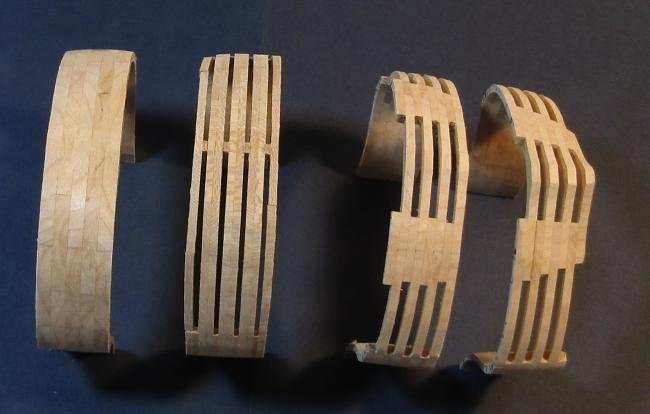
From left to right: 1 a station sandwich for a solid hull 2 all bends with the narrow space (St.P monograph) 3 Navall Timber framing 4 Navy Board I have to blink to see the difference between 3 & 4 but I am not objective about it. In the 18th century the RN shops used a different stylized framing. A single frame alternating with an equal space below the wale. It is a single timber in the region from the middle of the keel to enough above to keel to have a good bond. It is a really long piece of wood that circumscribes 90 degrees. I do not think I seen a photo of a model built using this method. I ones that I have seen are faux painting on a solid hull. Editorial (personal view): The 18th century stylized framing looks like a comb. The Hahn style (Davis) all bends with room = space looks like someone on a high sugar diet who never visits a dentist. I use #2 for hulls built from 1780 to 1860. The space width varies from ship to ship. In 1780 +/- the spaces tended to be only 1-2 inches. Not very pretty. #1 is quick and easy to do if I am going to completely plank the hull.
-
I have set for myself, rigid requirements for Navy Board framing: It should not be used for a model of any ship built after 1719. The first seriously enforced Establishments seems to be the 1719. Some here are disturbingly fast and loose about what is meant by Navy Board or even Admiralty. Navy Board is the late 17th century stylized framing method. Franklin wrote the definitive book exploring Navy Board and its variations. When it came out, the St. Philippe monograph blew my socks off. It is one of the few ships with reliable plans and is of the proper era. As an aside, I think that Navy Board framing was developed to provide three proof diagonals for a proposed design. Proof diagonals that were 3D and easily understood by the royals in charge but who were unschooled in the art. I did a series of station sandwich trials of various framing styles. It did it 1:120 for speed and material economy. The all bends with a narrow space between - no way would I entertain the insane table joints at the midline of a bend - back on point - is too timber wall like. The Navy Board framing revealed two serious penalties with this style. To get the solid belt at the turn of the bilge: The floor - which is a formidable and expensive timber with conventional framing - becomes unreasonably large. For there to be the solid belts, each end must turn up like the horns of a longhorn bull. It is much longer and has two reverse curves. The waste is almost as bad as with the Hahn method but the stock must be significantly wider than is used with Hahn. I can't justify it. Futtock 1 - although it is actually F1 and F3 - it goes from above the wale to well below the turn of the bilge. It is long - really long - and it defines an arc of near 90 degrees. It also needs wide stock and produces and lot of waste - close packing of patterns is difficult to do. I developed a compromise that has the solid belt and looks like Navy Board at first glace. The difference is that the spaces are all in the F1 frame. The floor is its normal 60% of beam length. F2 butts against the floor. It is longer than a normal F2, but it starts at the turn of the bilge so the arc is much less. I place a piece of timber that overlaps (scarphs) the floor to F2 joint that is the width of the solid belt of Navy Board. I named it Navall timber framing. The original navall timber was a free floating timber that started about halfway up the floor and overlapped the lower half of F2. It was between two floors but did not touch either one. Times passes and the navall timber evolves to be F1. In Navall timber framing as I have designed it, the timber is too long to be a chock but too short to be a futtock 1. Naming it a navall timber works for me even though it does bond to the floor on either side. I have framed a 1:60 hull of HMS Centurion 1732 using Navall Timber Framing. I have the bow framed also. I am well into the stern framing, but it is really a bear to do. But right now, my Muse has been gone for a while. It is another of my hulls in frame on the stocks. But it is a successful proof of concept as far as the method is concerned. There is one negative factor: the solid belt at the bilge and the solid wall above the wale is prone to humidity stress. Titebond II makes a strong bond, but in a few places, Mother Nature and expanding wood from internal water pressure has shown it self to be stronger than PVA. As for true miniature scale, there are several here, bur none are Navy Board. To me, a miniature is as much if not more about Art and artistry than straight forward ship modeling using wood. I think 1/8th scale 1:96 is more than enough crazy making. Going for an even smaller scale requires a special courage and inspiration. It does have the advantage of being economical as far as the cost of the wood.
-
How Did a Medieval Spice Cabinet Survive 500 Years Underwater?
Jaager replied to allanyed's topic in Nautical/Naval History
If I remember it correctly, the Baltic has a relatively low salinity, its depths have a very low oxygen concentration, it is dark, it is cold. Increased pressure lowers the freezing point of water, so the temp can be well below 0 degrees C. An environment where there is little to breakdown organic molecules. I suspect that re-exposure to normal atmosphere and temp will have the forces for natural recycling on afterburners. -
To enforce what Siggi answered and be emphatic in world of interest where there is very little to be emphatic about: Pins are not nails. They seldom tolerate being used as nails. Holes should always be drilled first. If you wish to remove them later, the hole diameter needs to be at least the same as the pin diameter. To save on frustration, the hole should be a done using a #drill bit that is a notch or two larger. I can think of no place, no job, with a ship model where a nail would be appropriate. Nowhere - where it would not be destructive. Most of the wood species that are scale appropriate have grain that is too tight and too dense to tolerate much compression. The force gets passed along as a split between the fibers. Superb work there Siggi!
-
Look up Dana Weger in the back issue CD's of the NRJ. I believe that hollowing out the layers is actually a requirement for acquisition by a USN museum. I view it as rather than "can" the situation during the planning stage is more "I need to have a really good reason not to hollow every layer but the bottom one." @Bob Cleek Champions at version of bread and butter that I had missed: Do the left and right sides as two pieces that meet at the midline. If I did not have an incurable case of POF disease, I think that I would have to do it this way. The pattern would be for one side. Bond the port side layer to (on top of) the stb side using something easily reversible - shellac, rubber cement, Duco, .... This is a two for one scroll cut process. Bandsaw the outer lines - outside and inside - then debond - add the mirror pattern to the port side piece and do the rough bevel. At the core plan to pattern stage I would add alignment sites for pins or Bamboo skewer dowels - so that port side pattern has something other than the outside shape to site it. These dowels can also be used to match layer 1 to layer 2, layer 2 to layer3, etc. in an idiot proof way. It is also probably good to have lines at and perpendicular to the midline at glue site. Using a jig for hole depth, dowels can be used to position port to stb and enforce the glue bond. 2nd question. Where would I get plans and/or cast parts for a WW1 warship? For reasons of sanity, I have limited myself to 1660-1860 wood and sail (obviously this is still too broad) so I can only speculate. Besides what I think is a lively steel group that hangs somewhere else - for USN I would look to the NA. For the RN, the NMM probably has more than you could ever want, For other European navies and Japan - you probably can find locals who would know. The AAMM has LE CHARLEMAGNE - first class battleship (1894-1920) Scale of drawing : 1/200th Le Hoche Battleship (1886 -1913) Taubman plans list at Loylhanna Dockyard looks like a possible source. A WWI warship's topsides are a lot busier and more interesting than the WWII generation, but the pre- Dreadnought / Great White Fleet steel vessels can be really interesting.
-
In addition to the above, when a hull gets into the 2-4 foot in length size, a solid block of wood gets into a weight problem range as well as the block possibly splitting as it ages. Bread and butter addresses those problems. But bread and butter is not a kit friendly method. @allanyedThe early Italian POB kits were really absurd in how few molds were used to support the first layer of planking. It is feasible and within easy reach to ameliorate deficiencies, it is wood after all, but investing in the additional skills and knowledge, no matter how slight, seems to be a step too far for many. @Chuck I think there are two distinctly different populations. Comparing POB to POF is like comparing Paint By Numbers to an original Rembrandt. To think that POB is a form of POF, no matter how good it makes someone doing POB feel, is self-deception. It is anything but that.
-
Yes indeed. It is not so much a disagreement as me using the wrong phrase. I think 'not invisible' is more appropriate than 'stands out'. There are many species of Bamboo, and some have darker end grain. Some cooperate with a draw plate peeling and some fight you all the way. The vision in my mind is of the photos of a contemporary model at NMM that has obvious and over scale hull planking trunnels. I have outwitted myself in where I filed my copies, so I can't name it, because I can't find them. I think it was the model of HMS Centurion that Siggi is using as a reference for his HMS Tiger. I have a feeling that something other than Bamboo was used in the 17th and 18th centuries in English ship model shops. Chinese food, woks, and fondue was probably not that big a thing back then. Your Inflexible is about as ideal as it gets. For the diameter to match scale, I am guessing 1:48? I picked 1:60 across the board, thinking that one half the size of museum scale would be something that I can live with. Going 1:120 would have been more practical, but I am not wired to build at miniature scale.
-
An especially obnoxious convention is two dark trunnels at each plank end and only the ends and the ends being placed at the same beam for every other strake. Using trunnels at all only makes sense if they are used as real mechanical fasteners. Then, the Bamboo end grain stands out even when that is unwanted. I think pulling enough Bamboo slivers for a deck or worse hull planking thru a #70 - #72 final size kills brain cells or at least gives them lactic acid poisoning.
-
Nick, From the perspective of someone looking at the impressive attrition rate for kits in the build logs just here, prudence would suggest a different ambition. From the way that you ask this question, I think this is another yacht situation. To be glib, if you have to ask, you are probably not ready to lose 5 or more years to HMS Victory 1765. You do not state that the ships that you have been building over 25 years are models built of wood. If they are plastic, except for any rigging, your experience may prove to be more of a hindrance than a help. The instructions are unlikely to measure up to the micro management style of plastic kit instructions. This lack of hand holding will offer you an excuse to bail when it gets frustrating. If you have prior experience with wood based kits, HMS Cruiser or HMS Snake look to be a way to immerse yourself in ships of the Nelson era without all of the endless repetition that a 1st rate involves. Building yet another model of HMS Victory 1765 will be the polar opposite of doing something even vaguely unique.
-
From an outsider and theoretical perspective: What is the need to fill the gaps between planking with anything for the first layer of a two layer POB hull? The entirety is covered by the second layer. If the problem is hollows between the molds - PVA glue a scab layer of wood veneer at the hollow. Pine or Basswood should be soft enough not to resist paring more than the actual first layer. For really shallow dips, a curl of Pine made using a plane should be a proper thickness.
-
PVA bonds are mechanical /physical bonds. While the words dry and cure are used for the bonding process, what is happening is the "poly" part. A catalyzed chemical reaction is occurring. The acrylamide units are bonding into long chains. These chains intrude into the irregular and porous surfaces of the two surfaces being bonded. It is a physical grip by PVA chains that makes the bond. Metals and plastics have smooth surfaces and have no pores. There is nothing for the PVA chains intrude into. For wood to wood, PVA is an excellent choice. For wood to metal or wood to plastic, you are wasting your effort. It ain't gonna bond. CA might work, but you are bonding a large surface area and the CA on a lot of it - the earliest applied - has probably finished its chemical reaction before the entire surface has been treated. It is just newly added bumps keeping the two surfaces from even touching. Epoxy is good for wood to metal. There are watery clear two part epoxy that have a long enough open time - if epoxy is compatible with polystyrene. There are a lot of kits with inadequate instructions, but for a kit that is using materials that are almost never used together, materials that probably should not be used together, materials that require a unique bonding agent, it is unconscionable not make suggestions for an agent suitable to bond them.
-
NAVY BOARD SHIP MODELS 1650-1750 FRANKLIN,JOHN US NAVAL INSTITUTE PRESS ANNAPOLIS, MD 1989 The primary focus is on ship models that are 100 years earlier than Bristol. But they are at the apex of ship modelers art. Probably not much direct help, but the models featured do show alternatives to an exact replication of every minor construction detail of a ship's innards.
-
These will be random and mostly unrelated thoughts: Bristol was at the end of the 18th century style warships. the older modelers conventions still have credibility. Starting about 1780 there was an inflection point in warship design. There was a long period (1780 - 1815 / 35 years) of near constant warfare with severe stress on both the treasury and resources. There were major improvements in artillery. Hull forms began their move from art to efficiency. The older conventions look out of place. My point? If you look at Franklin, you will see that many or most of those 17th century models used stylized construction - the ends did not mimic actual prototype timbering. Corners were cut. During the 18th century - the old Navy Board framing dropped - but for some if not most of the models, some form of stylized framing was used. It even extended to carved solid - either painted or full planked. Some were solid and painted with faux frames. The first fork is: for the hull below the wale... do you do a Bellona style exact engineering class demo model? or do you opt for a more artful model using one of several modelers conventions? The stern of Centurion - the vertical structural timbers between the windows had a different and increasing angle depending on their file. The windows had mullions that were different depending on how far out from the centerline they were. They were the same on every deck for the file they were in. Your transoms below the wing transom are not tenable. As a half hull they look OK - but as a P&S together whole, they describe too much of an arch. There was a fashion timber that was a cant. I do not care to futz with a cant frame, so I added a whole bend farther aft to fill where the fashion timber would be. I see the fashion frame as starting at the deadwood touching your farthest aft bend and angling to the outer end of the wing transom. My last bend is at the outer point of the wing transom. The inflection transom below the wing transom is at the level of the main gun deck beams. I made mine wider and carved a land for the deck planks - a wide landing.
-
This is a complicated and a "it depends" goal. If you want the popular version, use actual copper sheets or foil, to go deeply into decorator kitsch - use the material with soup bowl sized bumps. Neither will be realistic. A thin archival paper painted with a material containing metallic copper particles will be closer to scale. There are reactive follow on solutions to get as much or as little green or blue if and as desired. Being paper, PVA can be used to bond the plates. Coating the hull with PVA and letting dry at the start, coating the plates with PVA and letting it dry, allows for an iron with temp control to fix the plate to the hull -near instantly. An experiment to try: coat a sheet with PVA. paint the other side with copper. I am thinking that mineral spirits or terp based enamel (redundant?) would be better than water based paint - which probably does not like metallic copper anyway - as well as leaving a flat icky finish when dry. Then use the guillotine to get individual plates. This may not be kosher, but each sheet could be painted with a slightly different shade of copper - very slightly different -too show off the plates as being individuals. Questions: What is the effect of the paint on polymerized PVA on the other side of a sheet of paper? Would painting first and then coating with PVA on the other side produce a surface incompatible with PVA bonding to it? If it does not, that means that a wet coat of PVA on the other side of a painted plate could be used to bond the plate to a bare wood hull. With a 15 min open time, I am guessing that the wet to dry method could be complicated and slower to get a tight bond. I looked at your outside carved boat hull at this stage - and thought: 'what a wonderful mould!' Shellac the hull, Fix it upside down on a block. Mount the stem, keel, and stern. Saran Wrap or paraffin wax. Then use thick paper or thin cardboard as scale appropriate planking. It would be thin, so the rail need not be as wide. You could make as many replicates of the hull as you could possibly want. As well as not having to be perfect on your first try. For the ribs - use a wood that tolerates bending - dry heat bend - increment bend until it fits - being dry, PVA will be the bonding agent.
-
I am just speculating, but Old Brown and Franklin hide glues are convenient because they are used at room temp. The downside is that the water concentration has to be high enough to produce unwanted side effects in the wood being glued. If you are serious, you might oughta pay the price of the hassle of a glue pot. The water concentration is just enough to get a fluid - if you do it correctly. I break my rules this one time and use a man made synthetic -PVA - because a hot pot is too much extra work.
-
I have the old Dremel 1"/5" combo that is what preceded all of these others I have not really found a use for it. If you find you need a disc sander, one of the Byrens machines will serve you well. A belt sander seems to be aggressive. You are POB? I think you will really regret using one to bevel the moulds. It will eat more than you want it to, faster than you want it to. If you intend to use it to spill planks, there are much safer ways. A miniature hand plane can remove fine curls until you get to the sanding block stage. It has been a couple of lifetimes since I built a kit and none was POB. With that, I am having a difficult time visualizing a job for a belt sander with a POB build. Certainly no job that a hand tool would not do at a much lower cost and be easier to migrate with. I do use a 4"x36" el cheepo HF belt sander. It is excellent at doing bulk beveling of a 1"-2" thick plywood made of 12 layers of Hard Maple and Pine. But if you do that, you need to live alone. The cloud of saw dust makes Pigpen look pristine and a 1950's South Carolina cotton mill look like an operating room.
-
There is a fan that can be printed out in the Articles Database. The easy way is to use it with a tick strip. The TS gets you the open distance at each frame (for POF) at each mould (for POB). The fan gets you the sub division of that distance. There is no way to avoid distance creep during planking, so I advise measurement and subdivision after every plank is fixed to the hull. e.g marking off 8 (for example) segments at the beginning and expecting that last 8th plank width to match what was expected at the beginning is profound exercise in wishful thinking. Three goring belts is usually enough for most smaller hulls. I would start the measuring of the goring belts and their subdivisions after the wale and the garboard are fixed. The garboard is a special critter. It needs to be the size needed for it to do its job. If it is not correct, the rest does not matter.
-
As you survey the card commercial offerings, I am wondering if by using a program like GIMP, good mapping, and quality textures, you could scratch build just about any vessel with adequate plans?
-
Thru the lens of Time, A lathe and a mill are probably Yacht type acquisitions. i.e. for a yacht, if you have to ask, you can't afford it. For the two machines, the corollary is - especially if woodworking only, instead of or along with metal working: if you have to ask, you really do not need it yet.
-
Two lessons from this: It is not practical to scratch build unless you are or can access your own sawmill/millwork tools. Looks to be heading to you will have to be sawyer as well. It makes sense that in the UK, most old buildings are refurbished rather than removed and replaced.
-
I just checked Home Depot site. A 2x6 8' long is $8 that is actually 1.5" x 5.5" x ~2 m With a bandsaw and thickness sander you could get 2 layers for one side or 1 layer of the whole hull for ~ 16 L? If 1" layers - which is maybe too thick. You can probably get by with 6-8. A 2x6 x 10' ~3m = $10 or for you ~ 20 L. With 1/2" layers each board = 6 5.5" x 1 m Two boards may be enough. CYA = 3 boards that is ~60 L. If you beg nicely, you may find a local cabinetmaker or woodworker with a bandsaw. The lumberyard will maybe cross cut the board into 1 m lengths ( Measure your max hull length - add a buffer - longer than needed is wasteful, too short is a disaster.) The few cuts you need and using a softwood, the job is zip/zip. They may also have a big boy thickness sander.
-
Nu, unless you developed a magnetic attraction for the subject. I wrote that to make a point. The point is: with a wood ship model kit, all is never lost if you make a mistake. With wood, the same (or most often) better components can be self manufactured. The barrier to scratch is more imaginary than real, unlike with a kit of molded plastic pieces,

