Stockholm tar
-
Posts
866 -
Joined
-
Last visited
Content Type
Profiles
Forums
Gallery
Events
Everything posted by Stockholm tar
-
Spreaders are connected with the rigging, and 'spread' the topmast stays of many of the cutters in a thwartship direction. They had nothing to do with spreading the foot of the sails. Not all cutters were fitted with them. As far as I know the Sherbourne didn't have them, probably because she is early, but later vessels certainly did. I believe the spreaders were often fitted between the topmast and the lower mast head. The sheets of the topsail usually passed over sheaves in the lower yard below and thence to the deck. This yard is often referred to as the spread yard, since it spreads the foot of the topsail. It doesn't normally have a sail bent to it, although I think one could be set flying from it. As you imply, Frankie, it has braces and operates like a normal yard. Confusing perhaps, but the two things are quite different.
-
Rick, The opposite page also has two illustrations, that show the slot in the mastcap into which the the spreader fits. You have to bear in mind though the dates between the two cutters 1817, and about 1785, but there may not be that much difference.
-
Nils, It sounds as though it was ideal, nice location, caravanning and boating – what's not to like? It's a pity you had to give it up but, of course, understandable. Yes, I missed the sailing when I had to give it up, partly through ill health. The last time I was afloat was in 1998 (a week on the Norwegian ship Sörlandet) and I missed it for several years afterwards but then, as you say, there are model boats and, in our case, the cottage.
-
Hi Nils, Not so far, I'm afraid. However, as it's now 'next year', perhaps I should start thinking about it! Our thoughts are already on the cottage. We haven't been there for a couple of months so, as usual, we're wondering if everything is ok. There will be plenty of jobs that'll need doing when we move out there, but I'll make sure work on the SL won't suffer! (My wife's thoughts are largely about the garden – mine in that area usually concern the lawn mower!)
-
Nils, Thank you, much appreciated.
-
Jim, Thanks for the kind words.
-
Badger, Well, I can't see a lot wrong there, and I think with a bit more sanding it will look fine. Nice job around the gunports.
- 29 replies
-
- 1
-

-
- sherbourne
- caldercraft
- (and 1 more)
-
As a French ex POW said to his wife two hundred years ago, on his return to France from Britain in 1815 – in French of course!
-
Original Rigging for Cutters of 1763: with a Jib boom?
Stockholm tar replied to Gregor's topic in Masting, rigging and sails
Tony, I've just found out there's a Sherbourne (as in the ship's name) in Warwickshire, but it does sound a bit dubious. -
Original Rigging for Cutters of 1763: with a Jib boom?
Stockholm tar replied to Gregor's topic in Masting, rigging and sails
Tony, Not sure it's the Dorset town (where I've been a couple of times when I lived in Poole, many years ago). The town has no 'u' in the name, although I guess there may have been different ways of spelling it. One thought I had was to try to find out the names of any other cutters in her class, to see if there were pointers there. -
Original Rigging for Cutters of 1763: with a Jib boom?
Stockholm tar replied to Gregor's topic in Masting, rigging and sails
I'm still mystified about the jib boom too as, so far as I know, most just cutters had a straight bowsprit. I also have only have eight swivel guns as well. I left off two of the after ones because I thought it looked too crowded, and could imagine the crews getting in each other's way! Another mystery is the name, and have wondered where that might have come from. Some government or Admiralty official perhaps? -
Popeye, Thanks. She's coming on. Thanks also, guys, for the many 'likes'.
-
Badger, It's good that you've started a build log. You've done a fine job with the first planking. Give it a good sand, so that it's all smooth for the second layer of planks. Yes, I agree. Planking around the gunports is the best way to go. Those walnut planks too are rather brittle, so a good idea to replace them. I can't remember where in the instructions where it mentions drilling the holes for the forestay lanyard, but you might want to think about doing it soon before you add the bulwark capping rail, etc. Access will be a little difficult later on. (I imagine you'll want just three holes, since the large deadeye provided has that number. Other Sherbourne builders have drilled five, which would seem the more historically correct, but perhaps you're not that bothered.) At some stage you are asked to remove the frame tops with pliers. This sounded rather drastic to me, so I half cut through mine which made the removal easier. However, you seem to be passed that. If you have a dremel with a cutting attachment. that might be useful.
- 29 replies
-
- 1
-
-
- sherbourne
- caldercraft
- (and 1 more)
-
Thanks Eamonn. After that somewhat extensive, and obviously 'brilliant' explanation (which I think you'd agree didn't quite go to plan ) it's back to something simpler – sailmaking (hang on, did I just say simpler ? ) I was originally going to call it the 'January Sails' (do ya get it, january sales, january sails – eh? oh, never mind), but I got a bit behind, so March is now officially 'staysail month' . Apologies, btw, for the rather dark last photo. The weather's not too brilliant in these climes at this time of year. (Sun? Never heard of it...)
-
Hi Andreas, Only too glad to be of help. I can certainly understand you wanting to build the kit from the box, as this is your first, and that's fine. Of course the choice of stand is up to you, and I actually used the kit stand too (after thinking of other options) although I cut down the sides a bit, as to my mind they obscured the hull too much. Re. the 'basic' plans. I think kit plans of many manufacturers are fairly simple, which often leads the modeller up in the air (and that's where MSW comes in of course). Having said that, I believe some kit instructions are quite good – although I can't really comment on them, since they haven't come my way! Sherbourne is only my second model. The first was Billings, Bluenose ll, and their instructions certainly were nothing to write home about! Reading between the lines of a plan comes with experience and reading on the subject, I guess. Tony makes a good point about making one of the guns up, to test fit it through the ports when the time comes. However, here the main thing is to glue the gunport strips as exactly level as you can. The one on the port side of my model is slightly down at the after end. I thought it wouldn't matter too much, but boy was I wrong, and I had no end of trouble in getting the two aftermost guns to fit through the ports. I had to resort to such things as: slightly flattening the wheels where they touch the deck, lowering the barrel by deepening the slots where it fits on the carriage, filing the upper edge of the gun ports themselves, etc. Even now, they barely get through the ports! This could all have been avoided, had I made sure the strips were on right in the first place, so when you get to that point take your time to do it properly. One other point. If you're interested, it might be a good idea to start a small collection of modelling books, to learn the basic terms and techniques. (There's also quite a bit on this site about that.) One that I and others have found useful in respect of Sherbourne, is 'The Naval Cutter Alert 1777' by Peter Goodwin, in the Anatomy of the Ship series. It's not the definitive guide, and not about Sherbourne, but Alert is only a few years later date wise. There is also quite a lot of background information on cutters. It has been a great help.
- 23 replies
-
- 1
-
-
- sherbourne
- caldercraft
- (and 1 more)
-
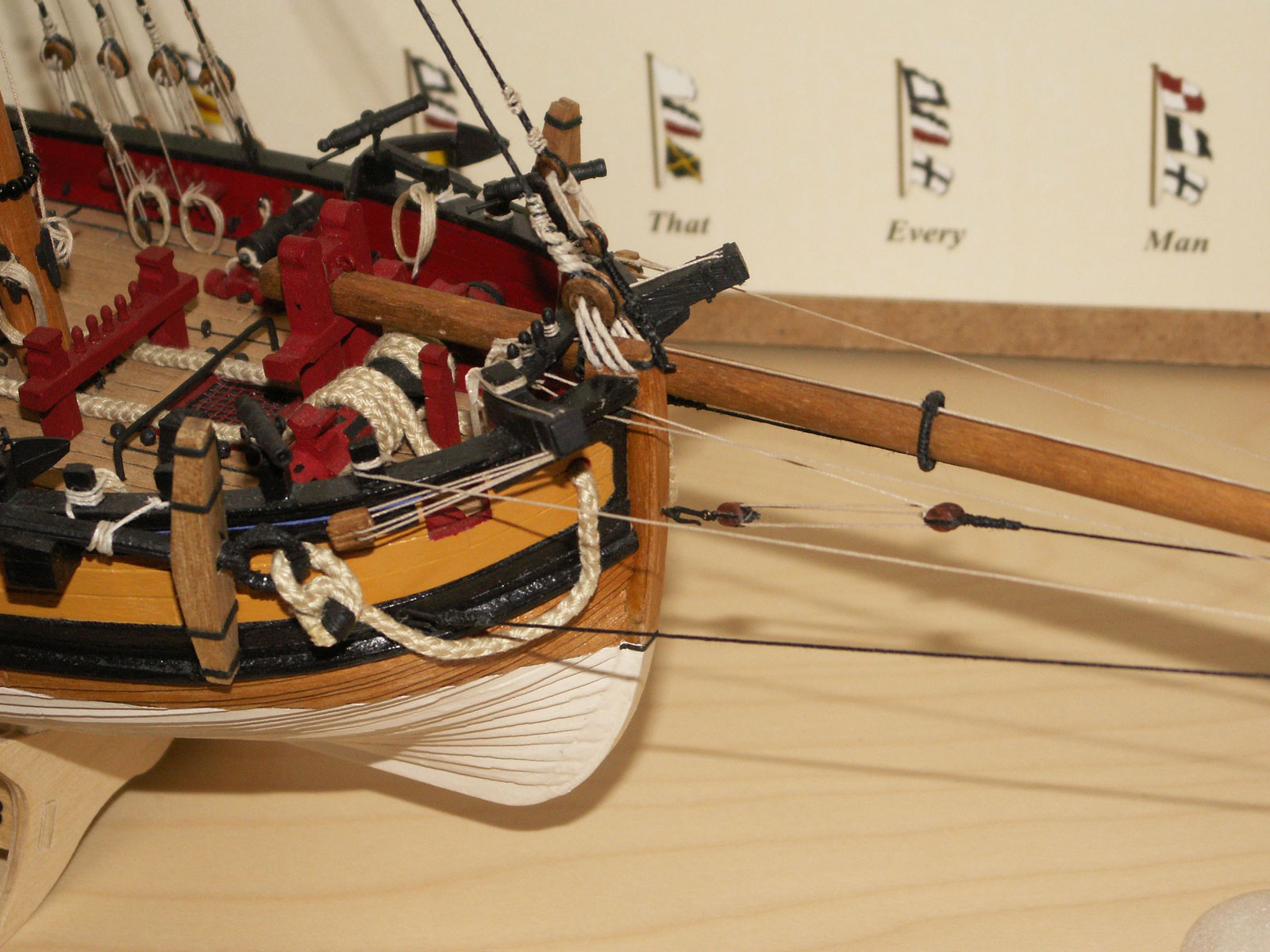
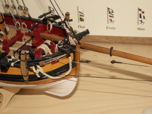
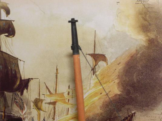
The topgallant stay is most likely the longest single piece of standing rigging on the cutter, at approximately 75cm in length. It runs from the topgallant masthead, through a block on the top of the cranse iron at the end of the bowsprit, and is then seized to the upper double block of a tackle hooked to the stem. Consulting the drawings in the AOTS Alert book however, produced another discrepancy. The illustration on page 104 shows the stay as running through a single block fitted to an eyebolt on the top of the cranse iron, yet that on page 115 (an end on view of the bowsprit) shows it as passing through the central sheave of a triple block – the two outer sheaves being used for the topsail yard braces. So, which is correct? After a little thought I decided to use the triple block arrangement, as not only would it seem to be the more common, but it also reduces the number of blocks at the end of bowsprit – where it is already getting a little crowded. If I had used a single block for the stay the braces would still have to be accommodated, most likely by using two single blocks, and I still have to fit two single blocks for the topsail bowlines, on strops just inboard of the cranse iron. The triple block itself, of course, is not supplied with the kit and I bought a suitably stained and polished 5mm pear example – or rather, examples, as it came with nine others. I decided to fit the eyebolt on the stem first, to take the lower double block of the stay tackle. On stropping the block, and at the same time fitting on to it one of the hooks supplied with the kit, I first tried using thin brass wire. This had, of course, first to be painted black but the process turned out to be less than satisfactory, as the paint didn’t take on the metal too well. Even after two coats the wire showed through in a few places and flaked off when bent and the wire itself, although thin, also didn’t form itself satisfactorily around the block. Instead I substituted black rigging cord, which not only doesn’t need painting (with the ever present risk of getting black paint on the nicely varnished block) but formed naturally around the block when tightened. I fastened it with a small flat (reef) knot and a spot of glue secured it in place. The triple block on the cranse iron was stropped in the same way, except that here an eyebolt was used in place of the hook, which fitted into a hole drilled through the iron into the bowsprit. Again the reef knot didn’t look overscale: Incidentally, the stained and polished blocks I am using for the rigging (triples, doubles and singles) whilst looking good, unfortunately only have a token mark where the groove for the strop should be, the actual groove having to be carefully filed out. This is a somewhat tricky operation initially, to ensure that the groove is made in the centre of the block, but once this has been carefully started (I normally hold the block in one hand, using self closing tweezers, and a suitably-sized file in the other) a few more gentle passes with the file produces a nice clean slot. The smaller the block, of course, the more difficult it is to file – and I just can’t wait to get to those 3mm single blocks! Having cut the right length for the topgallant stay, using 0.25 black thread, the next task was to turn in, and seize, the double block at its lower end. Having done this on the serving machine, I waxed the line and then passed the other end through the central sheave of the block on the cranse iron. I formed a slip knot at that end, which was passed over the topgallant masthead and seated down on the mast stops. It was a little tricky, when working the knot tight, to get the double block at the other end of the stay in the right position to satisfactorily correspond with the one attached to the stem. However I think I managed it about right: A problem, which I had actually been concerning about for some while, now presented itself. This concerned the route taken by the various lines, from the end of bowsprit to their pins on the forward pinrail and whether they should pass over, or go through, the forward bulwark. I believe this was commented on by Gregor in his log. The jib traveller outhaul I had rigged some time before, and as it is shown in the Alert book. The drawing shows it passing down through the bowsprit sheave, running back along under the sprit and then up through a single block fixed to an eyebolt on the wale, next to the stem. From there it passes up and over the rail and thence to its pin. Even though this might be correct, I have to agree that this arrangement does create a somewhat sharp bend in the line, where it passes over the rail and which, on the real vessel, would most certainly be a point of chafe. I therefore decided, as did Gregor, to drill some small holes directly through the bulwark so that both the traveller outhaul, and the topgallant stay tackle, follow what I think is a more seamanlike route to their respective pins (see picture 1). It also looks a lot neater. The problem when doing the above, was not only to get the holes drilled in the correct places, but also to avoid getting the drill snarled up in the bowsprit shrouds – which had already been rigged – so I had to be somewhat careful. However, I managed it without too much hassle and, more importantly, without causing any damage! Next time: the staysail.
-
Andreas, Yes, it is as Tony says. Trim the bottom of the bulkheads so they're flush with the base of the keel. It's important that the upper edge and the top of the keel are level too, to get the right curvature for the deck. Like him, I also glued the keel piece, stem and stern posts, before I did the planking, but perhaps adding them afterwards might have been better. Re. his other two points: 1) Drilling five holes in the top of the stem piece would seem to be the more historically accurate, rather than the three as shown in the kit. I probably would have done it, had I thought about it early enough – and at about the point you are now – but as it is, I just beefed up the size of the lanyard! You'd also have to think about the position of the holes – whether its three above and two below, or the other way around. Of course, you'd also have to replace the deadeye from the kit with a five-hole one. Unfortunately, kit firms don't seem to make them (it looks like Caldercraft just provided a bigger three-hole one, similar to those for the deadeyes) so you would probably have to make your own. 2) Entirely up to you of course, whether you use the kit stand or go for something better, but if the latter now is the time to do it. I'll add another two points, which I think might make things easier later on: 3) Cut about half of the way through all the frame tops at deck level. Yes, you read that right – but don't get alarmed! As far as I remember from the instructions, it says something like 'with a pair of pliers, twist off the frame tops,' which you have to remove, to fit the inner bulwark planking. I thought that there was no way I was going to do that, without causing serious damage, so hit on this simple solution. With the pliers I then only had to break off the remaining wood that was left, which wasn't a problem, and it didn't leave an unsightly mess of broken wood. It's then just a question of tidying up with sandpaper. It's probably best to make the cut from the side, and cutting half-way through leaves enough for some rigidity. Also, don't use too much glue, where the frame tops touch the gunport strips. 4) Always read ahead of where you are in the build, and try to spot any potential problems before you get to them, which you might be able to avoid – advice I don't always take myself!
- 23 replies
-
- 2
-
-
- sherbourne
- caldercraft
- (and 1 more)
-
John, Ok, do that, then we can see exactly what you mean. I'm guessing though, you've only planked the outside of the gunport strip so far, which means the gunport openings will still be visible from the inside. With care and a sharp knife (and the model on its side) you might be able to roughly cut them out from the inside and tidy them up with sandpaper and a file afterwards.
-
John, I don't understand exactly what you mean by 'drilling' the gun ports. When planking the gunport strips, you should have planked around the ports, both inside and out. Does this mean you have planked over them with your first planking? Don't worry too much, as I am sure it can be sorted it out. Yes, the walnut planking is a bit of a pain and it splits and flakes quite easily. The thing is to go careful with it. Also, don't be embarrassed about starting a build log, as you'll find this is the best way that members can offer advice. If you have a digital camera, adding pictures is a great help.
-
Andreas, Bow and stern blocks provide a greater area for gluing the planks in both these areas where the bend is considerable, especially at the bow. However I think the use of them also depends on the particular model and the spacing of the bulkheads. On Sherbourne, I found that the bulkheads were fairly close together and the curvature not that severe, therefore I didn't feel they were particularly necessary. Their use, however, is really up to you. I bent the planks in the bow area with a pair of plank nippers, which score the underside of the plank. These do have to be used with care however, and I know some model makers don't like them, preferring to use other methods. I have never used nails, but special pins with a shoulder are useful to initially hold the plank whilst the glue dries, removing them afterwards. A tip here is to not pin directly through a plank, which tends to split it, but to drill a small hole for it into the frames just outside where the edge of the plank will lie. The shoulder will firmly hold the plank down until the glue sets. I'm not sure about blocks between the frames, and have never used them. A beauty about the Sherbourne is that she is double planked, so it doesn't particularly matter if the first planking isn't that good – although I am sure yours will be!
- 23 replies
-
- 3
-
-
- sherbourne
- caldercraft
- (and 1 more)
-
Andreas, I think you'll find the 'simple hull-planking techniques for beginners' guide here, and the directions on most kit plans, certainly these ones, are two different animals! Kit plans are usually pretty minimal, or non existent, so you would have to mark out the bearding line and the rabbet yourself – that is if you wish to. Honestly, I don't actually think they're actually necessary, although they may make the planking easier. I didn't do either with my Sherbourne, although I remember I did taper the garboard plank edge where it fitted the keel. You'll appreciate that's some time ago now!
- 23 replies
-
- 1
-
-
- sherbourne
- caldercraft
- (and 1 more)
-
Rigging a bowsprit heel rope on Cutter Sherbourne 1763
Stockholm tar replied to tkay11's topic in Masting, rigging and sails
Tony, Yes, temporarily fitting blocks and tackles to the mast would certainly give a mechanical advantage. -
Rigging a bowsprit heel rope on Cutter Sherbourne 1763
Stockholm tar replied to tkay11's topic in Masting, rigging and sails
Tony, I agree largely with what you say in your previous post. Re. the moving of the bowsprit inboard, and the seeming impossibility of the windlass being used due to its position, I wonder if the solution was actually not rather more simple. What if two ropes were fastened to the butt end of the spar, one on each side (using eyebolts or some other suitable means), and these were then simply hauled upon by members of the crew, stretched aft along their length? These cutters had a crew of around 40 men, so manpower wouldn't have been a problem and I can't see it as being that difficult. Running it out again, the windlass could obviously be employed. Spyglass, I would say that the bowsprit's being run-in, in harbour, was rather a different proposition to what we are talking about here. I have never been on a vessel where the bowsprit has been moved, but from what I've read on the subject and historical pictures of vessels with run-in spars, they have always been taken in completely. Given that, I can't then see the reason for the three fid holes, other than to adjust its length when in use.- 14 replies
-
- 1
-
-
- Heel rope
- Sherbourne
- (and 1 more)
-
Eamonn, There's some blushing going on over here, as well! :blush:
- 1,039 replies
-
- 1
-
-
- ballahoo
- caldercraft
- (and 2 more)
-
Rigging a bowsprit heel rope on Cutter Sherbourne 1763
Stockholm tar replied to tkay11's topic in Masting, rigging and sails
Tony, Interesting discussion. On my Sherbourne there is about 3.5cm between the butt end of the bowsprit and the mast, which doesn't seem to make a lot of fore and aft movement possible. However, on the real vessel fine tuning might be the order of the day, so it could be worthwhile. I squared the butt end of my bowsprit, and also gave it three fid holes (although not a sheave hole) – although I have to admit these were for appearance, rather than for any practical use in reality! Since the spar on the actual cutters was pretty hefty, I wouldn't have thought that two or three reasonably-sized fid holes would have weakened it over much – and it is supported either side of the hole. Do you intend rigging the blocks etc, or just have the fittings? I wouldn't have thought they were permanently rigged. In passing, it seems difficult to find information on this.