MORE HANDBOOKS ARE ON THEIR WAY! We will let you know when they get here.
×


Stockholm tar
-
Posts
866 -
Joined
-
Last visited
Content Type
Profiles
Forums
Gallery
Events
Everything posted by Stockholm tar
-
Menno, It is sometimes called a propellor 'aperture' in English.
-
Mk, Yes, I think you could do that. Hang them from the 'horns', as it were, and it will look ok. I would imagine the kit instructions tell you to hang them on the outside for effect. I doubt they would have done this in reality though, since it may have been necessary to get to them in a hurry – and there is always the added possibility they could come adrift. One other general point. I noticed that your blocks look a little too square. Not really a criticism, but they should be rounded off rather more. Something to bear in mind for your next model, when you might even consider buying some better ones? Btw, glad my method of making coils worked for you.
-
Mk, (Mike?) 1. Coils are normally of a size that they hang from the level of the rail, to just a few inches short of the deck. This is largely so that they won't pick up any water from the deck (which will cause rot). 2. In short, no, they would either get washed, or knocked, over the side in no time - and probably end up in a tangle. Belaying pins are of some antiquity, and I certainly think a vessel of your vintage (1400's?) would have had them, so the kit is probably accurate there. I am surprised though that they show the coils outside the bulwarks, when they should be inside. There looks to be enough room to me, to fit them. 3. The other pic you posted shows the 'top', as it is called, at the doubling of the lower mast and top mast. Again any coils hung over the side without an anchorage point, would soon disappear below! So the few lies belayed there would either have a pin or perhaps they may be made fast to a cleat.
-
Where is a good place to buy from? - moved by moderator
Stockholm tar replied to wdretired's topic in Wood ship model kits
I would second Mike's suggestion, Cornwall Model Boats. Their prices seem to be cheaper than elsewhere, and they provide a good service: http://www.cornwallmodelboats.co.uk/index.html -
Geoff, That's just my opinion, of course.
-
Allan, I think this contemporary model may have natural standing rigging for very simple reasons. These 'dockyard' models were basically built to show the design of a ship, and the colour of the rigging was the least of their concerns. Everyone knew what tarred rigging looked like, so why go to the expense of reproducing it? The model maker may perhaps also not have had any black thread to hand, and would have had to go to the lengthy process of dying some. That again would have been uneccessary. Today, I think we tend to look at these models from an aesthetic point of view, rather than the practical one which they did. Don't forget a war was probably in the offing, was being fought, or was perhaps just over before the next one, so they were somewhat differently motivated. They wanted to get the ship built as soon as possible! Andy, It became the the seamen's 'problem' once the first lieutenant learnt of the tar on his spotless deck! Frankie, Hence the naval salute today is palm down, the other services palm facing outwards. The tar of course would have been on the seamen's hands, since you are taught to grasp the shrouds when climbing not the ratlines – they can part without warning. For the record, from my own experience, I have never come across tarred ratlines.
-
Mark, Nice job, and it didn't turn out so bad in the end. Sometimes, I think our fears often get in the way of attempting the obvious. Btw, I trust that what it says on the mug, wasn't in the mug at the time?
-
Eamonn, Mention of the tiller rminds me that I made a new one for Sherbourne. The kit tiller was not long enough, and at the rudder-head end had a an almost circular bit that went around the head itself. A very strange arrangement. The new one is scale ten feet, as specified for the Alert in the AOTS book, and has a tenon which fits through the top of the rudder head. I also added a couple of paper 'bands' to look like iron ones. I don't know what your tiller looks like, but if it is anything like the one I had, I'd certainly make a new one. If it's any consolation, I used the kit guns too – although I admit they could have been better!
- 1,039 replies
-
- 1
-

-
- ballahoo
- caldercraft
- (and 2 more)
-
Eamonn, I'm sure your perseverance will win through – after all everything's hinging on it! As to the rudder head and tiller, I should paint them whatever colours you think looks best. I don't think there were any particular rules about it. I left the rudder head on Sherbourne natural, and painted the tiller white, which I think looked good. Entirely up to you though!
- 1,039 replies
-
- 4
-
-
- ballahoo
- caldercraft
- (and 2 more)
-
Try using two pins per gun.
-
Rich, I would say yes, and also pin them. The latter can be achieved, by a strategically placed pin under the centre of each axle, such that it is not visible from the outside. A light smear of glue on the trucks can also help. It is probably advisable to fix the guns down to prevent subsequent any movement, particularly under a deck where they can't later be reached.
-
Mk, Have a look at my Sherbourne log, the link to it is in my signature. Specifically the best views of coils are on page 3, post No. 40; page 5, post 68; page 8, post 113; page 9, post 132; and page 10, post 143.
-
Mkmossop, As Mike implied most, if not all, lines will have a working length, which means the end will be coiled to a belaying pin (normally clockwise). The coils will also roughly be about the same size (although each may not have the same amount of line) and hang just clear of the deck, to prevent them picking up any wet or damp from it. The way I make mine is to cut off a length of thread appropriate for that particular line you have in mind. You can more-or-less gauge this by thinking of the job it does on the ship, and the distance it may have to 'run', eg. for the braces, how far are the yards are likely to swing, fore and aft? This may not seem important, but will most likely be spotted by anyone who knows. (Btw, in the same way, if you were to have the yards on your model braced round, the side which has the yardarms furthest aft, would have more line on that side than the other. Similarly with halliards. If the yards, or staysails, are hoisted then there would be more rope to the coils, than if they were lowered.) A useful way to make coils, I have found, is to use a pair of closed tapered pliers (you can keep them closed with an elastic band around the handles). Then, having gauged how large you wish to make the coil (the taper of the pliers helps here), take the amount of line you need and run it through your thumb and forefinger, which are lightly smeared with glue (I use wood glue). Beginning with one end, at an appropriate point on the pliers, slowly wrap the line around the plier nose (in a clockwise direction) so that the turns are close to one another, for the length of the line. Some care is needed to ensure the turns are even, but it doesn't matter that they overlap here and there, as it will look more realistic. The end should come down the right side of the coil, and I normally cut it off about half way down. You should now have a coil glued to itself, but not of course the pliers! Before it is quite dry slip the coil off the nose, and press into more of an oval shape. Then when dry you will have a nice looking coil ready to glue to the rail at the pin. Any dry glue that adheres itself to the pliers can be quickly removed with a fine sandpaper. I hope this helps.
-
Klaus, Many thanks. The cross-section shows them to a certain extent. I have been looking for close up photos of her in dry dock, but those I have found are overall views of the ship – not too helpful as regards disposition of the strakes! If you find anything amongst what sounds like an extensive collection of photographs, I'd certainly be interested. Thanks also for the offer of photos of details. You can bet I'll let you know, if there's something I need help with! However, as this is still all some way off, there's time for investigation. The plan pack might be interesting to buy in any case for additional information, if they are their own plans. I already have the two pertinent ones by Underhill.
-
Nils, Ok, thanks. I will have a look at the Heinrich Kayser's log.
-
Nils, Thank you for the diagram and explanation of the plating procedure. That will come in very useful nearer the time – and when I've worked out how many actual strakes there are. I also have it in mind to contact the SL Foundation, for any extra information they have. I've just been looking at your Pamir log, I think page five, where you use the aluminium foil. I must say it does look impressive, but wondered how you managed to get the paint to take on it? I'm presuming it has a shiny surface. Anyway, thanks again.
-
Hello Nigel, Well, I do hope so, and thanks for the compliment. As you say this will be an extra special one, and it will be interesting to see how she turns out. Pull up a chair by all means.
-
Nils, Thank you very much, for that information. I somehow thought you would know! There's a lot to think about there and, as you suggest, we can talk about that the nearer I get to that point. Thanks for the info on the adhesive foil; it seems as though that might be the way to go, but again we can discuss this later. Interesting regarding the Pamir capsize and subsequent enquiry, and the fact that the hull appeared to have opened at precisely the point of the newer welding. I'm not suggesting, of course, this has been done on the SL's hull, but it is certainly strange that the rivet heads are not more noticeable. Thanks once again,
-
Hi Nils, Thank you, and I'm glad you liked the introduction. As you say I think, and hope, she will at least turn out to be a fair appoximation of the original. I'm as interested as anyone to see how she turns out and I will, of course, post updates with pictures whenever possible. Actually, I'm glad you looked in as one things I have been thinking of – and which I'm sure you would know about – is how to replicate the steel hull plating. Obviously, this will have to be done in wood! The plating runs in bands which can be seen in some photographs of her, particularly from the bow and stern, and in certain conditions of light. My idea is to double plank the hull, with the second being of slightly varying thicknesses, indicating the run of the bands. I wonder what you think of this idea? One other small point. In 1914 SL (or rather GFA) obviously had a rivetted hull but, on close examination of various photographs, the heads would not seem to be very evident today – apart from the stem, around the bow, and perhaps a little at the stern. This leads me to think they've either flattened the heads and done a very good paint job, or she's been welded during her various refits. I would, however, think the latter rather difficult to do! Perhaps though, I'm overthinking the idea.
-
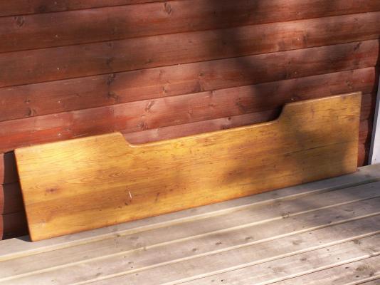
Hi Eamonn, Thanks for looking in. You might almost say the bench (and I think it is that), soon to be a backboard, was almost tailor-made for the job. It seems to be just the right size. As to the text, I haven't really quite thought that far ahead, but I am incline to use some form of lettering – my carving skills being what they are, ie. non existent! I hadn't actually thought of a brass plate. With lettering you can, of course, 'spread it out across the board' (ha-ha), bearing in mind that part of the surface will necessarily be obscured by the model. I'll have to work out how much of the area I can reasonably use for it, but it's obviously going to be the top half of the board. I can also visualise the finished article easily enough in my mind's eye – it's the getting there that's probably going to be a bit tricky!
-
mary rose partwork by hachette - moved by moderator
Stockholm tar replied to geoff's topic in Wood ship model kits
I think I'd agree with the other comments, the Caldercraft kit is the one to go for. Even though it was produced a little while ago now, it is certainly a lot cheaper, when you work it out (currently I think around £240 from Cornwall Model boats) and is probably better quality. It was also made with the help of the Mary Rose Trust. You also mention you had delivery issues with the Black Pearl; so what's to say you won't have the same problems again? I think these partworks are a bit of a con. Their kits look inviting, which of course is the intention but, once you take the plunge, it's probably difficult to get out of the situation should you wish to. Have you also noticed that the total price is very hard to find? -
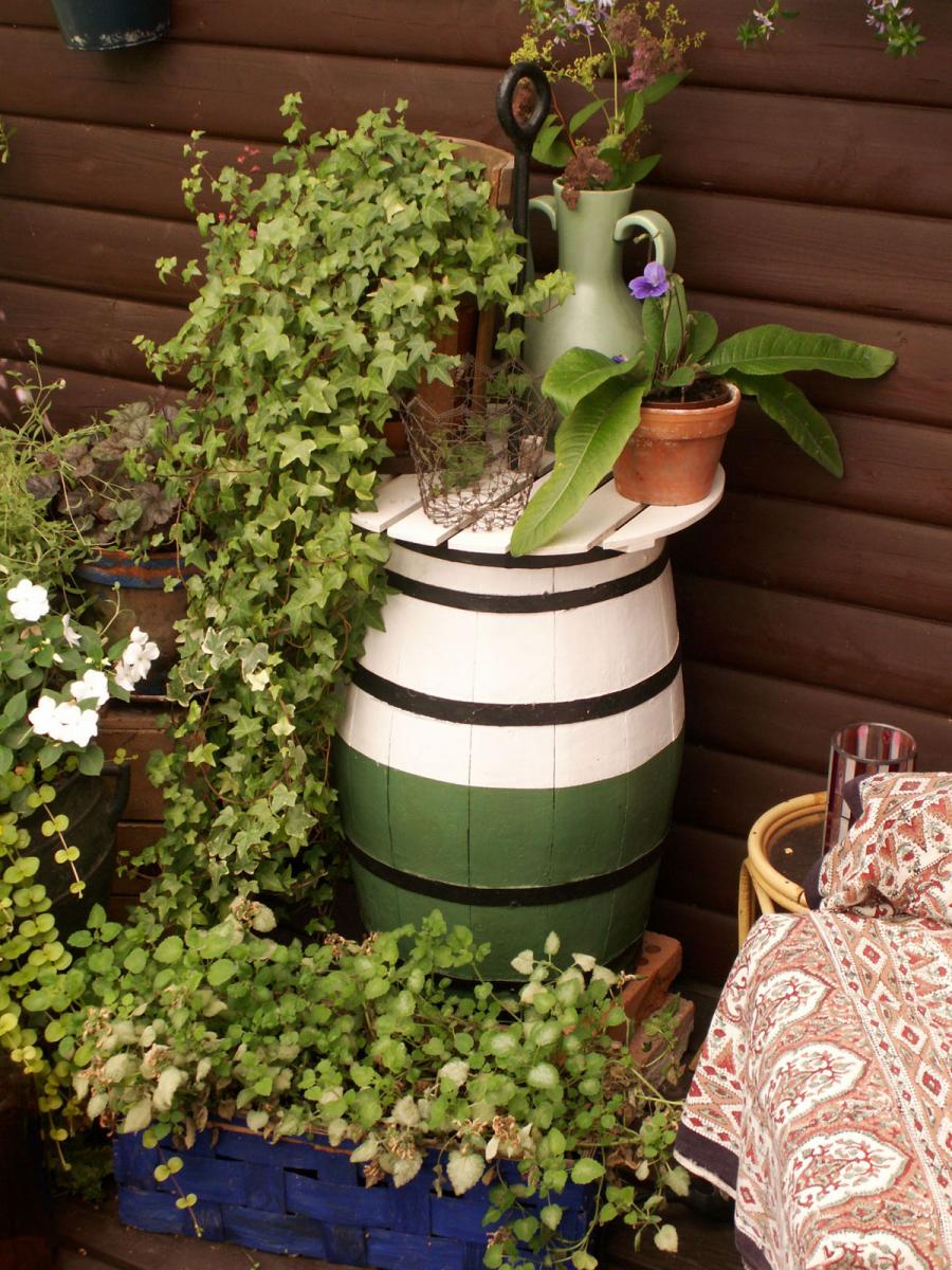
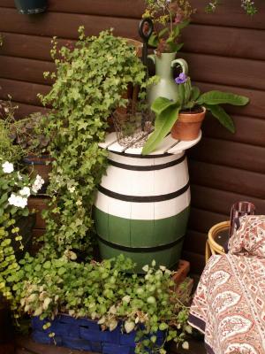
I am somewhat surprised that there don’t seem to be many models of the SL in existence, given that she is such a beautiful vessel. I imagine this is because she is not so well known to the general public, or famous – and has no guns – thus kit firms are not interested in modelling her, or indeed, many another interesting ship. However, there is a superb, scratch-built, scale model of her in Bergen Maritime Museum (itself well worth a visit if you get the opportunity) that I visited following my initial cruise, and before the subsequent passage to Leith: https://www.google.se/search?q=bergen+maritime+museum&client=firefox-a&hs=B7G&rls=org.mozilla:sv-SE:official&channel=sb&tbm=isch&tbo=u&source=univ&sa=X&ei=Ai_NU4zAMOuGywOb0oGoAw&ved=0CFoQsAQ&biw=1045&bih=503#facrc=_&imgdii=_&imgrc=ajXj6tPFHydEPM%253A%3BY2peWq2Sy7VaFM%3Bhttp%253A%252F%252Ffarm9.staticflickr.com%252F8251%252F8642773423_4606ecf87a.jpg%3Bhttp%253A%252F%252Fwww.flickr.com%252Fphotos%252Feugenephoen%252F8642773423%252F%3B681%3B1024 Returning to my half model Underhill, in his drawings for the Grossherzog Friedrich August, gave her 33 frames and I will replicate these – although, of course, they will be half frames. As mentioned I intend to make them of birch ply, fixed to a backboard. The search for the latter, incidentally, turned out to be something of a saga on its own, which might be interesting to relate here. Whilst rummaging through the clutter in the cottage attic for something that I perhaps might be able to use, I turned up several boards that looked to be of approximately the right size and took them down for further examination. The first one I lifted out had originally come from my father-in-law’s old yacht, which he had kept perhaps as a souvenir – and of which my wife and I have now been the proud owners for several years. There were other boards of roughly similar size and dimensions but, under closer scrutiny, they turned out to be either too thin, too thick, too short, or made from chipboard – the latter of which, I think you will agree, would not do anything to enhance the finished model! So they all went back from whence they came, and I was left with the aforementioned item of yacht ‘furniture’. This set me to thinking: ‘I might be able to use that, if it turns out to be the right size, and it somehow seems appropriate. After all, it came from a yacht that had been an enjoyable part of my father-in-law’s life; it will become a backboard for the half-hull of a vessel being made for his daughter, on board of which we first met; and last, but perhaps not least, I can think of no other use for it.’ Taking a tape measure, the board turned out to be 130.5 cm in length at the top, its widest point, (it tapers slightly to 127.5 cm at the bottom), is 32 cm deep, and is 1.5 cm in thickness. It also has five strengthening pieces spaced on the reverse. So it seems ideal for the half-model, the sparred length of which measures approx 102 cm including the bowsprit. It will also give the backboard itself a new lease of life, as for all the years we’ve had it, we’ve never known quite what to do with it – but, of course, just knew it would come in useful one day! Well, that day has now arrived, and my wife thought it a great idea – so it has also received her blessing: Although not certain, I believe it is the yacht’s cockpit bench. We have a few old photos of the yacht at home, and I’ll try and find one that shows it. The yacht by the way was of a type called a Skärgårds (archipelago) cruiser which was, and still is, a popular type in Swedish waters. Although I believe they have changed to a certain extent over the years, dependant on the class rules, many of the older boats are still in use having been lovingly restored. My ex. Swedish navy father-in-law bought her second hand and she probably dates from the fifties. He named her ‘Spray’, sailing extensively her until the mid seventies when she was sold. This was some years of course before I knew him, so I never saw the yacht, which I always thought that was a pity as I’m sure it would have been fun to sail with him. We also have Spray’s mooring buoy, which I have restored and turned into a nifty coffee table – although at the moment it is doing stalwart duty as part of my wife’s annual summer floral display on the veranda, where it is supporting a few plant pots! The bench is in quite good condition, and really just needs a light sanding and re-varnishing. I thought to put some suitable wording on the backboard, such as the barque’s name, length, tonnage etc., and at the moment I am in two minds as to whether to varnish it before adding the lettering, or after. I am inclined to the latter. The bench (and attached model) will, of course, need some support brackets, for it to stand on the bookcase. As I mentioned it is, as you would expect, reasonably heavy so they will have to be somewhat substantial. I was thinking along the lines of a couple of dolphins, but I’ll have to think a little more about that. Anyway to finish off, and for the sake of completeness, here's the mooring buoy: The next instalment will, hopefully, see the commencement of the build.
-
Sal, I believe Kurt is correct. From what I can see in the photograph, this would actually appear to be the 'stock' for this type of anchor, ie. a smaller or kedge type. The stock is also iron, and roughly as long as the anchor is. It passes through the top of the anchor 'shank', being held by a swelling at the end, and is thus hinged, so that it can be closed along the anchor shank for stowage. When in use, the stock is pushed up through the head of the anchor, until it comes up against a swelling in the middle of it, and is then normally fixed in place by a pin or forelock. The stock is then at its mid point on the anchor, with the arms on each side being equidistant. The stock is set at right angles to the 'flukes' (the bits that dig in) and it's job is to turn the anchor over on the sea bed, so that this will happen. Larger ships had fixed stocks, which for those of Victory's period were wooden.
-
Eamonn, I think black paper of a suitable thickness, would work. As Jason pointed out, metal would probably look overscale.
- 1,039 replies
-
- 2
-
-
- ballahoo
- caldercraft
- (and 2 more)
-
Nils, You're making a really good job on your Pegasus; I love all the little details and the hammocks look just the job. Btw I believe Peter Goodwin, ex curator of the Victory, was one of the consultants for the film.