MORE HANDBOOKS ARE ON THEIR WAY! We will let you know when they get here.
×


Stockholm tar
-
Posts
866 -
Joined
-
Last visited
Content Type
Profiles
Forums
Gallery
Events
Everything posted by Stockholm tar
-
Nils, Yes, that should work. It means, of course, that the thole pins or rowlocks will have to be moved forward on the starboard side.
-
Nils, I like your boat, it looks great. However, you might want to think about the diposition of the crew. You have drawn them 'single' banked (one per thwart or seat), rather than 'double' banked (two per thwart), which is fine for the captain's gig – but I doubt they would have sat in the centre of the thwart. I remember from my sea scout days, where we had a large pulling and sailing gig, that the crew sat on alternate sides, the oars (about 12' long) being over the opposite side of the thwart. Thus the bow oar, no. 3 and no. 5 (or 'stroke', the one nearest the coxswain or helmsman, and from whom the others take their timing) sit on the port side and their oars are out to starboard. Nos. 2 and 4 sat on the starboard side, with their oars out to port. I seem to remember we only used five oarsmen, rather than six, which would mean keeping this system might be problematic! Normally the bow oar was stowed with the blade facing forward and it was also a little shorter, due to the curve of the bow. I think it was also stowed down the centre of the boat, for ease in getting it out. Incidentally, I had a look in my (1972) Admiralty ManuaI of Seamanship and they have the same disposition for an RN montague whaler, which your drawing somewhat resembles, although the after mast is rather smaller. I hope this helps, rather than confuses!
-
Gregor, She's looking great. I know what you mean about the bight of the stay around the mast. I believe I mentioned in my last log posting, that I thought I had made mine a little too small – not by much, but giving just about enough room for the halliard to pass through it and belay to the rail in front of the mast, without fouling too much on the way. The preventer stay, which I am now in the process of fitting, makes it even more confined. I don't think the yard will be a problem in this regard, as it is set rather lower than yours. I think this is one of the areas on the model where measurement, etc., is critical for it all to work. I'm not sure I have it quite right. I try to envisage each part of the ship working, if possible, so that various parts of the rigging, etc, don't impede one another. However, it is not always possible. I agree, the builders of these vessel certainly knew a thing or two, as did those who sailed them.
-
Ulises, Mike, Wow, thanks indeed! I sometimes (usually) wonder whether I'm doing things right, but with replies like these from you seasoned modelmakers, I think I might be getting there! As for precise rigging making a nice model – well, you would know Mike. Btw, I agree! Popeye, Robin and BE thanks for the 'likes'.
-
Tony, Gregor, Thanks again, much appreciated.
-
Jim, Thanks for the kind words.
-
Eamonn, Jason, Thanks guys. I do my best.
-
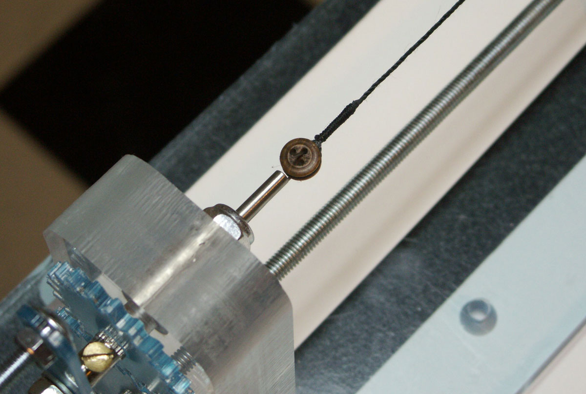
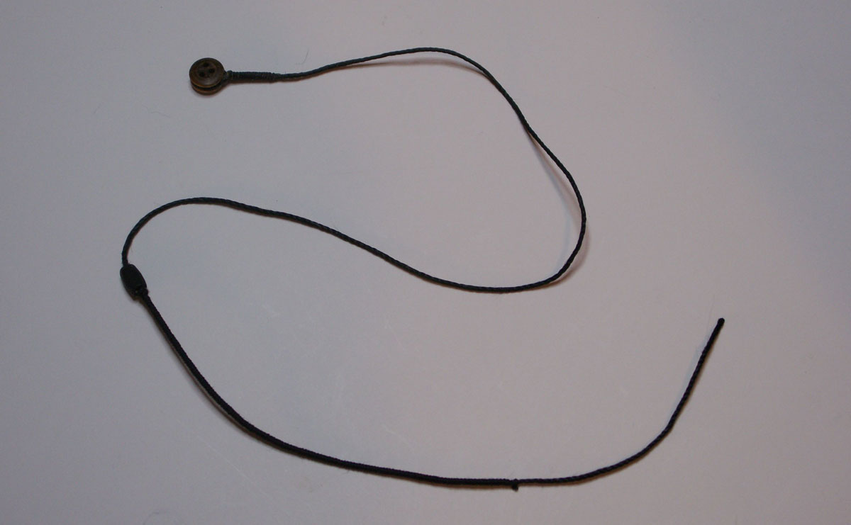
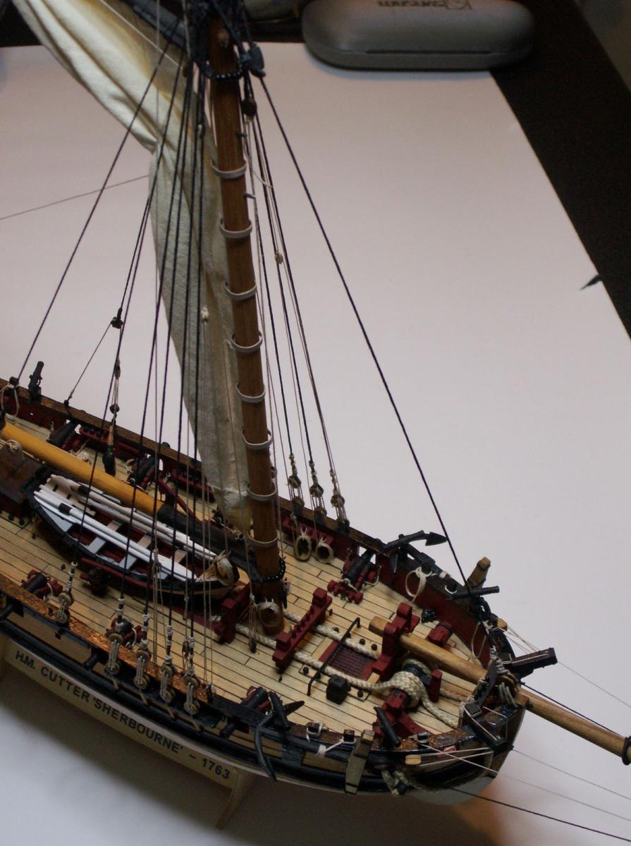
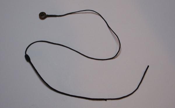
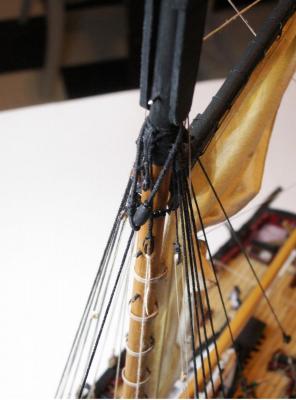
The forestay, for which I used .50mm thread, took some while to make as measurement of its various parts was somewhat critical. In total, it has to be of sufficient length to be seized around the large deadeye at its lower end then pass round the mast, in a large bight, at its upper before being seized to itself below the mouse. When I had decided on the length, I first turned in the deadeye. I should point out here that I used the large three-hole deadeye provided in the kit, rather than the five hole one as shown for the Alert, which seems to have been the more usual. None of the pictures in the AOTS book appear to show a three-hole deadeye for the forestay of the cutters depicted, so this looks to be an error on the part of the kit manufacturers, who seem to have just made the deadeye of a larger size than those used for the shrouds – without considering whether it was historically correct. Had I seriously thought about it earlier I would have lengthened the top of the stem, as I believe others have done, and drilled the five holes. The corresponding five-hole deadeye would also have had to be made, as I have only ever seen three-holed ones sold as accessories. However, by the time I was considering the forestay the bow was finished with the top rail, various items of head rigging and the catheads, all in place. The latter especially, with their proximity to the stem, made it impossible to gain access with a saw to cut off the stem top, without the danger of inflicting serious damage. I therefore decided to leave well alone – and compensated to some extent, by increasing the size of the lanyard. (In hindsight, I would advise anyone contemplating building the kit to consider this problem well before they actually get to the point of doing it!) Anyway, following that slight digression, I’ll return to the forestay itself. The first thing I considered at the upper end was the ‘mouse’, as it is called, and its position on the stay. The function of the mouse was to prevent the bight of the stay around the mast from closing. It was made from a suitably-sized piece of wooden dowel, shaped and then painted matt black, before being drilled with a hole approximately the same size as the stay. Positioning it on the stay was a bit tricky and I had to measure the latter at least twice (the deadeye being held at approximately the right height from the stem, with a temporary lanyard) before marking the position with self-closing tweezers. Then with the stay off the model I threaded the mouse to the position of the tweezers, having spread a small amount of glue there beforehand. When dry, I could then seize the length of the stay above the mouse. The seizing of course prevents chafe where the stay passes around the mast and my (or rather Alexey Dumanoff’s) machine did it in a matter of minutes giving a nice, even seizing over the entire length. I then passed the finished end around the mast, doubling it back on itself below the mouse, fixed it with spot of glue, and then applied a second smaller seizing to the short end by hand. That done to my satisaction, I removed the temporary lanyard and replaced it with a .50mm length that had been waxed. Before passing the lanyard, it was important to take any twist out of the stay, when waxing it, so that the deadeye faced the right direction. When threading the lanyard through both deadeye and stem, I also found it necessary to pass my waxed finger and thumb over it following every pass though the holes, since the act of threading tended to make some of the hairs stand up again. When all the holes were taken up, I pulled all taught with two pairs of tweezers, and fastened the lanyard off above the deadeye in the normal way. Overall I am pleased with the result, although in retrospect I think I could have made the eye just a little bigger. I apologise for the clarity of a couple of the photographs – I blame it on lack of daylight in these northern climes! Next time: the preventer stay, and topgallant stay.

-
Eamonn, Thanks for the photo – nice work. Btw, I take it that's the big bumper autumn edition of, ehem, P,P and C? Looks like some interesting in depth articles there.
- 1,039 replies
-
- 2
-

-
- ballahoo
- caldercraft
- (and 2 more)
-
Eamonn, Looking very nice and don't those open cabin doors just invite you to go below, and share a glass with the skipper? I think you've done a good job on the deadeyes and channels – I say 'think' as the photo is at a bit of a sharp angle to tell exactly. Any chance of one more broadside, er, on? As for the clamps, I wouldn't know.
- 1,039 replies
-
- 1
-
-
- ballahoo
- caldercraft
- (and 2 more)
-
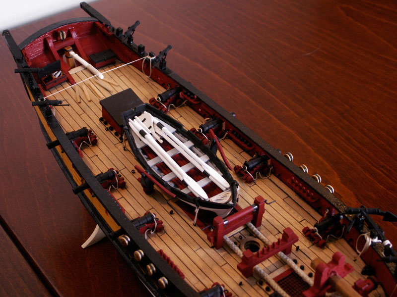
Tony, On my Sherbourne, there is more space between the companion and the end of the tiller than you might think from the earlier photo. This one perhaps shows it better: The after end of the roof also lifts, so there should be enough space for the commander to access his cabin should you want to have the doors facing aft. Just a thought. It would also be interesting to hear what you find out re. your visit to the Science Museum.

- 6 replies
-
- 4
-
-
- Sherbourne
- tiller
- (and 1 more)
-
Tony, No need to apologise, after all your model is your model – and very good she looks too. The roof of my companion slopes down from the aft to the fore side. The forward end is level with the caprail, the after is a little above it, but not by much. I noticed that the positions of the scuttle and the companion on your Sherbourne look rather close together, so wouldn't cutting 5mm off the bottom of the companion, mean that the doors would hit the forward hatch? If you shifted them both forward, and there looks to be space for it, I think that might get over both this problem and the accomodating of the tiller. I agree, perhaps your companion does look a little high. (I remember I did try to keep all the deck furniture as low as possible – the boat is the highest – so as not to impede the boom.) As you can see, I omitted the hatch altogether and replaced it with the companion, just aft of the boat, giving rather more deck space. It may not have been on the original plans, but I thought that the entrance to the commander's cabin also needed a little more refinement. (Perhaps it was on the 'as fitted' drawings!)
- 6 replies
-
- 2
-
-
- Sherbourne
- tiller
- (and 1 more)
-
Tony, Do what I did, and as you suggest, and scrap the after scuttle. Place the companionway where it would have been and you have ample room for a longer tiller. The tiller for the Alert was 10' long and I used this measurement, scaling it of course to 1:64, when replacing the tiller on my Sherbourne. The kit tiller is far too short, and in any case it should have a tenon joint with the rudder head, which is how mine fits, rather than the odd arrangement of the one provided. In passing, and having sailed and helmed on a cutter (actually Jolie Brise) fitted with one, I can tell you that better leverage is obtained with a longer tiller, allied with deck treads.
- 6 replies
-
- 1
-
-
- Sherbourne
- tiller
- (and 1 more)
-
Ken, I'm not sure that's quite true, as the artists who painted these battle and other scenes from the eighteenth/nineteenth centuries, were masters of their art. Don't forget that 'back in the day', the RN and the British population were quite used to such feats by their navy quite frequently and were expecting accuracy in reporting of events, be it in the newspapers or on canvas. They were no less discerning than people are today. So, far from navies not being 'too concerned about the small details of their ships', I would suggest the opposite was the case. Individual naval officers who served on the ships depicted certainly were and could be relied upon to ensure the technicalities were correct, particularly if the painting in question had been commissioned by them from the artist. This was quite common after a decisive action which the officer wanted portrayed on canvas for posterity. I'm not sure many artists worked from the beach, they wouldn't have seen much in any case, but from their studios. They would most likely have been aided by other drawings, paintings and other information, backed up by the input of the naval officers. Some of the artists had also been seamen themselves, so would have instinctively known many aspects of what they were painting.
-
Eamonn, Yes, the forestay next, which will take a little thinking about. I've already cut the stay to length – with enough over to seize around the deadeye at the bow and pass round the masthead, and bearing in mind that the latter end goes round itself below the mouse, and is then seized in an eye. All the top end, above the mouse, will be wormed. I've nearly finished making the latter, out of a small piece of dowel, and the stay will pass through and be glued to it at the appropriate point. The deadeye is already seized at the lower end. Anyway more about that in the next thrilling instalment of my log... I made the strops for the deadeyes out of suitably-sized wire and blackened. I didn't like the kit supplied ones and I suspect, from your question, you don't either! They are probably the same fitting on both models. Mine look much better, so I would suggest you do the same. Tony, I kept my rail, as you see, as I intend to belay the square sail sheets for the topsail and topgallant there. These were/are normally belayed at the foot of the masts – as they have been on the vessels I have sailed on. I've added five belaying pins in the rail for that purpose, the two outer ones will take the sheets of the topgallant, the next ones in those for the topsail. The centre one I'm not quite sure of yet, but possibly the staysail halliard. So, I have a shrewd suspicion my galley chimney will be staying where it is!
-
Eamonn, You've made me feel a whole lot better! Just mentally checked the angles of the sheet and sail, and you're right – it doesn't seem likely it would catch but, as you know, anything can happen at sea! I had thought of an angled flue pipe under the deck too. (Actually the sheet horse is heated by the stove, through a special connection, so that the crew can warm their hands in the winter!)
-
Hi Tony, Thanks for the kind words and it's nice to know my Sherbourne is viewed as an 'educational tool'. Thanks also for the 'likes' guys. As regards galley chimney, the layout of the deck as provided in the kit, doesn't really leave much option as to where to place the chimney. As far as I see it, it can go either side of the fore hatch, or not be there at all. I thought it rather a shame to leave such a feature off, so to the side it went, illogical though this might seem – and I have to agree there is a certain amount of 'artistic licence' here. I haven't found a reference to any 'side mounted' stoves yet, but I live in hope! In my mind's eye, the galley stove is to starboard of the hatch, it's weight offset to larboard by increased ballast or stores! Implausible – probably, but perhaps not impossible.
-
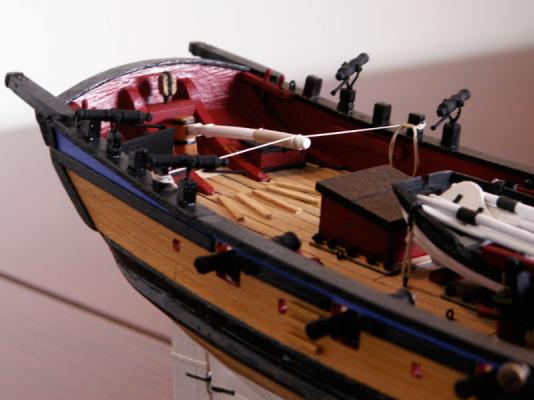
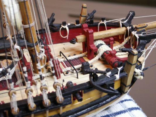
Hipexec, Thank you! The first item of rigging forward of the mast is the forestay, but there is one feature on the foredeck that is perhaps best put in place before fitting it, since access might be a little difficult afterwards. This is the staysail ‘horse’, which runs across the deck over the fore hatch and which takes the lower block of the staysail sheet. The horse is not included in the kit but I think one should really be fitted, otherwise the foresail will not realistically operate in practice. I wasn’t able to find a drawing from the period, and strangely enough the AOTS book on the Alert doesn’t show one fitted on either, so I decided to make one which resembled a cast iron fitting. I am sure there may have been wooden examples, but I reasoned that if other equipment such as guns, anchors and various other were of cast iron, why not the horse? Fashioned out of a suitable metal rod, the ends of which were bent at right angles to the main bar, it was then simply glued into two holes drilled in the deck and at a suitable height. Its positioning was somewhat critical, having to be far enough toward the bow so as not to impede the operation of the foremost guns, yet not so much that the hatch across which it fits, couldn’t be lifted off – and, crucially, it wouldn’t work with the sail. I think I have it about right. This particular area of the deck, however, is somewhat crowded – and I would be the first to admit that the sheet, when in operation, could quite possibly foul my nice galley chimney, especially when on the larboard tack! I suppose I could move the latter, but relocating it somewhere else might be problematic. Anyway, here is the horse in position: Next time: the forestay.
-
Shihawke, The former curator of the ship, Peter Goodwin, in his 101 Questions and Answers about HMS Victory (the book has had various titles – mine is entitled 'Countdown to Victory') gives the amount of rigging as 26 miles in total, on the actual ship. I don't know how much that would work out to on the average model. Goodwin also mentions that there are approximately 768 blocks in the rigging alone, the largest being 26" in length, the smallest 6". I don't know if you have them, but if you are building a model of the Victory, you will find two books indispensible: 1. 'The Anatomy of Nelson's Ships' by C. Nepean Longridge. Much of the information here is contained in the text, the book originally being published in the late forties I think, with several reprints since. It is really Longridge's account of the building of his 1:48 scale model that was on display in the Science Museum until a short while ago, and which has been discussed before on MSW. The book is still considered almost as the 'bible' for Victory builders! 2. 'The 100 gun Ship Victory' by John McKay, in the Anatomy of the Ship series. This book, by comparison, has many useful diagrams and a table at the back listing all rigging circumferences, block sizes, etc. It is perhaps a little more 'user friendly' being easier to find the information regarding a particular block or piece of rigging. Of course how much of the rigging you wish to include is up to you, but I think you will have to compromise!
-
Eamonn, The lamp has the name 'Hansy' and I bought it from Clas Ohlson, the shop for buying practically anything in Sweden! I believe it is also made over here, so I'm not sure you would be able to get it in Ireland. Anway, here is the page from their online catalogue (obviously,it's the one to the left!) Click on it to get a larger view: http://www.clasohlson.com/se/b/El/Lampor-&-belysning/Arbetsbelysning It has certainly made a big difference, the one I had before being just an ordinary extending-type desk lamp. It didn't have the flexiblity this one has, and is better all round. I'm sure you would be able to get a similar type of lamp where you are, if you look around. Good luck!
- 1,039 replies
-
- 1
-
-
- ballahoo
- caldercraft
- (and 2 more)
-
Hi Eamonn, I agree, she looks great. You're doing a fine job. I think the quality of your work shines through, despite what you say about the camera! Remind me again about the enlarged gunports, was that called for in the instructions, or for some dark idea of your own? For fitting bigger guns, perhaps? I'm sure you've mentioned it somewhere in the log, but then I'd have to go trolling through it... If it makes you feel any better, we have the same weather over here. It's been gray dark and overcast for a couple of weeks now, albeit there are a few brief moments when that round yellow thing in the sky makes a brief appearance. I believe it's called the sun, although I'm not too sure. You'll understand that a good working light is essential up here in these here parts, to get anything done at all in the winter! I have a really good one, fitted with a circular fluorescant tube. This gives a really good light and it has a magnifying feature in the top of the lamp, which works really well. The light is also soft and doesn't give any eye strain, as some lamps do. It also comes with a foot clamp, so you can fix it solidly to any surface. I'm very pleased with it. OK, add over... So, the masts next. They look good by the way, and you'll certainly need them in place to gauge the angle of the chainplates for that extreme rake!
- 1,039 replies
-
- 1
-
-
- ballahoo
- caldercraft
- (and 2 more)
-
Bobstay for bowsprit on Sherbourne?
Stockholm tar replied to tkay11's topic in Masting, rigging and sails
Tony, Well actually, and I hate to disagree with you, but there is what looks like a bobstay rigged – and she is dated 1827! -
Bobstay for bowsprit on Sherbourne?
Stockholm tar replied to tkay11's topic in Masting, rigging and sails
Tony, My gut instinct is that Goodwin doesn't show a bobstay, because there wasn't one - on the particular vessel he is writing about. Personally, I wouldn't have thought he'd have left it off the drawings if one were present. Regarding Petersson, there would seem to be a discrepancy between his drawings, which as you say don't show one, and the 'Science Museum' cutter of 1785 – which he says he based them on – which does! (This further begs the question, can Petersson be trusted 100%?) Further, the earlier pictures of the Hawke, in the AOTS Alert book, show that she didn't have a bobstay either and you mention that the NMM model of the Trial of 1790, like the cutter of 1785, has one fitted. This is interesting and suggests, yet again, that the dates are important here – as with the questions regarding the topgallant backstays and yards. Could it be that around that magical date of the mid 1780's bobstays began to be adopted, with regard to the changes in the rig and caused perhaps by an increase in the upward strain on the bowsprit due to an additional sail area? Michael, your pictures would all seem to be later cutters, where bobstays might be expected. As to the question as to whether Sherbourne had one, again I would say no, since she is one of the earlier cutters like Alert, and the upward pull on the bowsprit probably wasn't so great. I also have a theory that, to a certain extent, both the two martingales and the traveller outhaul on the starboard side, may also have acted partly as bobstays. The lower blocks of all three are situated down on the wale, or at least they are on my Sherbourne, so that the line of all of them point downwards from the bowsprit – suggesting that their combined downward pull might be enough to offset the upward one of the headsails. Any thoughts on that? One other point, perhaps, is that the end of the bowsprit was quite 'busy', with all that was attached there, so would a bobstay have been fitted unless absolutely necessary?- 17 replies
-
- 2
-
-
- Sherbourne
- bobstay
- (and 2 more)
-
Topmast Shrouds for Sherbourne
Stockholm tar replied to tkay11's topic in Masting, rigging and sails
Tony, I am not certain that Sherbourne was actually rigged with topmast backstays, which is probably why they are not shown on the plans (and seemingly something they have got right!). The cutter shown in Petersson's 'Fore and Aft Craft' is based on the model in the Science Museum (or was), which I believe dates from around 1785. Earlier cutters, which of course included the Sherbourne, don't seem have had them due to the positioning of the topgallant mast, abaft the lower mast head. This was thought sufficient support, and thus they were not necessary. Goodwin mentions this in his AOTS book on the Alert and goes on to say that topmast backstays were introduced later (around the 1780's), when the topgallant mast began to be stepped on the fore side of the lower mast head. The length of the upper mast was also lengthened which made them even more necessary. Even then, however, they don't seem to have given much support from aft. In the book, there is a drawing of the Alert on page 104, which shows a ticked line indicating a breast backstay, ie. on each side of the topgallant mast, but he stresses this may or may not have been fitted. Consequently, I don't plan to fit any stays or shrouds to my topgallant mast. I know this looks odd to us, and I queried it myself, when we are used to backstays. However, historically, there doesn't seem to be any evidence for them on cutters of this date. Another oddity is the yards and their method of hoisting, but I won't go into that here. In passing, I'm not surprised that it all changed to 'big ship' practice – presumably because they found it didn't work too well! -
Karl, Thank you for posting those. Some beautiful photos of a beautiful ship.