3DShipWright
-
Posts
249 -
Joined
-
Last visited
6 Followers


Recent Profile Visitors

.thumb.jpg.62d1d69fed1f32364417cb1f9cdeb009.jpg)


-
 Bosy Ivan reacted to a post in a topic:
3D Brig 'Rose' in Blender 3.3x
Bosy Ivan reacted to a post in a topic:
3D Brig 'Rose' in Blender 3.3x
-
Bosy Ivan reacted to a post in a topic:
3D Brig 'Rose' in Blender 3.3x
-
WalrusGuy reacted to a post in a topic:
USF Confederacy in 3D | Blender
-
giampieroricci reacted to a post in a topic:
Nate's PANDORA in 3D
-
3DShipWright reacted to a post in a topic:
Nate's PANDORA in 3D
-
3DShipWright reacted to a post in a topic:
Nate's PANDORA in 3D
-
3DShipWright reacted to a post in a topic:
Nate's PANDORA in 3D
-
3DShipWright reacted to a post in a topic:
Nate's PANDORA in 3D
-
Nate's PANDORA in 3D
3DShipWright replied to 3DShipWright's topic in CAD and 3D Modelling/Drafting Plans with Software
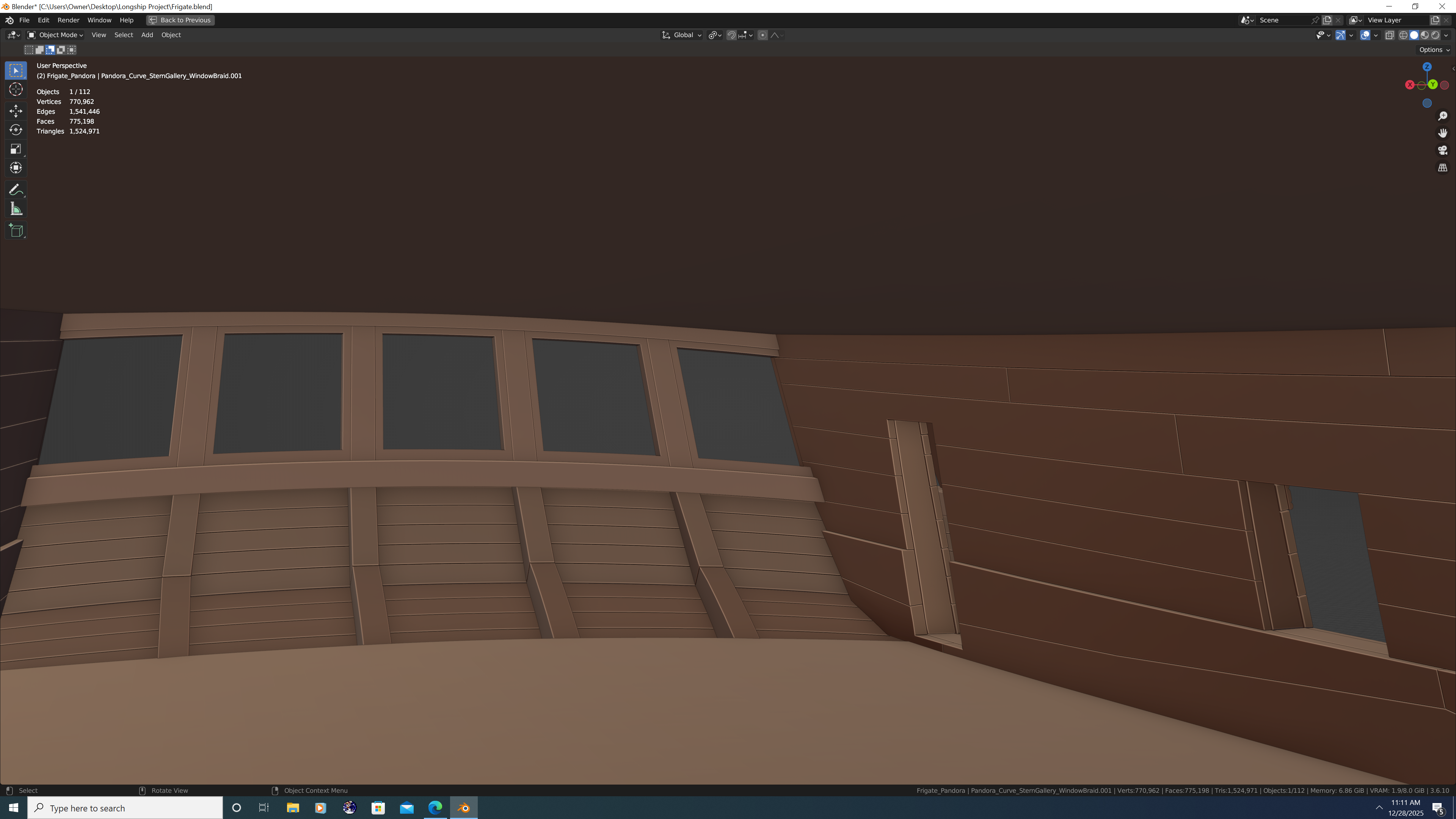
Hey Folks, I could use some help regarding the inside of the great cabin. I'd be much obliged to anyone who can answer any of the below questions. First, an image of the inside as it currently stands... And for clarification, I have not yet modelled the Bench, Bench Step, or Rudder Head Cover as I will have additional questions about those once I get the interior situated. On to my questions: Are the deckhouse doors really only about 4 1/2 feet tall? I think it's perfectly plausible given Pandora was a small frigate and people were shorter back then, but I thought it worth seeking confirmation from you fine folks. Because the interior planking is thinker near the deck clamps, ceilings and waterways (latter not yet modelled) how is a door actually mounted there? The hinges would need to be mounted on an even perch to allow the door to swing open properly, correct? If so, is this accomplished with a large door frame to even things out? Or perhaps the paneling in the great cabin brings the two sections flush? Or perhaps it's a bit of both? (no illustration provided as you get the idea) Speaking of paneling - is my basic assumption that it sits on top of the inner planking correct? Put another way, the internal paneling is in addition to and not in lieu of the internal planking in the aft cabin. Yes? Thank you all in advance, -N.


-
herask reacted to a post in a topic:
Nate's PANDORA in 3D
-
bruce d reacted to a post in a topic:
Nate's PANDORA in 3D
-
CDR_Ret reacted to a post in a topic:
Nate's PANDORA in 3D
-
druxey reacted to a post in a topic:
Nate's PANDORA in 3D
-
3DShipWright reacted to a post in a topic:
Nate's PANDORA in 3D
-
3DShipWright reacted to a post in a topic:
Nate's PANDORA in 3D
-
Jack H reacted to a post in a topic:
Nate's PANDORA in 3D
-
Jack H reacted to a post in a topic:
Nate's PANDORA in 3D
-
Nate's PANDORA in 3D
3DShipWright replied to 3DShipWright's topic in CAD and 3D Modelling/Drafting Plans with Software
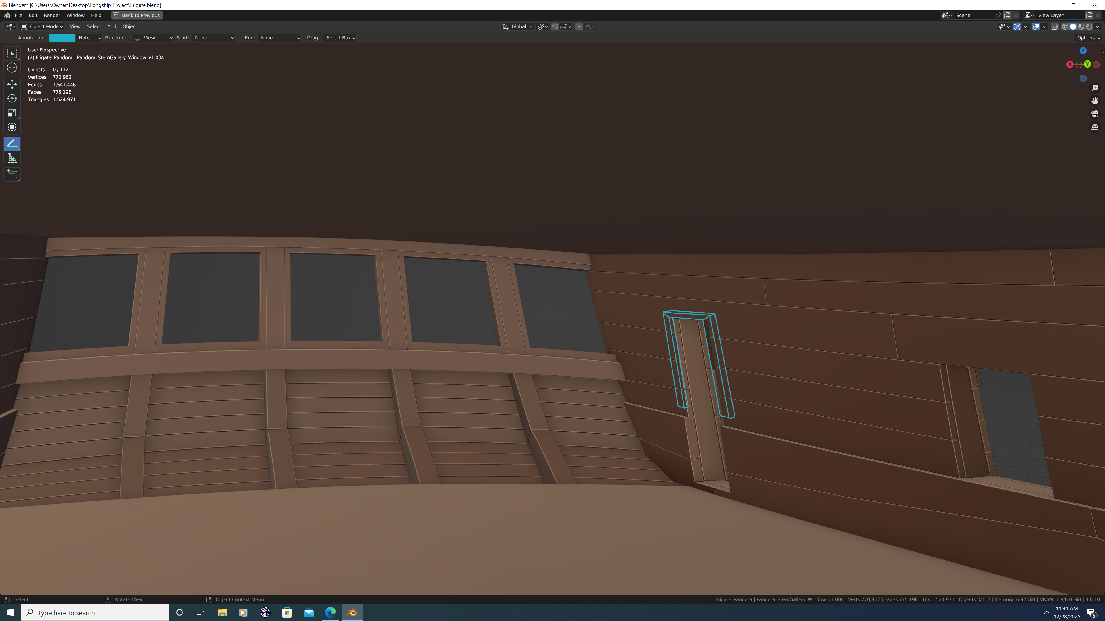
Working on the galleries. I remember one particular ship in the RMG archive of the Porcupine class was illustrated with arched windows on the quarter gallery and I really liked the style. Still working on the drops - getting the shapes correct has been a bit of a crap shoot 🤣🤣 Bad puns aside, I'm getting excited now that some of the more fine details are starting to come out. The internal planking has been completed through the lower deck. The decks themselves are merely placeholders at this point. That's it for now. Happy Holidays All!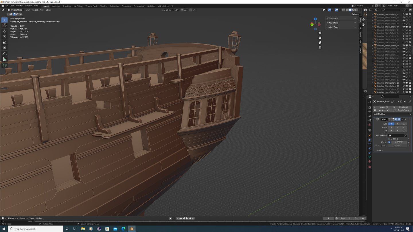


-
Nate's PANDORA in 3D
3DShipWright replied to 3DShipWright's topic in CAD and 3D Modelling/Drafting Plans with Software
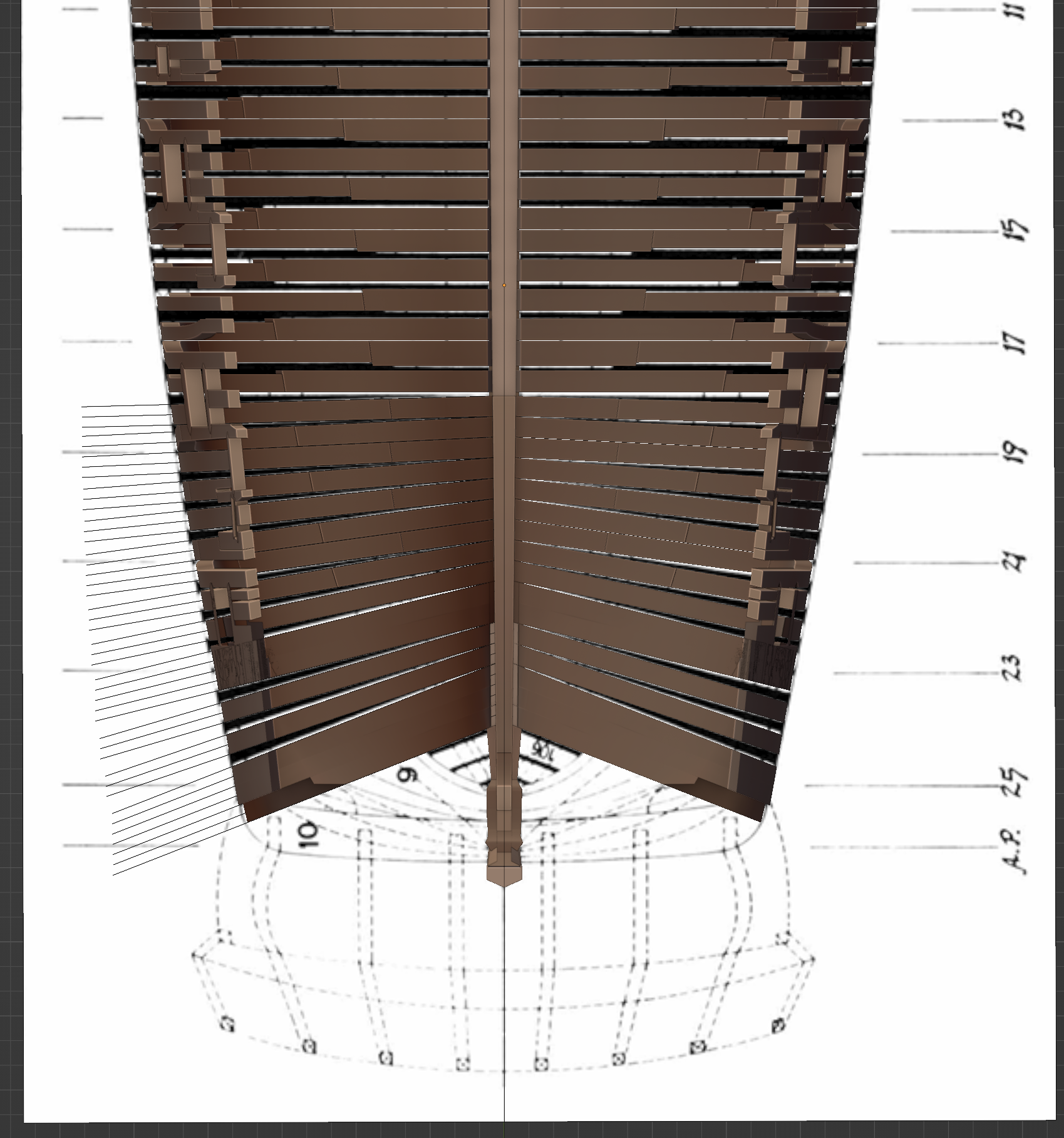
@Pirate adam Thanks Adam, I too agree that the transoms in the AoTS book are somewhat incorrect, albeit for a different reason than the one you provided, which I shall address first: First, let me state that you are correct - a 24-gun ship has four transoms. Sixth-rates and below have no transoms below the Deck Transom, meaning the Deck Transom rests directly upon the fashion piece and any filling cant frames. Above the Deck Transom there are one or more Filling Transoms (I'll come back to this in a moment) and finally, the Wing Transom. However, depending upon the class of ship and the Deck Transom's relative position to the Gun Deck - which refers to the lower deck in Pandora's and Crocodile's case despite there being no guns - the Deck Transom may need to be split. (The image below is of the HMS Eurydice of 1781. HMS Eurydice was cited in the AoTS book as the source material for Pandora's framing profile.) BTW - In case you're wondering why the admiralty plans depict the wing and filling transoms pointing at different angles, it's because the draftsman is trying to depict the sweep of the transoms outward as they curve to follow the crossfall of the deck (shown with how the Wing Transom was drawn), as well as what the centerline of the transoms look like (shown with how the Filling Transoms were drawn), or both (shown with how the Deck Transom was drawn, which is why it is drawn as a wedge shape). In summary, there are four transoms, but because the gun/lower deck bisects the deck transom, there are technically five transom pieces. Bear in mind this is merely my interpretation, but it seems to fit with all available data. Lastly, as said, I did have a few problems with how they did the transoms for Pandora. I'll be back in another post soon to share that part and get your thoughts. Best, -N.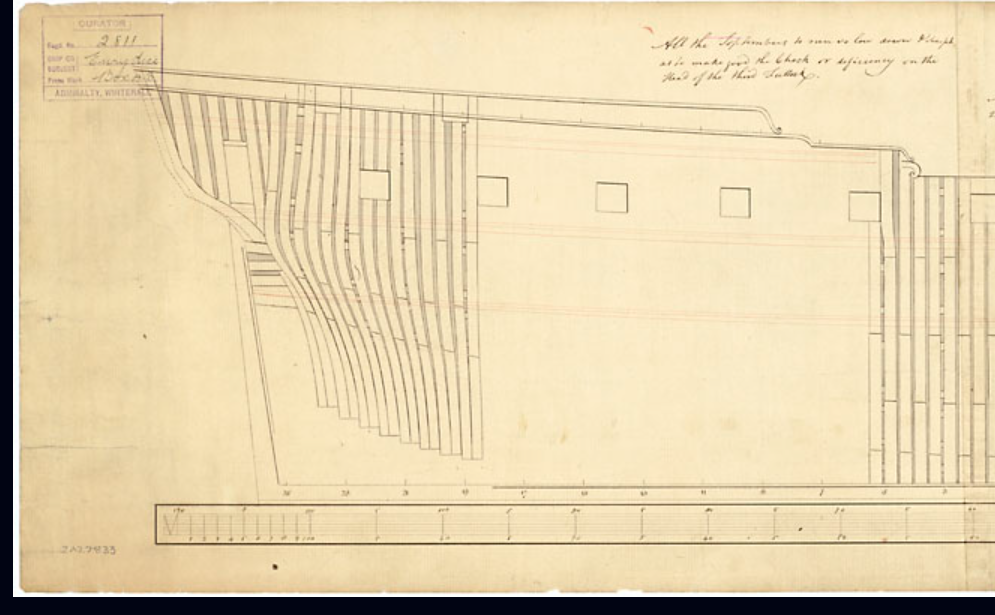
-
Nate's PANDORA in 3D
3DShipWright replied to 3DShipWright's topic in CAD and 3D Modelling/Drafting Plans with Software
Thanks for the insights Trevor. And please know that feedback is always appreciated, and that I truly believe that constructive criticism is just that... constructive. Best Regards, -Nate -
Nate's PANDORA in 3D
3DShipWright replied to 3DShipWright's topic in CAD and 3D Modelling/Drafting Plans with Software
I'm not seeing it. There should be a definite stair stepping effect. Again, there are also no frame pairs depicted, no sweep or sheave port sills or cut-outs, there should be no stepping scarf for the fore cant frames that extends to the outer planking, and several of the aft bollards are depicted as wider than the timbers from which they were carved. Nothing I'm saying should be controversial here: These disposition plans simply cannot possibly be accurate and/or complete. Agreed 100% But you're actually making my point for me: what was the intent of an admiralty disposition plan? Nowhere is it written that those disposition plans were hard and fast blueprints for a ship's framing. The actual framing relies on all those established scantling tables, as well as the available seasoned(or partially seasoned in Pandora's case) timber. And remember, Ron Coleman co-authored the AoTS Pandora book, and he was the curator of the actual Pandora exhibit in Queensland, meaning much of what shaped the designs in the book were pieces of actual wreckage. At the end of the day, I guess it doesn't matter if folks think my framing is historically accurate, it just seems odd to me the way people will cling to the infallibility of NMM/RMG plans with religious conviction, even when they don't hold up to evidence/scrutiny/logic. Best, -Nate -
3DShipWright reacted to a post in a topic:
Nate's PANDORA in 3D
-
3DShipWright reacted to a post in a topic:
Nate's PANDORA in 3D
-
3DShipWright reacted to a post in a topic:
Nate's PANDORA in 3D
-
Nate's PANDORA in 3D
3DShipWright replied to 3DShipWright's topic in CAD and 3D Modelling/Drafting Plans with Software
If I may ask, what discrepancies are you referring to? -
Nate's PANDORA in 3D
3DShipWright replied to 3DShipWright's topic in CAD and 3D Modelling/Drafting Plans with Software
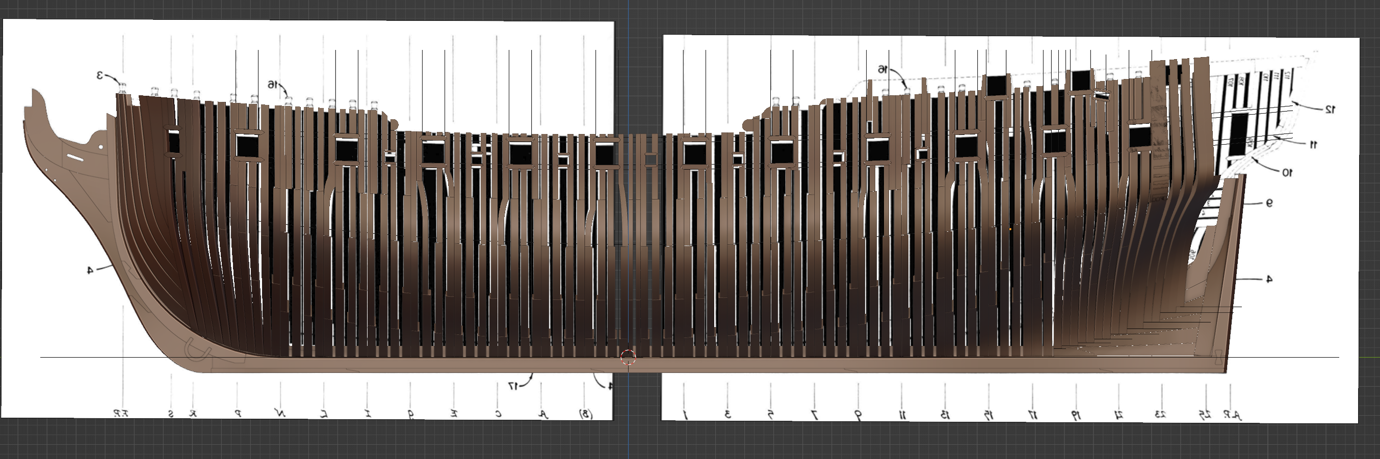
@druxey and @Pirate adam Thank you both for your feedback. I probably should've clarified that it was just the one frame that I wasn't sure about. I'm actually quite confident that the real ship's frames bore a much closer resemblance to how they are depicted the AoTS book than they do any disposition plans on the NMM/RMG site. So one VERY important thing to note when it comes to frames. is that frame disposition plan IS NOT to be interpreted as a comprehensive framing plan. You cannot treat everything from RMG as gospel any more than you can treat diagrams in the AoTS as gospel. This is not to say that these plans are 'wrong' rather, to my eyes they are merely a simplification of the actual frame plan (at least the ones signed by Williams are) In fact, referencing the HMS Sphinx diagram below, there are several obvious examples as to why this plan cannot be the actual frame layout for the ship: The siding of each futtock above the floor timbers do not dither/diminish as they are supposed to in real life. The fact that futtocks get thinner as you go up is well established and their precise proportions documented in various scantling tables (I used shipbuilders repository of 1788 pg. 95-96 if you wish to double check my work. Scantlings of a 24-gun ship at midship (percentages rounded) First futtock of floor timbers 98% Second futtock of first futtock 87% Third futtock of second futtock 95% Fourth futtock of third futtock 97% Top timbers of fourth futtock 99% Crunching these numbers, the top timbers should be approx 77% the width of the floor timbers. This detail is clearly omitted on the Sphinx plan. @druxey this is why the top timbers appear more spread out on my model. There are no cut-outs, nor sills, depicted for either the sweep ports or the sheave ports. This is further proof the RMG frame plans for these smaller ships are not comprehensive The perpendiculars are evenly spaced, which once again is contrary to the established 2-1-1 floor timber arrangement These are just the most obvious reasons the RMH/NMM plans can't be 'as done in real life'. Now, that still begs the question: Where on earth did Pandora's Framework come from? Well, I think Tim McKay did the same thing I have done, that is, derive a frame plan that actually conforms to all documented metrics and scantling data. Lots and lots of math and calculations. I've spent the better part of a year essentially re-designing Pandora from the ground up and I've reached a frame plan that is very close to, but not identical to, what is in the book. Just my two cents. Best, -Nate
-
Nate's PANDORA in 3D
3DShipWright replied to 3DShipWright's topic in CAD and 3D Modelling/Drafting Plans with Software
Good to hear from you Druxey! I hope you're doing well. That particular futtock frame is odd indeed, and the result undoubtably creates a structural weakness beneath gunport #3. Question - when you say 'looks odd' are you simply making an observation, or do you suspect it may be historically incorrect? I ask because I have it modelled the same way it was drawn in the AoTS book (Frame #31, figure B5/1, page 33) But like I said, it seems odd to me as well, so if you've any evidence to refute this drawing, I'd love to have a look at it. Best regards, -N
-
3DShipWright reacted to a post in a topic:
Nate's PANDORA in 3D
-
Nate's PANDORA in 3D
3DShipWright replied to 3DShipWright's topic in CAD and 3D Modelling/Drafting Plans with Software
@Loracs - I'm certainly not opposed to the idea of making a formal tutorial series on ship building in Blender. I've received a handful of requests to do so, be it written or video format. However, I hesitate for a few reasons: My passion is making high-quality digital boats and ships. The key word here is digital. My work has yielded some amazing renders and animations, but they don't translate to physical assets (CNC parts/3D printing) nor even video games due to their high poly count. A majority of folks loose interest right there. Secondly, you're correct, making a tutorial in any format is time consuming. I'd be happy to do it, the problem is each person would want something different, and that's assuming they know blender well enough to follow along. For example, this is a gross simplification of my actual process, step by step: Import the sheer and body half-breadth and plans for the ship you want to build Scale and align them to the global origin of the ship - top-of-rabbet, station (+) - then rotate them to be visible from the orthographic X, Y, or Z axis Add a curve for each station line and use the curve tools to trace each line atop the molded-breadth plan Then position each curve font to back at its appropriate location using the sheer plan Mirror all curves either before or after midship so that all curves are on the same side of the ship. Convert all curves to meshes and then join them into a single object that contains all station lines Ensure each station line has the same number of vertices, and furthermore that the vertices on each station line are equal to one more than the number of strakes on the exterior hull (verts=n+1) Then ensure that the vertices are evenly distributed along the line (the Space function of the Loop Tools add-on in Blender can assist with this) Loft all station lines together (Loft function of Loop Tools add-on). You now have a flat sheet that represents one side of your hull. The result will likely look blocky, so either: Loop cut interpreted station lines between the actual stations, or... Subdivide the mesh using the Sub-serf modifier. Neither method is perfect. The Sub-serf modifier will automatically sooth everything out for you, but it will do so by distorting (shrinking) the original station lines as well as doubling the number of strakes. I prefer to manually loop cut between each station, then smooth out the new interpolated lines using the 'Curve' function of the Loop Tools add-on, but for some weir reason, you actually only select the original stations when doing this, but the function will operate upon the non-selected lines. No idea why it works this way, but it does. Anyway, you get the idea... Thing is if you follow everything I wrote above, it only gets you to this: Summing up - that's my hesitation in doing tutorials. However, I have been working with @CDR_Ret for a couple years now and I think he's got a pretty good grasp on the general flow I'm discussing here. And unlike myself, he has professional experience in technical writing and educational texts. He and I have kicked around the idea of transcribing some of this 'knowledge' if you can call it that, for other aspiring Blender artists. @CDR_Ret - Not to put you on the spot Terry, but what do you think? Knowing what you now know about this process, is the fundamentals of 3D shiprighting in Blender something you think we could throw together for folks? Like I sad in my opening, happy to consider it, just wanna make sure the juice is worth the squeeze. Best wishes to you both, and Happy Thanksgiving to my American compatriots! Nate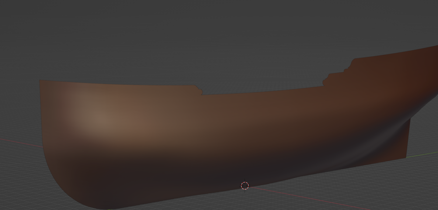
-
Nate's PANDORA in 3D
3DShipWright replied to 3DShipWright's topic in CAD and 3D Modelling/Drafting Plans with Software
Oh good, nice to know I don't have to worry about texturing her then 😆 -
Nate's PANDORA in 3D
3DShipWright replied to 3DShipWright's topic in CAD and 3D Modelling/Drafting Plans with Software
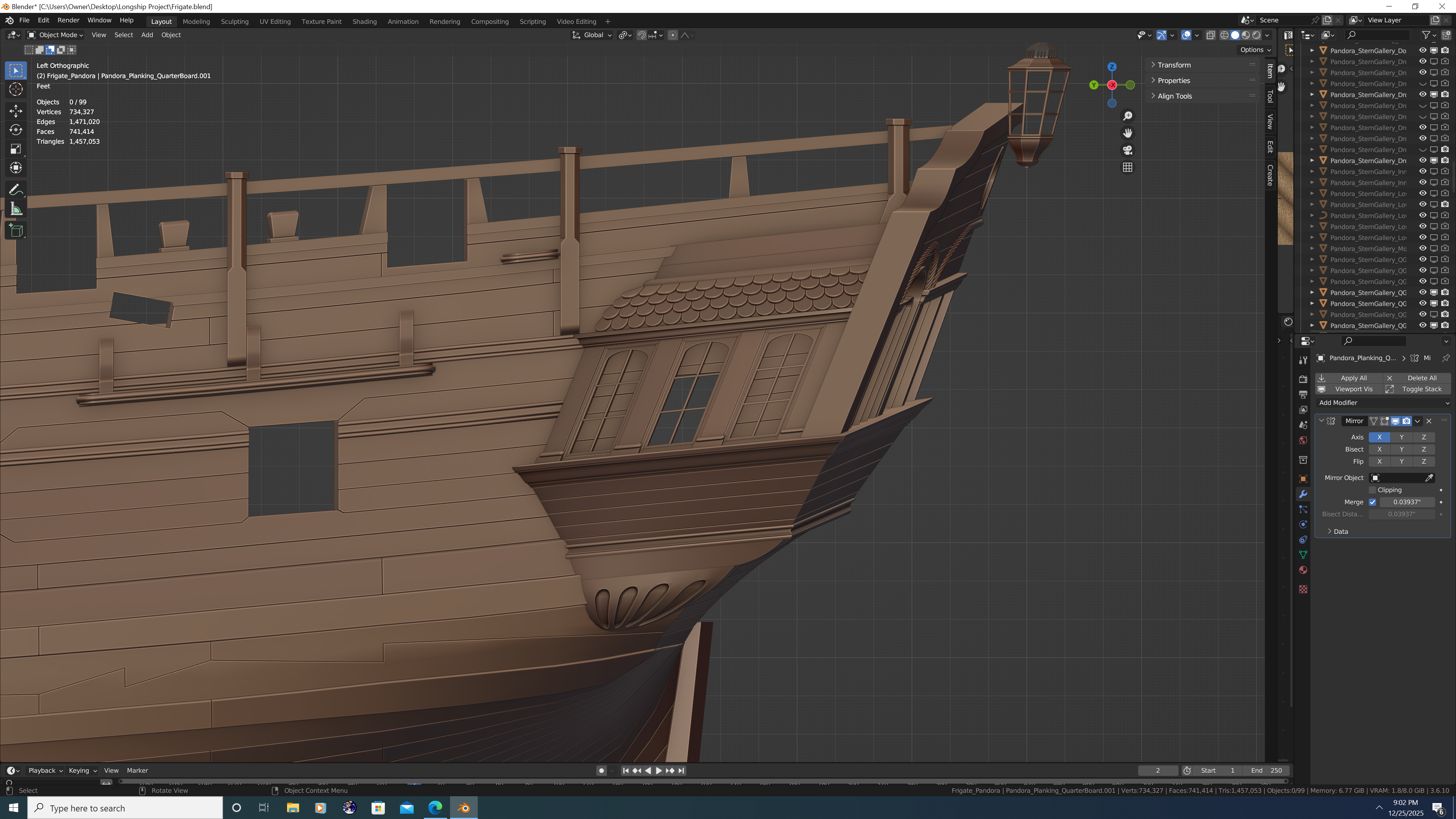
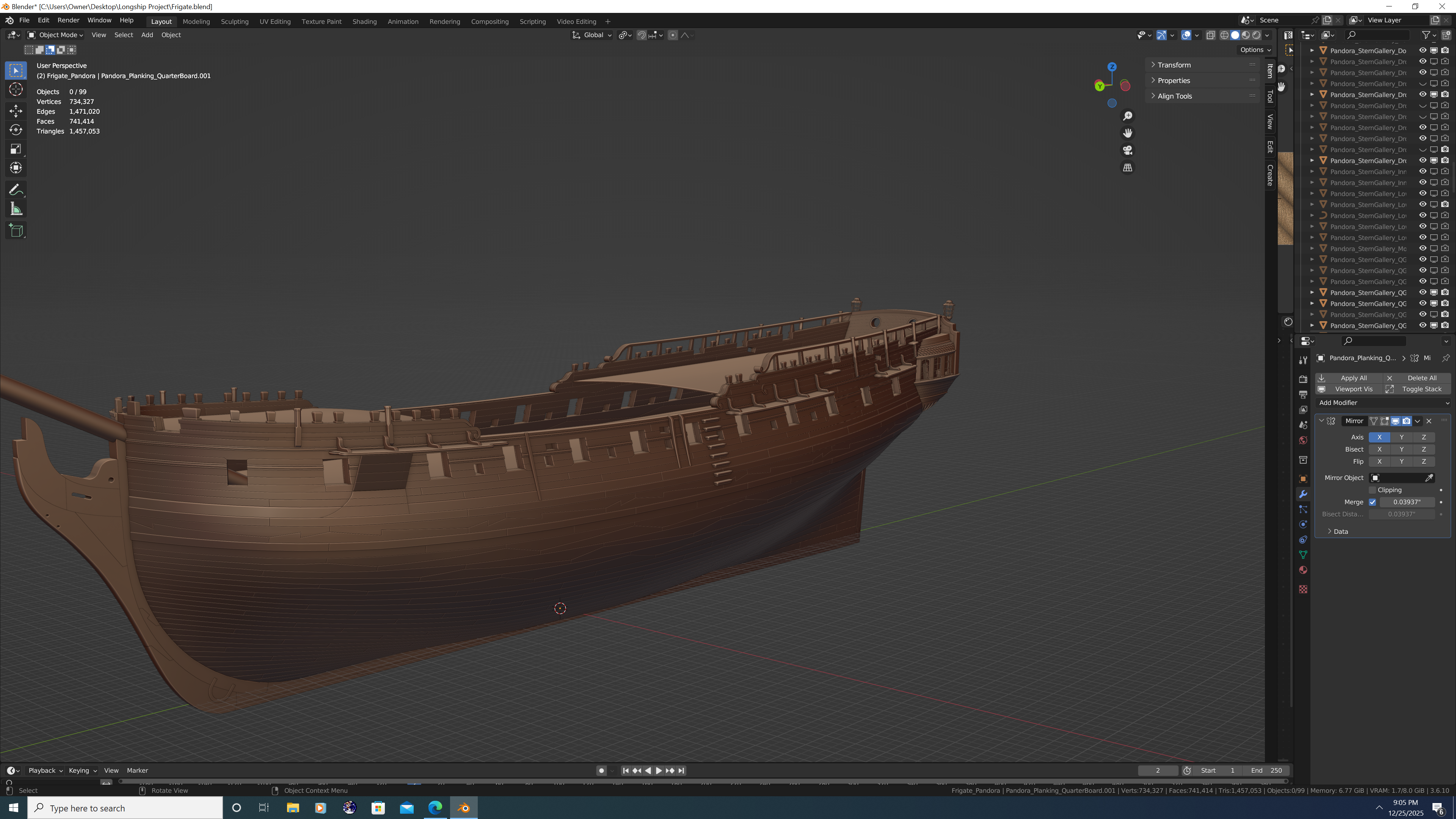
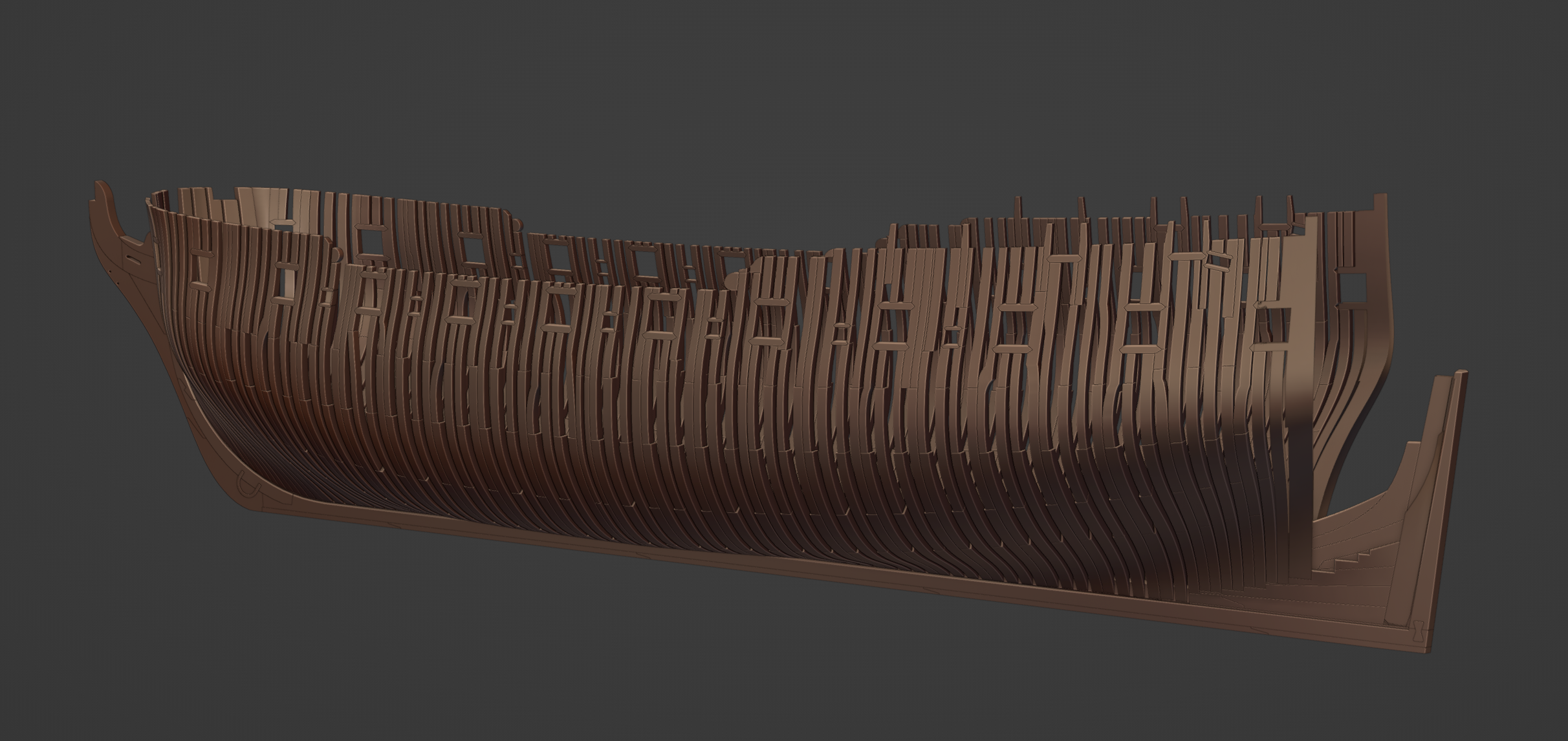
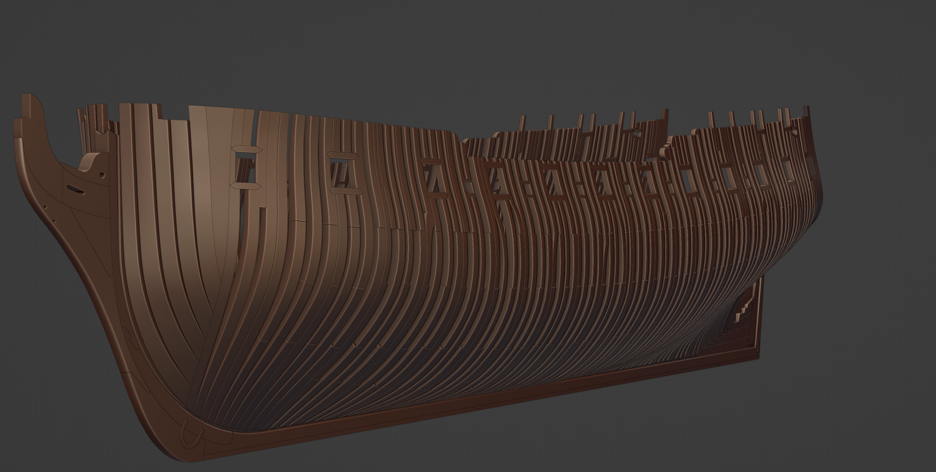
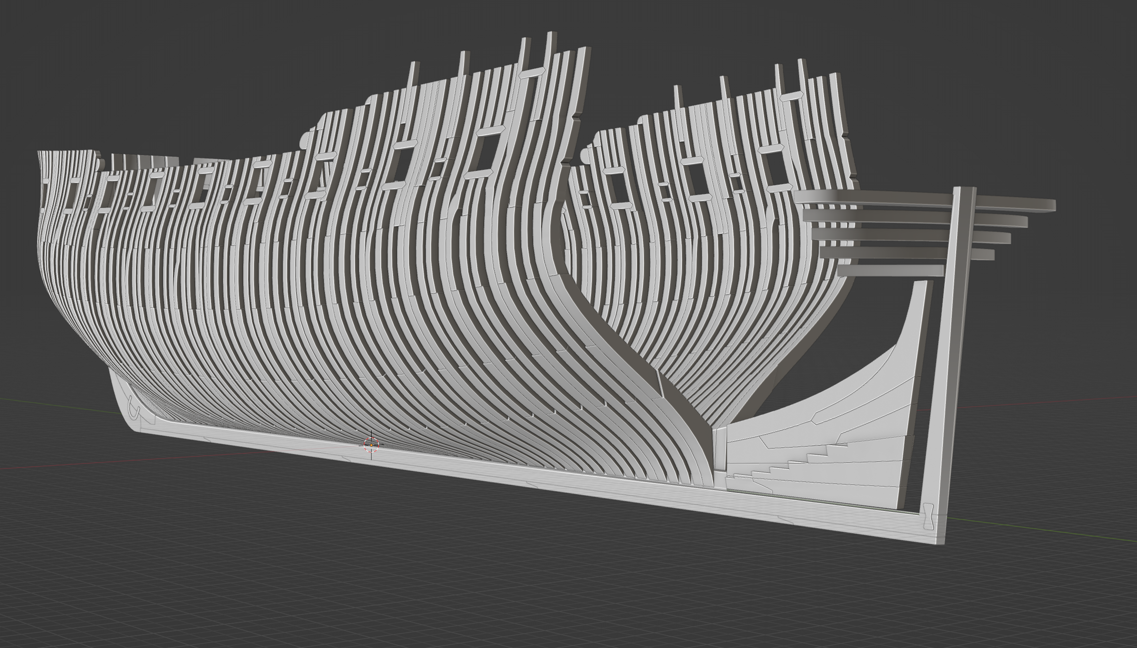
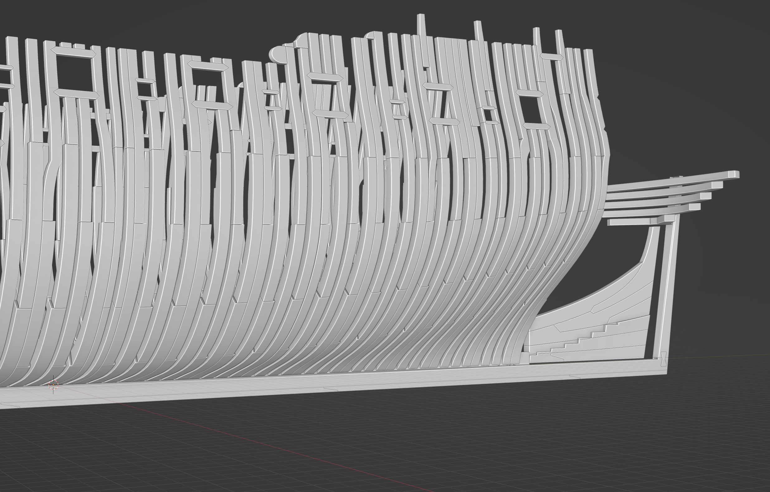
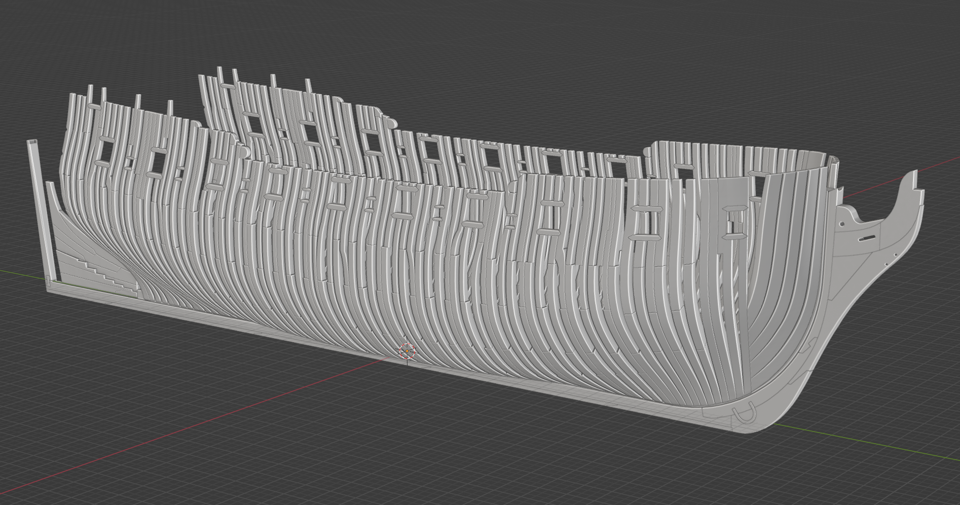
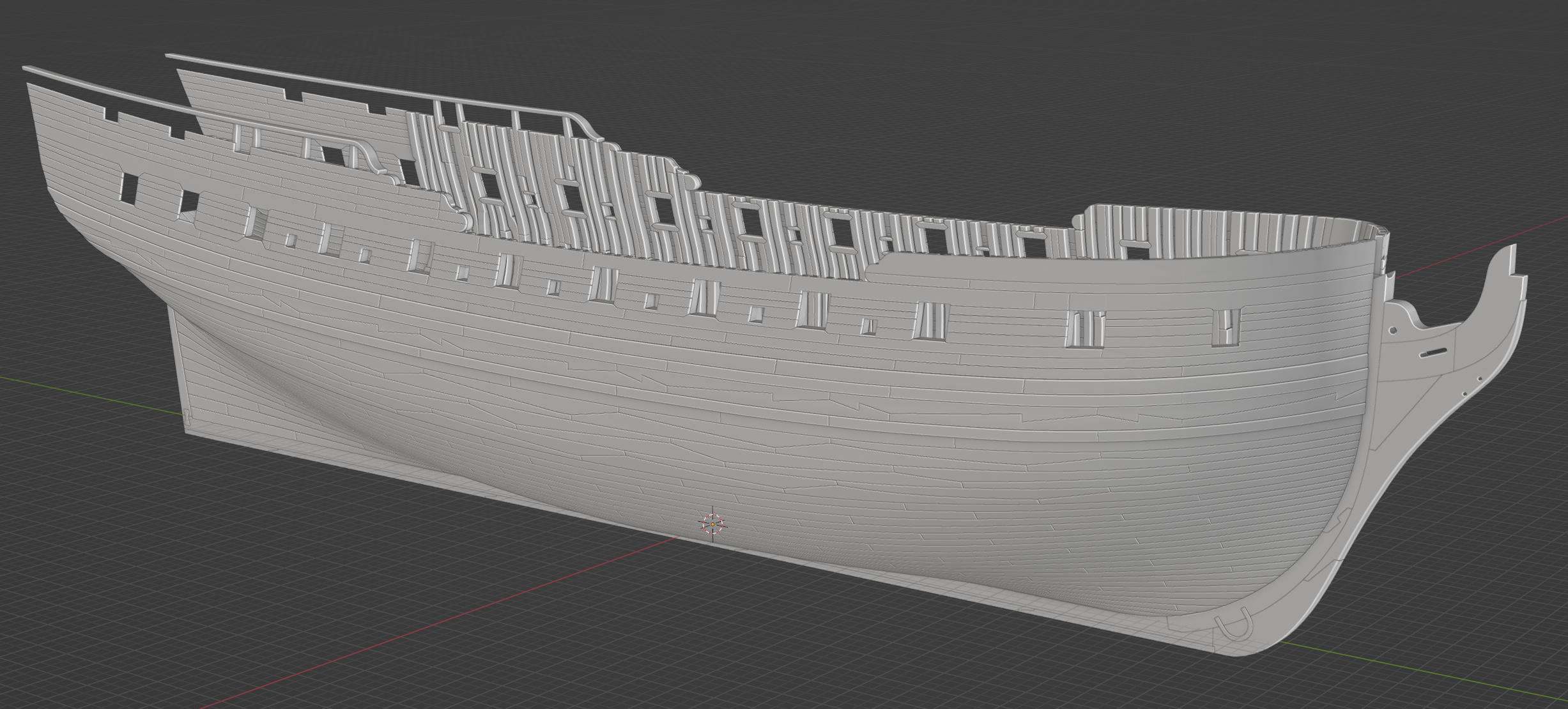
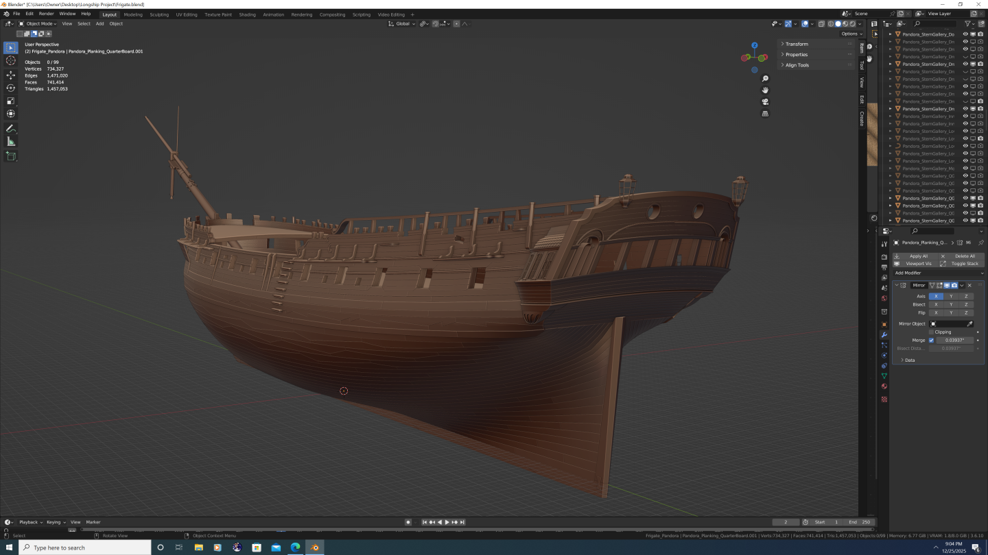
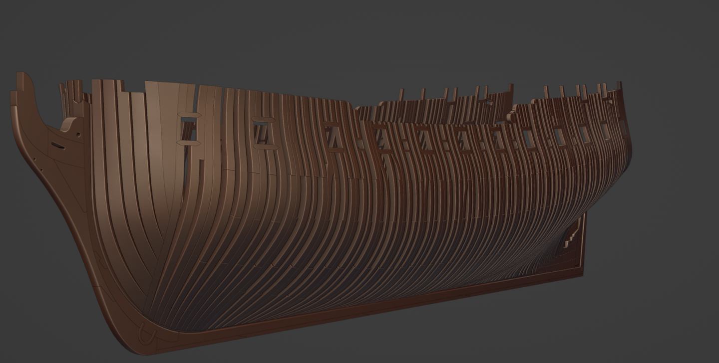
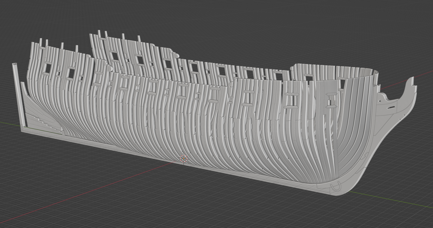
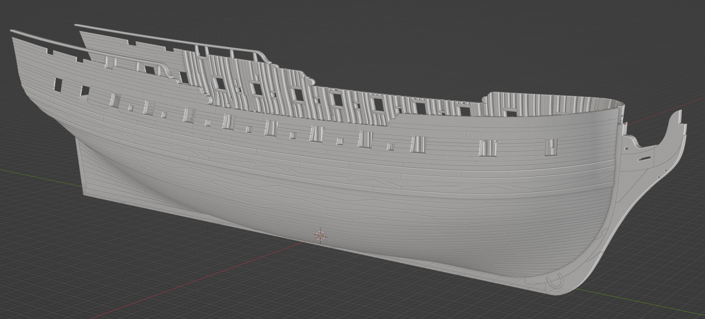
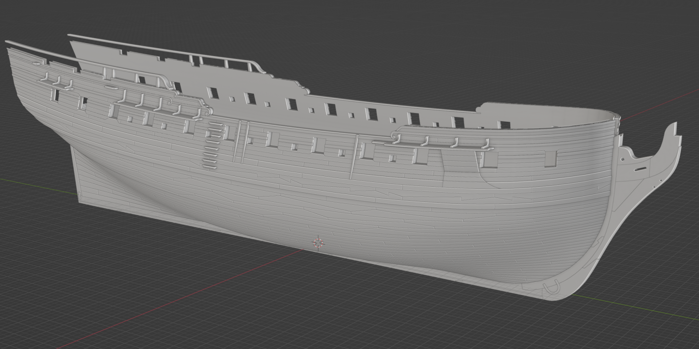
Dusting off my Pandora project for some work on it during the holidays. Here's a few current state images to kick things off...


-
Yet Another Pandora 3D build
3DShipWright replied to herask's topic in CAD and 3D Modelling/Drafting Plans with Software
But where's the nanite foliage, the voxel rendering of every single splinter of wood? Where's the cloth-on-cloth chaos simulations and the over 300 NPC's in each frame? 4/10 - Disappointing. 🤣🤣😋 -
Nate's PANDORA in 3D
3DShipWright replied to 3DShipWright's topic in CAD and 3D Modelling/Drafting Plans with Software
Ahh Pandora's framework: it's been so much fun /s. Kinda like when the progress bar shoots up to 90% and completely stalls

-
Nate's PANDORA in 3D
3DShipWright replied to 3DShipWright's topic in CAD and 3D Modelling/Drafting Plans with Software
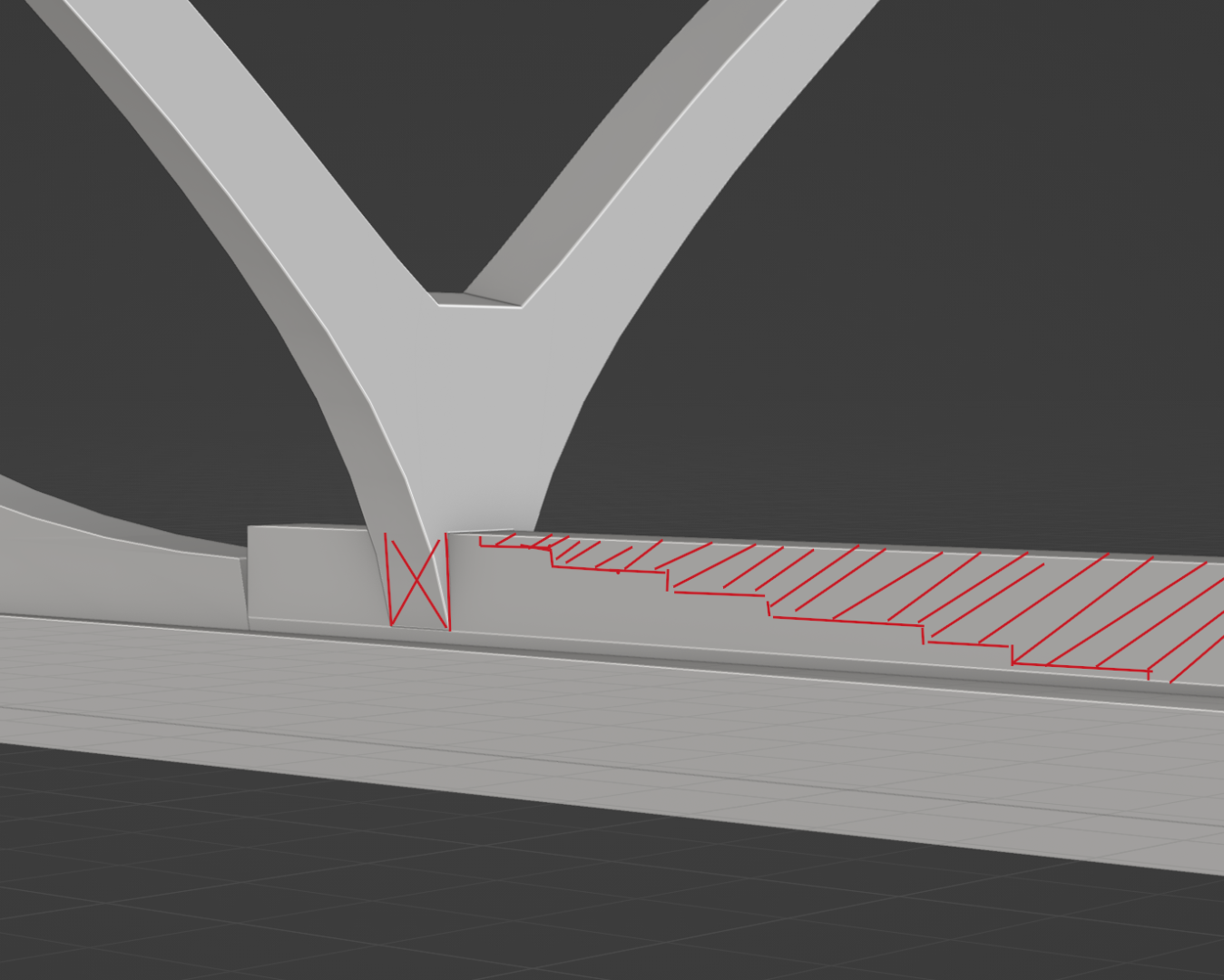
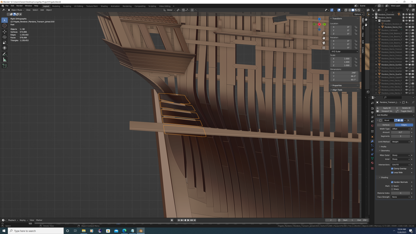
Framing update: prepping for the aft cant frames. Working on the deadwood pieces. Getting the stepping cuts to precisely follow the bearding line has been a challenge. Another challenge is that the siding (room and space) calls for aft cant frames at 10 inches, but that is a measure of the outboard siding. Inboard of the stepped scarf - where the frames abutt the deadwood - is actually smaller, which is why the second frame in each pair on each step appears narrower than the forward partner. The width of the aft frame is not even consistent, rather, it is a mathematical function of the angle. Translated into English... Yuck! Super slow-going, but I hope my attention to detail will be worth it in the end...

-
Yet Another Pandora 3D build
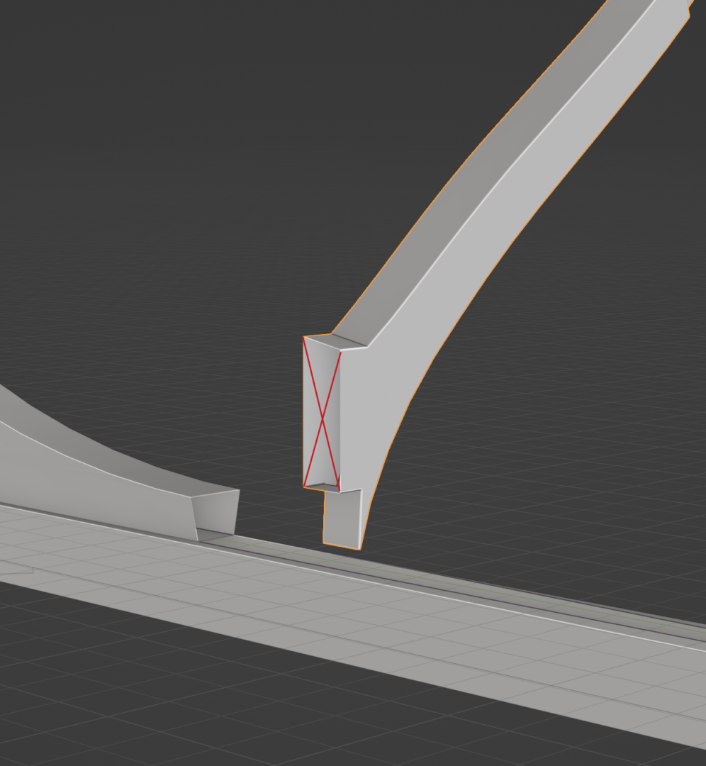
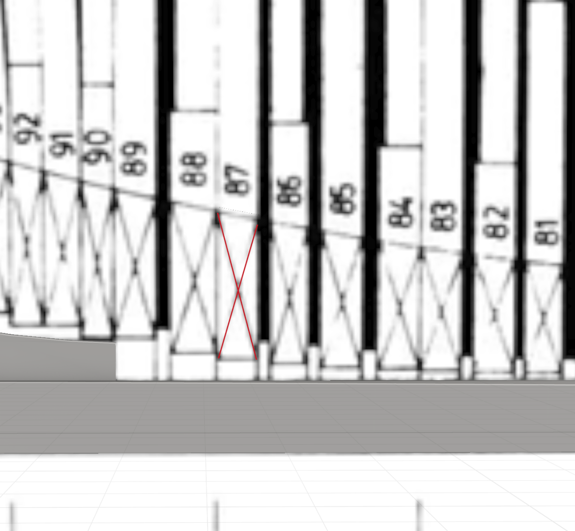
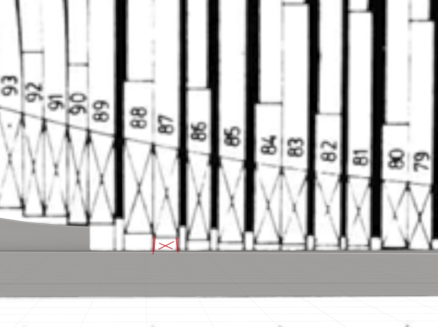
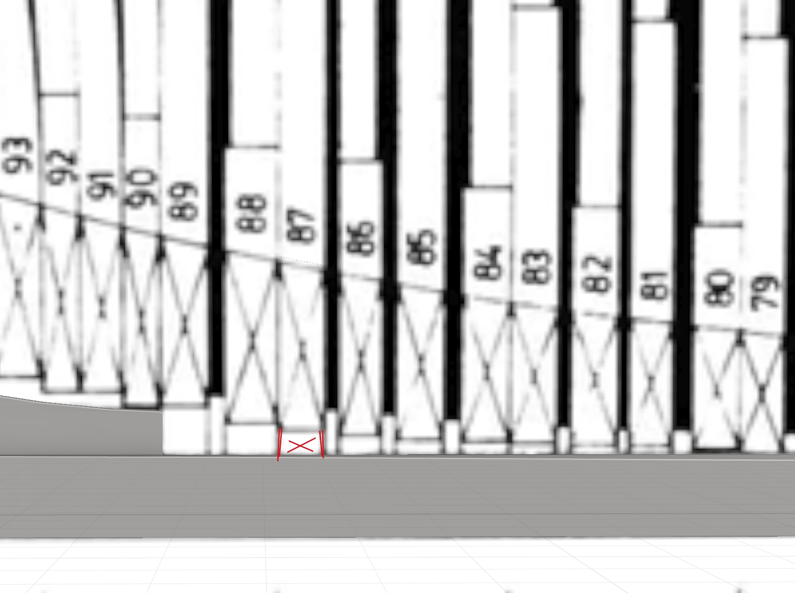
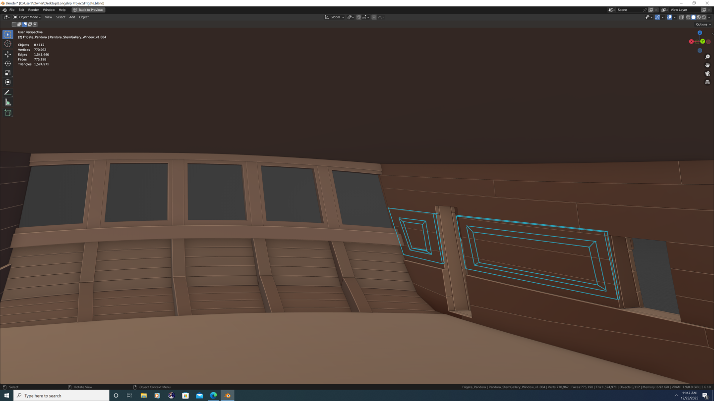
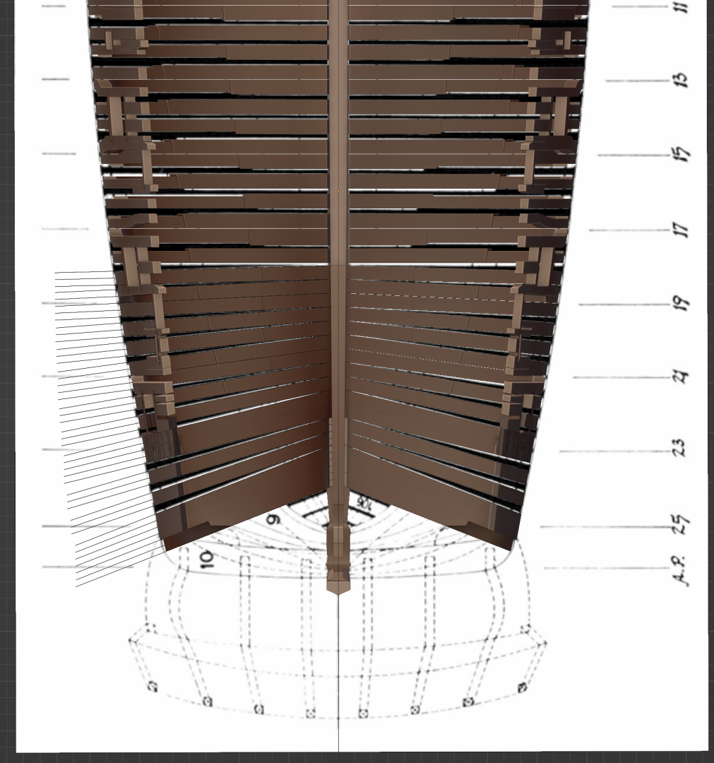
3DShipWright replied to herask's topic in CAD and 3D Modelling/Drafting Plans with Software
Dang you work fast... You're almost caught up to me and I've been at it for half a year now. Anyway, one comment on the frames: In all cases excepth the aft cant frames that rest atop the stepping scarf, the outside of the frames terminate at the top of the rabbet. the rising wood cuts higher and higher into the frames as you move aft, but the actual bottom of the frames remains at the top of the rabbet. This is why technically speaking, the bearding line on Pandora and others is only indistinguishable from the rabbet (top or back rabbet, I can't remember) on the aft deadwood and moving up the apron at the front. I know this may not be hard to understand without visuals, so to illustrate: The red X corresponds to the X on the plans, shown in the next image. It is where the two sides meet were you to bisect it down the middle of the keel Notice the vertical lines on the plans continue down. These represent how the external edges of the frames continue down to the rabbet. And shown again in 3D... (note - the red cutout lines are merely illustrative. When I cut down the rising wood for real, I will account for not only the rising wood, but also the rising chocks, cross-chocks, filling (spacing) chocks, etc.) Of course, if you already have a plan to address everything I just said - feel free to ignore this whole thing. Keep up the awesome work, -Nate