Greg Davis
-
Posts
363 -
Joined
-
Last visited
Content Type
Profiles
Forums
Gallery
Events
Everything posted by Greg Davis
-
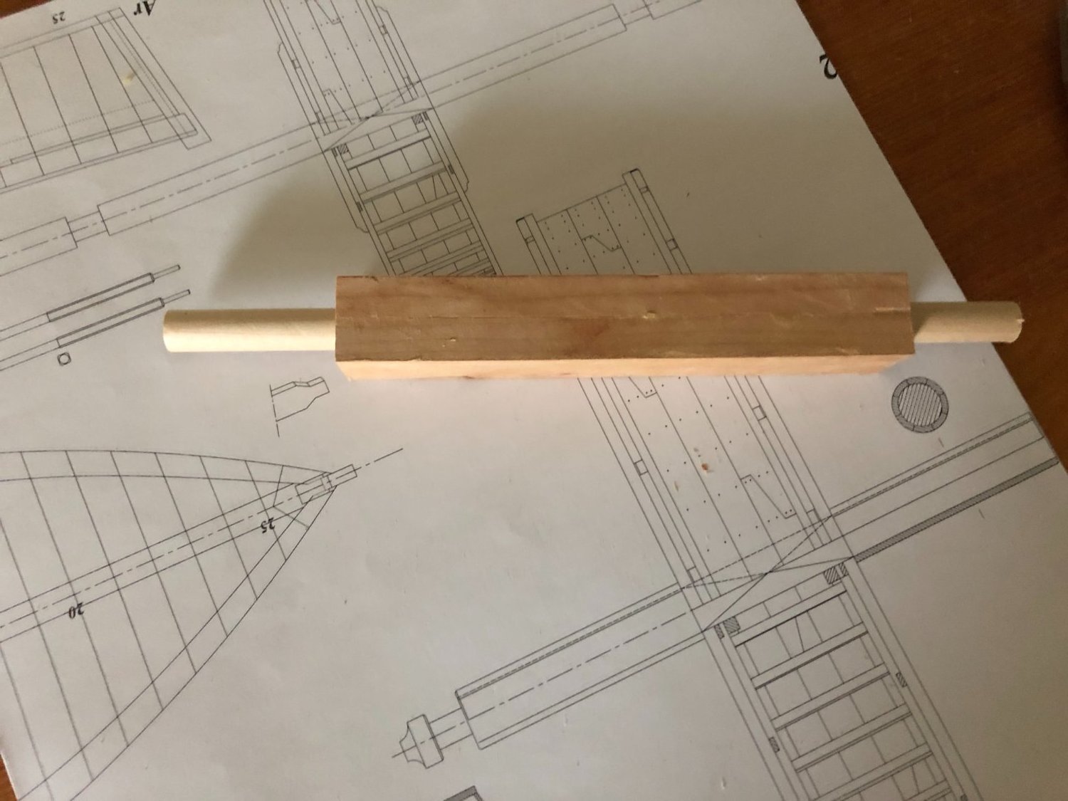
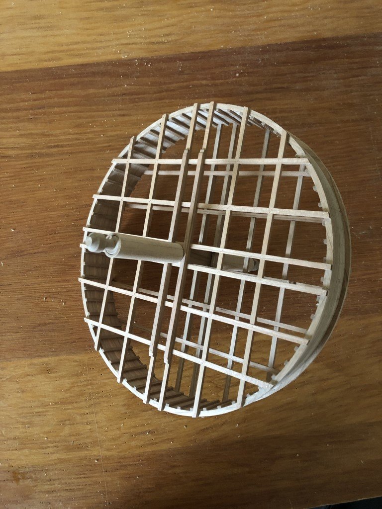
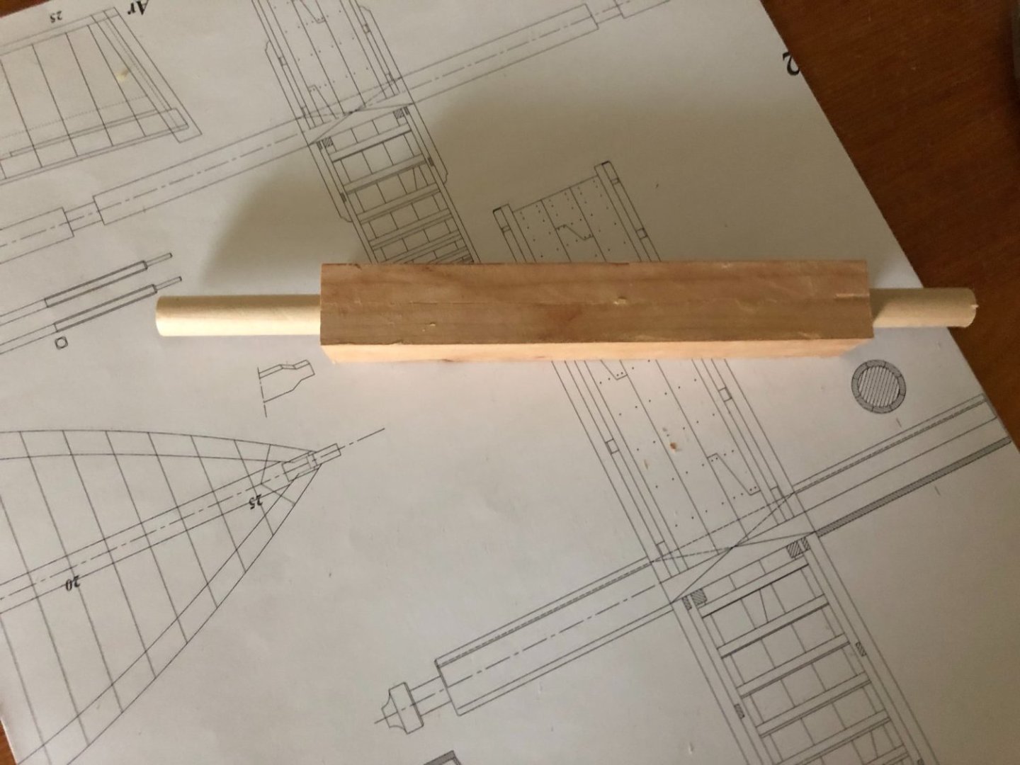
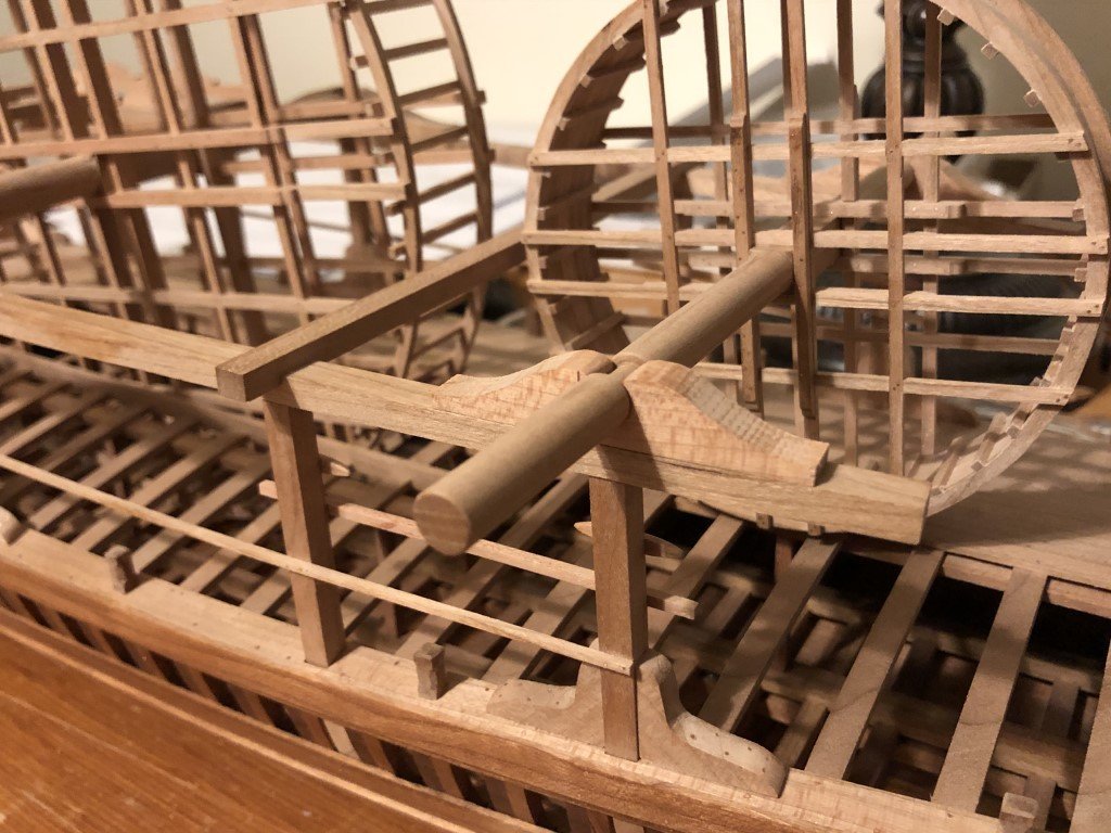
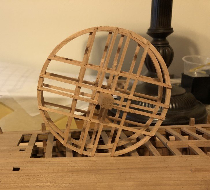
Its been a few days and a few tasks have been completed. I just finished the big wheel structure; so all of the planking fasteners are in place, and after a bit of thought and work the axle doubling is done. At first I was not sure how I was going to make the axle doubling - eight planks evenly spaced about the axle. Then I recalled how I had previously seen capstans and barrels made from built up blanks. This led me to cutting a bunch of wood to a 45 degree angle and then using 8 pieces a blank was produced. Next I drilled out the middle of the blank in a series of steps, the last being with a 3/8" bit - this was the closest I had (but smaller) to the axle diameter. I then passed a 3/8" dowel thru the hole before using a lathe to fashion the outside diameter of the doubling. Once the lathe work was done, two lengths of the resulting cylinder were parted off and removed from the dowel. To finish, I used a tapered dowel covered in sandpaper, spun on a hand held drill, to open the cylinder's hole just enough to slip the doubling onto the axle. A spot of glue and job done! Now it is time to oil the structure and place it onto the superstructure.
-
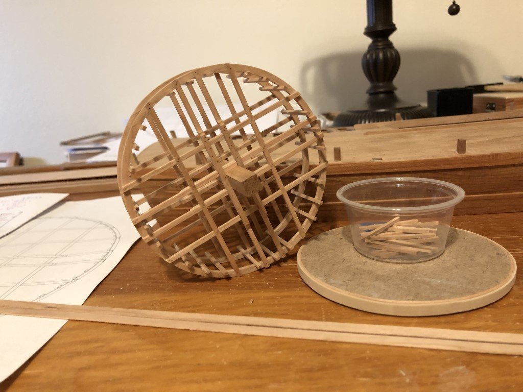
Today I finished the small wheel; i.e., got all of the fasteners in, attached the wheel to its axle, and oiled the assembly. I have also completed the planking on the big wheel. It is now ready for fasteners and finishing.
-
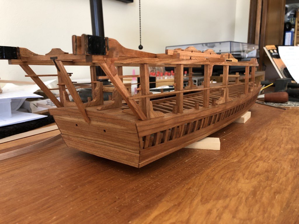
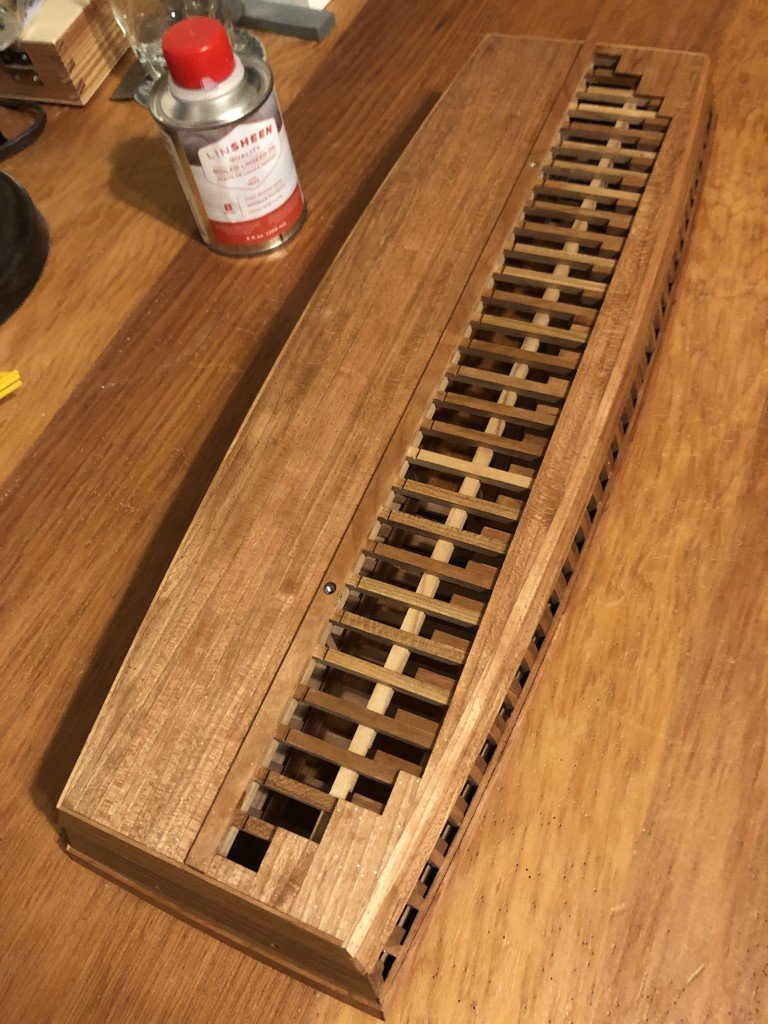
Since my last post, I have added all of the superstructure fasteners and metalwork. Here is the last picture I took before oiling the deck and superstructure: Today I spent nearly 4 hours swabbing linseed oil onto the deck and upper works. I think it is looking pretty nice, and am really looking forward to seeing it with wheels and scoops. In a few days, when completely dry, I can think about adding 6 ring bolts to the deck. I believe the main purpose of these ring bolts was to attach ropes with hooks that could then secure the wheels during transport / anytime one would not want them free to turn. Now my attention will turn to finishing the wheels. Simultaneously, I will start working on the scoop mechanisms. I guess it is also time to select a mounting / display mode for the vessel.
- 199 replies
-
- 11
-

-

-
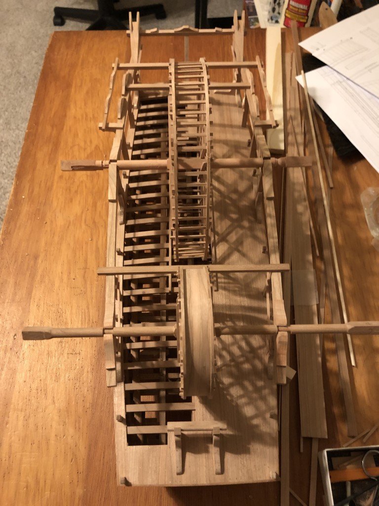
Over the past few days I did make a new set of axles. These will be keepers! Later the big wheel axle will get some doublings to help support the scoop chains. Above you can also see that I am adding the fasteners to the scoop guide components. I've been doing a lot of fasteners lately - guard rails, cleats, foot boards, ... Still quite a few to go on the superstructure, but progress is being made. Here is the new small wheel axle. I've been doing other odds and ends as well; for example all of the small wheel steps have been made flush with the rims and some metal work has been done on the davits.
- 199 replies
-
- 10
-
-
-
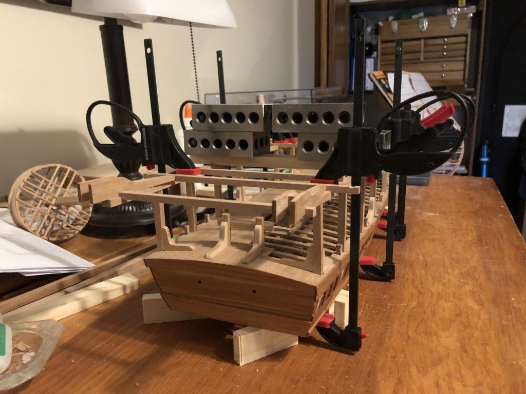
The wheel bearings are complete and firmly attached. Cleats are in place as well - not too easy to see, but they are on the inside of pillars 1,2, 5, and 6. The two wheel axles in these pics are now classified as 'practice pieces' - they were fails, better ones will be made! However, they are being used to check wheel alignment, etc. Looks like everything is going to be were it belongs.
- 199 replies
-
- 14
-
-
-
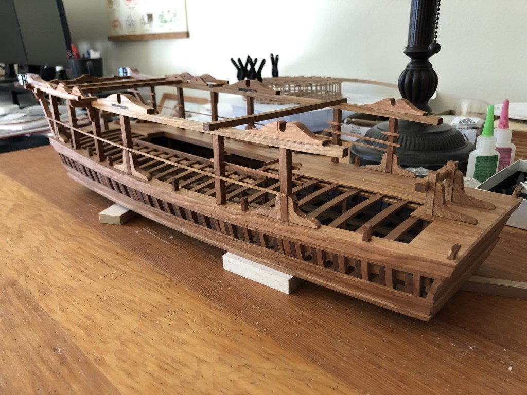
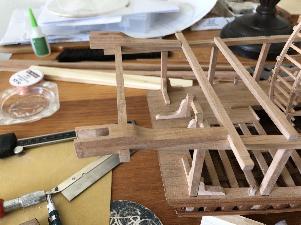
Over the weekend, guardrails and foot boards were added to the superstructure pillars. Also, I finished the last two knees - the ones that fit onto the slanted pillars. For some reason, these knees presented a great deal of difficulty for me to get all the angles right. Quite a few attempts were made before I was able to make a pair that I was willing to attach to the model. Today I began work on the wheel bearings. The big wheel bearings are being done first because they looked to be less complicated than the small wheel bearings. The main challenge being that the bearings have footprints that match the curve in the superstructure carling (i.e., the bases are not rectangular) and the required shape looks to be more pronounced for the small wheel bearings than that for the big wheel bearings. Also, because of the carling / base shape, the recesses in the bearings need to be milled at an angle so that the wheel axles embed properly.
- 199 replies
-
- 11
-
-
-
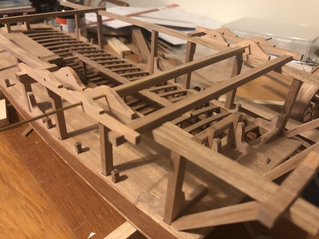
On to a better subject! Today I spent time fabricating components that will support the scoop guides. Here are the parts before installation on the dredger. I connected the smaller roller pin supports onto the external guide beam before drilling holes for the pins. I saw no other reasonable way to have half the hole half above (and half below) the joint. The external guides / beams were then installed. This was easy because the notches placed everything into the right place. I then went to install the inside guides. Note that they come in two sizes with the smaller ones forward; also the smaller ones are not symmetrical, there is a front and a back to these. I set these four guides onto the superstructure to check their fit and at first thought I had done something radically wrong as they looked to be sitting way too low. But then I looked through the holes from one side and was pretty sure I could see through all four. To confirm, I grabbed a piece of stiff wire and passed it thru all four - and yes, all was as it should be! I then use the wire to aid in gluing the inner guides in place. I threaded the wire in place, slid an inside guide into the open space between the superstructure and the exterior guide, spun it over to apply glue, spun it back, and set it in place. Repeat 3 more times and all done. Later, hourglass shaped rollers will be turned to fit between the guides, as well as the pins that keep them in place.
- 199 replies
-
- 13
-
-
-
I keep on feeling stupid for making that mistake, it's not like I don't know of the dangers - unfortunately, I have had family and acquaintances that have lost fingers to table saws and planers.
-
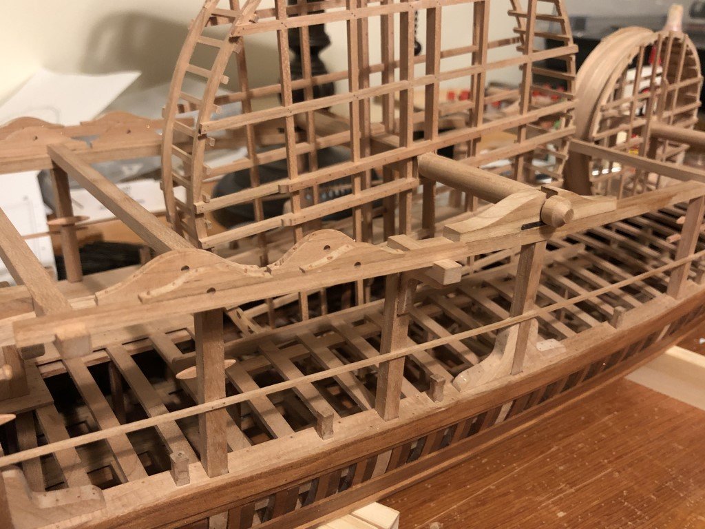
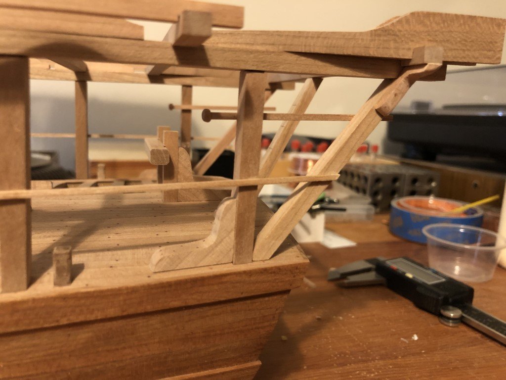
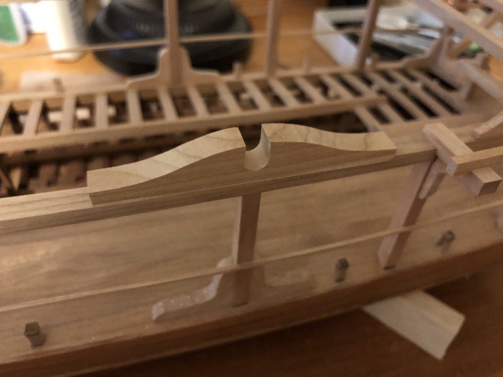
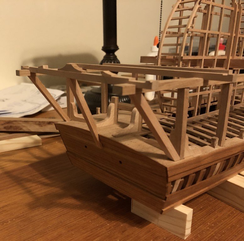
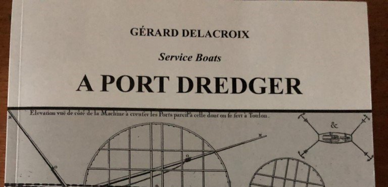
This evening I finished adding the three slanted pillars at the rear. Then I had time to make and install the mooring cleats that affix to the last superstructure cross-bar. If I understand the monograph correctly, one way the dredger can be held in place during dredging operations is through the use of four anchors. Two in the front and two in back. The front two would have their anchor cables bound to the fore bit as expected; the anchors being set at angles radiating away from the vessel. Much like the small illustration on the cover of the monograph. The aft two anchors also would have their cables connected to the bitts; however, they would not radiate like in the illustration as they would then foul the operation of the scoops. Instead the cables would go up and over the last cross-bar (between the cleats) and would then drop down into the water in such away that they would not foul the dredging process. The mid slanted pillar helps support the added strain from this method of mooring the vessel. Later, steps will be added to this pillar - a means for crew members to manage the mooring lines.
-
The mill is the model 5400 12" manual mill made by Sherline. I bought it (and one of their lathes) in 2012 and have not had many issues over the years. I have used the mill much more than the lathe. In hindsight, being enamored with Ancre publications, I now wish that I would have purchased the machines having metric scales instead of inches. I spend a good deal of time doing unit conversions! About 4 years ago, I committed a huge power tool no-no with the mill. My eyesight is not great, so when I use the mill I typically take my glasses off to better see what I am doing. My hair was long at the time and I did not have it tied back / contained at all when I was working and yes, my hair got caught in the belt drive. I was so lucky that this is a hobby mill instead of a larger mill. Even so, the Sherline had plenty of power to pull me to the machine before I could flip off the switch. In this very short time period a good size chunk of hair was pulled out at the roots. It was a dumb move on my part as I am well aware of the hazards and try my best to maintain a high level of safety; but this one time I had rushed, didn't think, and clearly payed the price.
-
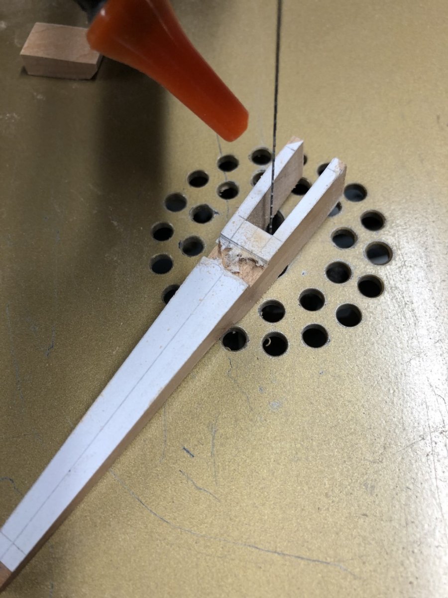
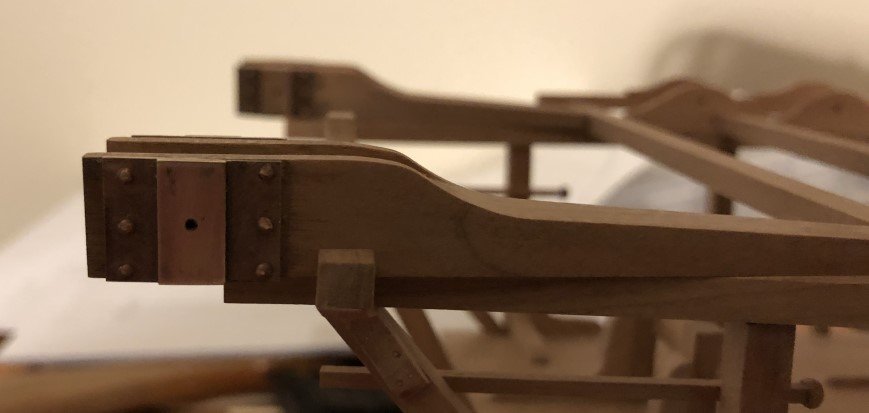
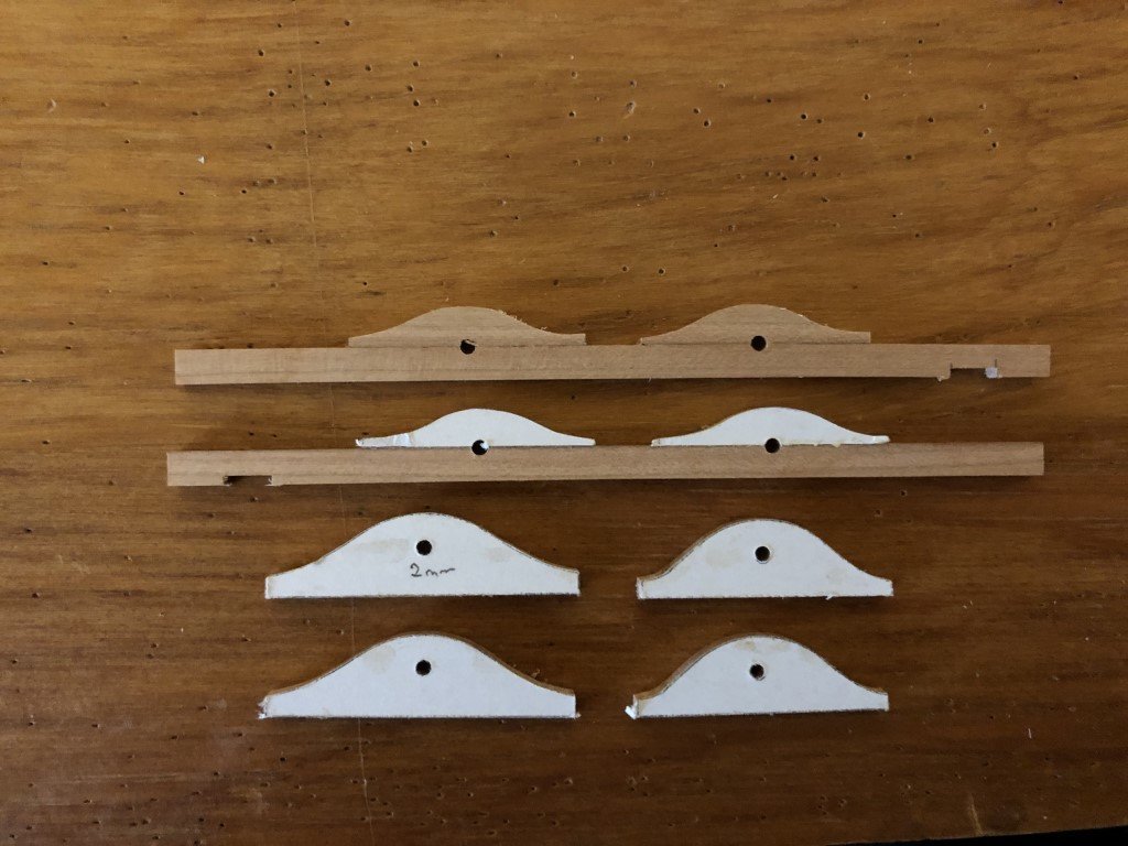
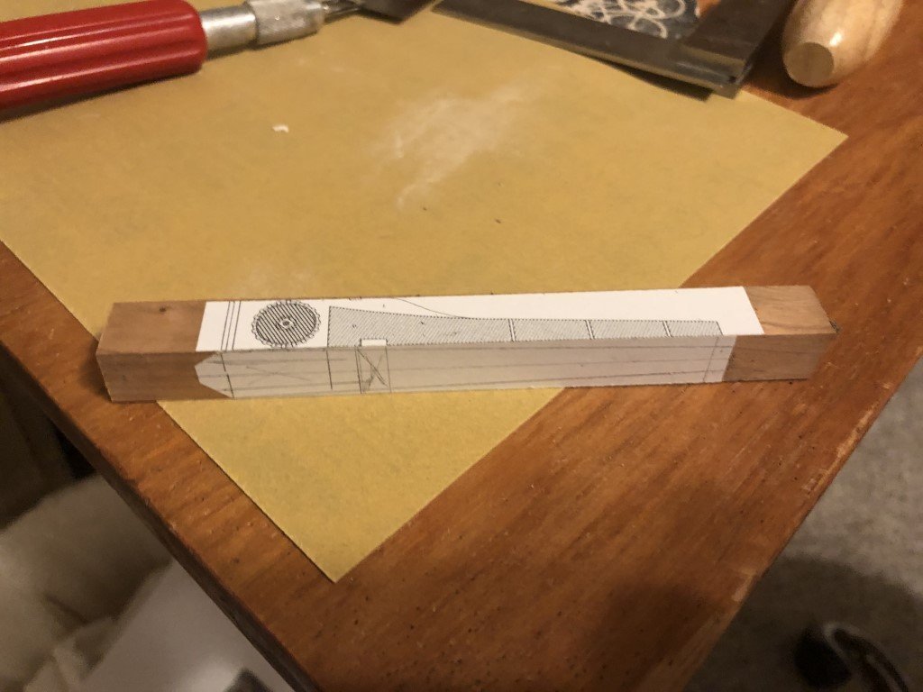
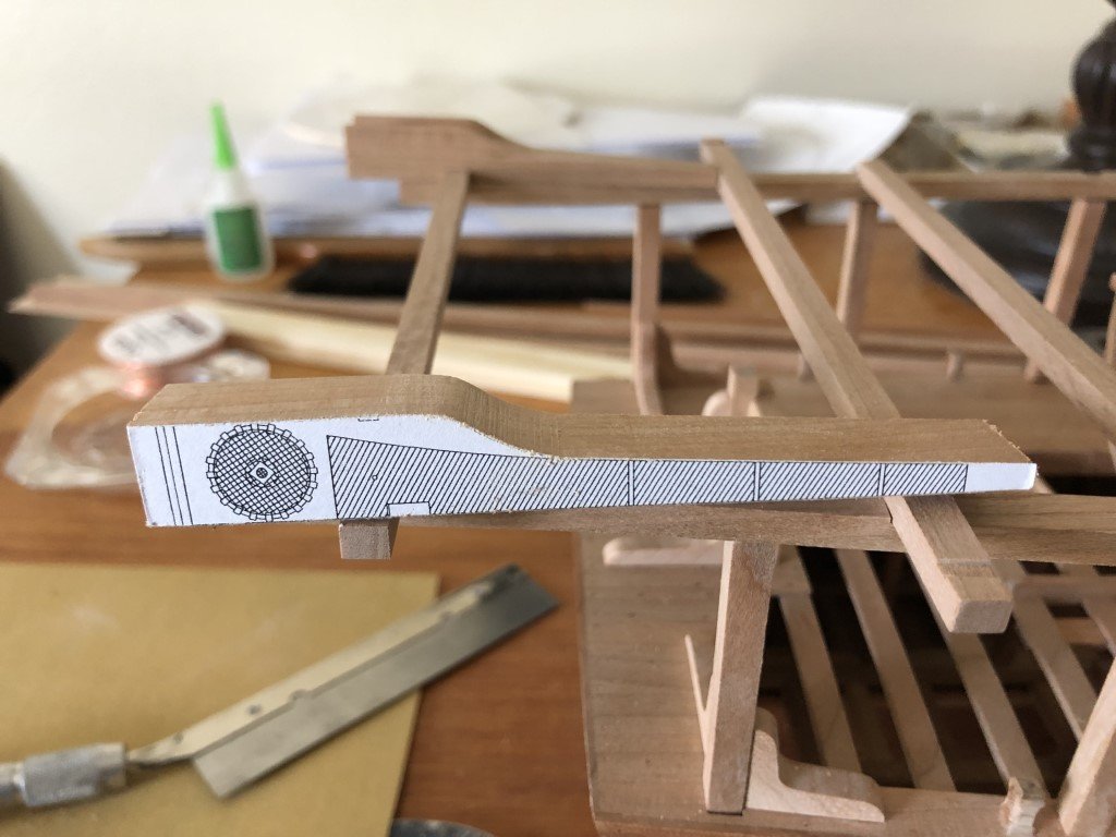
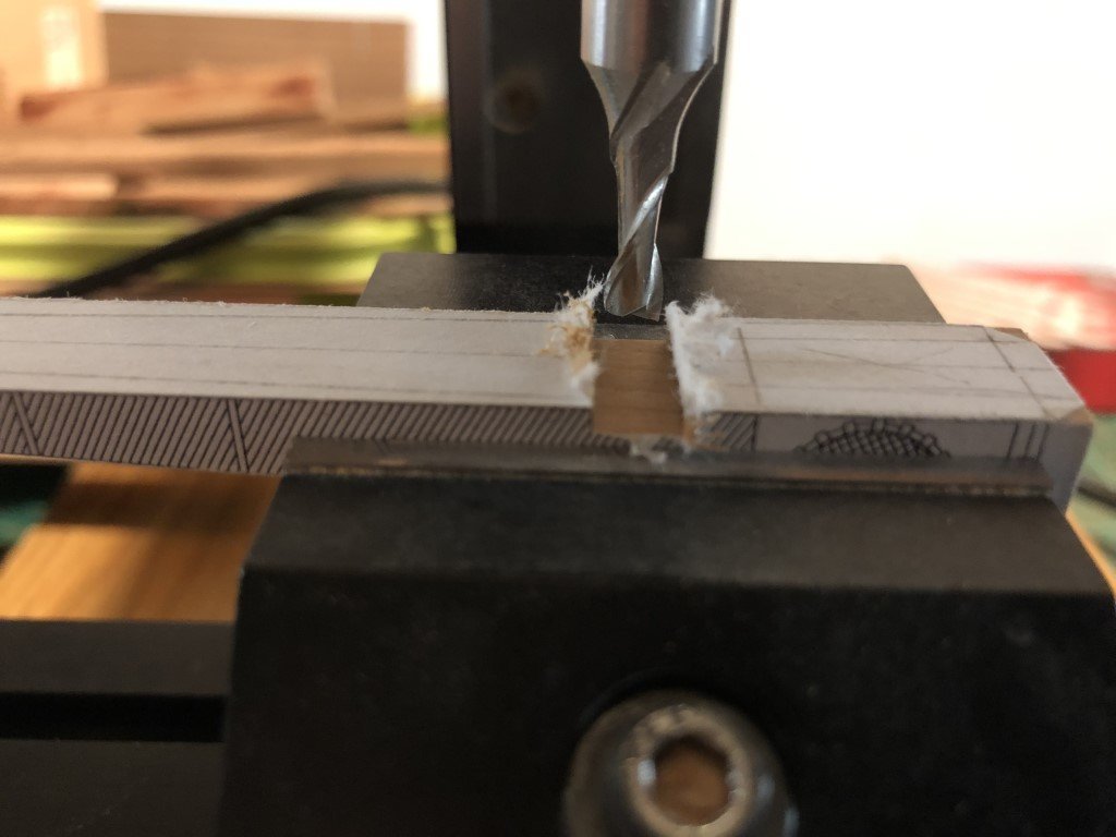
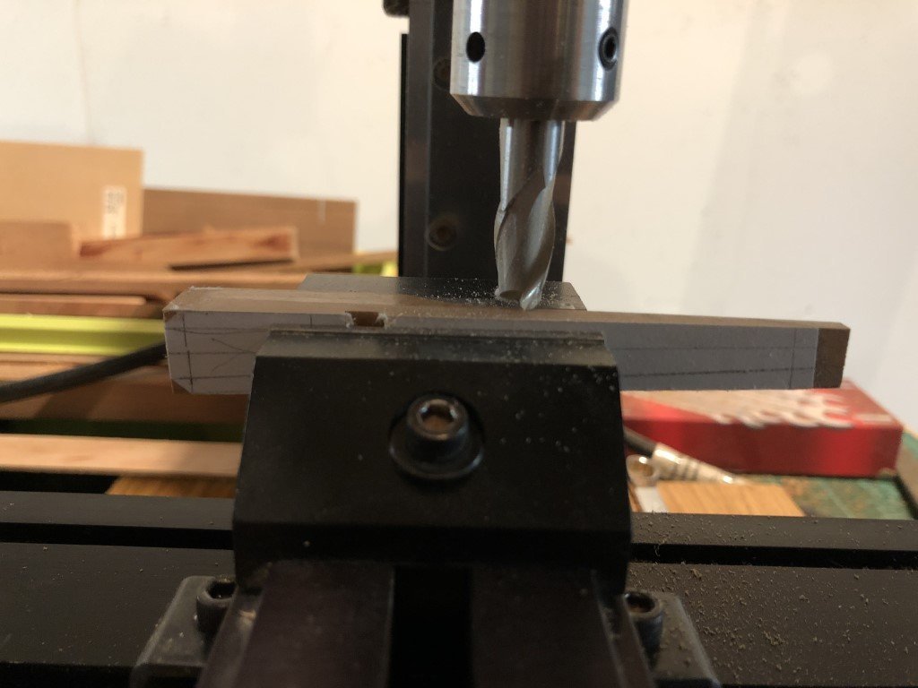
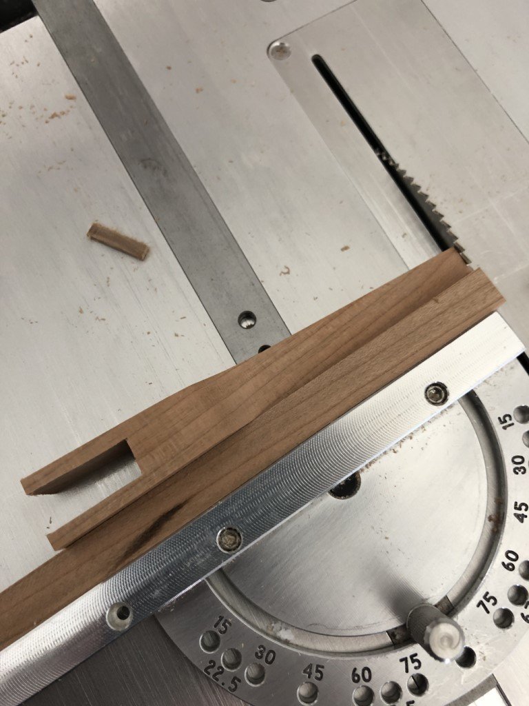
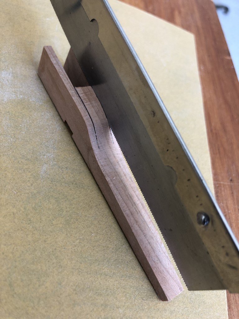
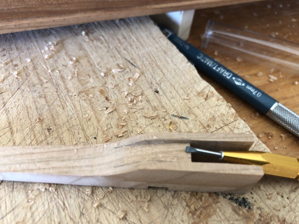
I wanted to share how I decided to make the davits. First of all, according to the monograph, the davits can be constructed in two different ways. One way is to make each davit out of a single piece of wood; the second is to make it out of three pieces - one central piece and two sides. The model presented in the monograph has davits built in three pieces; whereas I've seen the davits made in one piece presented in online build logs. I chose to make each davit out of one piece of wood. After I made this choice, I formulated several orders of operations in which to fabricate them. This is what I finally settled on. I don't know if it is the most efficient way to do the job, but it did seem to work well for me. The first attempt was a fail, but then I got the two I needed on the next tries. I started by rubber cementing profiles of the davit to a length of wood 13.3 mm square in cross section. Note the center axis of the top/bottom profile is centered on the blank. I then milled the top profile. Having the top/bottom profile centered let me mill this portion perpendicular to the blank. Here I have started to smooth the curved region, but you can still see the horizontal lines left as steps from each pass of the milling process. Next the bottom slot, where the davit locks on the superstructure was milled - note this is at an angle and there are specific left and right davits. I then milled the two sides, the last milling operation. Using a scroll saw, the front space was opened up, after which the front length was shortened and then finished on a disk sander. The back length was then adjusted so the davit fit correctly on the supperstucture. Now it was time to remove some material in the middle to provide passage for the scoop chains. First I marked and sawed boundaries for the region to be removed. The unnecessary material was mostly removed with a small chisel. And the final shape of this inner region was developed using a sanding stick.

- 199 replies
-
- 16
-
-
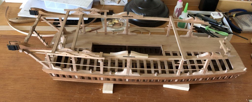
Since last post, I have been skipping around a bit and getting various tasks completed and/or worked on. I also got to take one of my grandsons down to the Wisconsin Maritime Museum yesterday. While the WWII submarine Cobia was the main reason he wanted to go, he does seem to be getting more and more interested and knowledgeable about the model ships displayed there - I harbor a hope that one day we build a ship together! The museum is in Manitowoc, Wisconsin - a city of about 30,000 and with a strong heritage of ship building. All of the steps are in the big wheel and I am preparing (bending) planking material for that wheel now. The two big davits are shaped and ready for some metal work. All the bollards have gotten their final shaping. The 12 knees that support the pillars at deck level are finished and installed along with the appropriate fasteners. Similarly the two sets of bits and knees are permanently connected to the vessel. The last thing I did today was to cement the superstructure unit to the pillars. The davits are just sitting on the structure for the pic.
- 199 replies
-
- 10
-
-
-
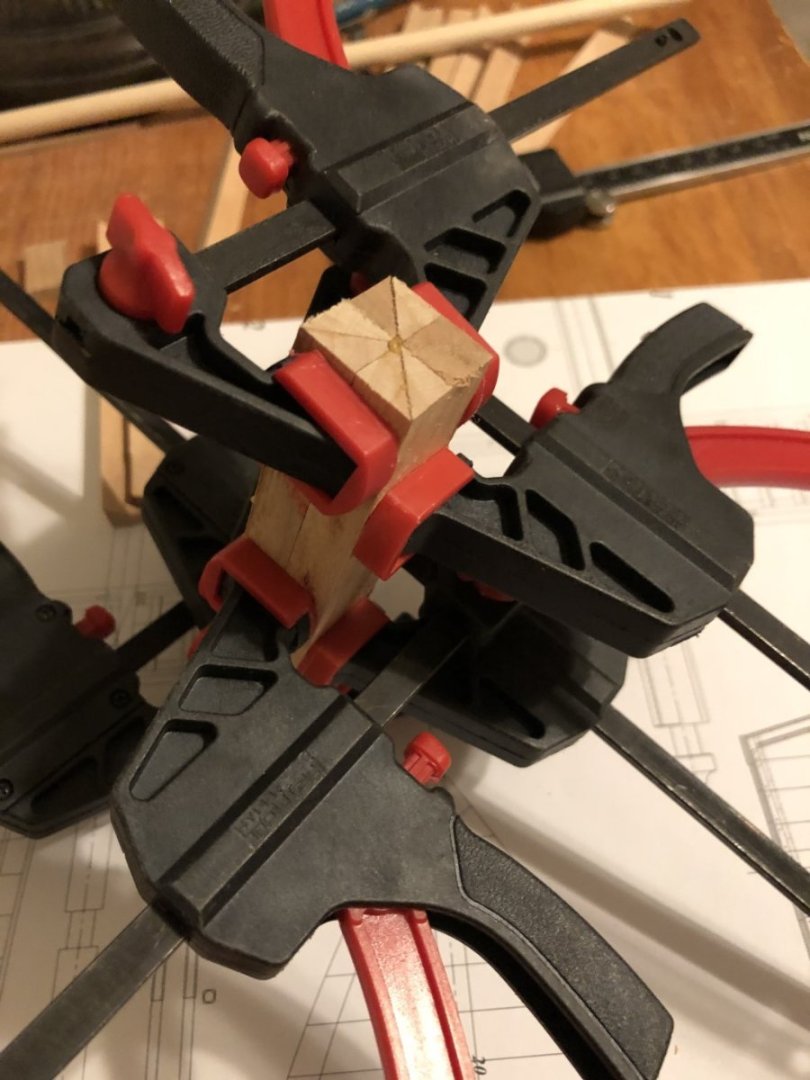
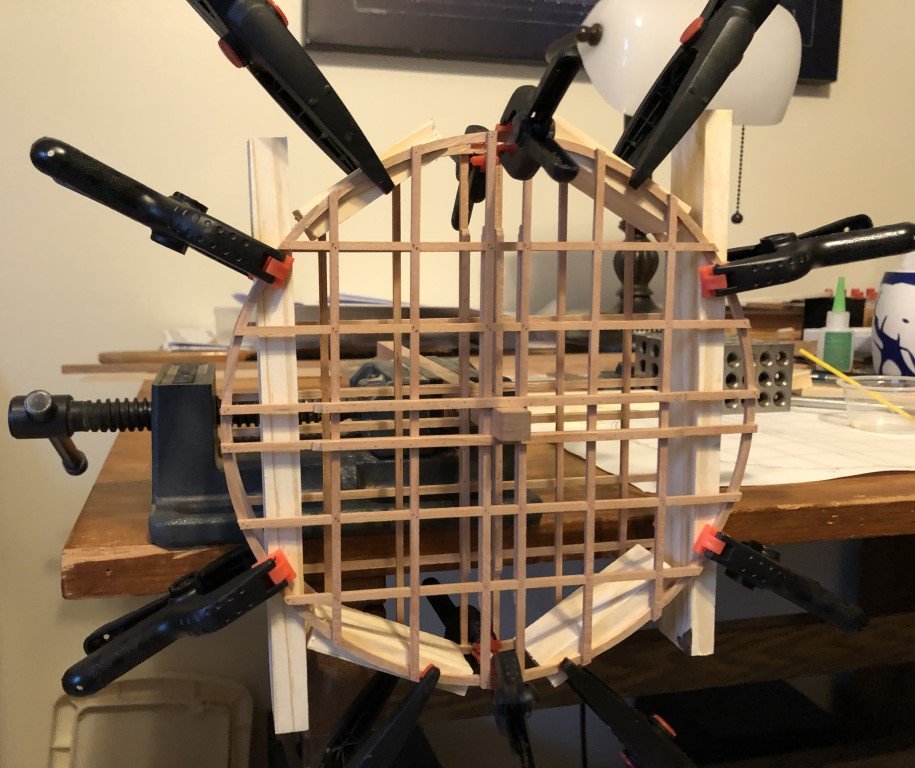
All the fasteners for the big wheel timbers have been added. I've lined up and clamped the two rim structures with 18 mm spacers between the rims. The first couple of steps have been attached - there are 60 steps needed in this wheel, nearly twice as many as in the small wheel.
-
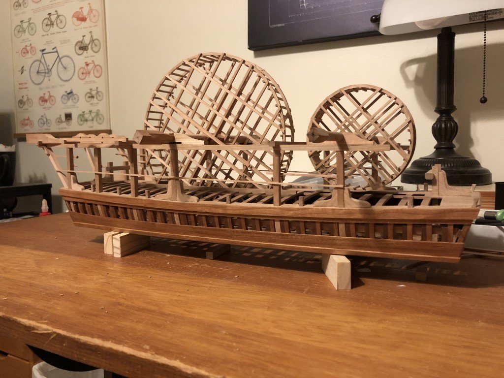
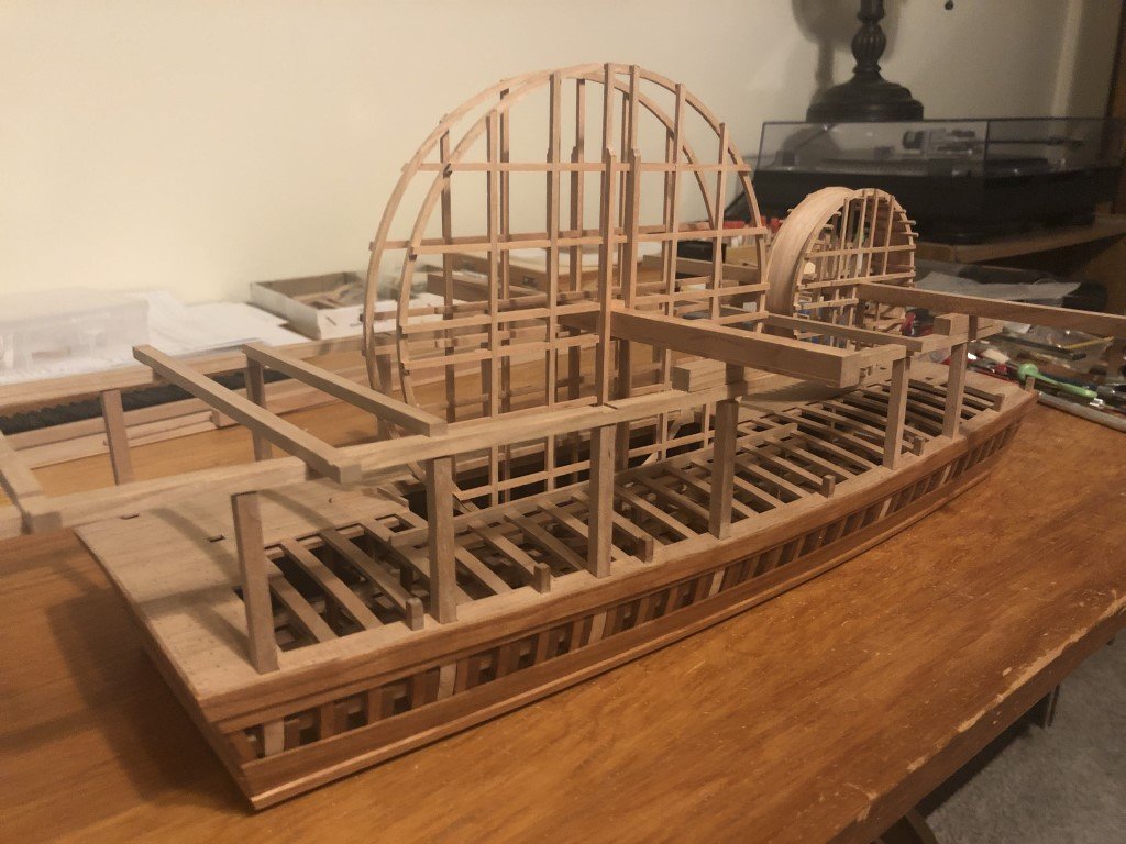
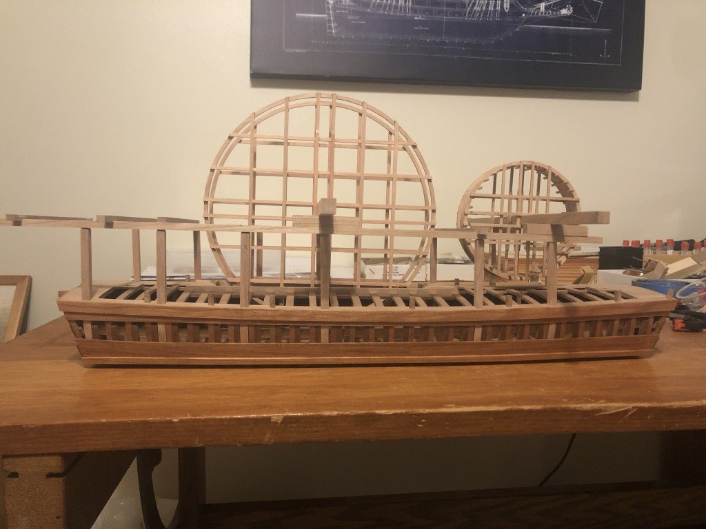
Today I made it to having the big wheel timbers installed. After doing so, I couldn't help but 'mock-up' the vessels configuration with the wheels! You can see in the second picture that I have completed planking the small wheel. The small wheel will now get about 200 fasteners thru the planking and steps. Then the excess material on the steps will be trimmed and it shall be done. Repeat for big wheel coming as well,
- 199 replies
-
- 18
-
-
-
All of the foot steps are in the small wheel now. I have gotten the first piece of planking formed and it is now being attached to the wheel. Here you can also see my progress on the big wheel - one rim done. I've still to mill the joints for the other big wheel rim. Quite a difference in diameters between the wheels!
- 199 replies
-
- 10
-
-
-
Thank you all - although I'm not too sure about the 'innovative' part. I read a lot and think a bit to pick what I believe will be a reasonable way to proceed. I know that I have a great deal to learn about the model building process, let alone try out in practice. It is my guess that most everything I come up with has been done before. There have been, and currently are, so many involved in this hobby that it is only natural that multiple people we arrive at / discover common solutions to similar problems.
-
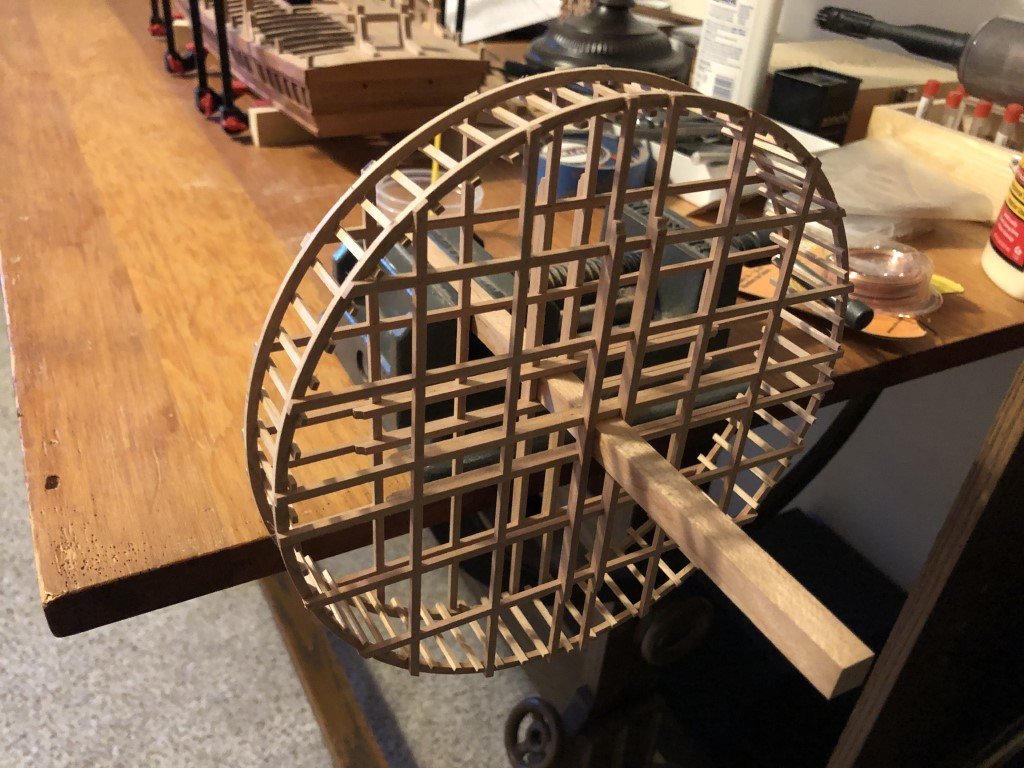
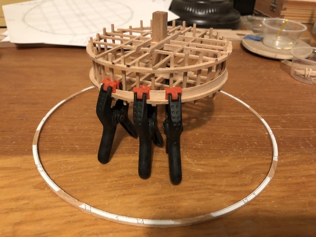
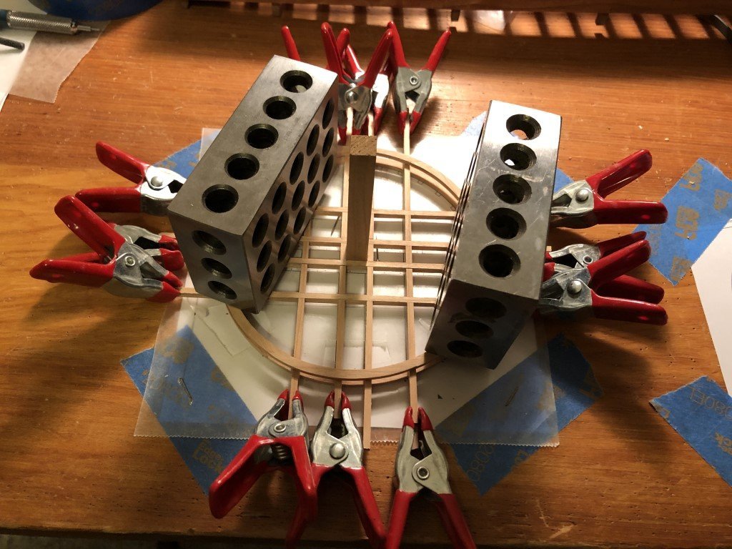
Some more progress on the wheels today. Here is the status of the small wheel. It now has 75% of its steps, the remaining 8 will probably be added tomorrow. They are the ones that need to be cut to exact length before attaching because they fit inside of the outermost timbers. The other steps currently extend beyond the rims and will be trimmed after the wheel is planked. The disk under the cup of steps is not a drink coaster (yet). It is a disk cut to the diameter of the wheel where the planks will be fitted and is being used to induce the proper curvature on the plank material. Here a strip of wetted plank material has been wrapped around the disk and is being held in place with a rubber band as it dries overnight. The 6mm wide planking is just 0.55mm thick and bends easily; however, I want to minimize any strain on the steps as they are fairly delicate. As far as the big wheel, the rim segments are ready to have their scarf joints milled. I also have made a disk for forming the big wheel planks.
- 199 replies
-
- 11
-
-
The the doublers and fasteners are in; I made the fasteners using 26 gauge copper wire in #77 drill holes. I'm glad to have had the practice with the stiffer 24 gauge copper before having done this work. The 26 gauge wire must be fed precisely into the drill holes or it will easily bend. Step locations have been marked on the inside of each rim. It shouldn't be long before they are attached. I'm starting to go back and forth between the two wheels and started to form the rim components for the big wheel today.
- 199 replies
-
- 13
-
-
-
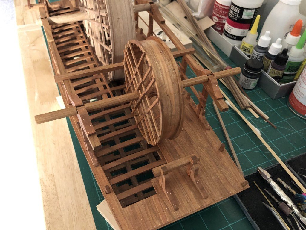
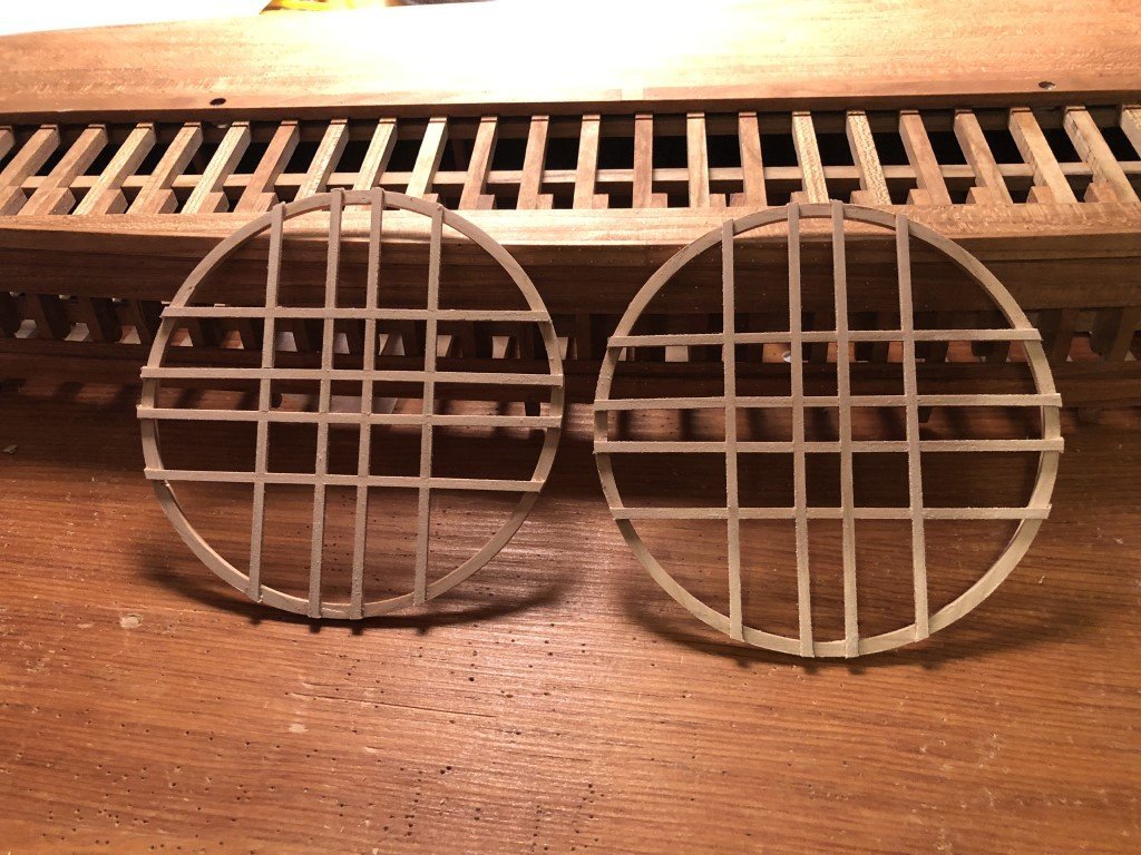
Over the weekend I milled the scarf joints for the rims and assembled them. Next having the wheel timbers milled and connected, they were fastened to the rims - one on top the other so to have well matched pair. Here are a couple of pictures; the first picture taken when the timbers were being attached to the second rim, and the second picture after the timbers had been sanded to the rim's outer contour. There are four timbers still needed for each of these sub-assemblies, they will be doubling the timbers that surround the region that the axel passes thru. After that is done, there is another opportunity to add copper fasteners before the two assemblies are connected via the steps.
- 199 replies
-
- 12
-
-
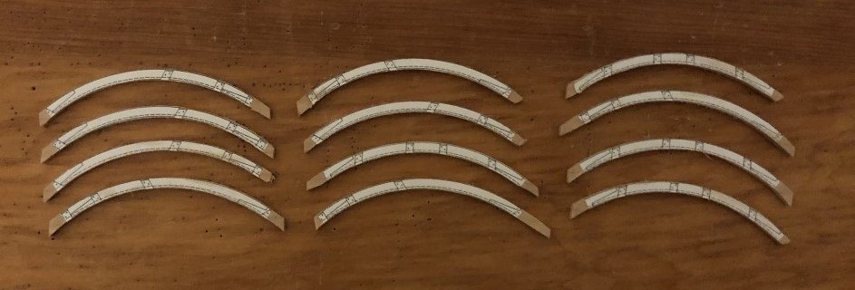
Working on the wheels was the winner. Yesterday I milled wood for the wheels - three 3" x 24" sheets with thickness one each of 2.25mm, 1.5mm, and 0.55mm. This should be more than enough for all of the parts plus a few missteps. Today I was able to start forming the 12 pieces needed for the rims of the small wheel: Now they need to have scarf joints made to join together. This is certainly more tedious than building bicycle wheels. Back in the day when I raced regularly, I laced and trued my own wheels. No more racing now, and technology has changed so much that almost all my current bike wheels are factory made. Still follow professional racing closely - VPN software is amazing for picking up live feeds all over the world! But got a bit more modeling minutes today when today's stage of Paris-Nice got cancelled due to high winds.
-
Awesome! Certainly deserves to be finished and displayed! Thanks for sharing, Greg
-
Had a bit more time to work on this project today, so I oiled the hull. Instructions on the can indicate that the oil should be dry in 16-24 hours; however, I'll give it a few days to get really dry before flipping her over and doing anything to the deck. In the meantime, there are many fittings to be made for the superstructure and/or some time could be spent on the wheels ...
- 199 replies
-
- 10
-
-