


cdrusn89
-
Posts
1,598 -
Joined
-
Last visited
Content Type
Profiles
Forums
Gallery
Events
Posts posted by cdrusn89
-
-
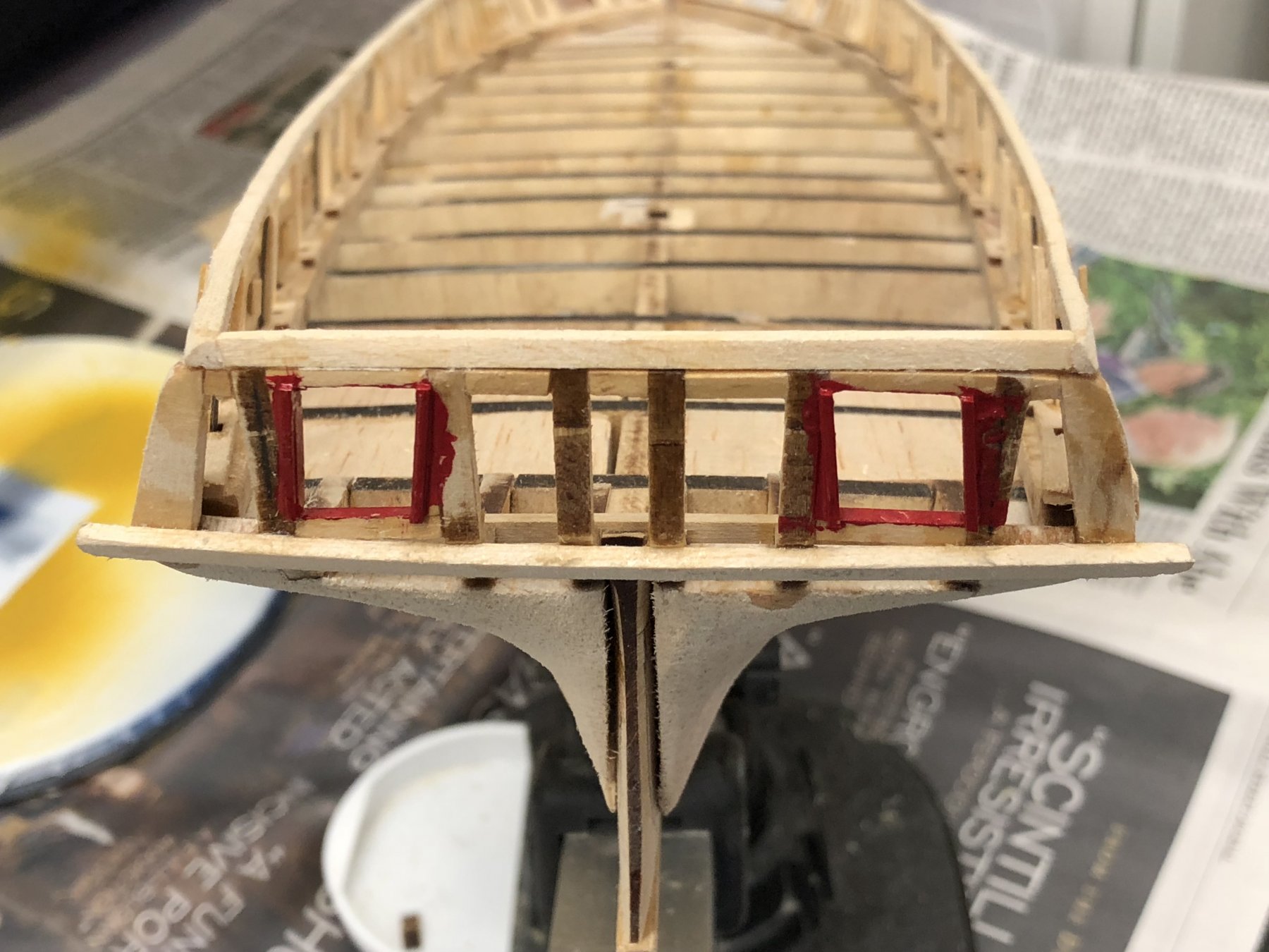
When I looked at the stern I decided to plank it "in place" and paint by hand. Sooo I had to apply the first paint to the ship - the red framing pieces around the stern gun ports. So here she is ....
Sorry about the lighting - may have to invest in some flood lights by the paint booth.

-
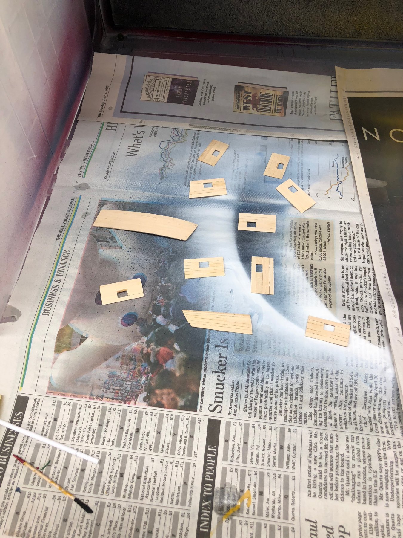
After what seems like a long time I finally have the bulwark planking sections completed. Here are the port and starboard pieces awaiting priming and painting before being installed (actually the stbd forward most piece is drying on the hull after being soaked and clamped in position). I also need to paint the wales (I have both pieces of 3/64s material installed) black (by hand) before installing any of the bulwark planking. But before any of that I am going to plank the ceiling and stern. Probably easier without the bulwark getting in the way and another opportunity to mess up something that was previously "done".
-
Darrell,
I got a Paasche VL and several spare needles and nozzles. All I need now is practice, practice, practice.
-
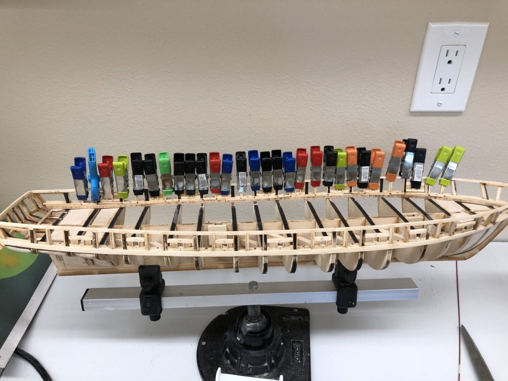
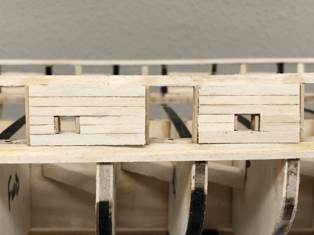
While waiting for the glue to dry on the upper and lower wales on the port side I added the 3/64" square port framing on the interior of the port side. By the time both sides are done inside and out I should be pretty good at gluing really small pieces to the bulwarks. Airbrush was delivered today and I am "messing around" trying to get the feel for how close to get and how much paint/air to use. Am going to have to come up with some way to hold the smaller parts (like the sections of bulwark planking) to keep them from blowing around while being painted - maybe double sided tape. Here are the port side interior framing under the clamps.
-
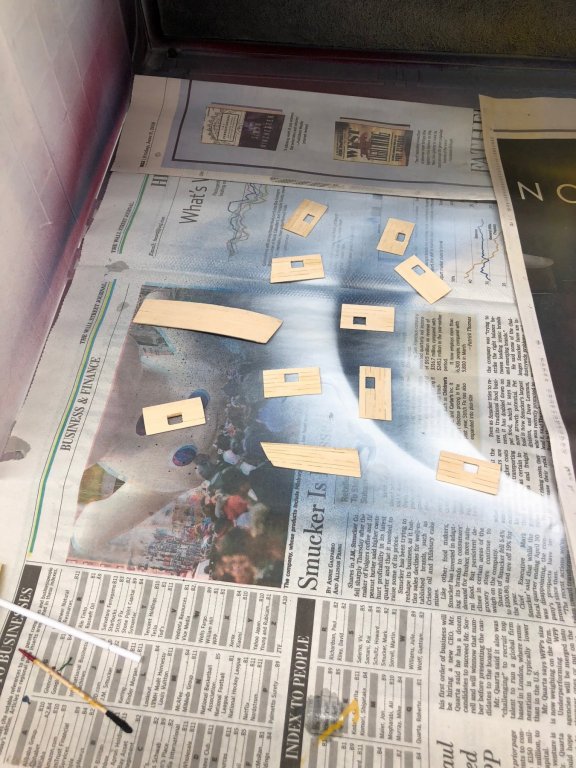
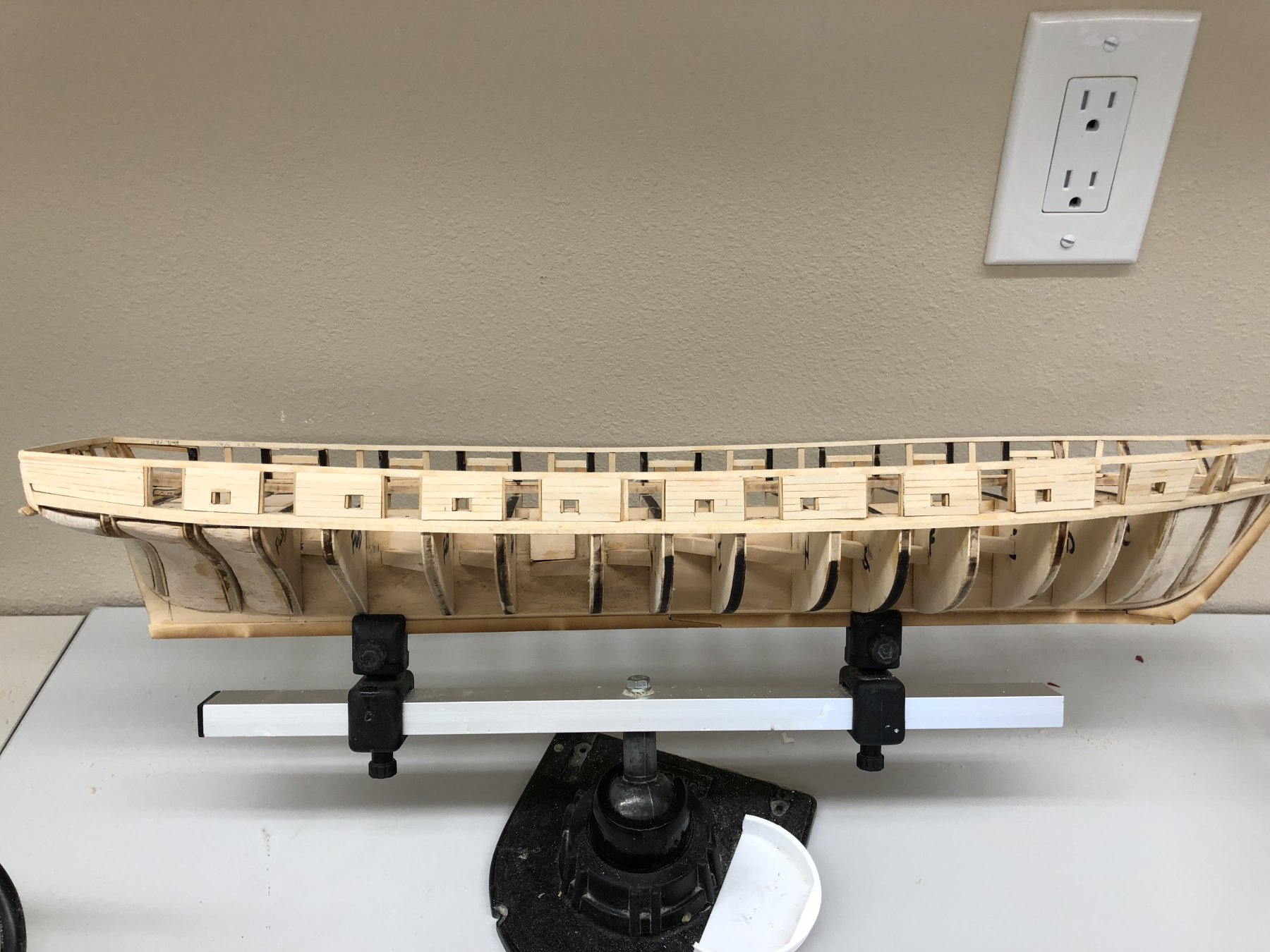
I completed fabrication of the bulwark planking (outside) for the starboard side except the more complex portion forward of the forward gun port. I am considering using a "carrier sheet" of 1/64" plywood to hold the planking as was done by Ken (aka XKen) in his build log. I have not done this before but DO have a supply of 1/64" plywood (which by the way is not cheap) on hand in anticipation of this eventuality. Anyway here is what the "easy" part looks like on the starboard side. I still have to add the port framing on the port side and fabricate the bulwark planking for that side and then tackle the inside. The panels are just setting in the proper places here. Nothing gets glued in until the bulwark and framing have been painted.
- Jim Rogers, Tom E, JpR62 and 1 other
-
 4
4
-
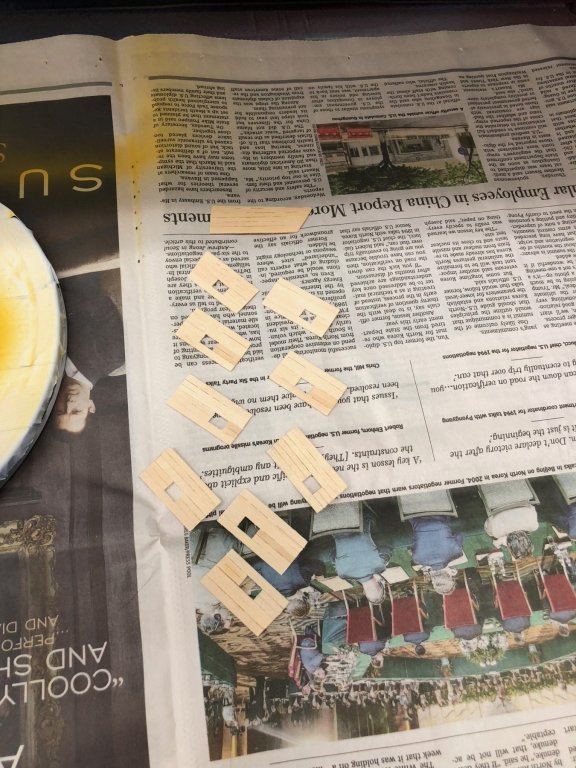
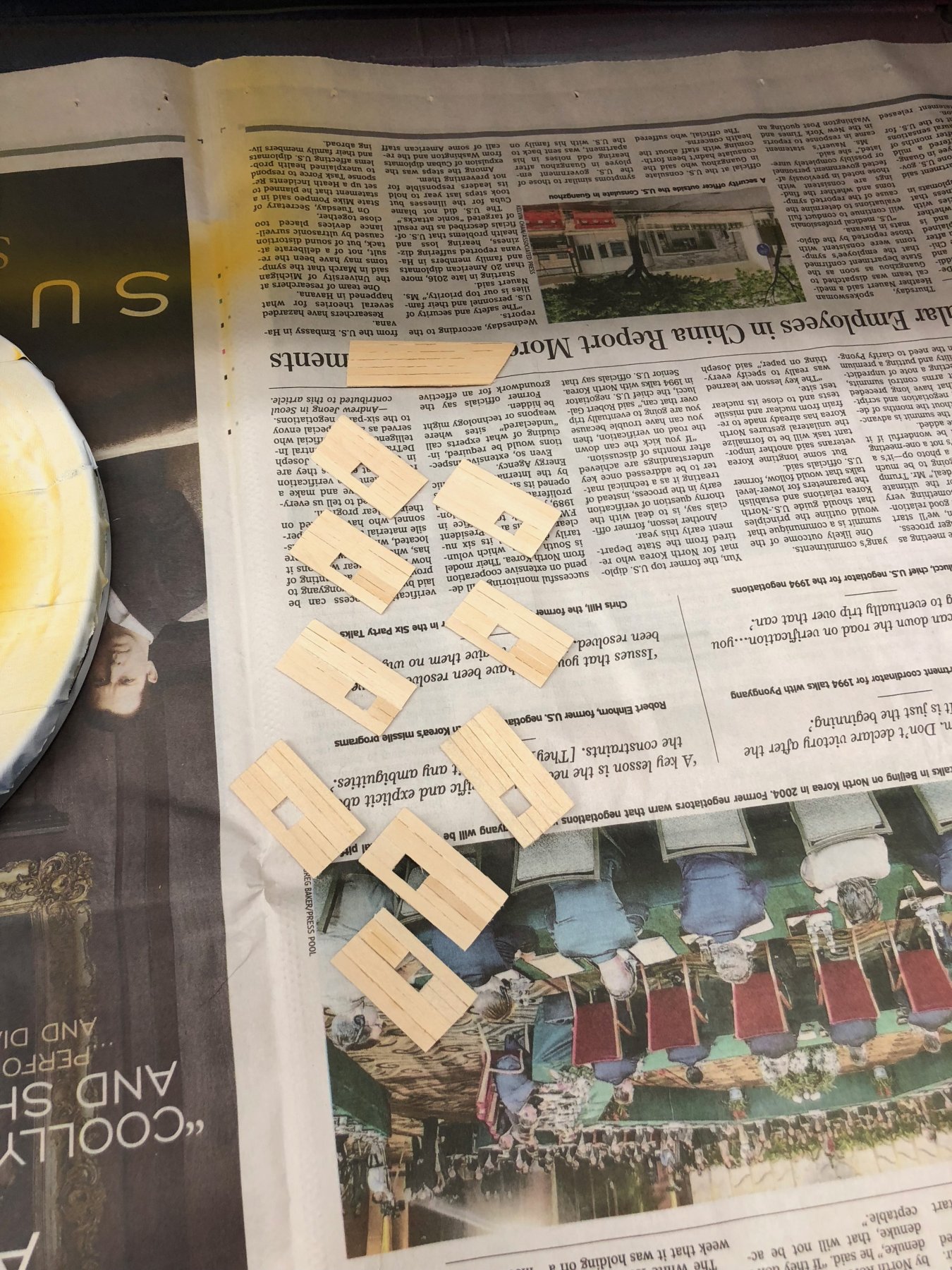
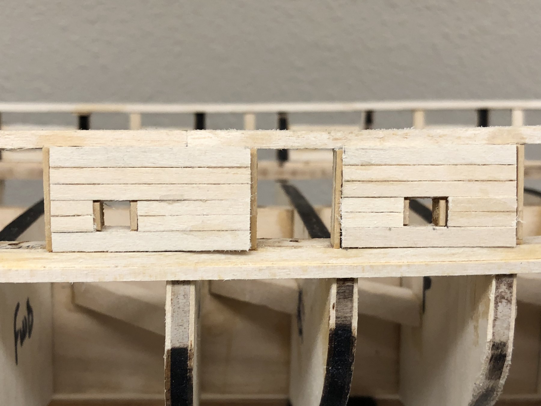
I completed all the framing on the starboard side and decided to see what the best way of planking the outer bulwarks would be. Given that the framing around the ports is supposed to be red and the outer bulwarks are yellow I was trying to avoid having to paint the thin frames or paint the bulwarks without getting paint on the red frame. As was done on a previous build log, one solution is to build the bulwark planking in sections that are painted before they are mounted on the hull. That way the framing can be painted before the bulwarks are planked and (in theory) the painted bulwarks mounted and everyone lives happily ever after. Since my new airbrush comes tomorrow and I spent last weekend going to "Airbrush 101" I thought this would be a opportunity to try my hand at using a airbrush to paint the bulwarks before they are mounted. So I started building the bulwark planking "modules". Below are the first three. Hopefully I will get better as I go along.

-
Similarly for the sweep port framing although I did not use any CA on these and tried to keep the glue only where the frame would remain after trimming.
- Dwight, Tom E and GrantGoodale
-
3
-
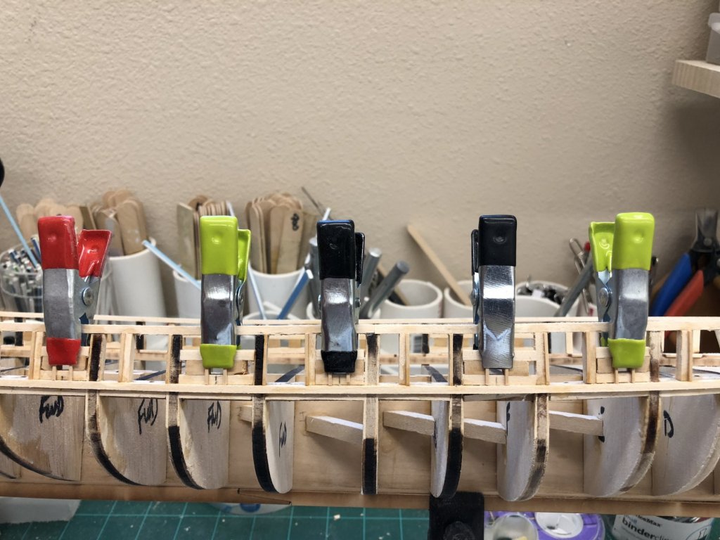
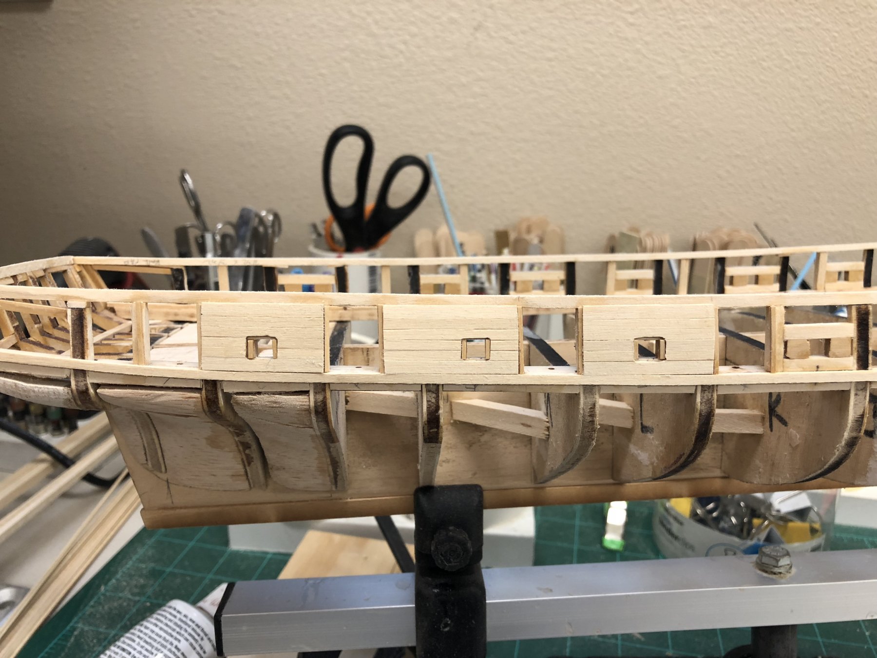
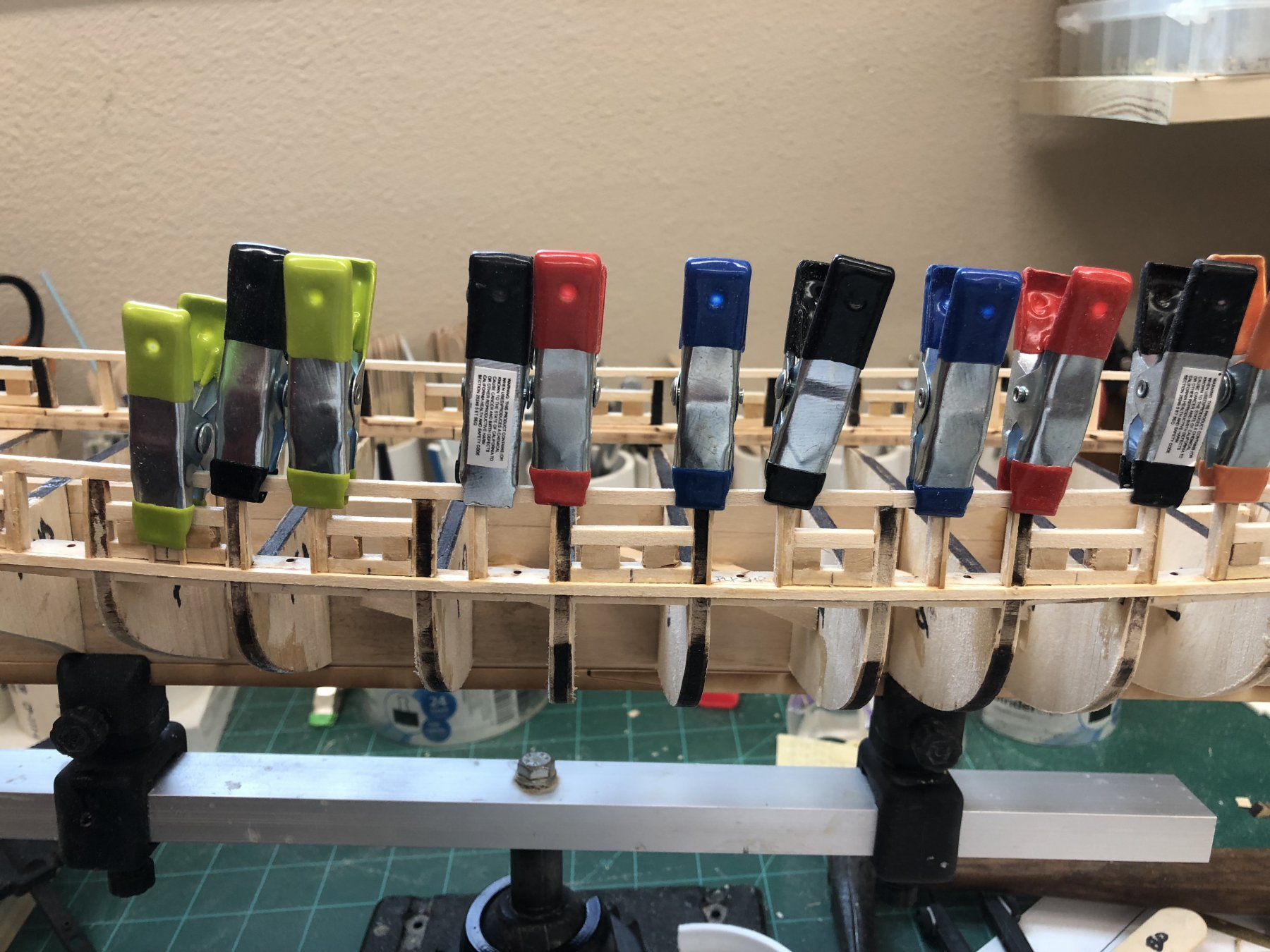
I found the 1/32 X 1/32 material supplied with the kit was "dimensionally challenged" so I decided to use some boxwood I had of the same size. I did the gun ports first, using wood glue along the support or stanchion and a drop of thin CA at the bottom where the gun port frame meets the upper wale. I cut the pieces long and then trimmed to the top of the port using a new Xacto chisel blade. I used the wide blade so I could get both sides of the port at one time. Hopefully this will reduce the chance of cutting them to different lengths. Picture below shows the gun port framing clamped in place while the wood glue sets. As has been said before in this forum "you can never have too many clamps".

- Tom E, GrantGoodale and Dwight
-
3
-
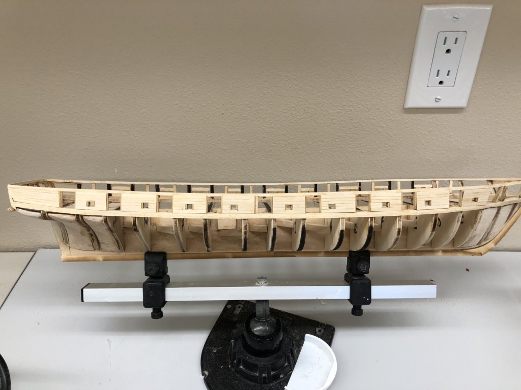
Sanded down the starboard side and installed the 3/64 X 3/32 "upper wale". Having previously filled in the gap between the laser cut planksheer and the outer mold line paid off here as there were no additional gaps encountered. Will work on the 1/32 X 1/32 filler pieces around the ports now.
-
-
Ric - are you going to plank over the sheet wood? I got all the sweeps and gun ports done on the stbd side and hope to get the port side done tomorrow and (hopefully) start planking the outer bulwarks.
-
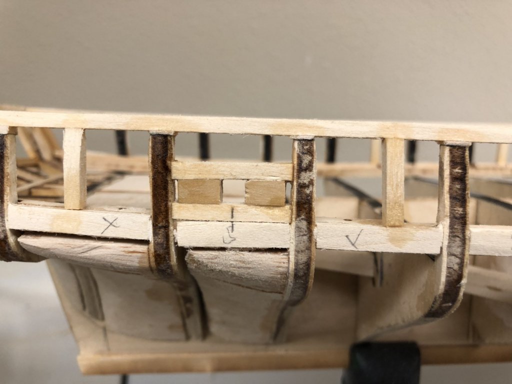
Got the gun ports framed, including the canted one for the long guns forward. Started on the sweep ports but trying to cut pieces of 1/8 X 1/8 (or 3/32 X 3/32) to 3/16" in length was "too hard". Try as I might I could not get them consistent enough to keep the port square. So I looked through my pile of wood and found some 3/16 X 1/8 boxwood. So now I cut the horizontal pieces overly long and cut two pieces of the 3/16 X 1/8. I use thin CA to attach one of the 3/16 X 1/8 piece between the two horizontal pieces (on a piece of parchment paper). Then use the template to properly position the other 3/16 X 1/8 piece. I carefully withdraw the template and hit the other side with the CA. Now, I measure and mark the center of the sweep opening and the center of the just created sweep port and using a disk sander incrementally adjust the horizontal pieces until they fit between the verticals. I generally try to keep the material that is in excess of the bulkhead thickness on the outside of the hull to make it easier to remove. I am guessing that getting the inside smoothed out is not going to be as easy as the outside.
- Tom E, Jim Rogers and Dwight
-
3
-
Ric - welcome aboard. I have some travel (hate to call it vacation; I am retired so every day is vacation) in August and September that will slow progress. That and the seemingly never ending "orders from Headquarters". Hope to have the hull completed before we leave in mid-August.
-
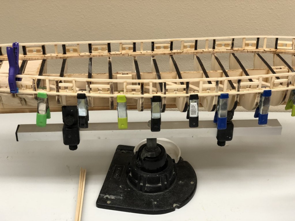
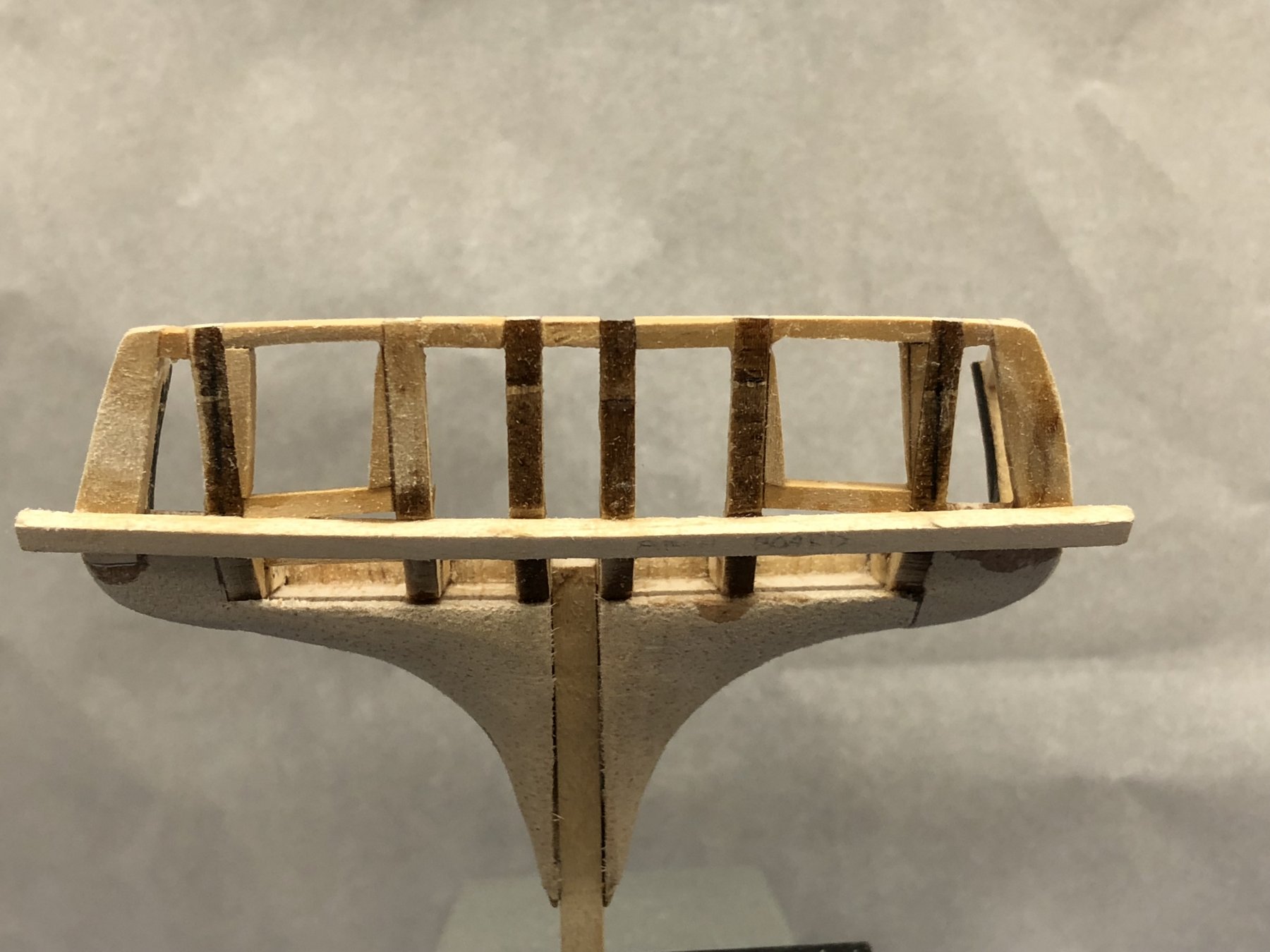
Got the 3/32 X 3/32" "sub-rail" installed around the top of the BH stanchions. It takes a decided turn upward at the stern but the build logs I have looked at all seem to have this "feature" so I did not do anything about it - like trying to taper the sub-rail where it connects to the quarter stanchions. I did use some 1/32" material (sometimes sanded down even thinner) to fill in where the BH stanchions did not meet up with the sub-rail. Hopefully I did not introduce problems that will not be evident until it is too late to fix. In the first photo below you can see both the rail fillers and the fillers added to make the planksheer even with the outer hull lines as defined by the BHs. The others show the hull with the sub-rail. It is my intention to sand all the "edge fillers" even with the BHs before adding the gun port and sweep port framing.


- Tom E and JerseyCity Frankie
-
2
-
-
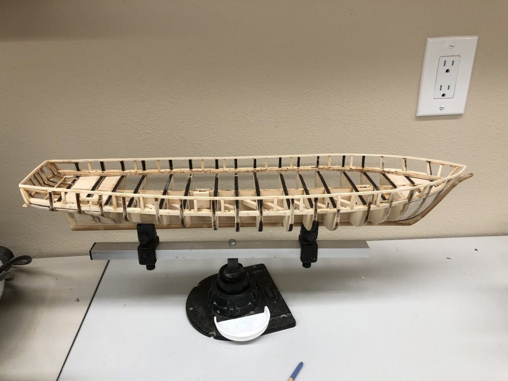
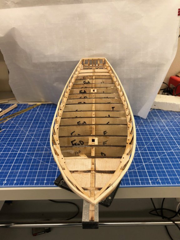
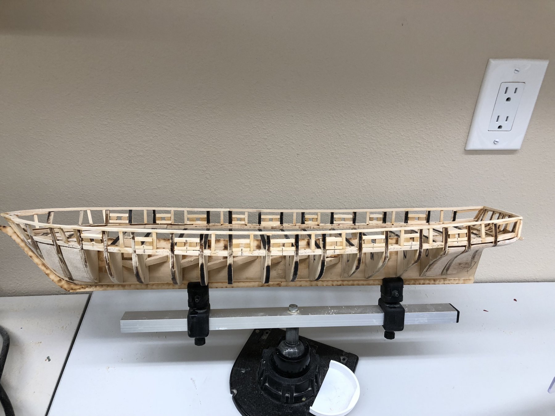
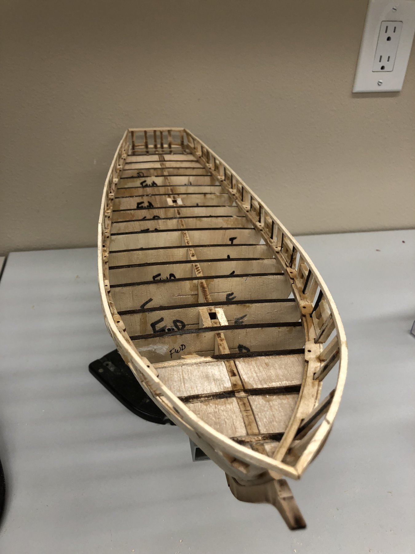
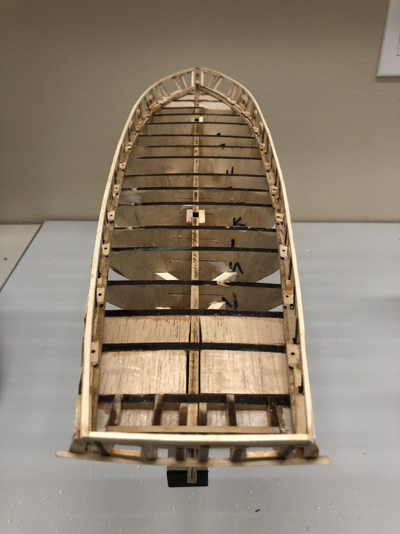
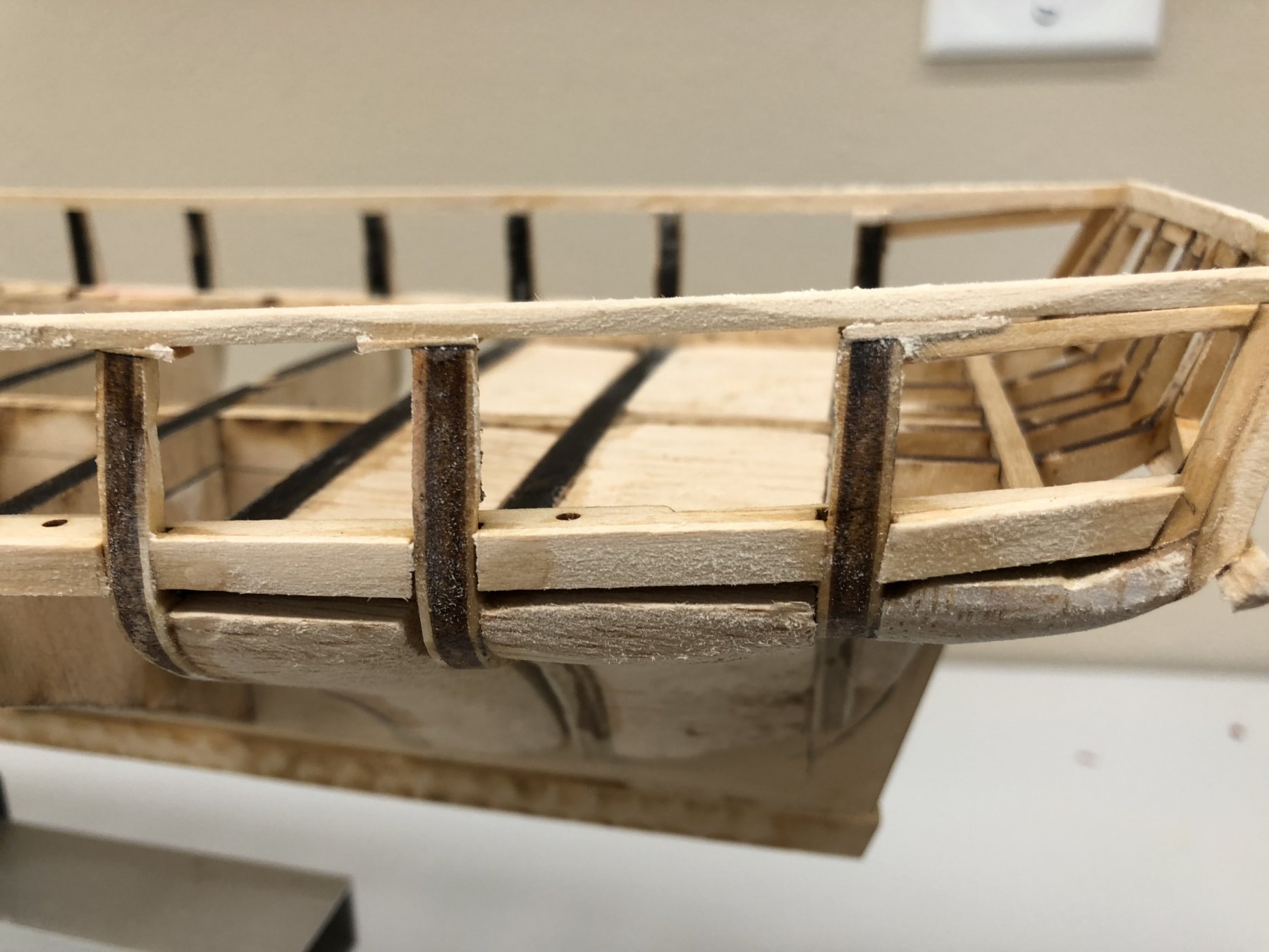
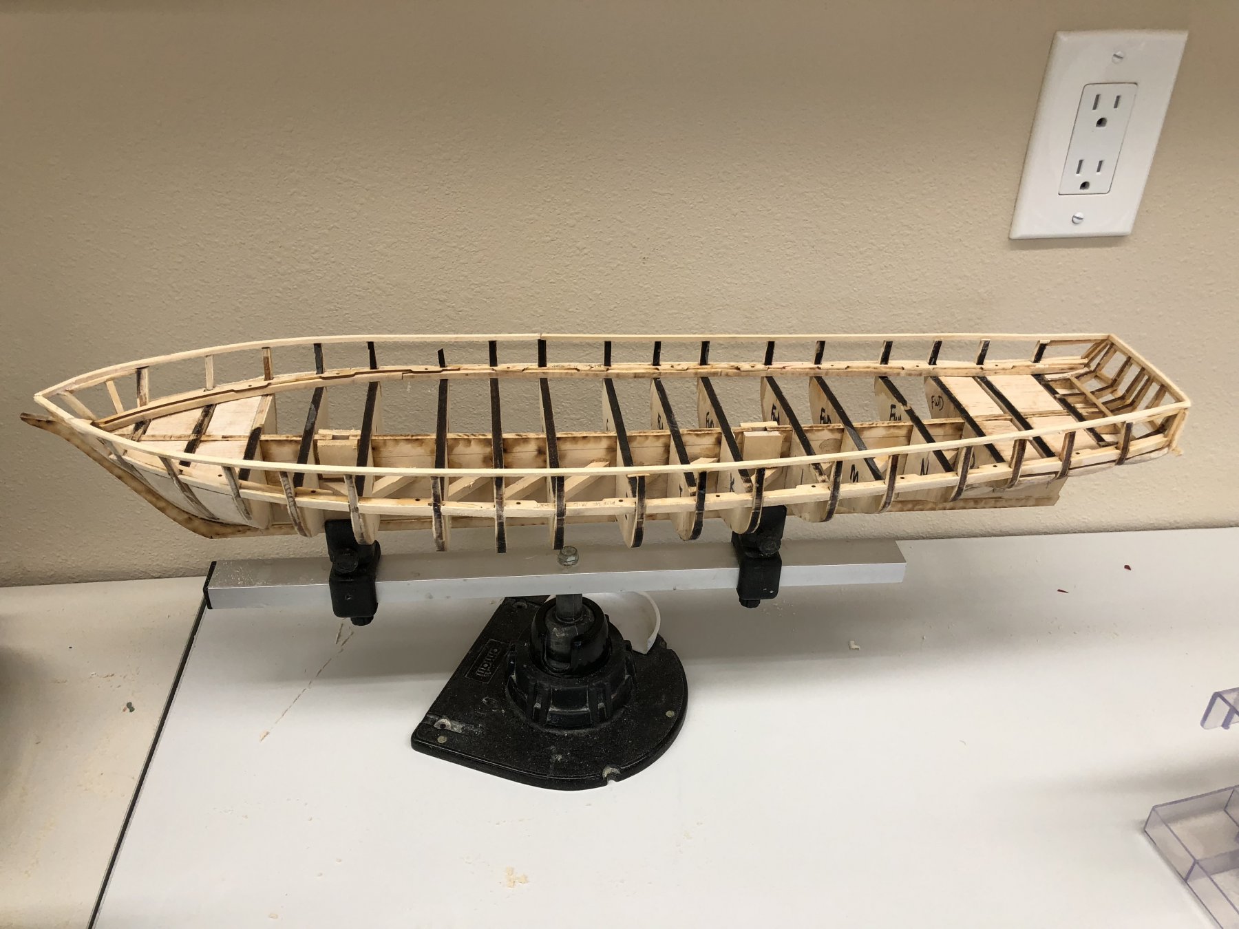
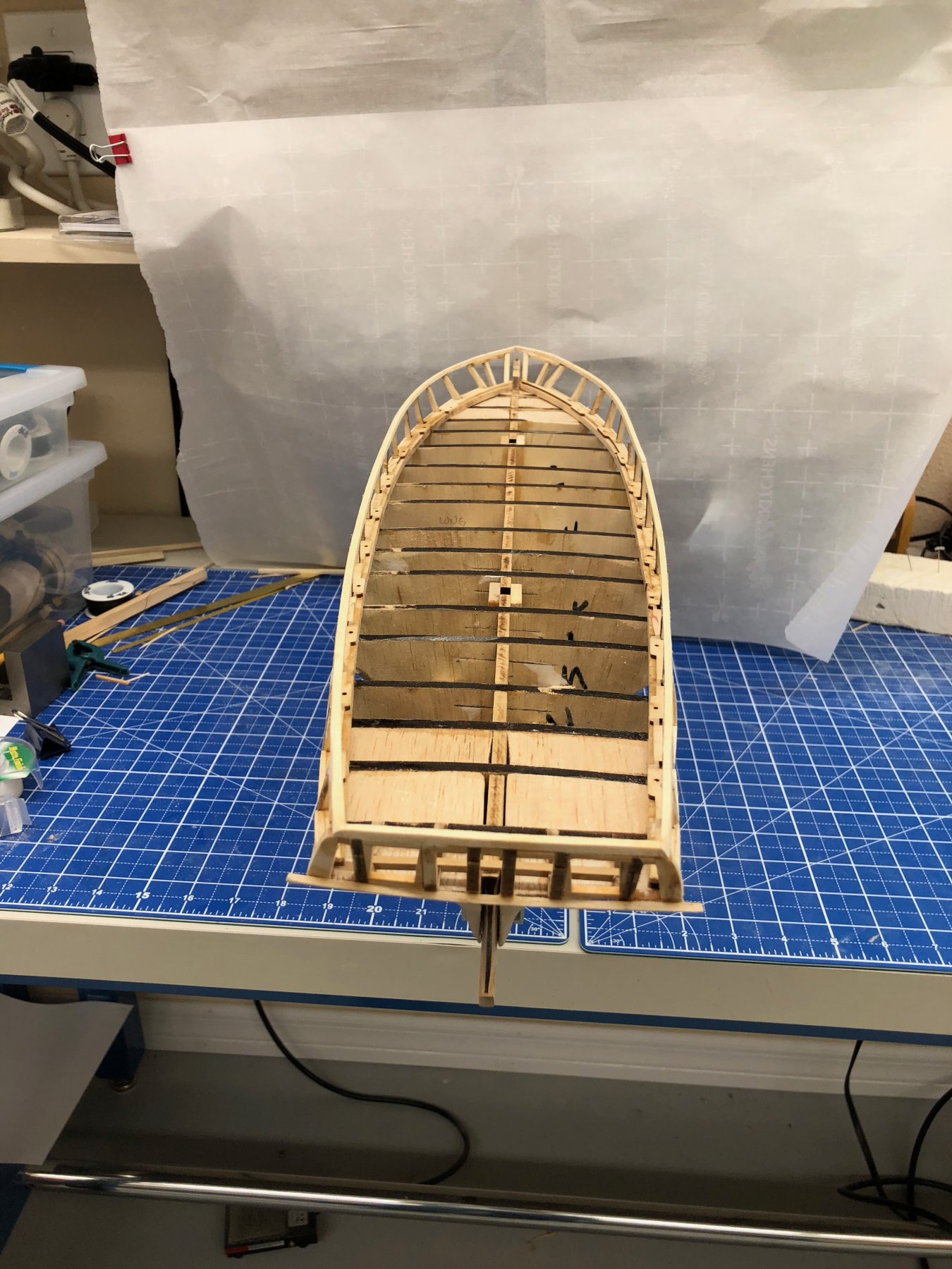
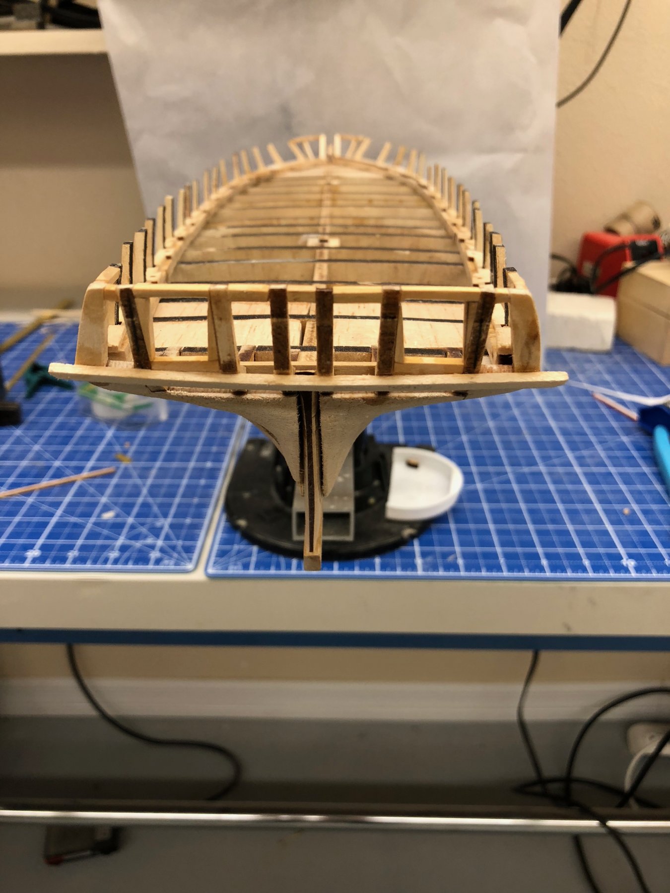
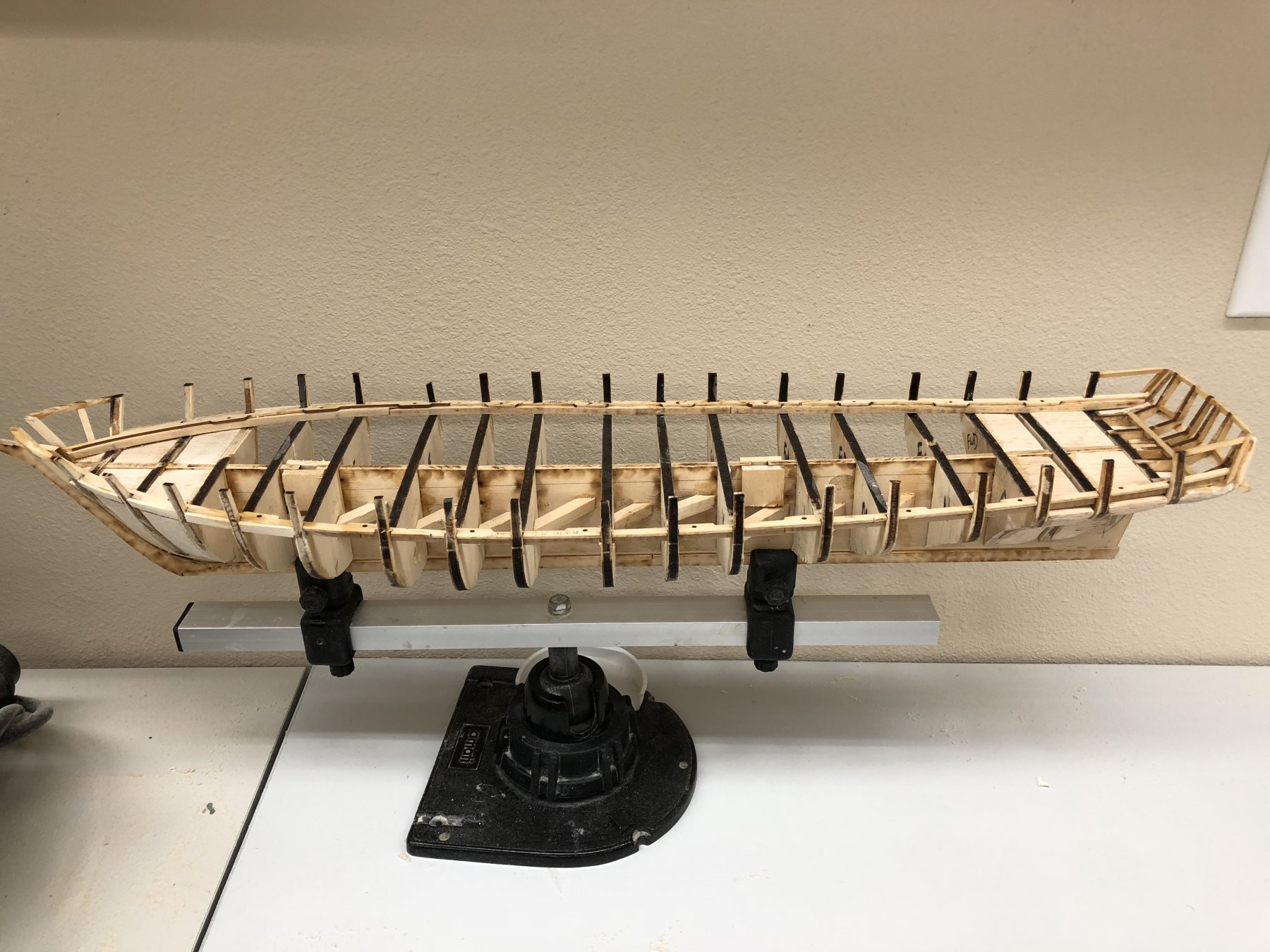
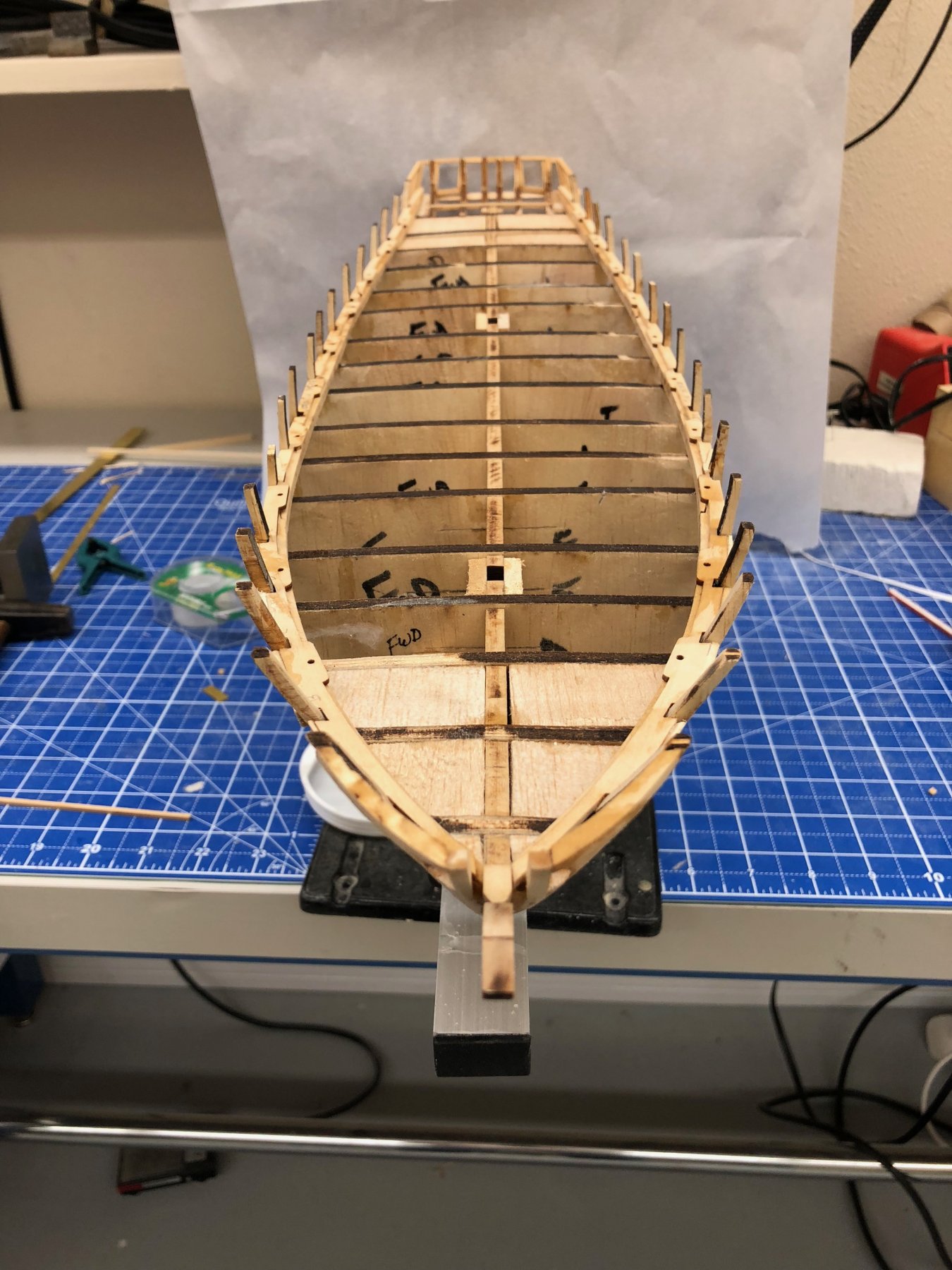
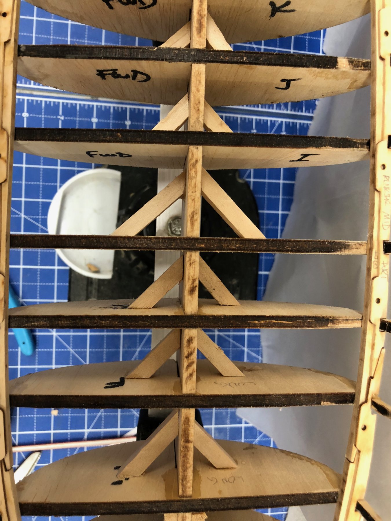
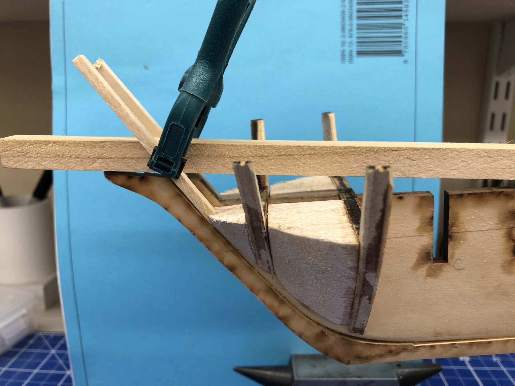
Hull structure is complete, waterways and planksheer installed but not yet finish sanded or painted. As suggested in several build logs I have been adding 1/16 X 3/16 or 1/32 X 3/16 pieces outboard of the planksheer to fill in the gap between the planksheer and where the bulwark planking will go. I added diagonal internal supports to the bulkheads after the waterway/planksheer installation to provide additional strength to the center keel/bulkhead structure. I prefer the diagonal reinforcements to longitudinal ones because they are easier to install and do not require precise cutting to "just" fit between the bulkheads. As long as you have the capability to cut precise 45's you only have to get close on the measurement. I used 1/4 X 1/4s that I had laying around from something else. And I only broke one stanchion that I couldn't find the missing piece for - broke substantially more than one that were successfully (more or less) repaired. Next to add the 3/32 X 3/32 piece across the top of the stanchions and frame in the gun ports and sweep ports.

- Jim Rogers, Dwight and Tom E
-
3
-
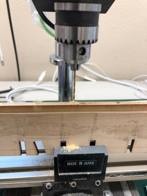
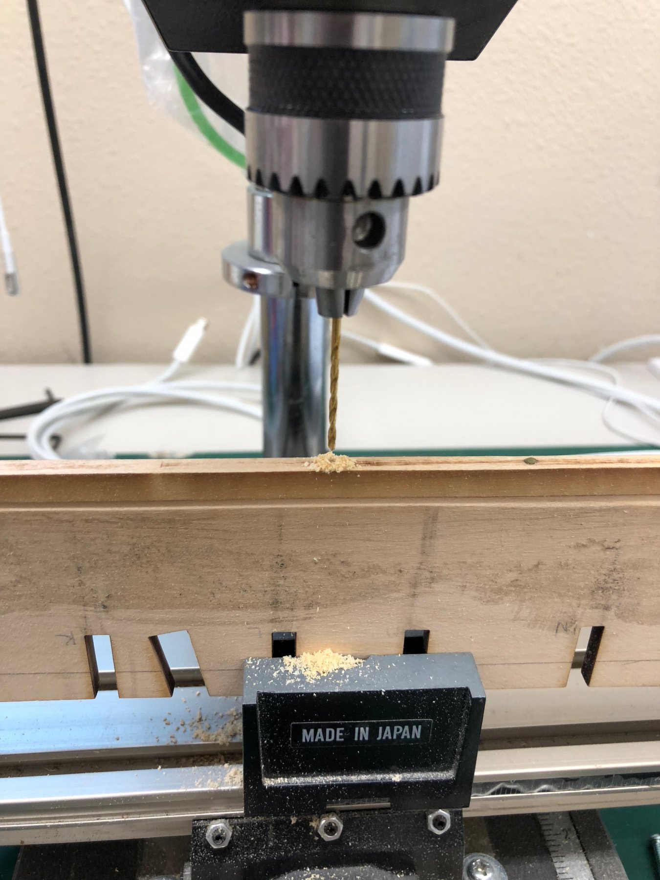
Thought it would be a good idea to drill pilot holes for the eventual mounting screws before mounting the bulkheads on the center keel so I used the drill press to put in two 1/16" holes approximately equidistant from the stern and fwd end of the straight keel section. That will make them centered under the straight part of the keel.
- Tom E, Tigersteve, GrantGoodale and 1 other
-
4
-
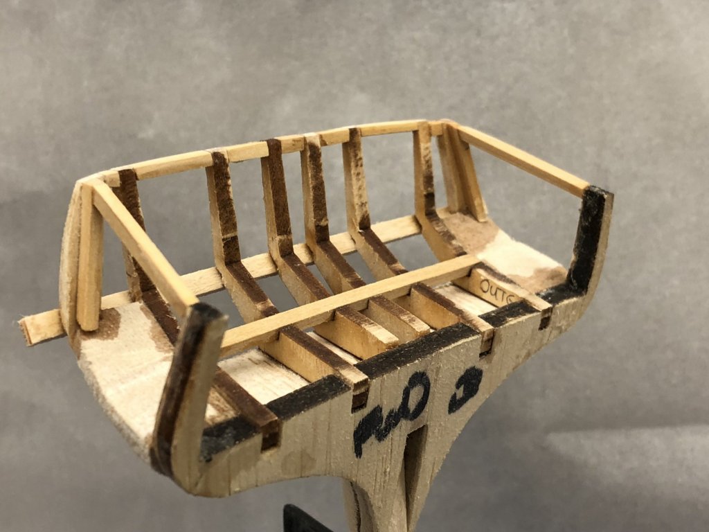
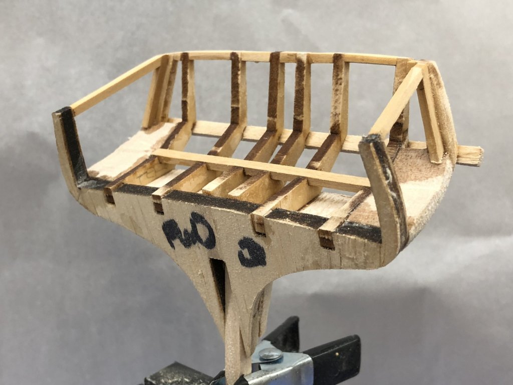
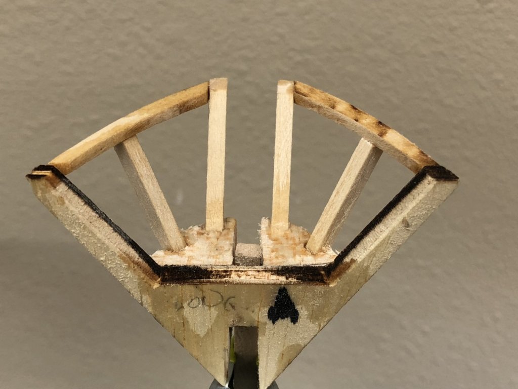
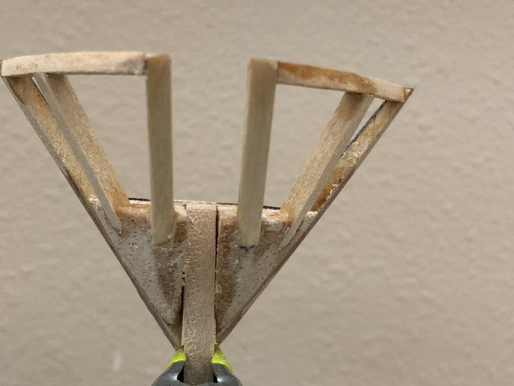
Here is the final version of BH Q before installation on center keel. Added the framing around the gun ports. I used the inner timbers on the drawings as the starting point for measurements. I believe I got the timbers in the correct place. Am not so sure about the quarter stanchions so thought measuring from the center would be more accurate. Will have to wait until the stern is planked to "know for sure" who accurate I was.

-
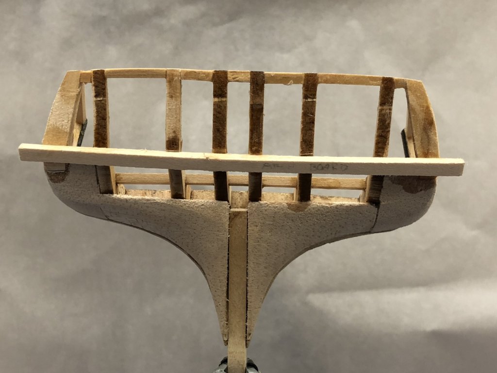
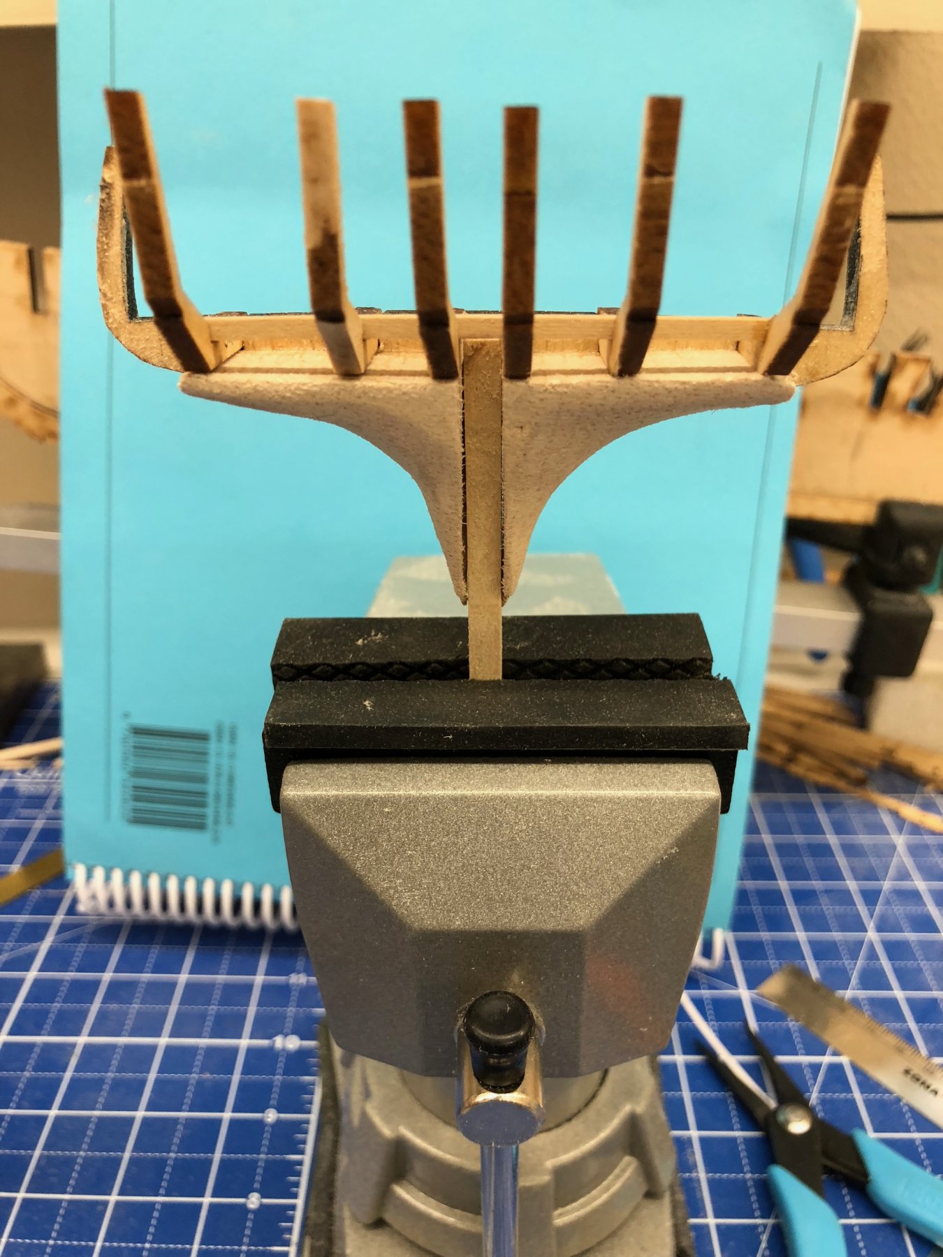
Completed the stern structure on BH Q. Have to add the gun port fairing still and will leave the arch board "as is" until planking the stern is completed. Also created filler pieces for BH P and O since I had plenty of spare balsa and it was kind of fun sanding away.
- JpR62, JerseyCity Frankie, Dwight and 1 other
-
4
-
Since there are many sources which indicate that a second filler block between BH A and B is a useful addition I built one and then decided that if two are good, three is better so I made a filler for between BH B and C as well.

- Tom E, kier and Jim Rogers
-
3
-
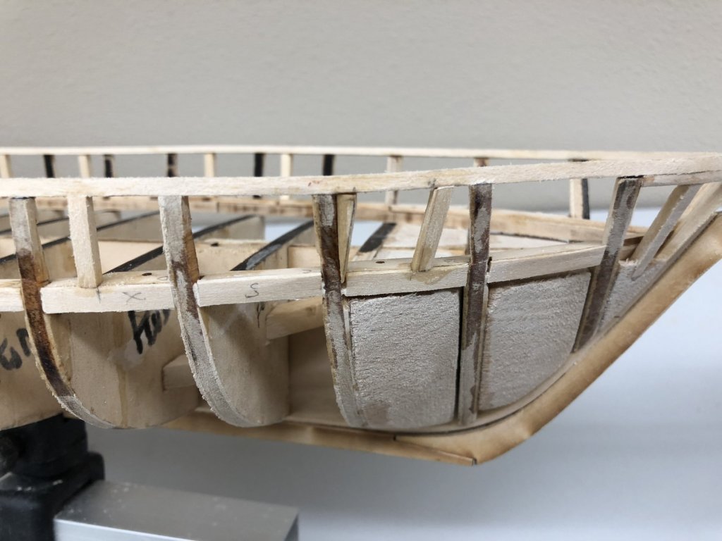
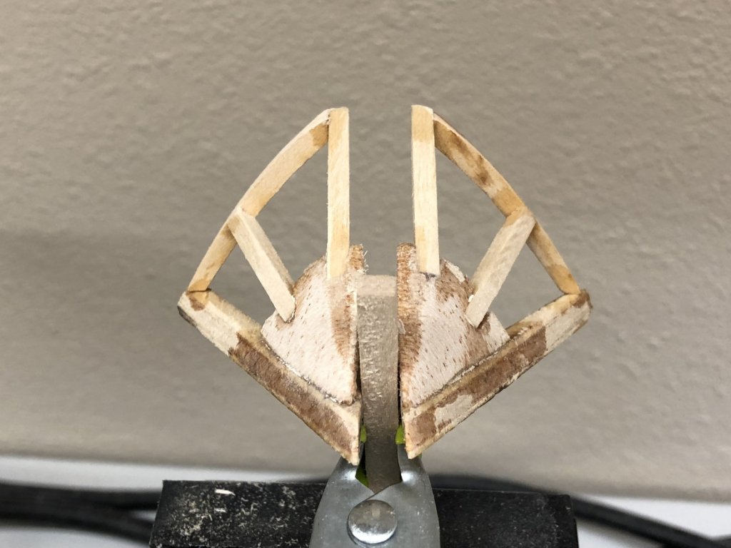
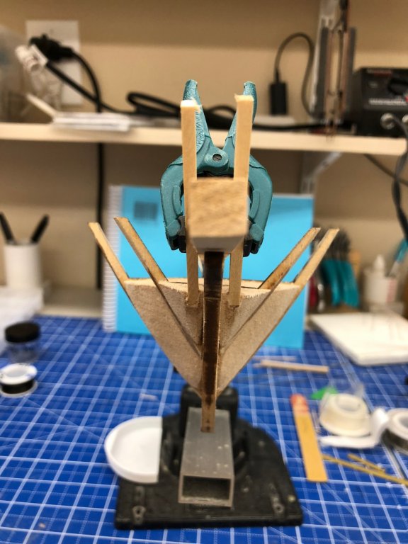
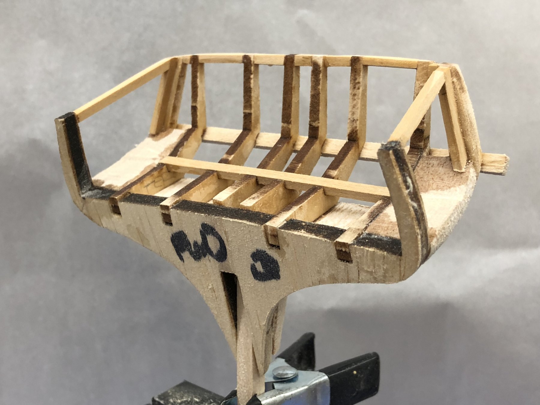
Stern filler is considerably more of a challenge than the bow. I had a hard time, even with all the build logs to look at, figuring out what this was all supposed to look like when completed, especially the quarter stanchions. Hopefully I have everything figured out correctly. The first filler block and the stern timers went together "okay". Even with the notches in BH Q and the support beam across the six stern timbers, things did not look very symmetrical. Getting the inner filler pieces "matches" took a lot of sanding and checking. I used a homemade sanding stick made from a tongue depressor with one end squared off and some 80 grit sandpaper contact cemented to it as my primary shaping tool. When I got to the really curvy parts I had to revert to 180 grit wrapped around my index finger.

- Jim Rogers, kier and Dwight
-
3
-
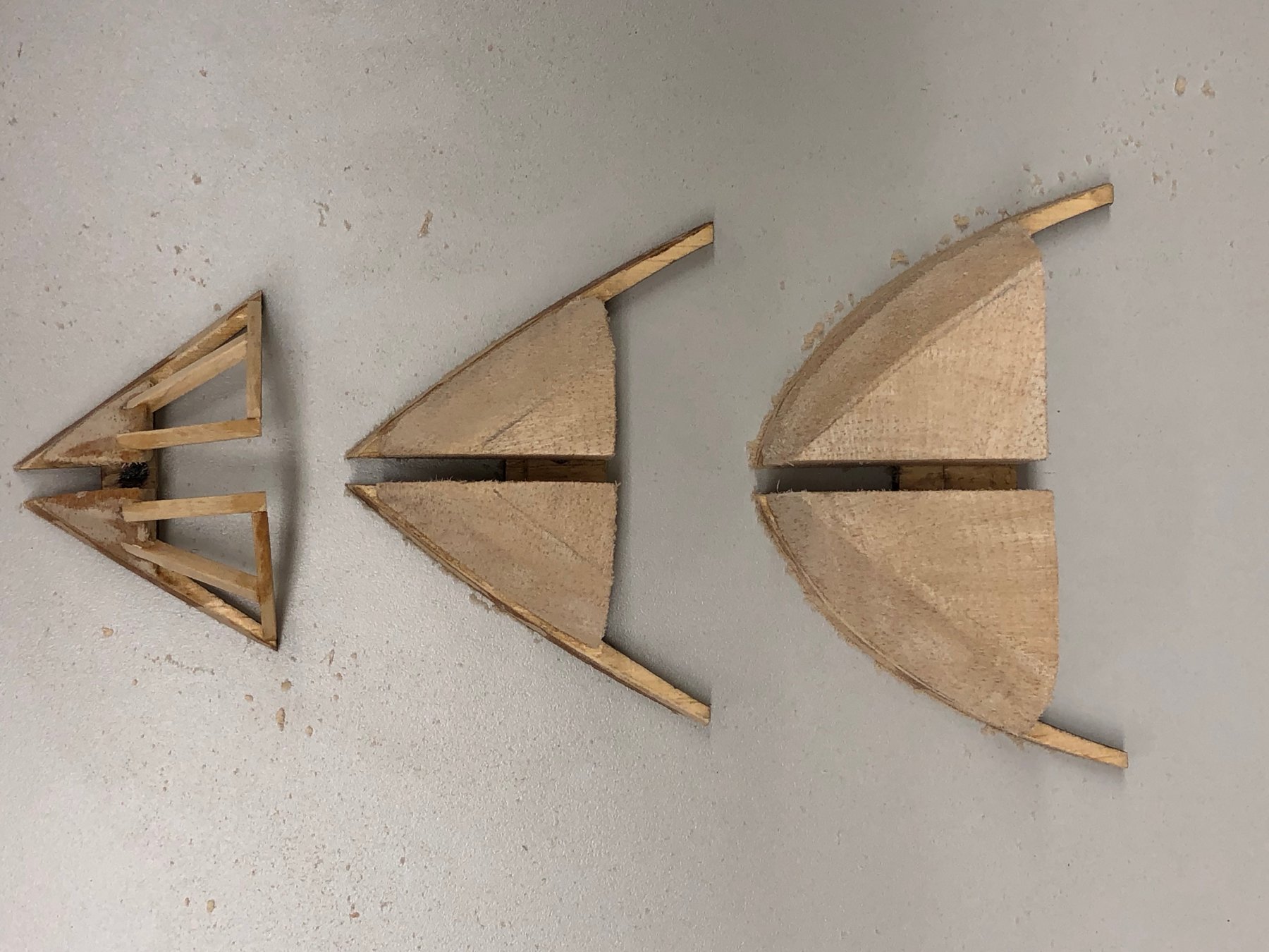
Bulkhead A and bow filler pieces, knightsheads, timberheads, and support pieces assembled and ready for installation on center keel. Doing this work prior to gluing BH A to the center keel is definitely the way to go IMHO. Much easier to avoid "unintended consequences" elsewhere on model. Here are three views of the completed structure.
-
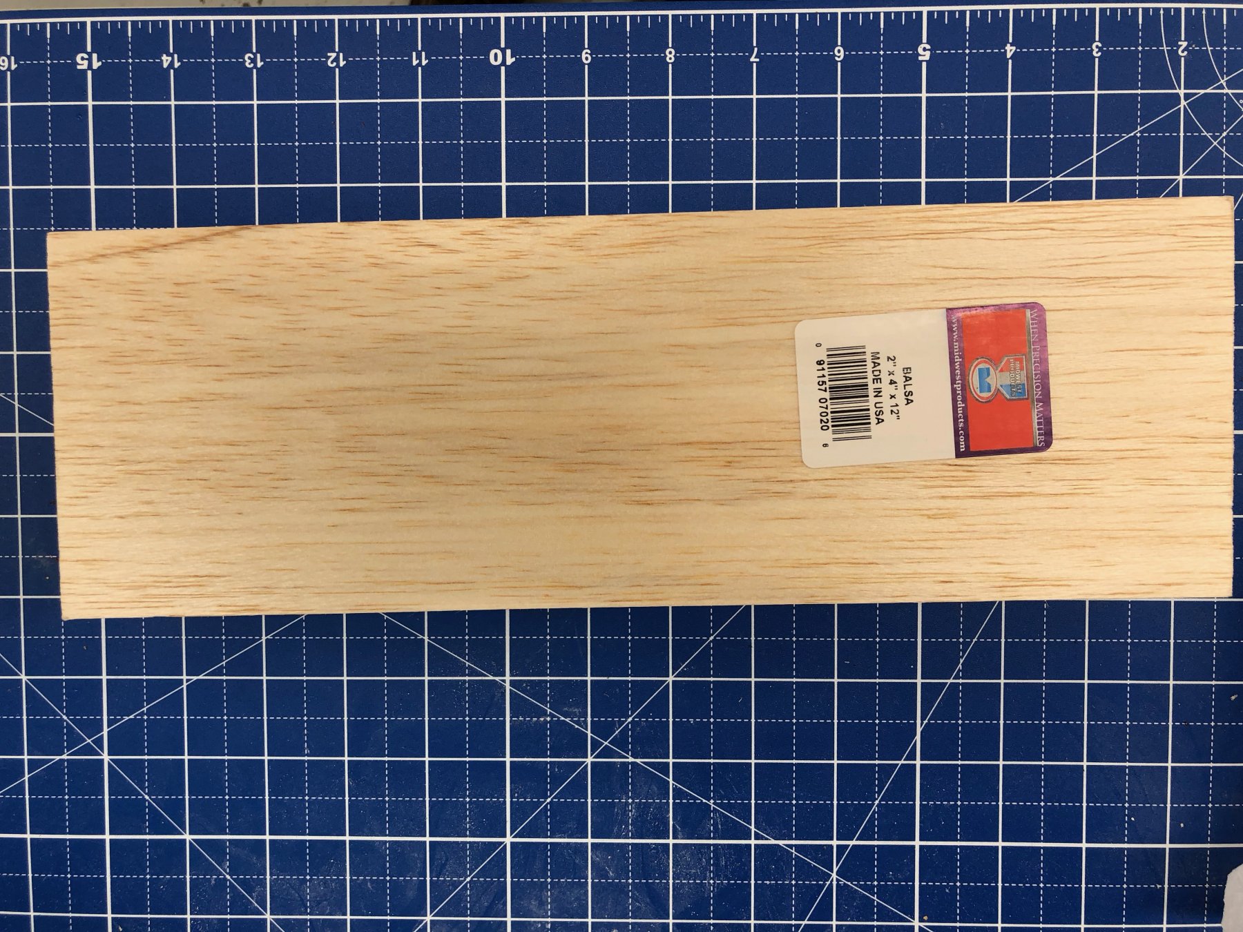
The "real ship construction has begun. I fashioned and installed (on the bulkheads only, nothing is permanently attached to the center keel yet) the forward filler block and, taking the advise from several build logs) a second filler block between BHs A and B.I have the knightsheads on each side of the bowsprit (standing in for the bowsprit is the 5/16" X 5/16" piece that will become the bowsprit). Letting this dry (and working on the second cutter). Will add then other timberheads and the laser cut support when this is dry. Filler blocks were cut from balsa wood 2" X 4" X 12" slabs. Balsa is really easy to sand and since I don't have a scroll or band saw that is a good thing. I would not want to try and shape the blocks that came with the kit without a "power assist". Below are pictures of the knightshead and filler blocks installed.


-
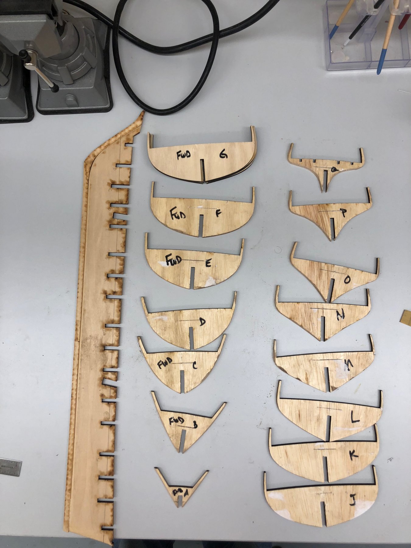
The glue job on the false keel/real keel came out fine, just a few places where the glue needed to be removed. I also marked the reference line on the false keel. Sanded the bevel on each of the bulkheads, removed the bulkhead drawings (mostly), marked the reference line on the bulkheads and the side of the bulkhead that faces forward so the next step is actually putting the bulkheads onto the keel. Am going to reread some of the build logs on this step before proceeding - do NOT want to screw up this part.


US Brig Niagara by cdrusn89 - FINISHED - Model Shipways - 1/64 scale
in - Kit build logs for subjects built from 1801 - 1850
Posted
Thanks Ric. I am not having much "fun" working with the airbrush - at least not yet.