Fritzlindsay
-
Posts
96 -
Joined
-
Last visited
Content Type
Profiles
Forums
Gallery
Events
Everything posted by Fritzlindsay
-
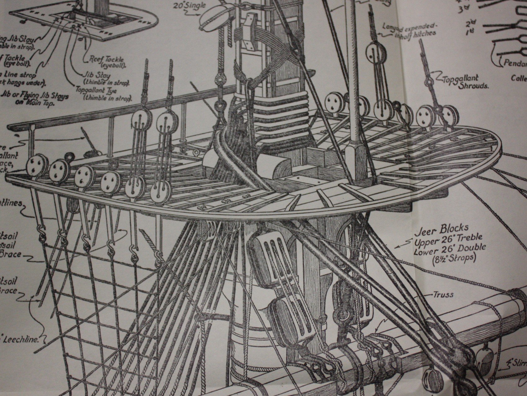
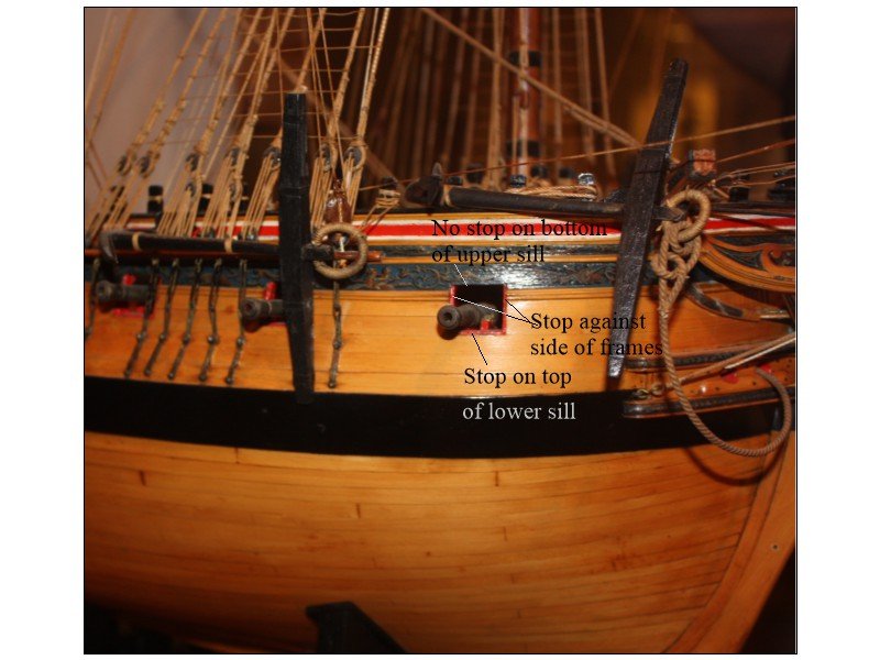
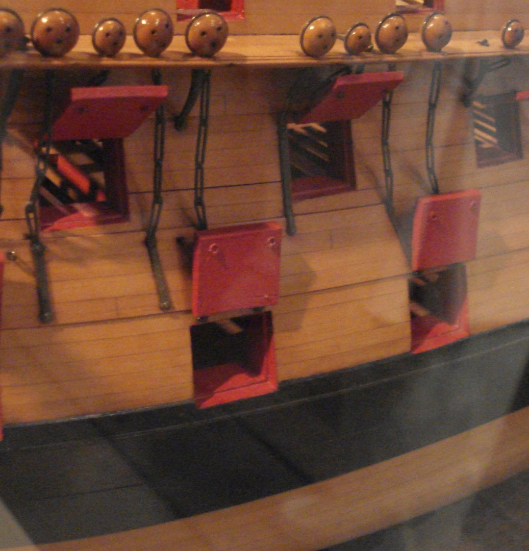
The port is framed by hull frames on the sides and sills on top and bottom. There are three thin (1"-1.5" thick) linings/stops on the sides and on top of the lower sill that are recessed so the outer layer of planking on the lid winds up flush with the surrounding planking, be it wales, or other planks. The lids had an inner layer with planks running vertically and the outboard layer ran horizontally to match the hull planking. Unlike many build logs, there was no lining on the bottom of the upper sill. Studying contemporary models confirms this. Drawing below probably is a better description than words. Fritz From Euryalus Volume II page 8 Preble Hall contemporary models
-
Does Harpy also have a waterway between the margin plank and spirketting? Thanks Fritz
-
None taken.😀 Sorry, sometimes words need a smiley face as nothing negative was intended. My bad Fritz
-
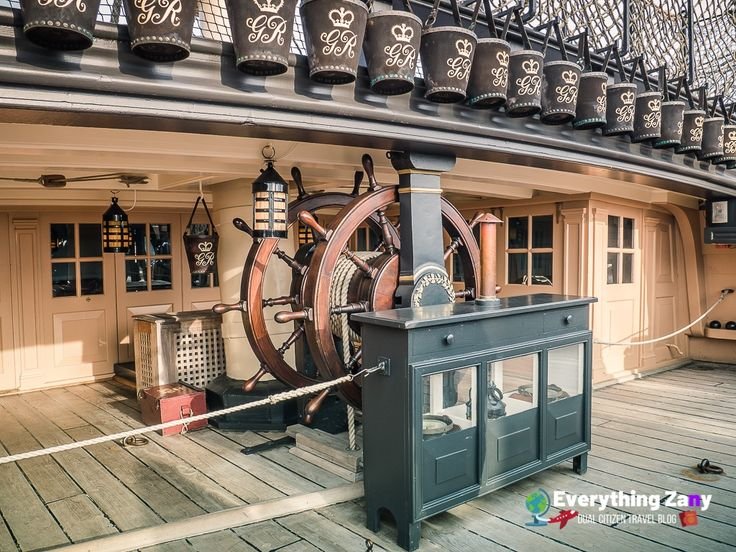
Is there a reason you question this? Even her original 1765 version before the massive rebuild in 1803 had two wheels as can be seen in the contemporary model from RMG below. Victory today showing two wheels
-
Thanks Gary I wonder why this would be the case. The same size men crawled up the shrouds and the ratlines. If the ratlines were basically nothing more than rungs on a ladder why would they have to be different sizes? I trust the information is correct, but wonder if there is some other reason such as more men on a given rung on the forward masts, thus putting double or triple the strain. Fascinating stuff one way or the other. Doing a little digging, a 3/8 inch fiber rope has a working load of a little over 800 pounds and 1/2" about 1400 pounds. Even with three men on one rung, wouldn't 800 pounds working load be sufficient to support their weight without having to go to the larger diameter rope? I am guessing there must be more to this. Now to add to my confusion, the picture above states all ratlines are 0.01mm. Assuming the model has a scale of 1:64 that makes them the full size equivalent of 0.025" diameter or less than one tenth of what they should be. My math may be off on this so any help here would be appreciated. Thank you again. Fritz
-
Looking at your shrouds and ratlines with the neatly done clove hitches, it brings up a question that is no doubt a simple one, but I cannot find an answer. What was the typical diameter or the circumference of the ratlines? I am guessing it would be about the same for most if not all eras and nationalities or on any size ship or shroud even if the shroud circumferences varied from mast to mast. Thanks Fritz
-
Small hand drill should work without problems. Fritz
-
Thanks for posting these photos. They give corroboration that actual ship's boats did not ordinarily have thwarts without any tholes at all. Fritz.
-
Rigging Mast Deadeyes Order
Fritzlindsay replied to acaron41120's topic in Masting, rigging and sails
What you are saying makes a lot of sense, but wouldn't that depend on the ship, nation and era. According to James Lees, in The Masting and Rigging of English Ships of War the mizzen stay on English warships did not go to the deck before 1805. Fritz -
Rigging Mast Deadeyes Order
Fritzlindsay replied to acaron41120's topic in Masting, rigging and sails
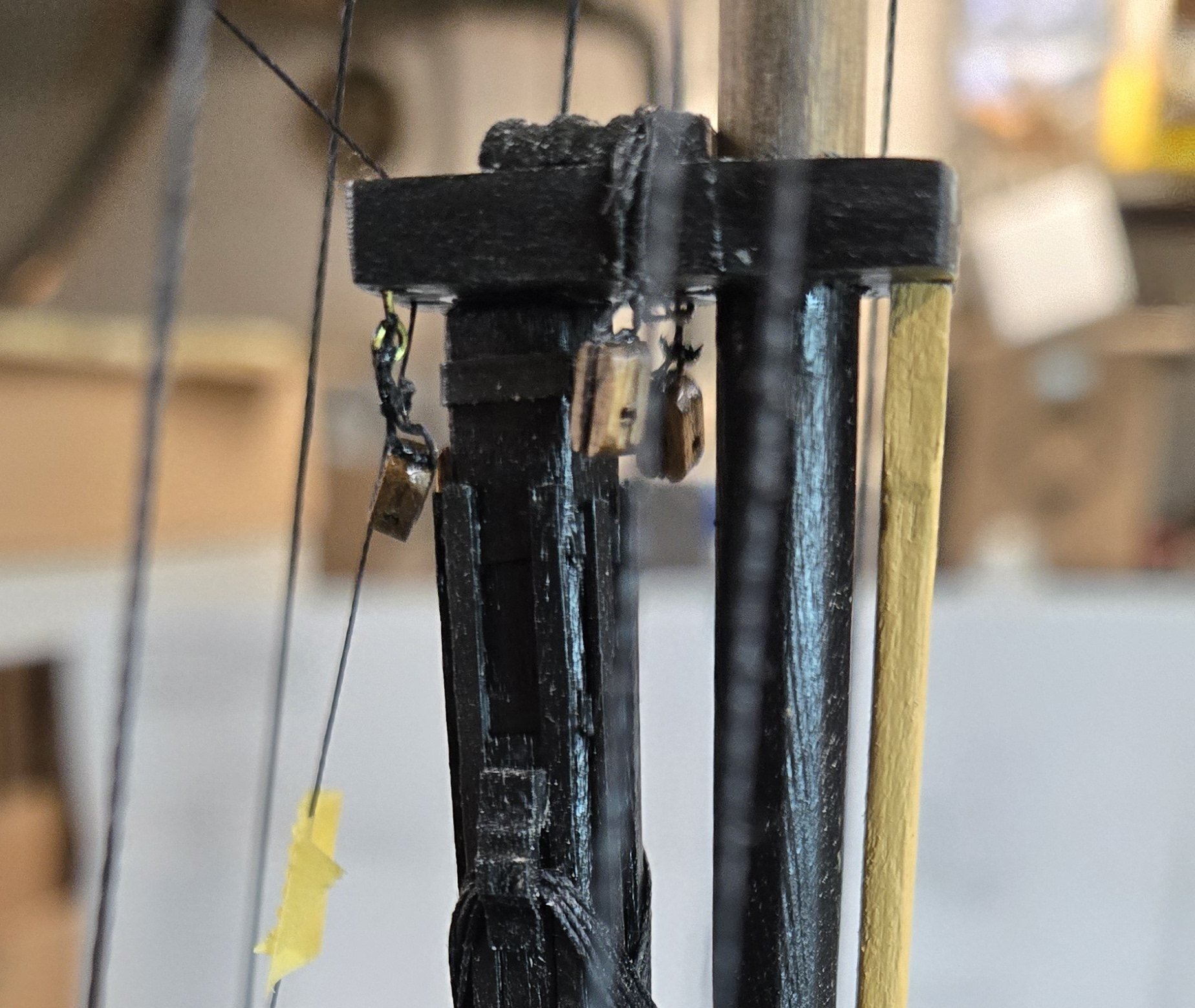
I may be misinterpreting your question but here goes. Installing topmasts after the lower shrouds are set up makes sense, but not the tops. The lower shrouds usually go through the tops/platforms so how could you rig the shrouds and deadeyes before hand? The picture may not be appropriate for your model as it is a drawing by C.N. Longridge in his book about building a model of the Victory. Fritz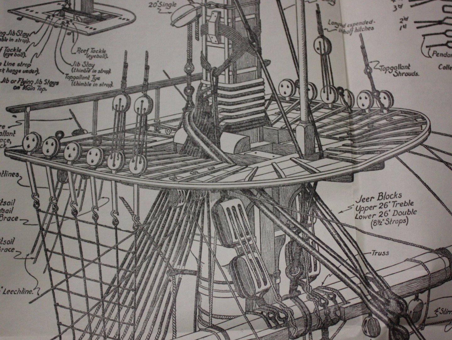
-
I may be wrong, but are these blocks upside down? Thanks Fritz

-
Atlantic by Bluejacket rigging question
Fritzlindsay replied to bruceh's topic in Masting, rigging and sails
Five, maybe consider re-rigging the problem areas with a good quality miniature rope. Just a thought🤔 Fritz -
Thanks for posting this Craig.
-
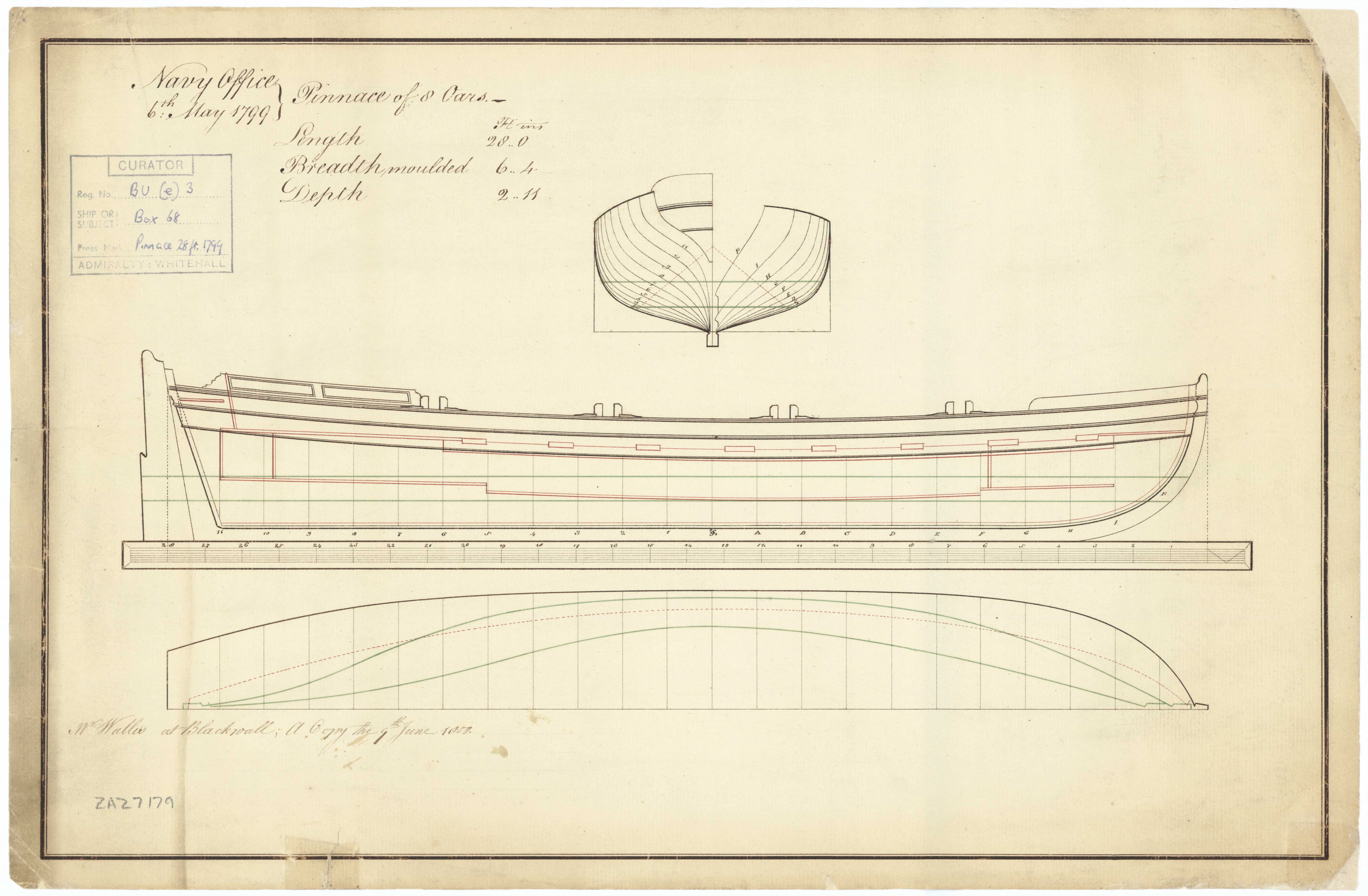
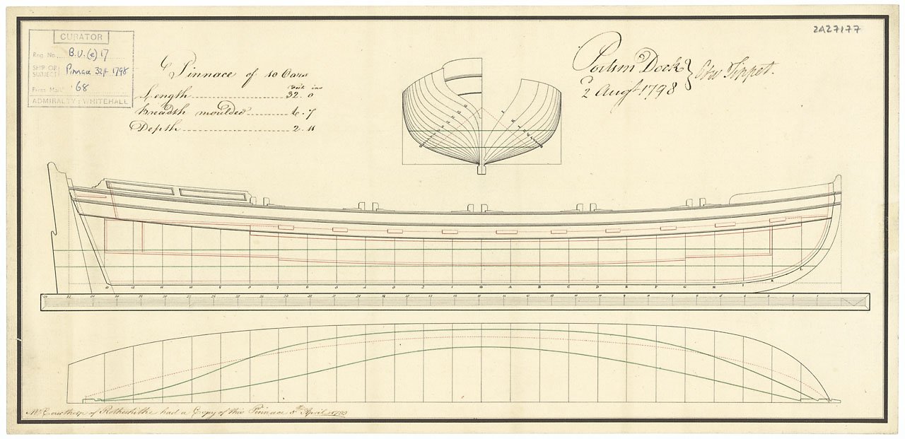
Druxey Would you agree that pinnaces would always/usually be single banked, set up with one thole per thwart as in the plans in post #17, alternating, rather than two tholes for one thwart and no tholes for the adjacent thwarts? Thank you
-
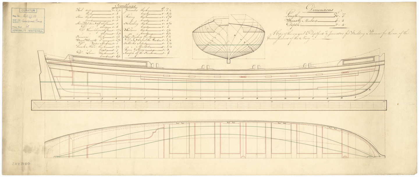
There are a lot of contracts for ships, but I agree with you that boat contracts do not appear to be so common. I have seen contracts for a pinnace and yawl of 1790 and a contract for long boats from 1695 that include scantlings, so they do exist, but they are not so easy to find.
-
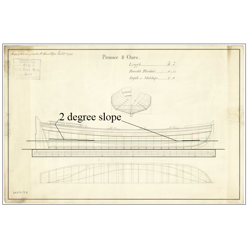
Very true, but so will a platform as they are sloped a couple degrees toward midships which would allow the water to run to the bottom of the boat. Fritz
-
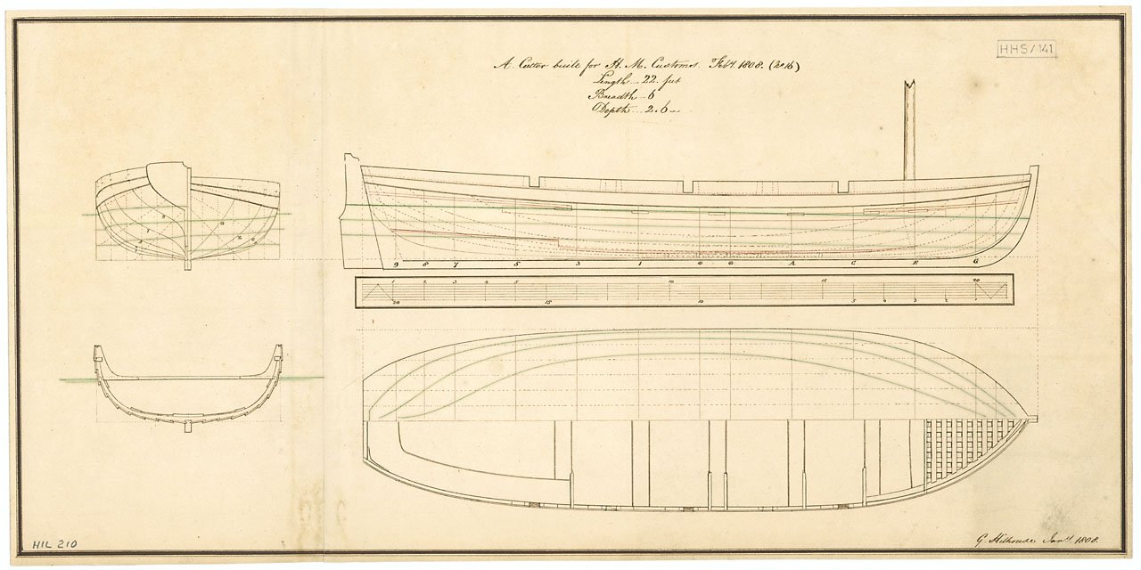
Thanks Chris What you say makes sense and am happy to know you were able to find plans that show them. My quest to find any had been without success until about an hour ago. I found a cutter plan that shows a grating in the bow and I am very happy that I finally did😀 Thanks again
-
Thanks for all the photos and apologies for the confusion Kenchington. By modern I was referring to today's kits of 18th century boats. A big problem would be for launches and longboats that had a davit aft. The grating would have to be cut away for the davit to pass through to the chocked pin. It would be less problematic if the platform was a series of simple planks. In any case I am still searching for contemporary evidence of gratings ever being used instead of platforms on 17th to early 19th century ships' boats. Fritz
-
I agree Druxey but there are a lot of plans that do not show the offset tholes in the overhead view which might be the reason some kits get it wrong as in the photo above in post #17. Fritz

-
Why do some modern ships' boat models show gratings fore and aft instead of solid platforms? So far I have not been able to find any contemporary models or plans that show other than solid board platforms. The solid platforms are slightly sloped so would not accumulate water. The purpose of having gratings on the ship is to allow air below decks but what would be the purpose on a boat? I would appreciate it if anyone can share information based on contemporary sources showing/describing gratings on a ship's boat. Fritz
-
Just tuned in to your build. Lots to compliment on your work but one thing that jumped out to me is that you correctly tapered the thickness of the wales at the rabbet at the stem which is more often than not ignored in the builds that we see. Great job! Fritz
-
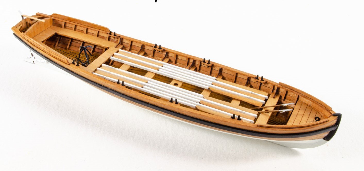
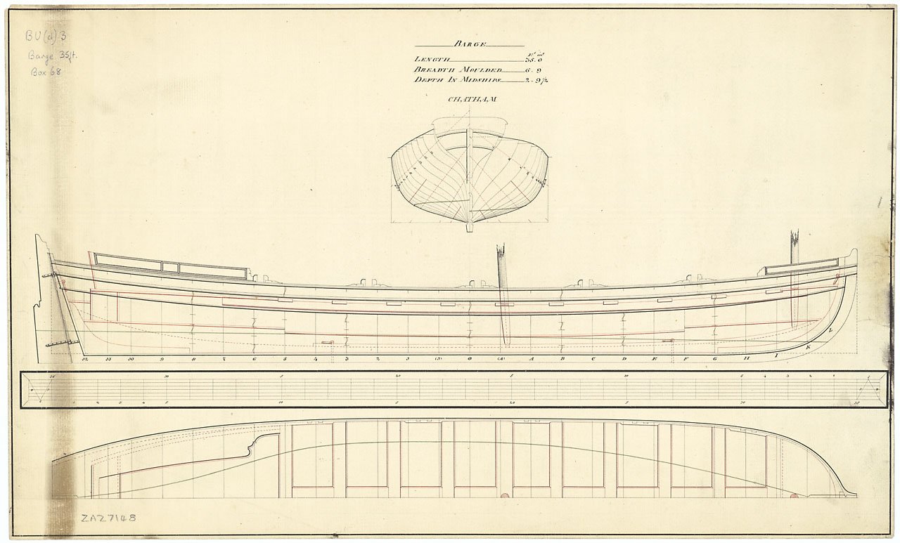
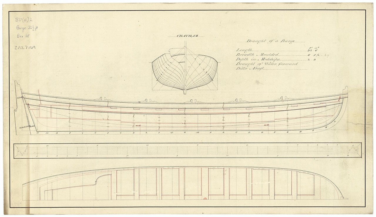
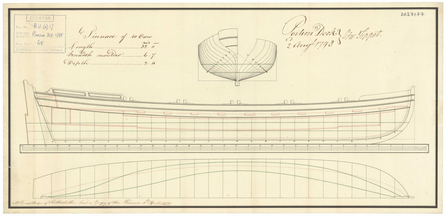
Thanks, it appears there is agreement that pinnaces were single banked and the pinnaces that show some thwarts with no tholes are incorrect. An example is below. Pinnace with possible missing tholes Another question. Were barges ever double banked? I cannot find any contemporary information that is other than single banked. Two examples of the many that I found showing the single banked design follow:
-
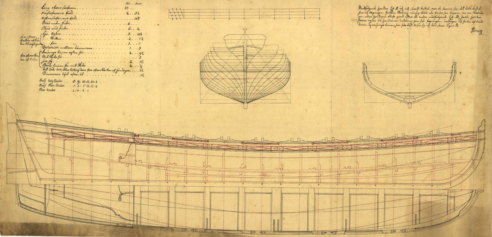
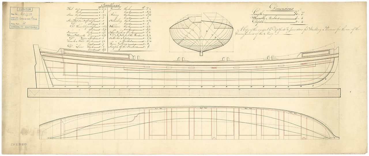
You may be right, but I am betting there would still be tholes for single banked rowing on every thwart when used for other purposes. Based on the contemporary drawings which I am trying to reload here, there is one thole for every thwart on the first two plans. The third drawing shows the alternating tholes on the top view, but leaves out any tholes on the side view. Sorry they do not appear to have been loaded properly in my previous post. Fritz

-
I am not sure if this has been addressed in the past, but I could not find anything so far. Apologies if this is a repeat. I have seen at least one supplier that offers kits for pinnaces with the tholes set up like a double banked boat on every other thwart. Why are there the alternating thwarts with no tholes at all? Contemporary drawings sometimes only show the tholes in the side view and it looks like every other one is missing, but I THINK this is being misinterpreted. Were pinnaces ever built for two tholes on a single thwart then no thole for the next thwart? Thanks Fritz The first and third drawings are easy to interpret, having two views with the alternating thole locations. The middle drawing might be problematic as the tholes are only shown on the elevation view so I can see how this could be misinterpreted if the pinnace was single banked. With a breadth of only 6'-7" I cannot see two rowers on one thwart, then every other thwart with no rowers.

-
It is really nice to see the tholes in place for a single banked set up properly done. Fritz
- 4 replies
-
- 1
-

-
- Admirals Barge
- Vanguard Models
- (and 2 more)