Fritzlindsay
-
Posts
96 -
Joined
-
Last visited
Content Type
Profiles
Forums
Gallery
Events
Everything posted by Fritzlindsay
-
I hope someone has experience with this. Liver of Sulfur blackens clean copper instantly but I have never had luck using it to blacken brass. I have read that adding iron powder helps, but I have not tried it. Fritz
-
Are these contemporary drawings from the 18th or 19th century or are they modern photos or images? Thanks Fritz
-
You are probably correct Gregory, but the original post asked a specific question about the width of planks and made no mention of a kit. Apologies if the response and drawing were inappropriate. Fritz
-
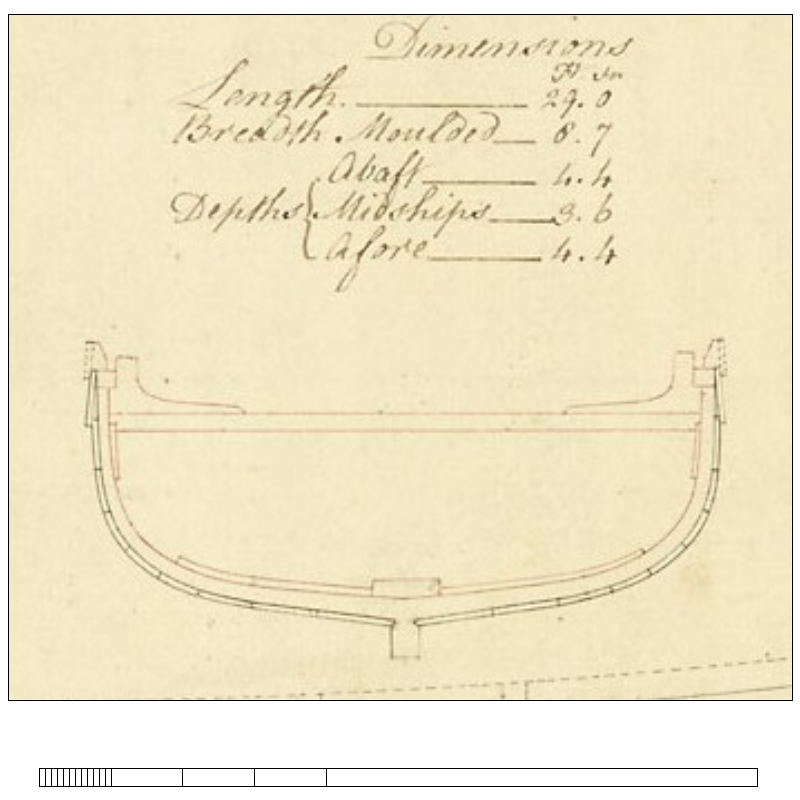
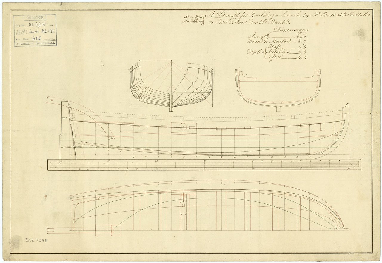
Looking at a number of builds, the tendency seems to be having too many planks that are not broad enough. While the drawing from RMG below is a launch rather than a long boat, it is indicative of the plank breadth. The garboard is about 13 inches broad at midships and the other planking about 7.5" broad at midships. I imagine this varied from boatyard to boatyard to some extent, but might be a good guide. Fritz
-
No Ideas has a great point about voids and pockets in plywood. Aircraft plywood or high quality birch plywood would be good choices for the bulkheads. For planking, softer wood like basswood is prone to dents but coppering will cover these. Paint will not hide any dents so maybe consider a harder wood above the water line for the hull planking. Fritz
-
Is your build going to be plank on bulkhead or plank on frame? Fritz
-
The shape of the rabbet continuously changes so it approximates the continuation of the angle of the frames to some extent. The edge of the garboard that goes into the rabbet sometimes varies a bit as well. See the post #4 at https://modelshipworld.com/topic/25699-bearding-and-rabbet-lines/#comment-751551 There are a number of cross section plans at the Royal Museum Greenwich Collections website that you might find helpful as well. One example is below. Fritz
-
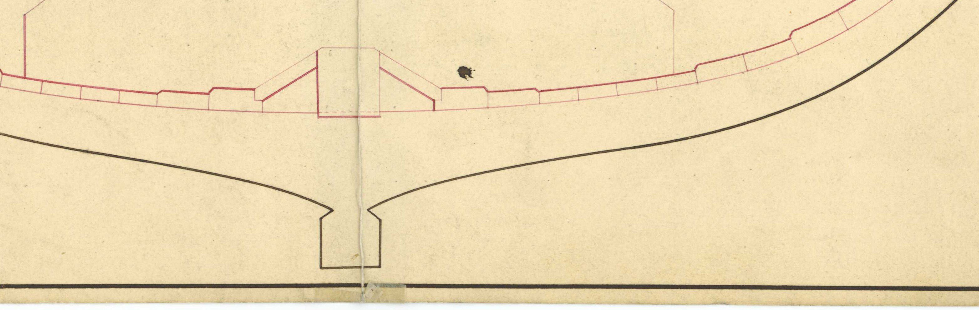
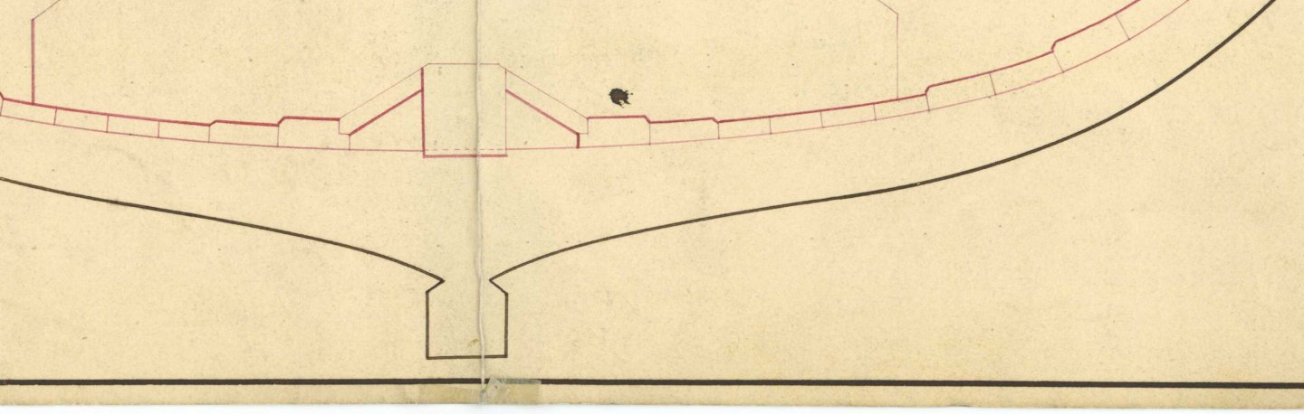
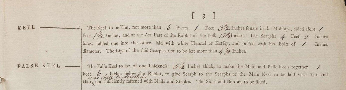
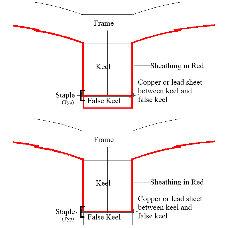
I am not sure if I am interpreting the contracts correctly where they describe the coppering of the keel and false keel. Of importance is that the wording is that the Ship is to be coppered before the False Keel is put under. To me it appears they were both coppered on some ships and but the false keel was not on other ships. Would coppering the false keel prevent it from serving its purpose, that is, tear away from the keel if the ship grounds? The sketch is how I envision this, but hopefully some member can confirm or correct any errors. Thank you Fritz Acquillon (32) Diana (38) Some contracts do not mention coppering the false keel, but others do, so I am not sure which. if either, was predominant as the contracts in question were both from the late 18th century. The first is for Diana (38) 1794 and does not mention coppering the false keel. This next contract was edited to include sheathing the false keel. The sketches below are how I picture the two options but they may be totally wrong and I welcome any corrections.


-
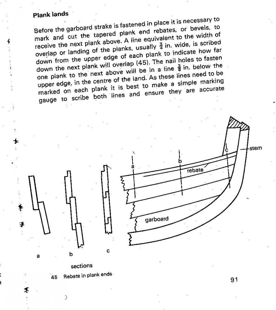
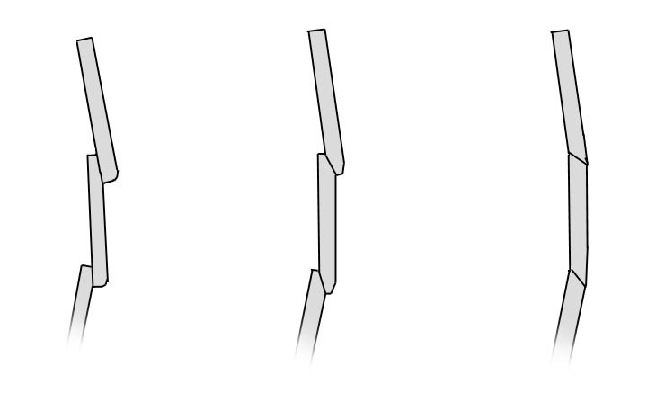
Regarding lapstrake or clinker planking I know there was a diminishing of the overlap near the bow, but was there also a similar gain at the stern? Thanks Fritz
-
Scrapers can get into corners that sandpaper will not reach. Sanding is one option, using a scraper a better one at times or a combination of both depending on the wood, space to work, etc. Fritz
-
Hello Mike Thank you for sharing your idea. Weren't the ladders laid down at an angle rather than straight up and down and wouldn't they rest on the deck planks rather than having the ladder side rails hanging some inches in space above the deck? Fritz
-
I don't know which videos you have watched but the planking tutorials here in the Articles section are well done and easy to follow. Also the attached which another member sent me might be helpful to you. Fritz Planking Project Dirk Debakker.pdf
-
Kirill explains it very well. I think if you recognize that the wales do not go on top of the other planking, but rather, are just thicker strakes of planking as he points out it easier to understand. The forward ends look to be below the water line on your model so possibly that is the problem rather than the aft ends at the galleries. As your model is not a real ship if you look at models in the Royal Museum Greenwich website it may be easier to understand. One example of a contemporary model by well known author James Lees is below and can be seen on the Royal Museum website along with others. Fritz
-
I have one that I rarely use as the holes are not consistently reduced from one size to the next and it only goes down to 0.020" Hopefully they have an improved version compared to the one they sold me many years ago. Hope Donna Byrnes can get the company up and running again as Jim's plate has been a joy to use. Fritz
-
When the shrouds come very close to each other near the tops, were they really tied off with clove hitches to every shroud? The shrouds are only a few inches apart so it seems it is not necessary to secure these uppermost ratlines to every shroud. Fritz
-
If you are going to rig her there is some great information in the rigging warrant for Alert 1777 at RMG that has a couple pages of detailed lists of rope and blocks that you might find beneficial. The first page is below. Fritz
-
The next time you build an English ship's boat, there are drawings at RMG of barges, cutters, launches, longboats, etc. and there is a full set of boat scantlings that you may find useful in the following books: Elements and Practice of Naval Architecture, Boats of Men of War, and Scantling of Royal Navy Ships. The last of these also has scantlings for English ships of all sizes from the 1719 Establishment into the 19th century. An example of a launch drawing from RMG is below. Fritz
-
Thank you Lieste. What pattern was used by the navy if the Gribeauval was for field artillery only. Fritz
-
WOW he has exorbitant prices for cannon barrels. Are any of his patterns correct? The Gribeauval system came into use in 1765 and they look nothing like what he is offering for that time period. Below is the Gribeauval pattern on the left and the chart on the la hoche website. Fritz
-
This seems very high priced. From the information they provide it looks like they only send the barrels, not the carriages. I have never paid more than about US$0.80 per barrel for 3D printed in 1:48 if I provide the 3D drawings. I found out there are a lot of STL drawings for cannon here at MSW available for free. https://thenrg.org/page-1075420 Hope they will add some Spanish and French gun pattern drawings in the future. There is a great string of posts here as well. Fritz
-
Naval History On This Day, Any Nation
Fritzlindsay replied to Kevin's topic in Nautical/Naval History
A day early but December 7, 1941—a date which will live in infamy Fritz -
Thanks Gary, Pages 376-378 in the Sim Comfort publication of David Steel's The Elements and Practice of Naval Architecture describes the use of chocks when discussing constructing frames and there is a full set of plans for each of the futtocks for 74 and 98 gun ships of of 1802 at RMG that show the chock locations rather than scarfs . I cannot find any other contemporary based information so far, BUT, seeing is believing. That you saw the scarfs in place of chocks is another reason I hope to get to visit her one day. Thanks for sharing! Fritz
- 10 replies
-
- 1
-

-
- Victory
- cross-section
- (and 1 more)
-
Was lapstrake planking used on English ships in the 18th century? I know some ship's boats used this kind of planking and very early ships used this, but were any of the English brigs and other smaller ships built using this method of planking? Thanks Fritz
-
John, I did more research and the frames in the kit are incorrect for Victory in several aspects, including ignoring using scarphs instead of chocks. From what I could find scarphs were used instead of chocks in earlier centuries on large ship frame building. Fritz
- 10 replies
-
- 1
-
-
- Victory
- cross-section
- (and 1 more)
-
Beautiful work Chuck One question regarding the breechings, wouldn't it have been easier to use a knot or half hitch around a ring bolt like on the actual ships? I know the knots were replaced with double seizings in the 19th century, but for 1752, on this size ship, was there a prescribed method? Thank you Fritz