SJSoane
-
Posts
1,652 -
Joined
-
Last visited


.thumb.jpg.62d1d69fed1f32364417cb1f9cdeb009.jpg)


-
 Javelin reacted to a post in a topic:
HMS Bellona 1760 by SJSoane - Scale 1:64 - English 74-gun - as designed
Javelin reacted to a post in a topic:
HMS Bellona 1760 by SJSoane - Scale 1:64 - English 74-gun - as designed
-
 Speedy reacted to a post in a topic:
HMS Bellona 1760 by SJSoane - Scale 1:64 - English 74-gun - as designed
Speedy reacted to a post in a topic:
HMS Bellona 1760 by SJSoane - Scale 1:64 - English 74-gun - as designed
-
KARAVOKIRIS reacted to a post in a topic:
HMS Bellona 1760 by SJSoane - Scale 1:64 - English 74-gun - as designed
-
dvm27 reacted to a post in a topic:
HMS Bellona 1760 by SJSoane - Scale 1:64 - English 74-gun - as designed
-
Mike Y reacted to a post in a topic:
HMS Bellona 1760 by SJSoane - Scale 1:64 - English 74-gun - as designed
-
yvesvidal reacted to a post in a topic:
HMS Bellona 1760 by SJSoane - Scale 1:64 - English 74-gun - as designed
-
Cpt.Barbossa reacted to a post in a topic:
HMS Bellona 1760 by SJSoane - Scale 1:64 - English 74-gun - as designed
-
WalrusGuy reacted to a post in a topic:
HMS Bellona 1760 by SJSoane - Scale 1:64 - English 74-gun - as designed
-
chris watton reacted to a post in a topic:
HMS Bellona 1760 by SJSoane - Scale 1:64 - English 74-gun - as designed
-
Thukydides reacted to a post in a topic:
HMS Bellona 1760 by SJSoane - Scale 1:64 - English 74-gun - as designed
-
 Gary, you and I are some of the old timers on this site. When I first started, your work hugely inspired me. I will never forget panicking over how I would make hook scarphs for the wales, after I had devised all sorts of jigs that never really worked. Then I saw your posts on hand cutting the scarphs, and how they matched edges perfectly. I had a go, and after a few failed attempts I was up and running! So we just share inspiration back and forth. We'll both get there in the end. druxey, you might be right about ventilation. The captain no doubt wanted to maintain higher "gentlemen" standards than the officers a deck below with only one internal door. Kidding aside, it is not clear to me if the lights in the quarter galleries could be opened for ventilation or not. The ones along the aft side of the upper deck had recesses above, into which a sash window could be raised by about 8-10 inches. but I don't know if a recess over the quarter gallery lights would be physically possible. Interesting question! Yves, thank you for your kind comment. I seem to be buying craftsmanship at the expense of a timely build. I might just be slowing down because of age, but the trim and fit, trim and fit, trim and fit sequence for every part seems to be taking forever these days. Best wishes, Mark
 -
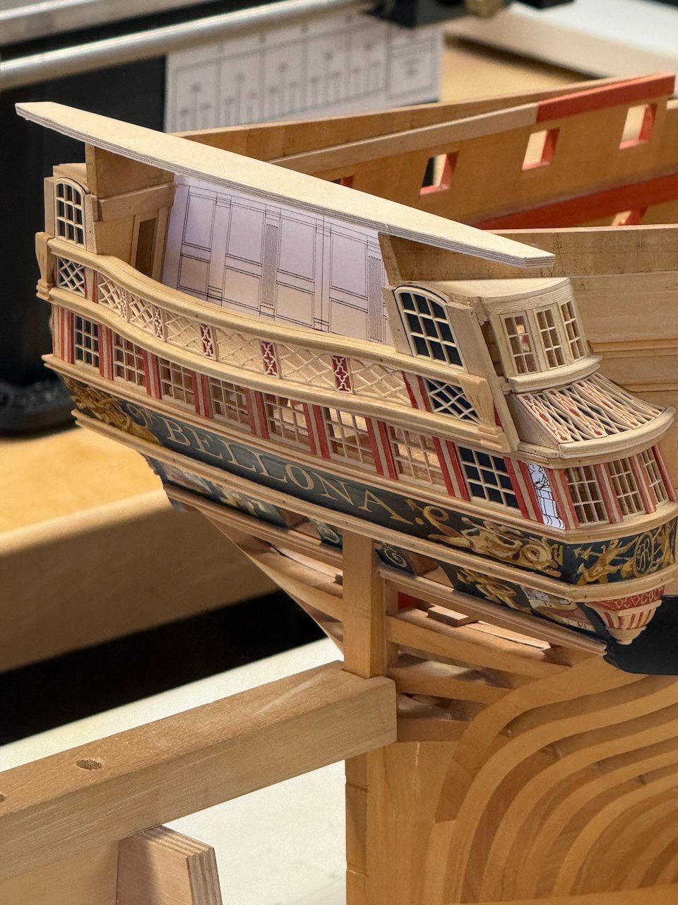
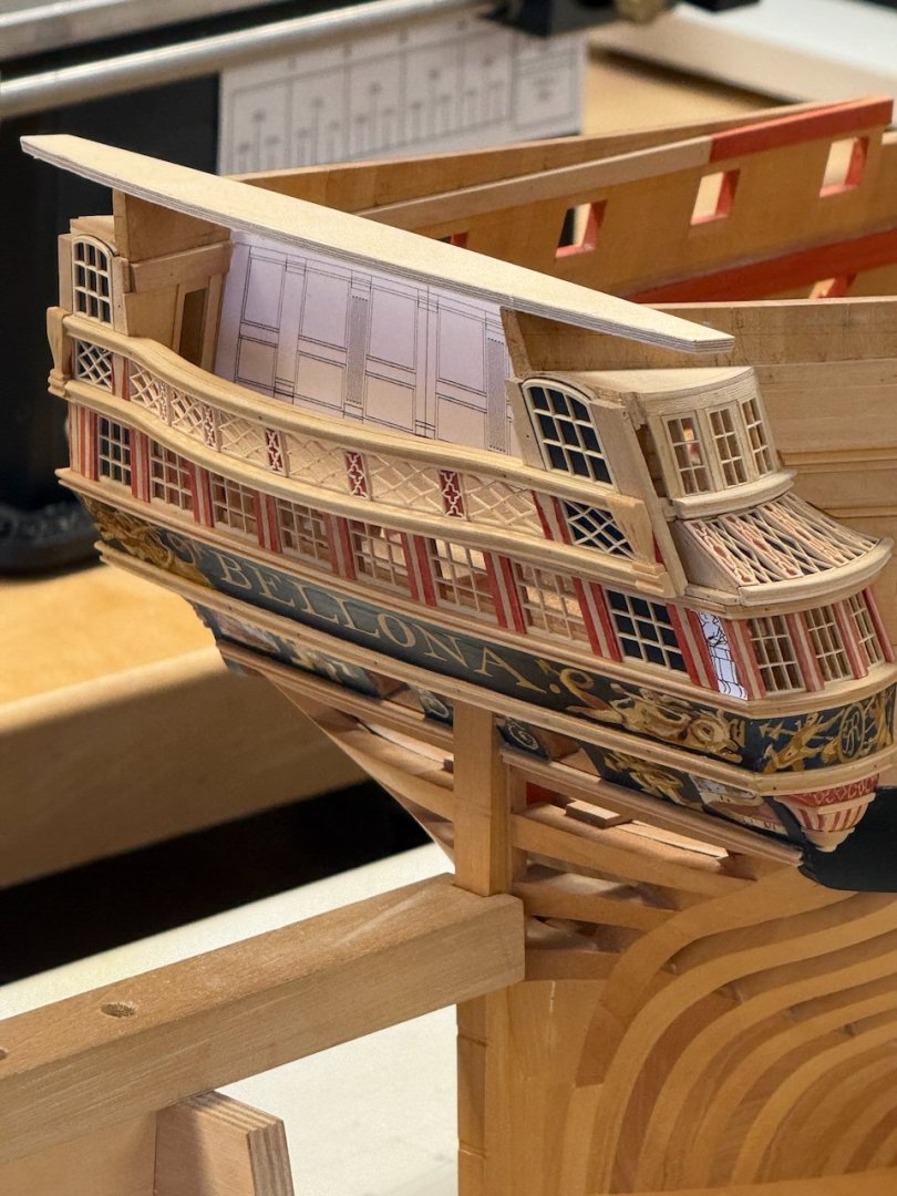
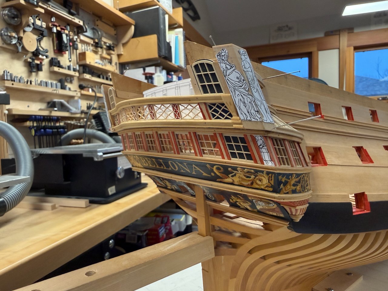
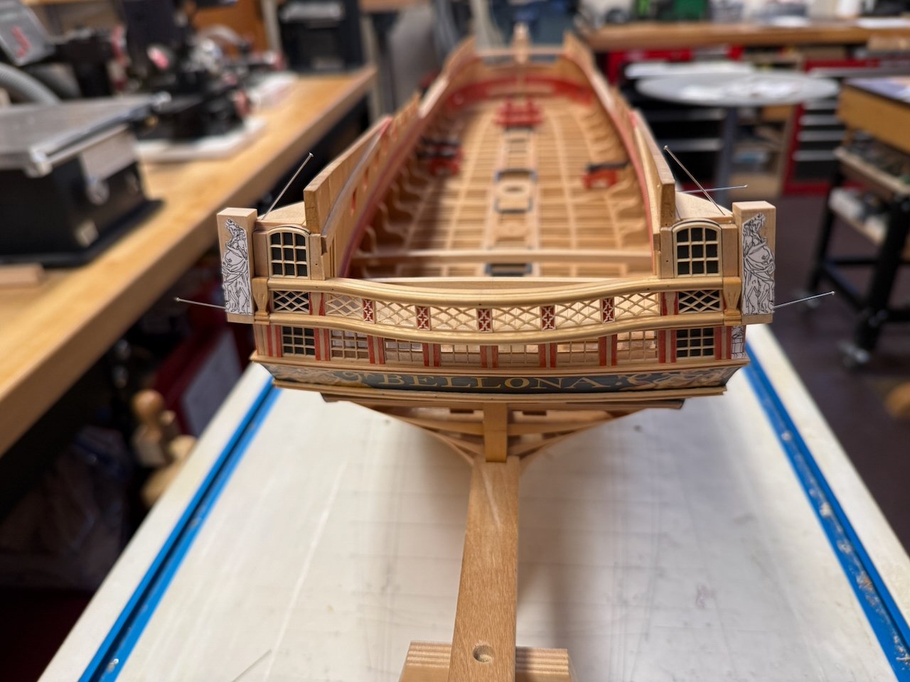
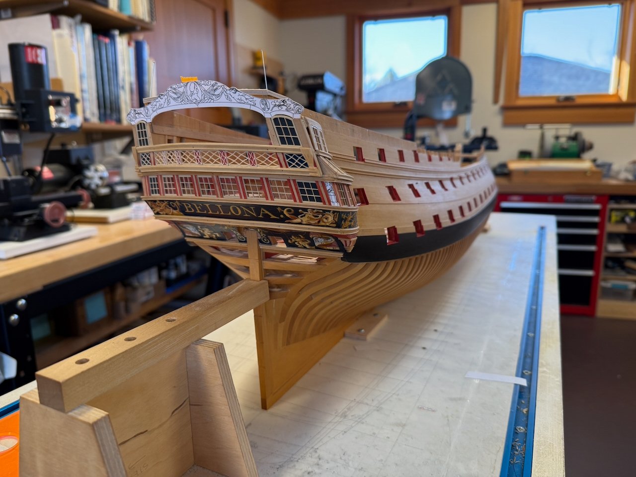
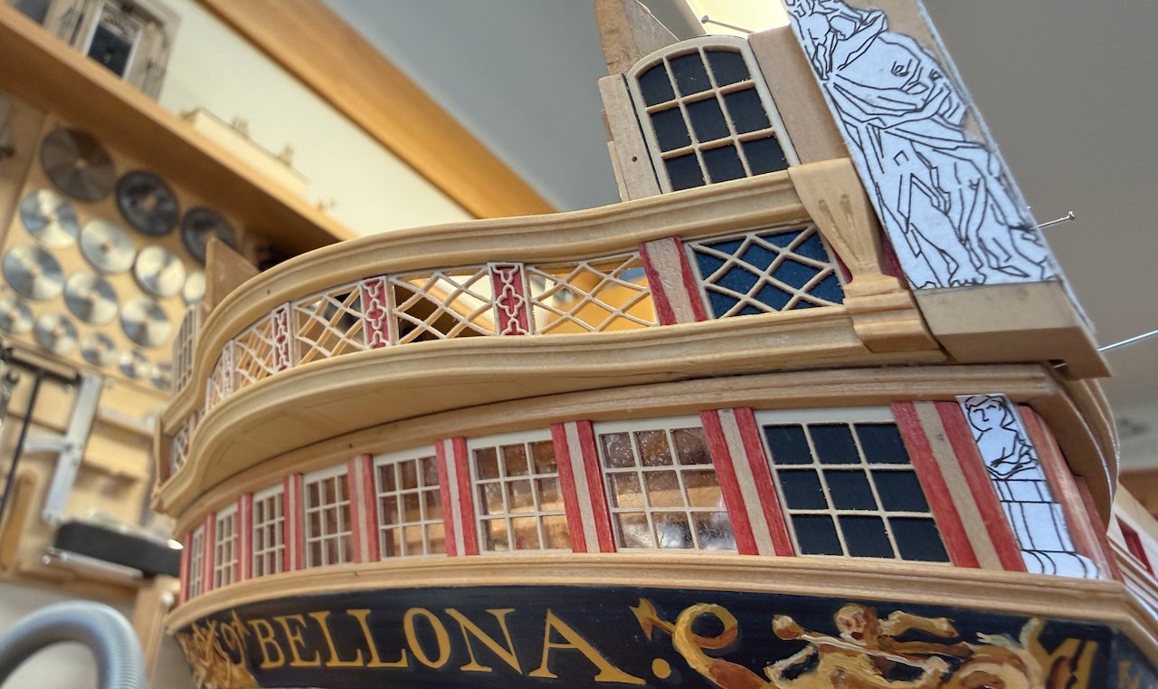
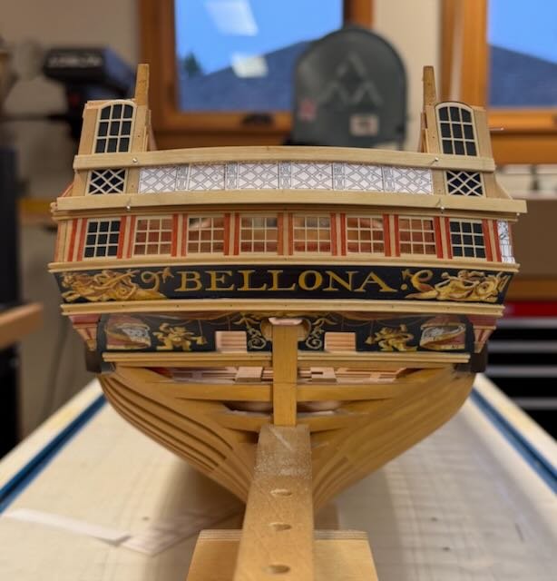
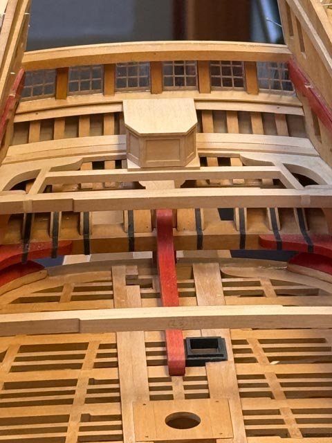
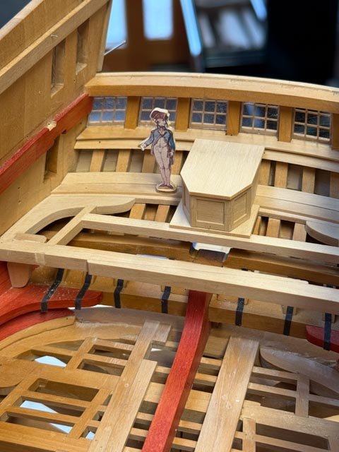
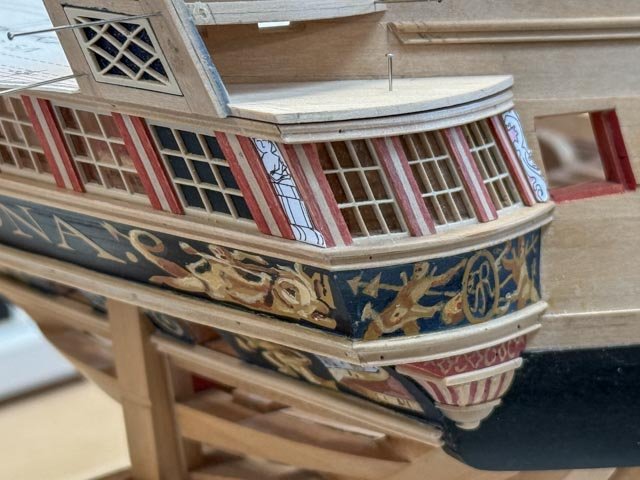
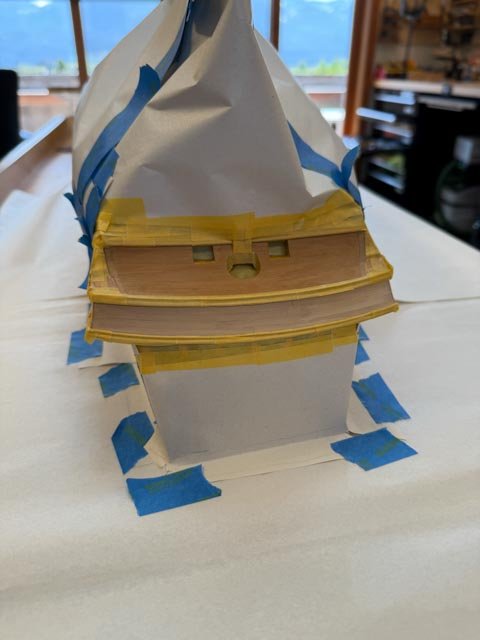
Hi Gary, thanks for the reminder. I have been so focused on a bunch of things that I forgot to post an update. The balcony is now in, and thanks again to Chuck for the outstanding laser cut fretwork. When I initially tried cutting these from boxwood, the wood basically crumbled. The resolution of the laser cutter exceeds the possibilities of wood construction, at least for me. And as Chuck pointed out, we have no doubt that the 18th century model builders would have used a laser cutter had it been available! Shaping the balcony rails was tedious. I had to make a former for each one (the upper one is shorter than the lower, with a different radius of curve). I tack glued the blanks to the former, and then carefully scraped the profile. Gluing the fretwork panels and filigree stanchion covers took some planning. I had to use superglue because I was gluing acrylic to acrylic. but superglue means getting the placement immediately right without room for error or a chance to adjust. A mistake would have been a disaster a this point. So after some experimentation I settled on super thin super glue, applied very sparingly with a loop tool to the joints. The glue then flowed in by capillary action and formed an invisible glue line. This method allowed me to tape pieces in place in advance, so their locations were already controlled. Many carvings are now needed in various places, but those will have to wait. I started making the last level of the quarter galleries, the faux shingles above the upper windows. But then I realized that I need the last row of planking on the hull, which in turn needs a moulding strip installed before the last plank. The faux shingles will also need to fair to the fore face of the taffarel, and so I will need to install at least the blank of the taffarel before proceeding with the shingles. The second to last image shows my beginning construction of the card pattern for this. I anticipate laminating the blank over a former of the appropriate curvature. Alan, I recall you were looking into the location of the stern screen wall in relation to the two doors to the quarter gallery. These images might help visualize how the parts go together. I couldn't really visualize it myself until I began to build it. It still remains a mystery why the captain needed a door to the quarter gallery from the exposed balcony deck, when there is another door just inside. Maybe he was shy when there were other people in his great cabin, and he stepped outside for "a breath of fresh air", then nipped into the quarter gallery.😉 And the third from the last image shows the small size of the quarter gallery as originally designed for the Bellona. Those are tight quarters! I am convinced the captain has a say when the Bellona refit 20 years later expanded the size.

-
Hi Alan, I'm glad it will help. After looking at a lot of advice on how to do this, I didn't trust my free-handing in a lot of the ideas. It took a little time to make the jig, but then you can crank out flawless beams every time, and very quickly. The only fiddly bit is measuring the actual angle of the top surface of each beam from a horizontal line (I did this from the plans) and then setting the jig angle accordingly. Also be sure to crank down the clamps; a beam blank slipping in the router table is a disaster. Also, be sure to mark each beam with its location and orientation; it is so easy to mix them up afterwards, particularly the ones closest to center where the slope is not as apparent. If you need any help or clarification, please don't hesitate to ask! Mark
-
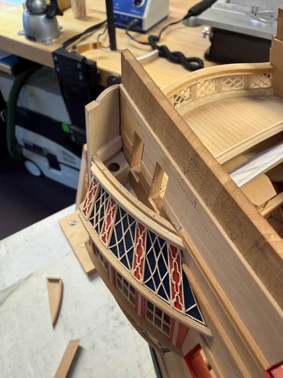
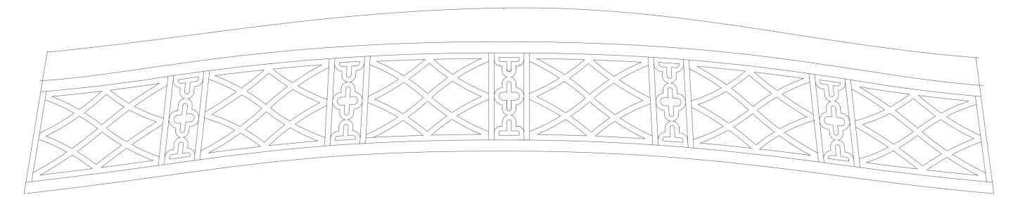
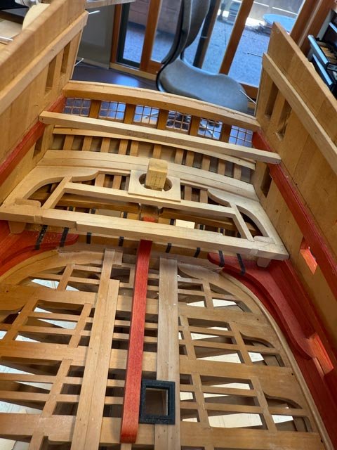
The Bellona balcony and corresponding quarter galleries are undoubtedly the most difficult things I have ever attempted to make! Progress is slow but moving along. To make accurate card patterns for the panels in the balcony, I first needed to construct the balcony moldings both at the level of the deck and the level of the railing. I had decided to capture the panels in rabbets, so I constructed the moldings in two parts (see below). The molding at the railing level will have a seam between the fore and after parts, and it will prominently show, so I needed to fair these two together as accurately as I could. To make it more interesting, the aft part runs all the way across the stern, while the fore part is trapped between the two sides of the hull. I pinned the aft one in place and then used graphite paper squeezed between the two to locate high spots. Trim and check, trim and check..... The fore piece also needed the rabbet in its lower outer edge, and a molding on the fore face. Here it is: With these pinned in place, I could then make up card patterns for the panels and the stanchions between. I made up small pieces of card that could fit firmly on the lower rabbet, and glue to the next card fitting firmly in the lower rabbet. With the lower curve firmly established, I could then trace the lines of the upper and lower moldings on the face of the card assemblage. You can see this in the second row first column below. I then scanned this and put it into my CAD program to trace and then draw in the detail. This proved to be surprisingly difficult. It seemed every time I drew one, glued it to card and installed it, the curves were wrong. Here is a selection of failures: I finally got one to work. The moldings top and bottom are still oversized and unmolded to keep them rigid until I can install the panels. Meanwhile, I finally painted the blue on the quarter galleries. Here we can see for the first time what the original Bellona ornament might have looked like on the quarter galleries. these are just resting in place, not yet glued down. So they are not entirely in place and not tightly pulled down to the underlying surfaces. But it shows what we are headed for. I give full credit to Chuck Passaro for this. He offered his laser cutting skills when I was bemoaning how I would ever make these, then he cut them beautifully, and then he pointed out in an earlier version that everything needed thinning down. What it looks like now is a great deal due to his skill and practiced eye. Thanks, Chuck! I now need to do some experiments with super gluing these together. I think the wide panels need to be glued at their edges into the red stanchions. And then the filigrees over the red stanchions need to be glued down onto the mating surfaces of the panels. I have to avoid at all costs any glue on the blue or red surfaces. But these parts are only .026 inches wide. I am going to experiment with 1) taping everything in place, then applying super thin glue for a capillary action into the joints; and then 2) thicker glue at a few spots along each edge, then eased into place. There is no room for failure at this point! Anyone has good advice on how to glue these, I am open!
-
Thanks so much, Cisco. I struggled a little to explain some of the issues, I am glad it eventually made sense. druxey, I wondered how you did your beautiful fretwork, and the answer of old school piercing and shaping is just as astonishing as the quality of the product! You continue to set the highest bar for us. Your work also points out that old school techniques could have accomplished the delicate filigree work on the second Bellona model. I wonder why they chose to render that detail as crudely as they did, when every other detail is highly refined and well crafted. The big holes in the white stanchion covers are not even accurately located and drilled. I cannot imagine that this detail was an effort to accurately represent the detail on the actual ship. Maybe they were running out of time on a deadline, maybe some original good details were damaged and later replaced later with this cruder version. A lot could have happened to that model in 240 years.
-
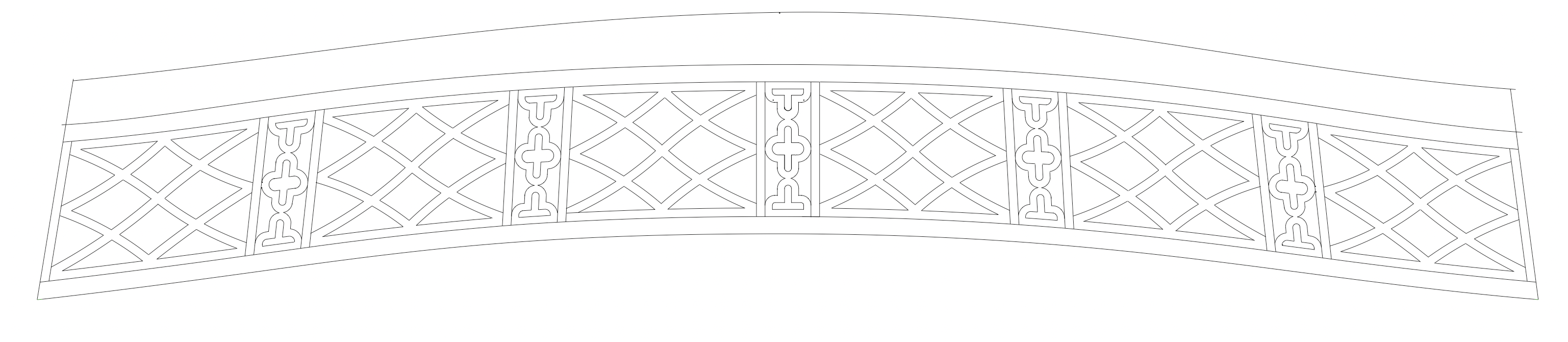
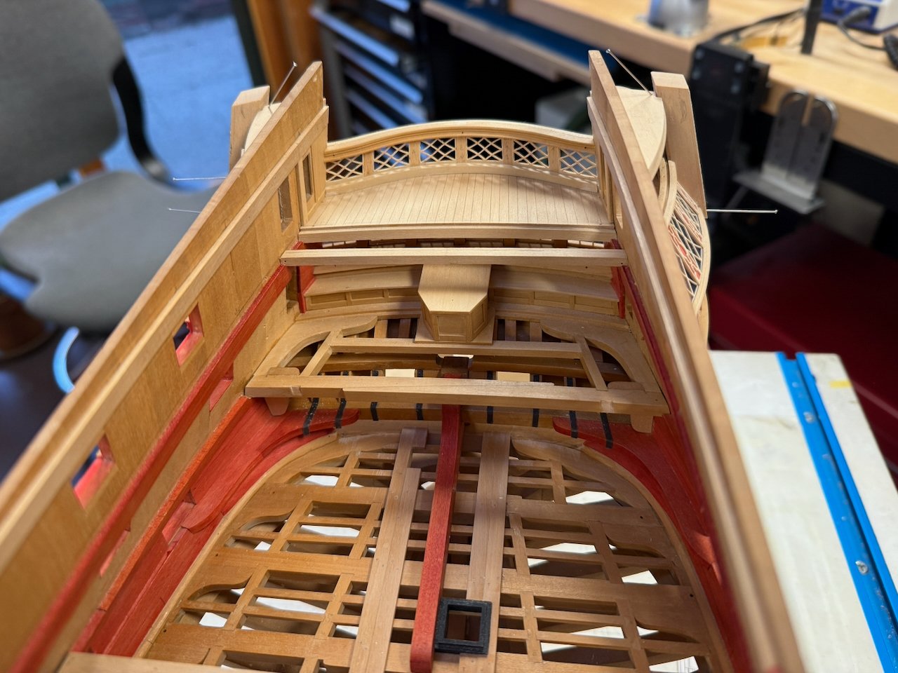
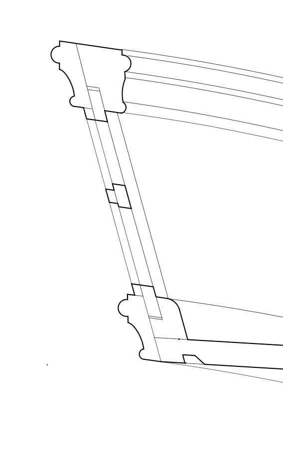
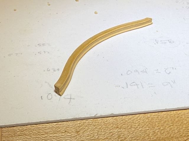
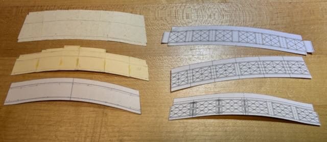
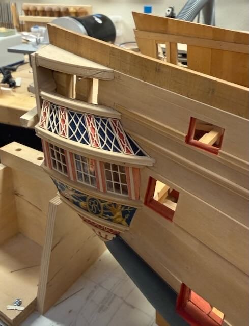
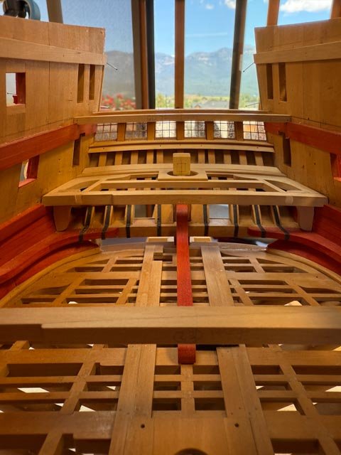
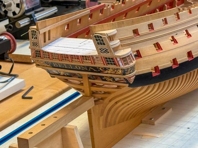
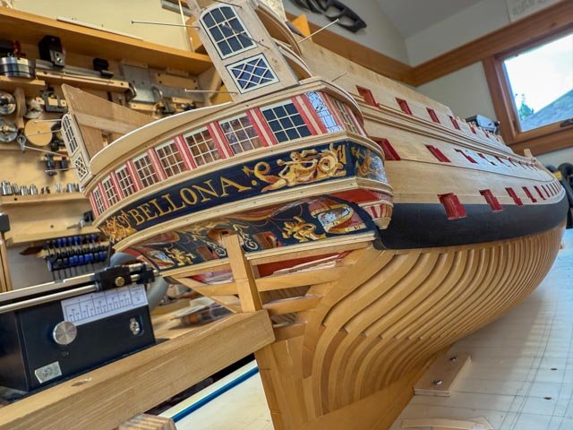
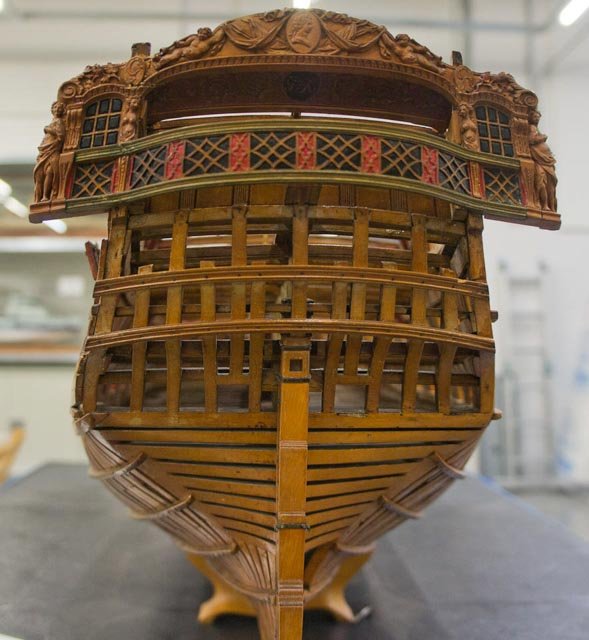
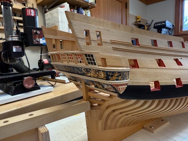
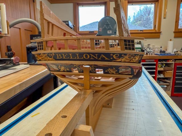
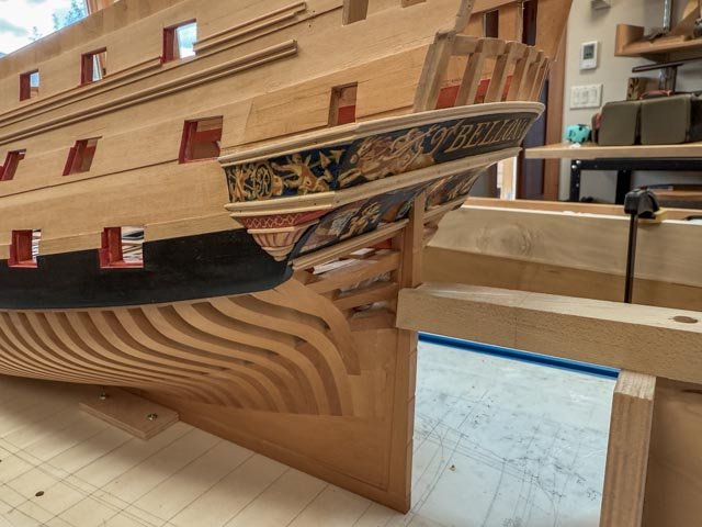
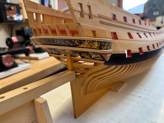
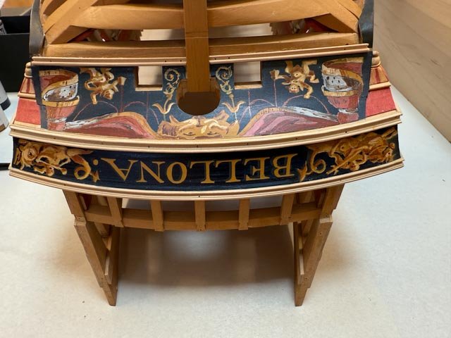
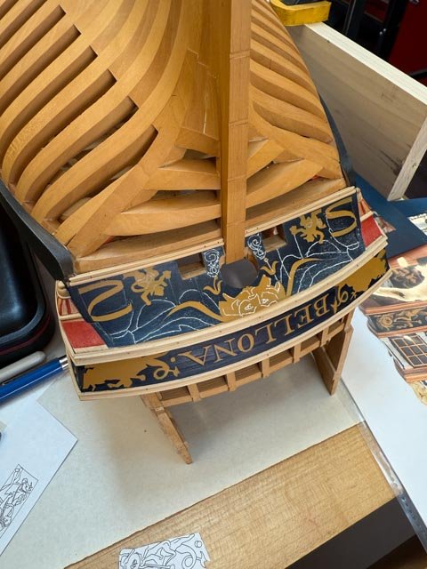
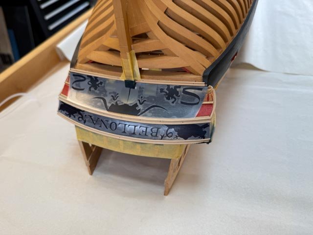
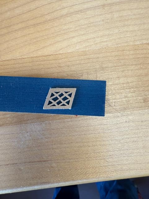
Time for an update, even though things are in flux. I have finally tackled the balcony and the fretwork on the quarter galleries that correspond to the fretwork in the balcony. First a bit of a re-visit on this detail that I knew was going to be the most challenging part of this build so far. In the images below I am showing the first Bellona model built ca. 1760 followed by the second Bellona model representing the ship after its major refit 20 years later. My project is reconstructing the Bellona as she was originally designed, as shown in the original admiralty drawings and in this first model. However, the first model did not show the quarter galleries, and so I have had to interpolate what the original quarter galleries might have looked like, related to the original balcony and then to the quarter galleries shown on the second model. So let's look at these more carefully to see what is the same and what is not. The original model shows a very distinctive fretwork on the face of the balcony, which we can assume was meant to be open as seen on the second model. The vertical stanchions in the original model are painted red, with a covering filigree subtly projected out forward of the fretwork within the rectangular panels. Note also that the first model balcony sweeps in a gorgeous serpentine curve from one side to the other. the second model, on the other hand, curves the balcony into a sharp corner one panel in from each side. It took me a long time also to realize that the first model is wider outboard of the outermost rectangular panels, with a more substantial bracket between the panel and the carved female figures. I saw the necessity of this extra width when I tried to reconcile the stern design with the original admiralty plans. The extra width was needed to make the quarter galleries big enough at their after ends. This then had a knock-on effect for the windows below. which also needed the extra width. You can see my interpretation of how this might have worked in the line drawing below, a little bust on a pedestal. Final thing to note before leaving the balcony. The original model has this beautiful filigree detail over the red stanchions. The second model did not even attempt to recreate this, choosing instead to drill crudely arranged holes in white panels. I had sympathy for their plight, attempting to cut these exceptionally fine filigrees. My own efforts at this failed spectacularly. Then I thought, I'll bet Chuck and his laser cutter can accomplish what the 18th century model builders had failed to do. Before looking at this in more detail, I'll turn to an overview of the quarter galleries themselves. Following are the quarter galleries on the second model. The model builder continued his scheme from the balcony, with stanchions represented as crude drilled holes in white panels. I decided in contrast that I would continue the first model scheme of fine filigree over red stanchions, keeping the dark blue paint behind the rectangular patterns. I drew up the quarter gallery pattern with this idea, and it is shown here as a colored pencil paper pattern: While working on this, I began to realize that this entire panel was a different shape compared to the one on the second model. You can see that the second model panels are much more rectangular with more upright sides, mine were turning out with more extreme sloping sides. And mine had a much stronger sweeping backward curve at the fore edge. What was going on? It took me some time finally to realize that the first Bellona model and admiralty drawings show a much smaller upper quarter gallery off the quarterdeck. Here is the original admiralty drawing immediately below. Note the more extremely curved forward edge of the panel between the lower and upper windows, needed to reconcile the larger windows below with the much smaller windows above. Compare this to the quarter galleries in the second model shown above; the windows above and below in the second model are almost the same size, needing a less extreme slope from the one to the other in the fretwork panel between them. I think we can assume that when the first captain saw that the quarter gallery of his brand new ship was substantially smaller than the one below shared by his officers, he strongly suggested that this would need to be rectified in any subsequent re-build! Pressing on, I worked up the drawings of the panels and sent them to Chuck, who returned the most beautiful fretwork panels and delicate filigree stanchion covers. I am showing them here loosely located; they still need to be glued down to the concave surface to pull them in more tightly. And I still need to paint the blue backgrounds behind the fretwork panels: These needed sanding down in thickness from the thinnest plastic Chuck could provide. I did this by trapping the plastic in a frame as thick as the final desired thickness, giving me a gauge for sanding down to the frame: Meanwhile, I started work on the balcony itself, so I can draw these final panels and stanchions for Chuck's laser magic. It frankly took a great deal of trial and error to craft the geometry of the serpentine curve. It needs to fair into the curved side panels and then reverse its curve twice. Also, the upper balcony railing is narrower in athwartship width but still needs to slope back enough in its narrower space to maintain at the center of the balcony the backward slope of the side panels. I could not visualize how this would work. I tried carving a blank out of basswood, which helped, and then built a card blank multiple times to keep refining the curves until they seemed right. Then I worked out the actual geometry in plan: This gave me the patterns for roughing out the lower and upper moldings, shown here. the blocks are spacers to keep the two moldings parallel to each other while I refine their fit against the side panels. These are still much oversized, until I get all of the parts to talk to each other handsomely. I intend to trap the laser cut fretwork in rabbets as shown here: I now need to create an accurate pattern of the shape between the two railings, to draw the fretwork and filigrees for Chuck. The saga continues! Mark


-
Oops, sorry, I forgot to thank JD and Mike for their encouraging comments. JD, I am getting closer to cutting into that boxwood for the sculptures on the stern. Just want to get past the decorations on the quarter galleries and the balcony....
-
Thank you, Frank, for your kind comment. And druxey, I think the removable or hinged rudder cover is an interesting idea. It would be way easier than removing the entire cover, and a tackle rigged over the rudder head could pull straight up. Regarding the model not the real ship, I found it most convenient to construct the rudder cover as one unit, to keep things square and shipshape. The five sides would have been difficult to keep in alignment to each other without the top as a guide. So my entire unit will have to slide out now that I have the beginnings of a quarterdeck above that will prevent pulling straight up. I notice that in Rob Napier's Legacy of a Ship Model, pp. 83-85, he and David Antscherl speculated on a similar problem in the Princess Royal model, with a rudder cover struggling to accommodate shipping a rudder once the cover had been installed in the model. Always fun to see how our 18th century predecessors sometimes struggled with the same things we struggle with!
-
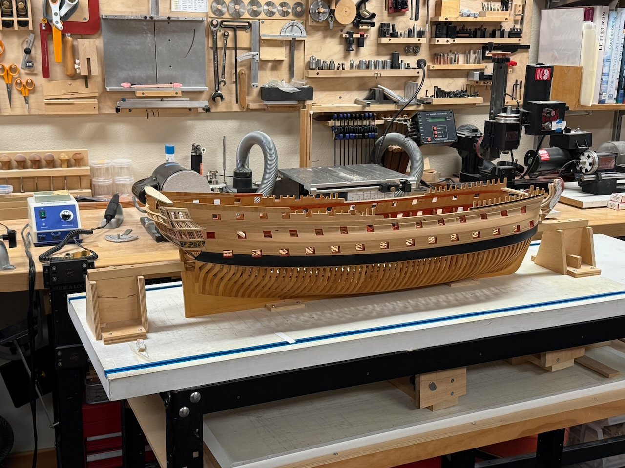
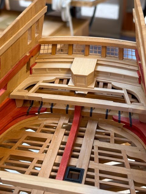
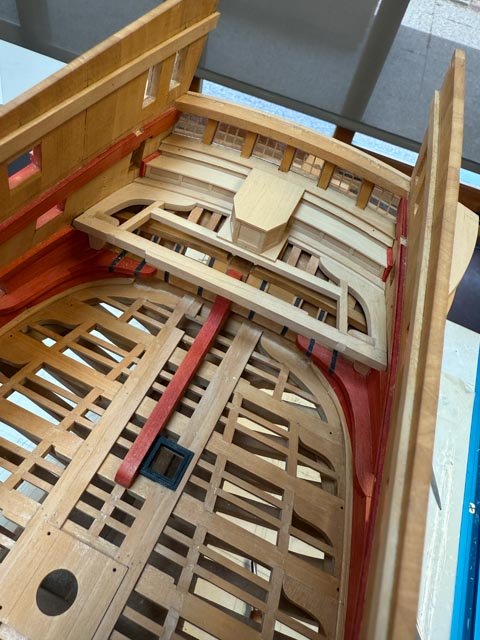
My main goal now is to construct the stern balcony enough to get drawings to Chuck for the fretwork. But before that I have to build a stub deck at the end of the quarterdeck. But before I can do that, I had to build the stern of the upper deck with the rudder cover and benches, since they will be covered up once I install the stub deck above. And before I could build the rudder cover, I needed to mock up the rudder head to ensure it will turn freely in the rudder cover. And on it goes..... So, here is the mocked up rudder head, checking clearances: And then the rudder cover itself. Note in the first photo, I somehow built it too wide. The second photo below shows the trimmed down version. I had to selectively deconstruct the cover, then slice out the excess, and reassemble. It reminded me of chopping tops for hot rod models when I was a kid! I discovered that if the rudder cover top surface stays below the level of the stern lights, there is not enough room under it to ship the rudder. It will have to be removed and then reinstalled after the rudder is in place. So when I built the benches on either side, I made all of this a slide fit so the rudder cover can be taken out later to ship the rudder when I get around to building it. The benches proved to be unexpectedly difficult to build. They had to accommodate different curves at different levels, since this is all sitting on the fore side of a convex upper counter whose curves are different from the upper deck upon which the benches sit. It was a lot of tedious trim and test, trim and test, for several days. But now it is done, ready to be covered up by the quarterdeck stub deck above. At least I could get some sense of the standard of living for the officers. Not bad, sitting on the bench, elbow on the window sill, looking out at the sea through the wall of windows.... Mark
-
druxey, scrubby, Albert, Chuck and Marc, thanks so much for your kind comments. I am feeling so slow on progress these days, even though I am working at it pretty diligently. It really helps keep me going to get these great notes of appreciation from all of you! I cannot sing the praises of Chuck's work enough. Working with exceptionally tight tolerances, his window frames fit like a glove. The filigree work above is going to be an even greater exercise in close tolerances, and I am still working on how to captures these in rabbets strong enough to hold against a surface curved in two directions. I'll post some drawings when I get a little close to a final idea. And I continue to be amazed at the design of the Bellona in all of its detail. Those guys really knew what they were doing! Mark
-
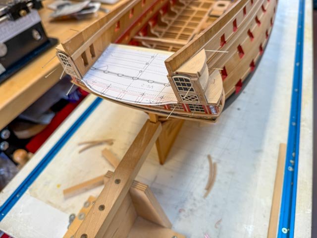
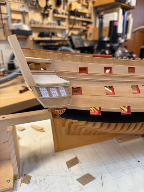
A quick update. I finally installed all of the upper deck lights, with the red cover plates holding them in place with the help of a little LockTite Extreme glue. This was necessary for bonding the plastic window frames to the wood, giving a few minutes repositioning time to settle everything in the right location. I had considered using superglue, but it has no leeway with repositioning time. I placed mica behind the frames for the glass. It was easy to cut, and as thin as the windows ought to be in scale, greatly facilitating the construction details. Chuck's laser cut window frames look fantastic! Thanks so much, Chuck. I still have to construct the architectural columns in the centers of the red cover plates, and I am showing here some paper placeholders for later carvings. But I have decided to move onto the balcony for now, which will probably be the most challenging part of this build. It has open fretwork between stantions, and the whole thing is a serpentine curve, as seen in the original 1760 model (here the fretwork is carved out of a solid blank; they are open in the second model which I assume is the intention of the model shown here). Mark Chuck already laser cut the fretwork for the side panels, as seen best in the last photo below the curved top window. This again shows the beauty and delicacy of Chuck's work. this same pattern will hopefully run across the balcony, and then around the quarter galleries at the same level.
-
Thanks so much, everyone. This was a major hurdle for me, thinking about it for many years, and now able to move forward. A couple more thoughts, for those working on paintings like this. 1. Using frisk to lay down the base yellow ochre actually accomplished a couple of things. Not only did it allow a smooth application of airbrush paint, but it also solved part of the problem of getting the design transferred to the hull. Because the frisk is based on an accurate drawing, there is no need to worry about sketching in the design on the model itself, trying to keep faithful to proportions and sizes. It is as accurate as the drawing used to cut the frisk. 2. To get an accurate underlying drawing, I scanned photos of the painting on the original Bellona model, and imported them into my CAD software (HighDesign 9 for Mac). I then resized them to approximately the correct sizes and printed them. When I cut out each print and laid it onto the hull, I could see where the shape needed to be adjusted for more or less curve, a little wider or narrower. I would then make these adjustments to the CAD drawing, print again, adjust and so on until the CAD drawing was an accurate fit. Then I knew the frisk would fit well in its assigned space. 3. Regarding airbrush paint, I also started with Vallejo, which is highly regarded by many modelers online. But I also had problems with these clogging my airbrush (Harder and Steenbeck Evolution). Although I tried a number of suggestions for thinners seen on YouTube videos, nothing seemed to work reliably for me. It may be that I did not work out a good way of mixing the paint and thinner, or it may be that spraying on wood rather than plastic makes a difference. Golden High Flow paints worked without thinning, which does allow for a greater consistency in what is going to happen when you pull the trigger. And they match the Golden Fluid acrylics for hand painting. 4. As David Antscherl pointed out in his section on painting in the Fully Framed Model, the base layer of yellow ochre is a translucent paint, not opaque. So when spraying or hand brushing yellow over Prussian blue, the resulting color goes green. David's advice of mixing some white into the yellow ochre for hand brushing helps, while a number of layers of airbrushed yellow ochre eventually goes opaque. They dry so quickly that it is possible to get an opaque finish in one session of airbrushing. I look back and wonder why it took me so long to work out this painting business; and now I remember the many experiments, dead ends, different products.... Mark
-
HI everyone, A long time since my last post. I realized that I was getting to far ahead of myself, building up the stern with everything just pinned. I needed first to paint the lower and upper counters before I could actually start assembling things. And learning how to paint the friezes was a major learning curve! I greatly followed David Antscherl's advice on painting in the Fully Frame Model, vol. II section 7.26. It was exceptionally helpful for everything from paint and brushes to technique. Alas, I discovered after a great deal of experimentation that hand painting alone did not work well for me. Particularly for the background Prussian blue and the letters "Bellona" on the stern, I needed a way to get things sharper and more even in tone. So, I turned to my airbrush. I masked everything but the counter and sprayed away. I glued artist's frisk onto a print of the upper counter letters and frieze elements (a woman riding a sea monster, a man riding a galloping horse). I could then turn the frisk/print every which way on my light table, and very carefully cut the frisk with a scalpel. I then attached the frisk and sprayed everything that would be the yellow ochre base for all of the frieze work: I then used white graphite transfer paper to trace the rest of the pattern onto the surfaces: Then following David's advice of painting highlights and shadows on the basic forms, I eventually got to an imperfect copy of the original Bellona model: I learned to admire those original model builders for their painting skill. Try as I might, I just could not get to the same level of skill. But as good as I can do! So, moving on to actually gluing together the stern! I did learn a few good things that I will pass on for anyone else attempting these kinds of friezes. First, after trying a number of airbrush and hand paint brands, I settled on Golden. They have the same colors in different densities, for airbrushing and hand painting; the colors match the historic colors I was looking for; they come in plastic bottles with ball bearing inside, for mixing. They spray without problems through my airbrush. And they are highly regarded in the artist community. Second, I struggled with the acrylic paint drying too quickly on the palette when I was trying to mix colors. My son introduced me to the model gamers' favorite tool, the Army Painter Wet Palette. This tray holds a water saturated pad, upon which is placed a parchment sheet. Paint mixed on top of the parchment can stay wet and mixable for as long as 48 hours. A huge help! A glass of wine tonight in celebration, and on to assembling the stern! Mark
-
Hi everyone, Sorry for the long silence; other things going on! To catch up. First, Der Boss, thank you for your kind comments. Slow and careful keeps me moving along! Trevor, thanks for the reference to Roberts. I haven't seen that, but I do have the facsimile book and set of plates for Steel's Naval Architecture. I have used that to help with several questions of drafting, but could find nothing on the curved surface between the upper deck and quarter deck windows on the quarter galleries. And Gary, good to hear from you! We old timers go back a long way on our 74s! And druxey, thank you for your list of tools and materials you used. I did a little test fret-sawing boxwood, and if I find myself going down the route of fret sawing, I have determined that wood is too crude for the very thin cross grain pieces (see below). I can see plastic would be a much better material, no grain to deal with. And once I saw that plastic might be the right material, I mocked up the curved surface in basswood to see just how sharp the compound curves would be. This would be to test whether glue would be enough to hold flat plastic against the curved surface. And the surface turned out to be less curved than I thought. The front edge sweeps back at a good angle, but at any line drawn between the upper and lower moldings, the surface curve is gentle. So for now, I will explore having these laser cut. I first need to reinstall everything with the final windows (coming from Chuck, thanks so much!), and then carve the final curved surface to measure and expand for a true elevation of the fretwork. Mark

-
Thanks, everyone, for your comments. Kevin, intriguing idea about 3-D printing, but I don't think I have the skill to work up a 3-D drawing of the double curved quarter gallery surface. It is no known regular geometrical shape, and would have to be built up in sections and faired like a hull. I may come back to this if I can't figure anything else out. And thanks for reminding me of Marc's fabrication techniques. Marc, thanks for thinking about this. Your techniques could well provide a way to build these forms up, rather than attempting to pierce saw them out as a whole. My first experiments showed me some problems with attempting to cut these out of boxwood--grain runs across some of the thin pieces, doesn't have any flexibility--and so I may have to explore other materials if I go down this route. Or, maybe I just make up individual strands with the grain running the length of the piece, and then glue them together at the intersections. This would be more like a mesh that could settle onto the curved form behind, because it could slightly bend at each joint. druxey, I greatly admire your fretwork on the Polyphemus. That is exactly the same kind of fine delicacy of inter-weaving lines that I need to produce. And your's is flawless! Did you fret saw those out of boxwood as individual strands, or pierce-sawed some of them as panels? Sailor, thank you for your kind thoughts. I admit that this challenge slammed on the brakes for a bit, but I remind myself that I have always found a way forward when this happened in the past, particularly with help from this forum. And Greg, like you, I sometimes reflect on the astonishing skill of the 17th and 18th century model builders, especially given their technological limitations relative to our age. Like the old saying about Ginger Rogers--that she did everything Fred Astair did, but backwards and in high heels--the original model builders often did more with less than we have. One can hardly believe humans are capable of such fine work. I also find myself sometimes channeling the original shipwrights, when I am fashioning a piece and realize that a number of people did exactly this same thing two to three centuries ago. What a great hobby. Mark