schooner
-
Posts
741 -
Joined
-
Last visited
Content Type
Profiles
Forums
Gallery
Events
Everything posted by schooner
-
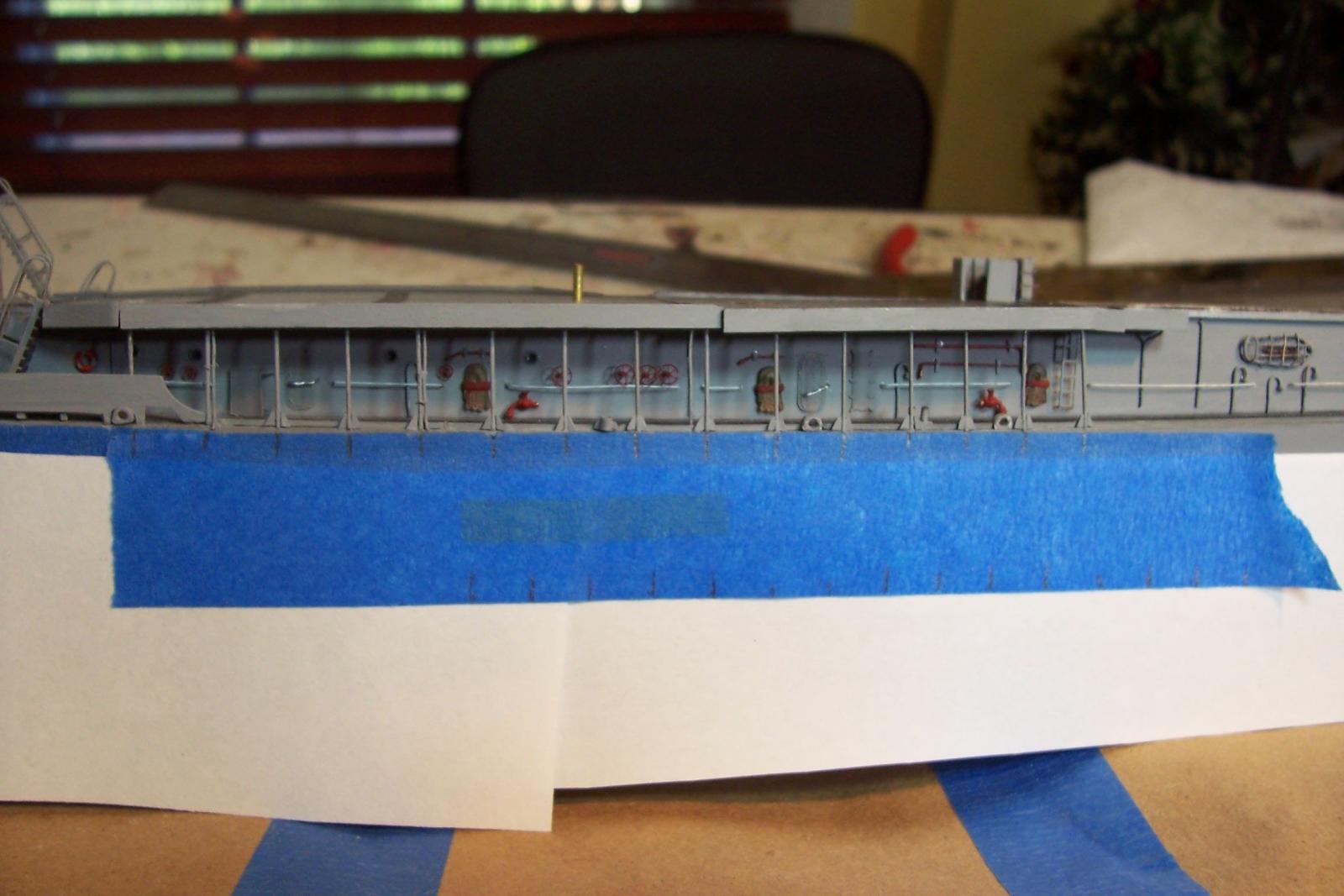
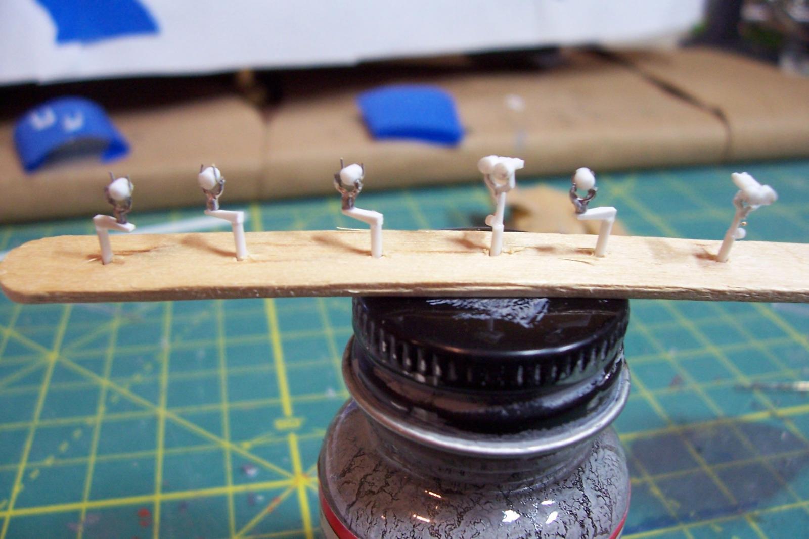
 Main deck stanchions One of the unique visual markers of the FRAMs was the widespread use of rather spindly deck stanchions between the main deck and 01 level. USN cruisers and destroyers of the 50’s to 80’s all had a least a few but none as many as the FRAMs. Deck stanchions have pretty much disappeared in more modern ships in an attempt to be more stealthy by eliminating such radar-reflection highpoints. The stanchions are .020 wire per the kit instructions. My only additions are the deck drain pipes and gussets on the after groups. Next up will be detailing the forward 01 level deck.
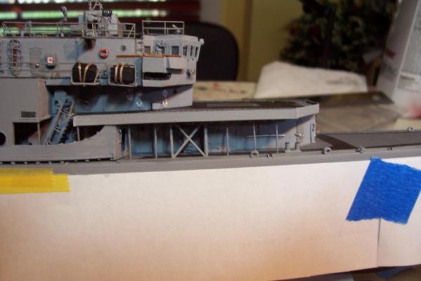

- 144 replies
-
- 7
-

-
- basilone
- BlueJacket Shipcrafters
- (and 2 more)
-
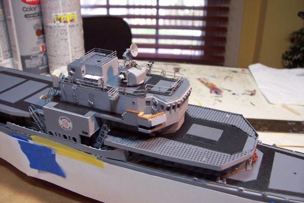
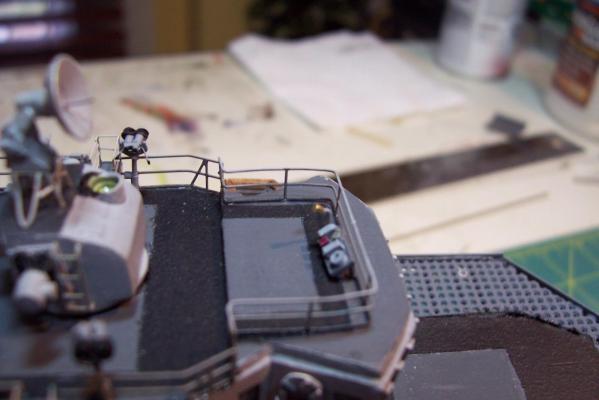
Bridge level details The kit provides pelorus’ for the bridge wings, they look good but when fitted on the model they are too tall (6 ft at scale). Although it would have been a simple matter to trim them by 3/32 or so I happened to have some smaller ones from Bluejacket in my spare parts kit that fit just fine. Here’s the finished bridge level. Kit provided items include the deck gratings, vertical ladders, railings and the 2 lockers on the port side. The WTD's (without windows) are aftermarket, everything else is scatch made. Next job will be installing the stanchions that run between the main deck and the 01 level.


- 144 replies
-
- 8
-
-
- basilone
- BlueJacket Shipcrafters
- (and 2 more)
-
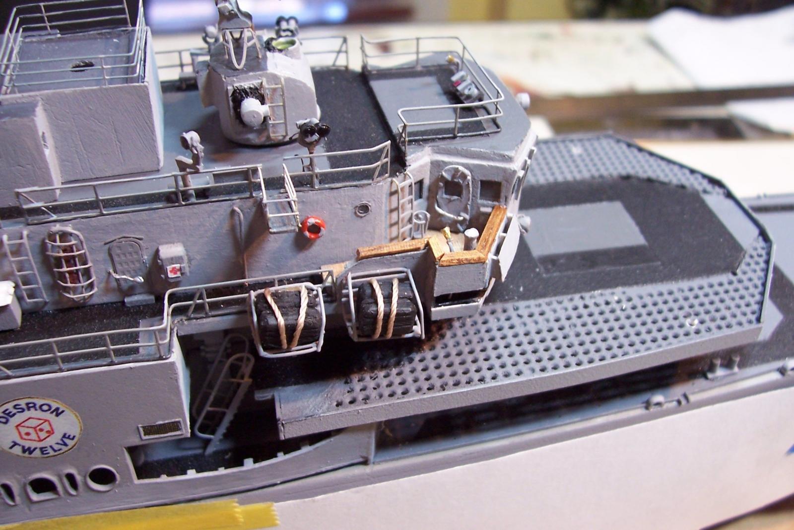
Bitts & Chocks The kit provides closed chocks and 2 sizes of bitts, all nicely done in Brittania metal. The sockets on the deck edges for the portable davits are scratched. Signal Bridge detailing I bought some 12” signal lights from HR Products, and while they look good from the front, when viewed from the top or side the lights have no depth, they are almost flat. I cut out the lights leaving the yokes and cut plastic rod to size, flat on the front face and curved on the rear, added a dog-leg arm so the light can signal ships astern, and the shutter arms. I also scratched 2 “Big Eye” binoculars. Here’s the finished signal bridge. As I mentioned previously, the Ops Office/Signal shack is scratched since on the Basilone and the other FRAMs modified at the Philly Navy Yard the structure is significantly larger than on other ships. The Sig shack is dry fitted and will be glued down when I step the mast. The pyro lockers, sound powered phone boxes, and the unusual knee-high instrument panel that constitutes the flying bridge, and its voice tube are also scratch additions. Next up will be detailing the bridge level.


- 144 replies
-
- 6
-
-
- basilone
- BlueJacket Shipcrafters
- (and 2 more)
-
Hi Hekk, Good choice for a starter kit. I built, in order, Midwest's Chesapeake Flattie, Whitehall Tender, and Skipjack. The directions on each were great teaching aids, showing you not just what to do but HOW to do it. By the time I finished those 3 kits I had the confidence and skills to tackle a POB sailing ship. Needless to say this stuff can get addictive. Good luck with your build.
-
Amidships Bulwarks Re-Do There’s nothing like a photo (however bad) to bring out the flaws in a model. After looking at the pix I posted something was really bugging me about them - the gap I created at the bottom of the bulwark, while to scale at 12”, was simply too big. Fortunately the thickness of the bulwark is a standard size for plastic strips so after a little reconstructive surgery I was able to reduce the gap to what I was after in the first place. One step forward - One step back...


- 144 replies
-
- 7
-
-
- basilone
- BlueJacket Shipcrafters
- (and 2 more)
-
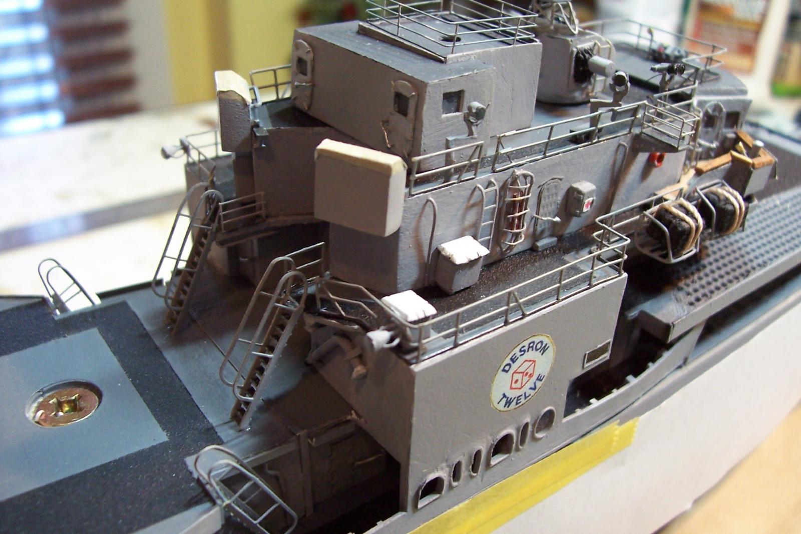
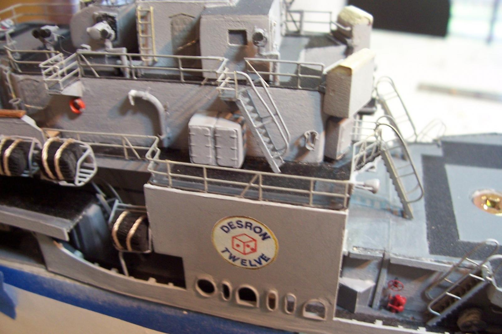
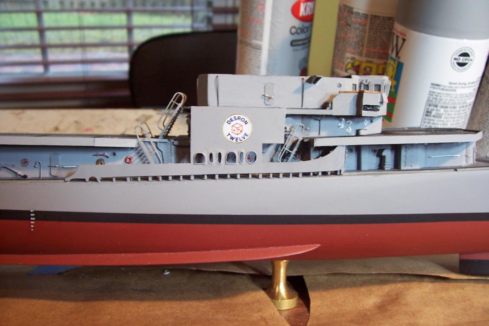
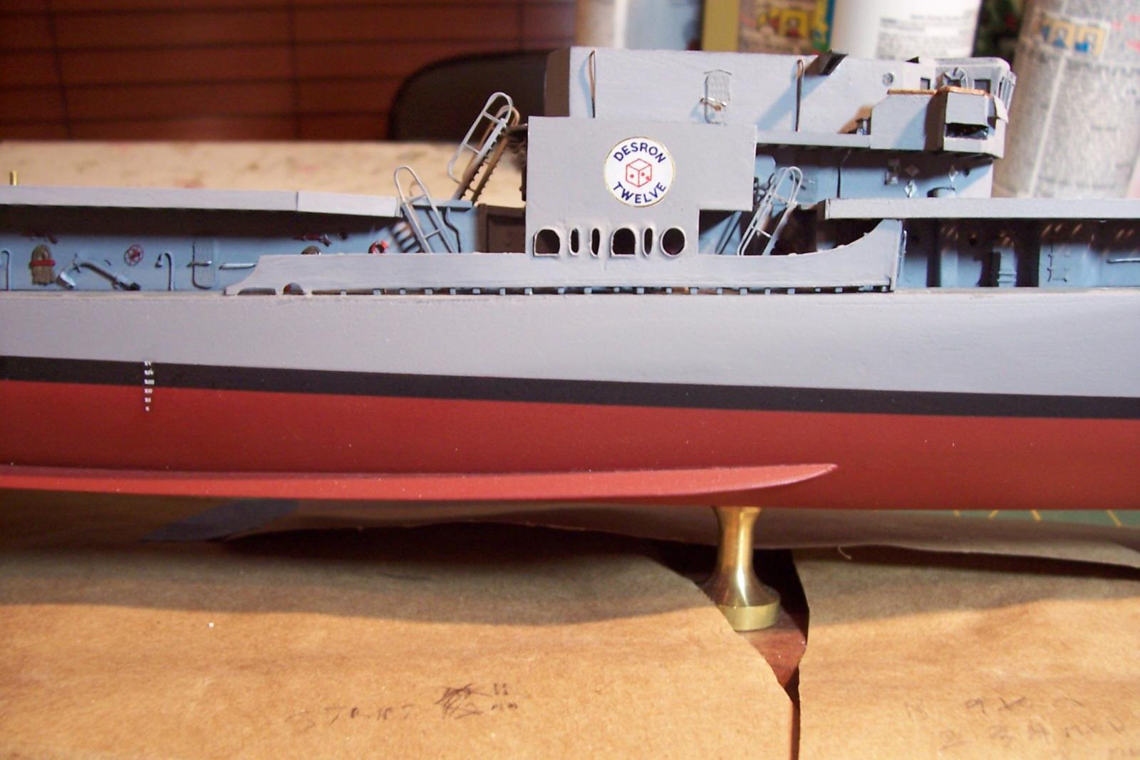
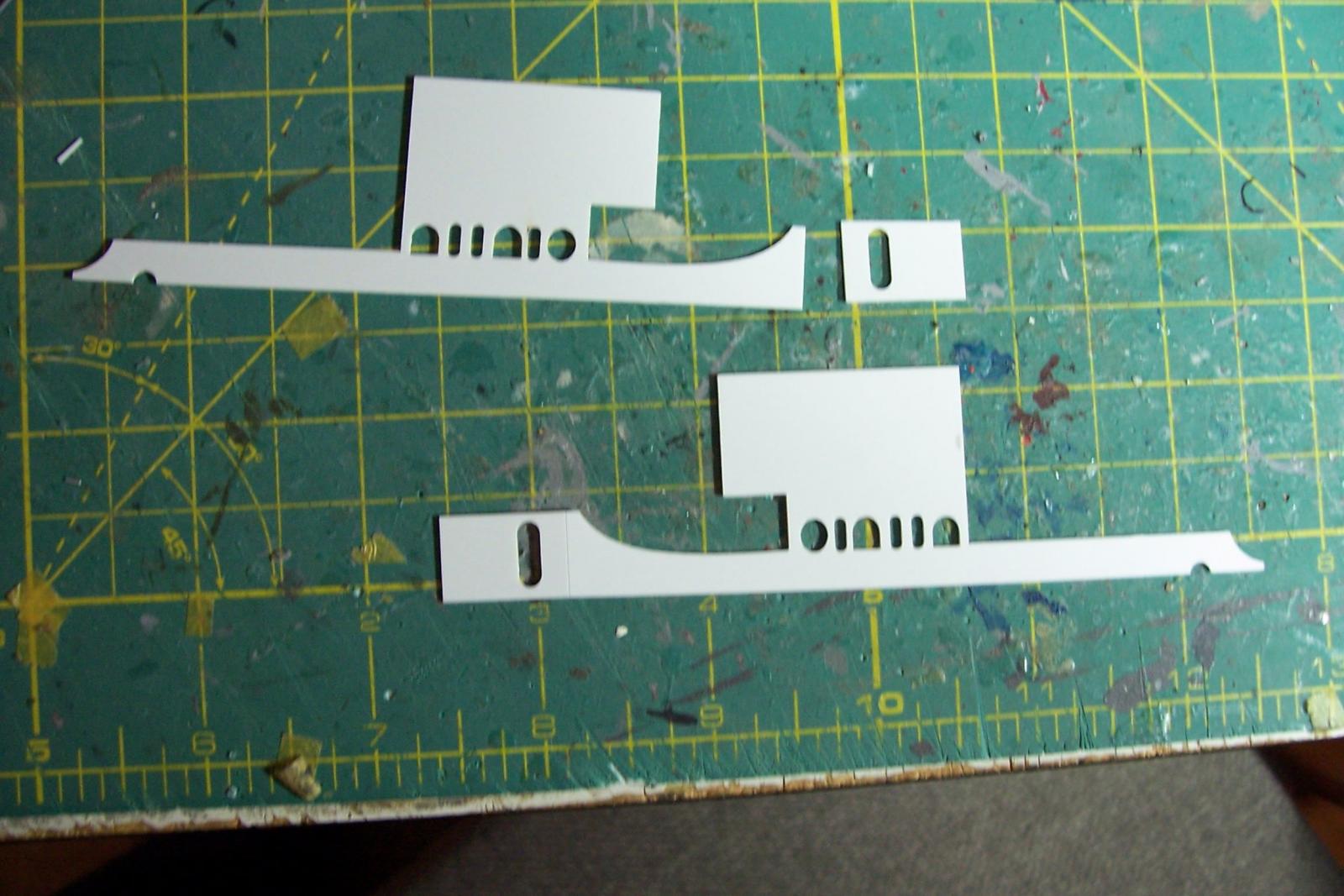
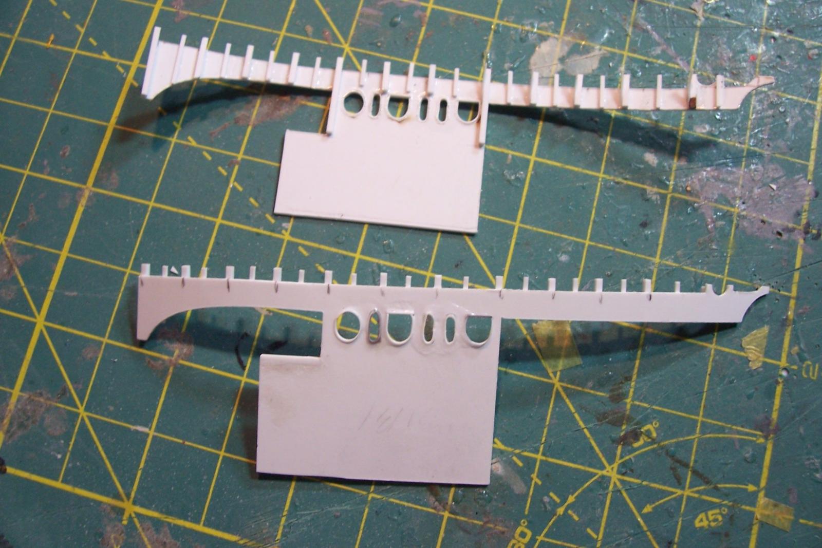
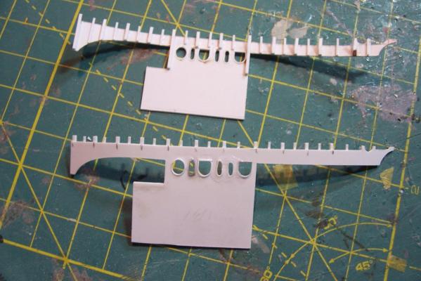
Amidships Bulwarks One of the distinguishing features of the Gearings was there prominent bulwarks with 6 varied openings of circles, ovals and arches. Although during the FRAM modernizations the superstructures were completely removed the bulwarks were rebuilt the same as before - one of the few points of continuity from their pre-modernization appearance. The kit provides the bulwarks as a single piece of laser cut sheet plastic with a thin section were a bend occurs. One of mine broke at that point but it was just as well, with so many points of contact it would have been difficult to fit it without breaking it down into pieces. It also worked out OK because the door cutout was too big for the PE frame I wanted to use so I made new pieces with slightly smaller door openings. The first modification, although the kit instructions don’t mention it, the kit plans clearly show that the bottom of the bulwarks do not rest flush on the deck but are supported by the bottom of the interior stiffeners. I cut off 1/16 inch from the bottom, added stiffeners to the inside face and angle braces for the aft section (the rest would not be visible). The other modification was to line each opening with support bracing. After painting and fitting the bulwarks I printed out the emblems for DESRON TWELVE which BASILONE was assigned to in 1966 in Newport. I got the design for the emblems from a former BASILONE sailor. This small step took an extra trip to the hobby shop since I didn’t think about the fact that printers don’t print white, so back I went to get white decal paper. Next step will be to add the chocks and bollards to the main deck.


- 144 replies
-
- 6
-
-
- basilone
- BlueJacket Shipcrafters
- (and 2 more)
-
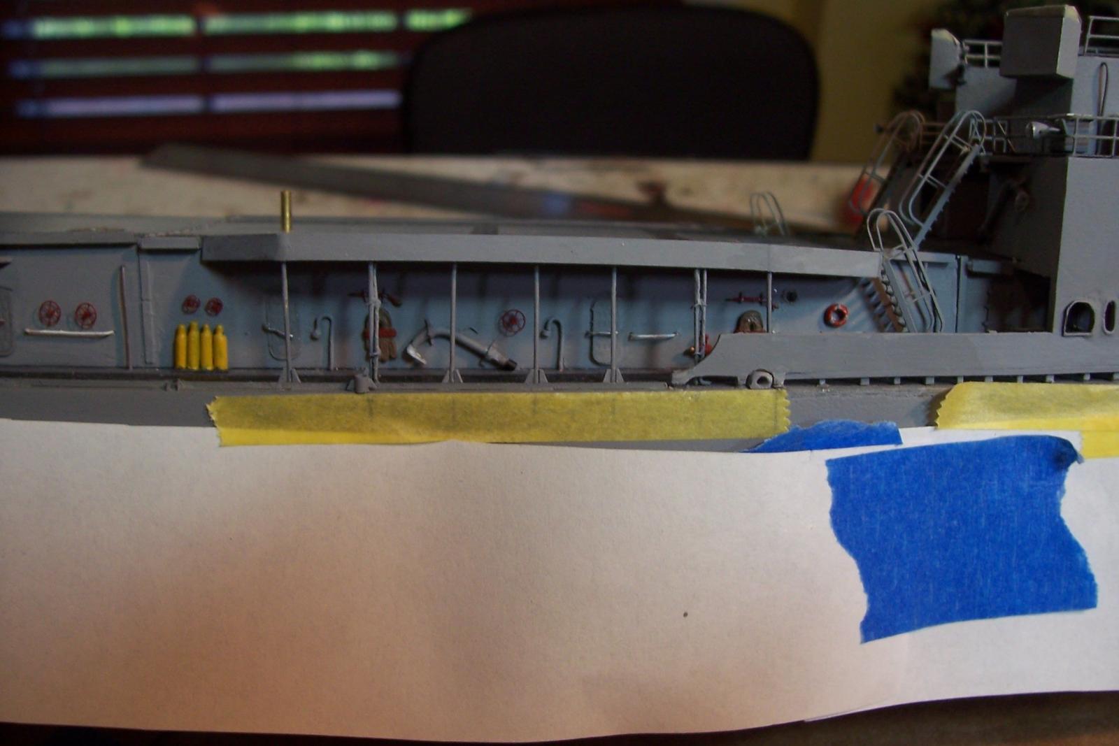
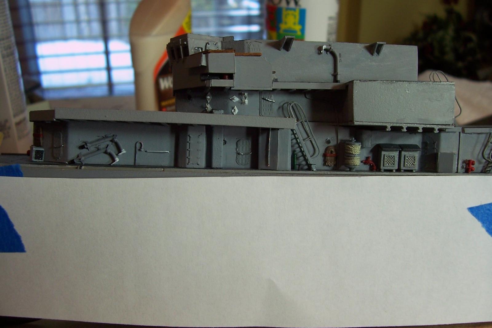
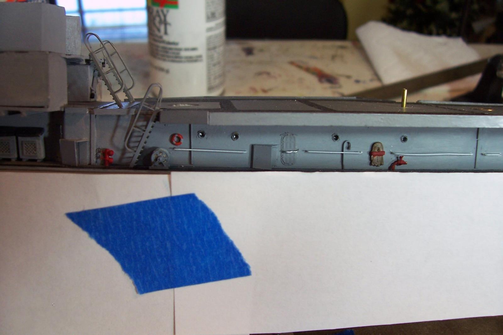
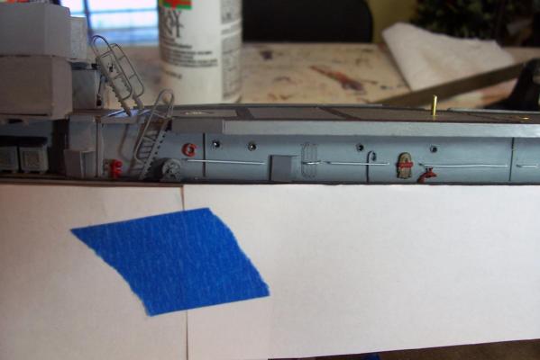
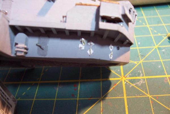
Main Deck Bulkhead details Have been slowly adding small details to the bulkheads on the main deck level. I covered the watertight doors in a previous post. Kit-provided additions since then include vegetable lockers. ladders, large line reel, and grab rails. Aftermarket PE additions include the porthole rims, the hand wheels on the deck (must have been real shin breakers at night), and small line reel. Scratch additions include deck drains, gooseneck vents for fuel tanks, water diverters, vent outlets, fog gong and locker on aft bulkhead, life rings, and oxygen bottles. Still to go are the remote operated valve hand wheels and firefighting equipment. The ugly vertical surface with the exposed I-beam ends will be covered up with a bulwark shortly.


- 144 replies
-
- 8
-
-
- basilone
- BlueJacket Shipcrafters
- (and 2 more)
-
Hey Steven, I'm glad to see a build log of this kit, it has been on my radar for a while but I have not been able to find any build logs of it that went beyond the hull so I hope you make it to the finish line. Given your boatbuilding skills you should do well this this. Good luck Tim
-
Hey Pat, I just came across your log. Great looking ship, can't beat an all gun destroyer. Glad to see another steel-hull build underway. I'm really looking forward to watching you detail her. I've been having fun doing that on my Basilone build but at 1/192 it's quite a bit easier than 1/350. On the other hand there are a ton of after market PE and decal options available to you at 1/350, much more than at 1/192. I've built a few small resin kits. Pin holes and voids are just part of the fun, yours doesn't look too bad compared to other manufacturer's. Before you get to the stage of painting stuff I hope you are aware that resin parts have to be cleaned first or the paint will not stick. Some kits just need warm water and soap, others need commercial silicone remover. You may want to experiment on some scrap pieces before you go big on painting. If you have not checked them out, L'Arsenal has a lot of 1/350 resin and PE details that might come in handy, that said the upgrade kit for your model looks really sweet so you may not need to go anywhere else. Good luck and have fun Tim
-
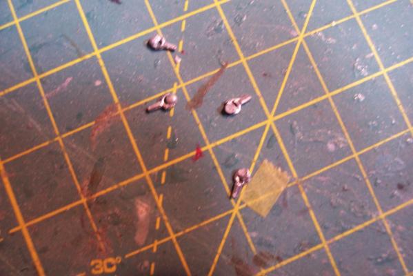
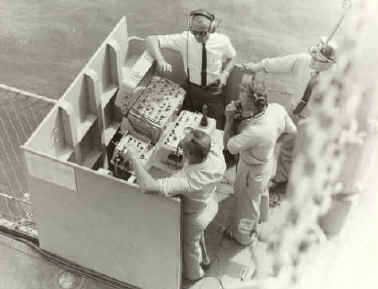
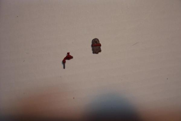
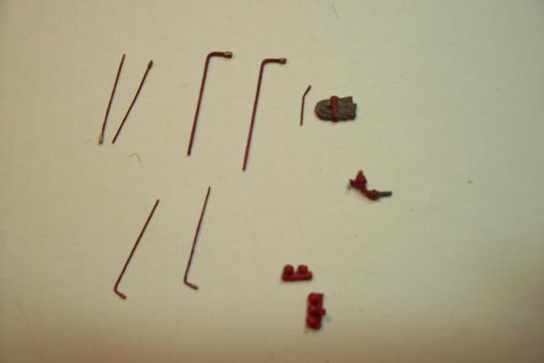
DASH Control Station THe DASH Drone was controlled from an open air cubicle on the forward edge of the flight deck. It was basically a desk with a little protection in case the drone got too close. All the control electronics were in portable suitcases so the station was minimally equiped. Here’s what I came up with (the cable cabinet is scratched based on photos): Portable J-davits Simple davits were stored around the weather decks and used for such things as rigging the accommodation ladder and lifting heavy objects from boats alongside, between decks and even up through the large foclse and fantail hatches: I scratched some out of wire, styrene and paper for the mounting brackets. When not in use they were usually stowed in brackets on a bulkhead:


- 144 replies
-
- 5
-
-
- basilone
- BlueJacket Shipcrafters
- (and 2 more)
-
As far as positioning the letters on the transom, something that worked well for me in a similar situation is to type the ship's name into a word processing program, change the lettering style to something close to the PE letters, adjust the font size to match them, and then with a little trial and error adjust the letter spacing, cutting out the name and fitting it on the model each time until you get what you want. When you have it the way you want it trim the paper name close to the top of the letters and tape it right under where you will place the letters. It will act as a guide in getting them where you want them. Some word processing programs will let you bend the name to match any arching on the model, if you can't do that just cut slits between the letters so you can bend the strip as needed.
-
You might consider glueing the letters with Microscale's Micro Kristal Klear, the same stuff you can use to make the transom window glass if you want. It works well as glue for small parts and it dries fairly slowly so you have time to reposition the letters. Excess glue that may squeeze out from under the letters is easily removed after drying with a toothpick so it doesn't mar any underlying paint. Once dry it's not nearly as strong as CA (the reason it is only good for small parts that are not under a strain) so if you decide you don't like the placement of a letter you can peel it off by sliding a knife or razor edge under it. As far as the plastic windows goes it can be a pain to have dust cling to them due to static electricity. You might try spraying a sample piece with clear coat and see if that helps. You may have to spray both sides. I haven't tried it so I can't vouch for it. Tim
-
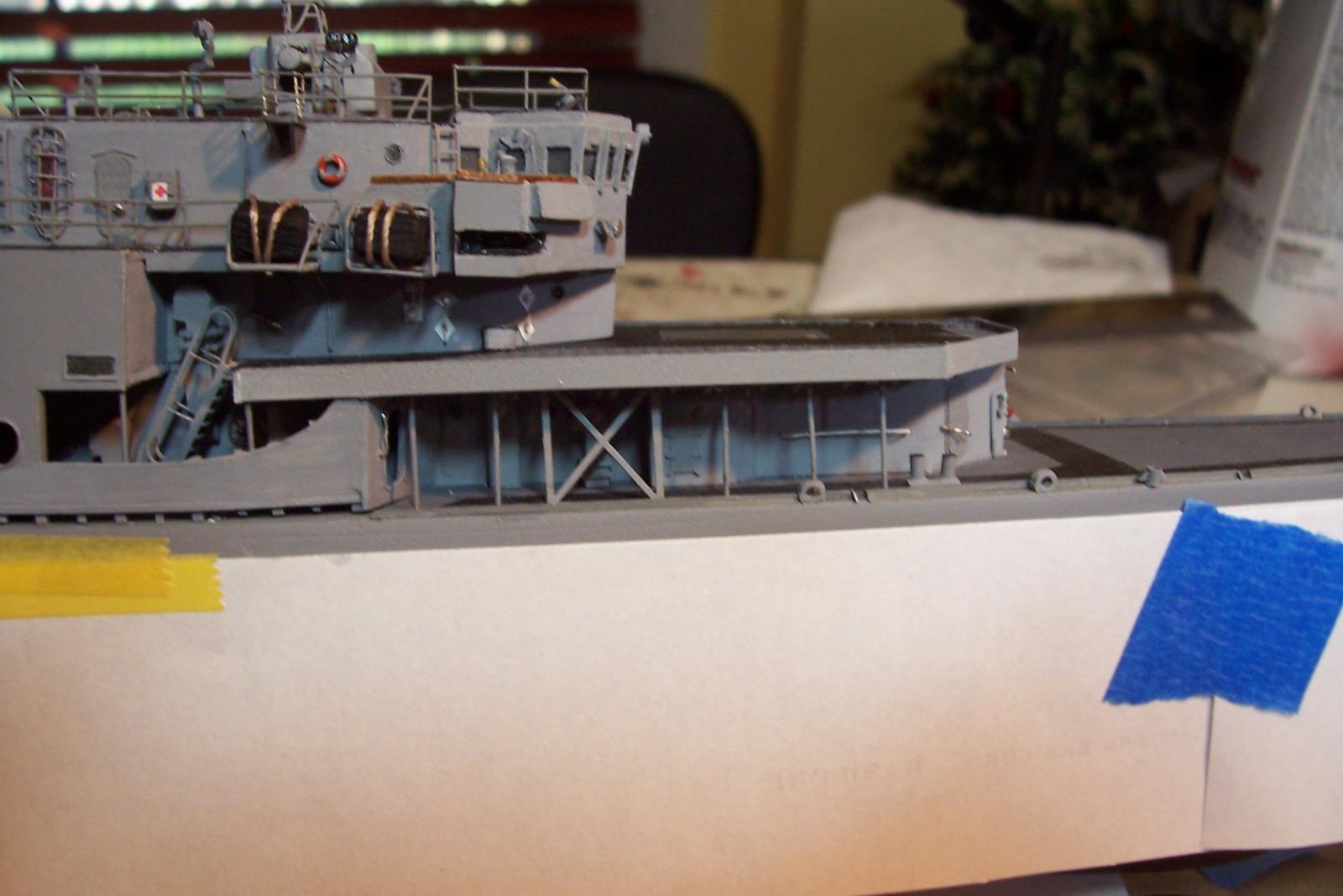
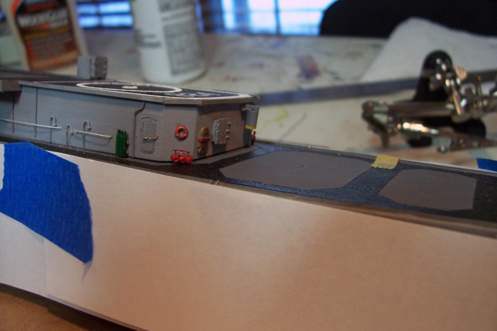
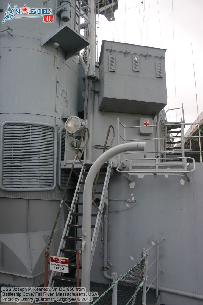
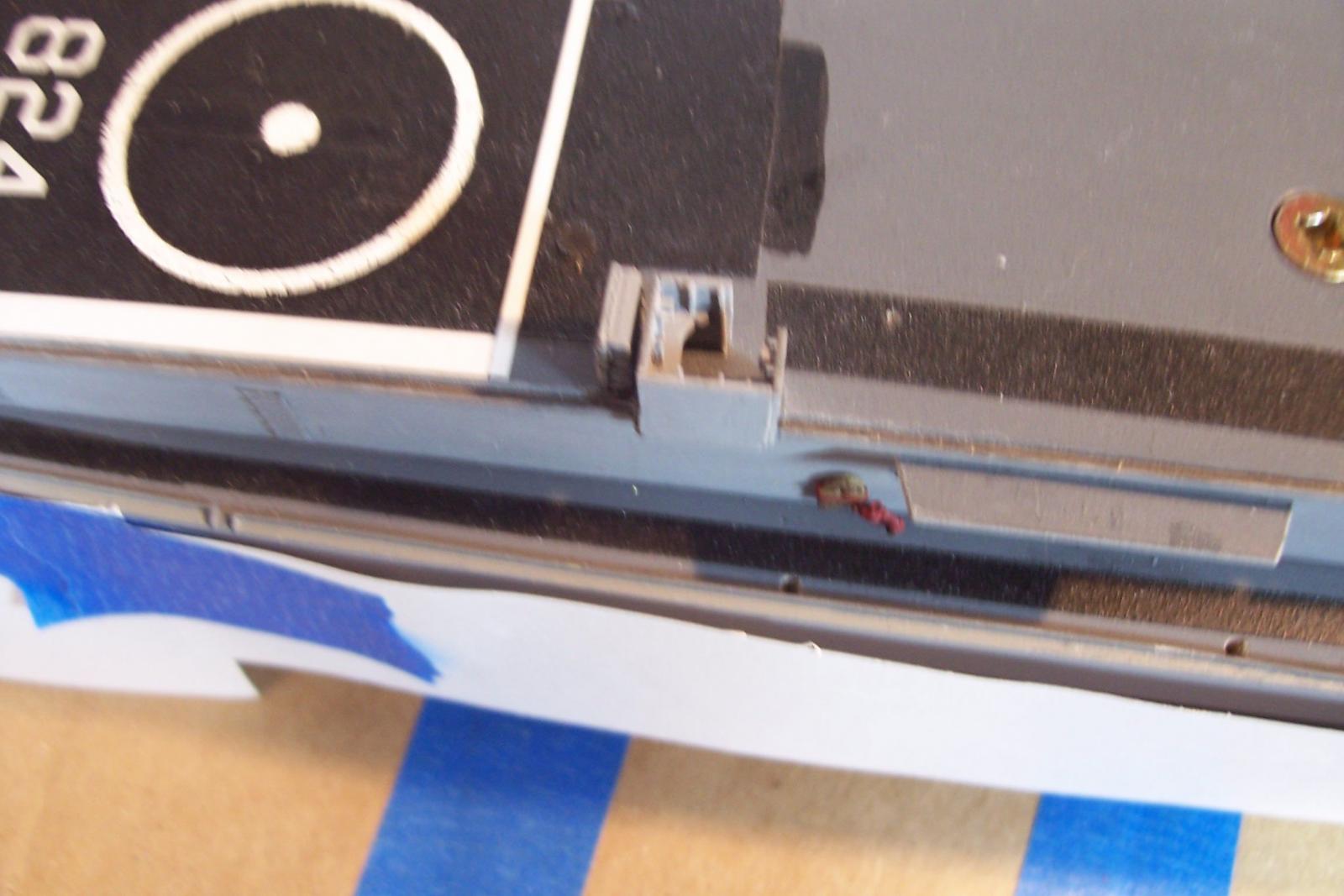
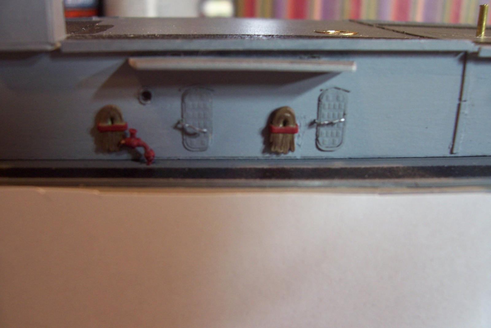
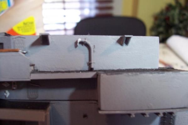
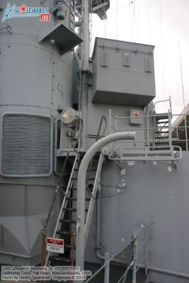
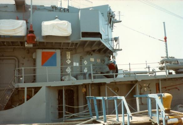
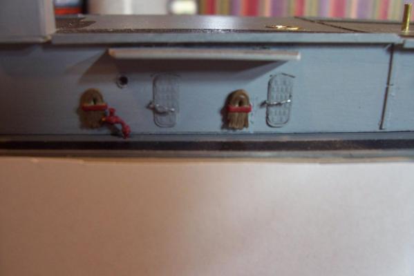
Fwd Refueling Station The FRAM’s primary station for refueling at sea was on the 01 deck forward, just under the bridge wings. The following photo shows the bulkhead fittings for securing blocks, long links and large cleats. It also shows the squat refueling trunk on the deck between the 2 large cleats. Forward of the trunk is a more modern probe receptacle which were added in the early 70’s and are still in use today - much better than lashing an open-ended hose into a trunk and hoping there won’t be spray of bunker oil coming out. I scratched the bulkhead fittings out of brass wire, styrene and paper: Here’s the completed station with the fuel trunk added. Also added is the trunk extension below it leading down to the main deck. The kit plans don’t show it but it is an easy addition:
- 144 replies
-
- 6
-
-
- basilone
- BlueJacket Shipcrafters
- (and 2 more)
-
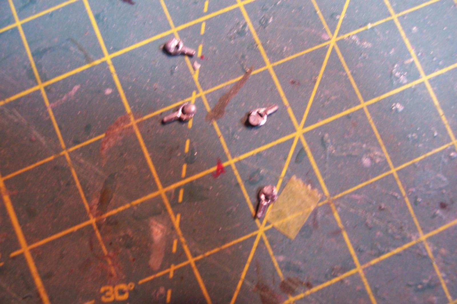
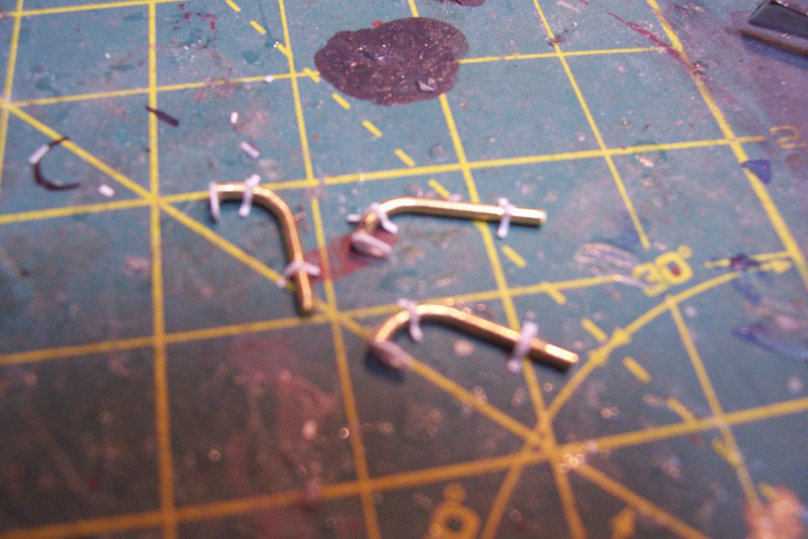
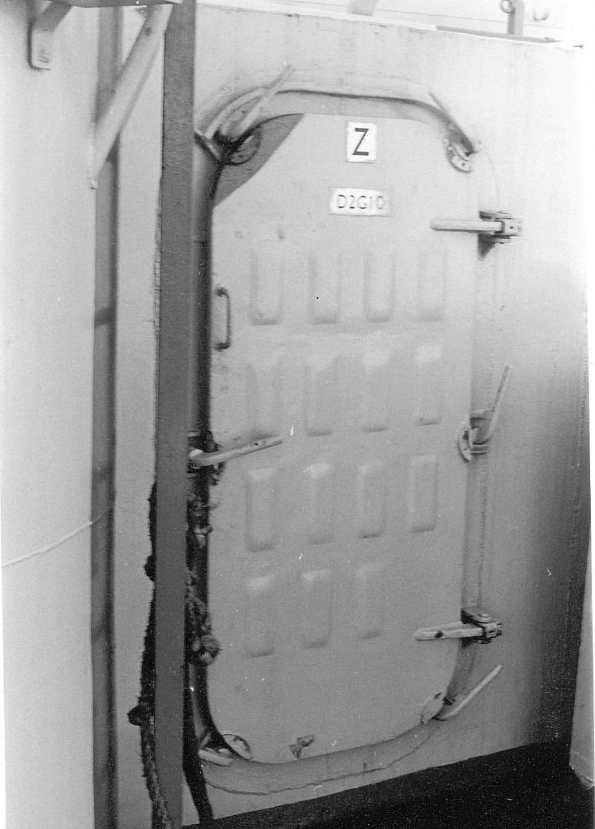
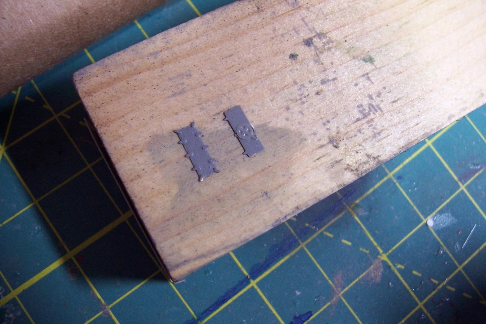
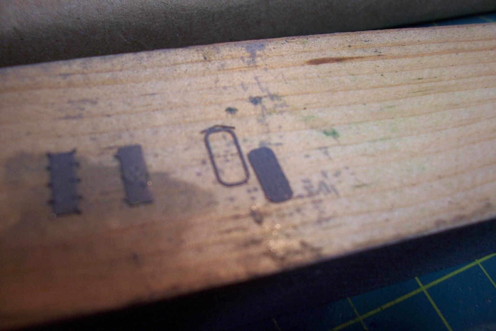
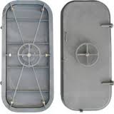
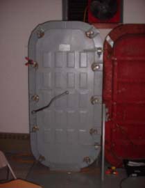
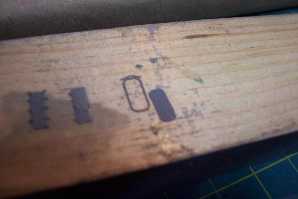
Superstructure details Prior to mounting the 2 main superstructure pieces to the hull I wanted to add the watertight doors, portholes and hose racks since it is easier to do while holding the larger pieces rather than the hull. There are about 30 WTDs on the ship, about 1/3 are what are referred to as “water tight doors” that have 8 individual dogs that have to be opened, these are used on doors that are not frequently used, like fan rooms, here’s what one looks like: The majority of the doors are “Quick-acting” type where all the dogs are connected by linkages. During WWII the USN used a style that had a hand wheel in the center and the linkages mounted on the door like this: Later they went to an improved design that has a lever and the linkages are mounted on the door frame so they are not so prone to get out of adjustment from the door slamming, here’s one: The kit provides PE doors for the WTDs and the QAWTDs: The kit WTDs (on the left above) are great, the thickness is right and the dogs are prominent. The kit QAWTDs are also fine but they are the WWII type and Basilone had hers removed during the FRAM upgrade and replaced with the modern ones with levers. So I ordered a fret of 1/192 USN doors from Tom’s Modelworks. They provide a wide range of door designs with waffle imprints , flat, and both exterior and interior sides. The doors come with a separate frame in case you want to model them in the open position, here’s one on the far right: The only problem with them is that there is no lever provided so I had to make my own. A 2 foot long lever scales out to 1/8 of an inch. I needed to include a 90 degree bend and 2 45 degree bends since the levers have a dog leg in them. I made a "3-step" jig that imparts the bends when the .010 wire is crimped to the jig with pliers and when the wire is clipped at the jig edge the length is correct. Making 20+ levers didn’t take too long. Each lever has a small bit of CA on the end to simulate the knob and then they were painted silver since the levers were usually left as unpainted steel. Here’s what a couple of them look like: After adding the doors I attached the 2 main superstructure pieces to the hull. I’ll be adding more details to the main deck bulkheads next because large areas of them will be obstructed with stanchions and bulwarks later on. I’ll continue with those details that show up on the blueprints like doors, stowed davits, etc and then fit in other details like drain pipes, fuel tank vents, grab rails etc using photos for reference.


- 144 replies
-
- 8
-
-
- basilone
- BlueJacket Shipcrafters
- (and 2 more)
-
Flying Fish by Reuben - Corel
schooner replied to Reuben's topic in - Kit build logs for subjects built from 1851 - 1900
Looks great Reuben, much more advanced than the introductory kits from Midwest Models that I started on. If you stick with this, without benefit of decent instructions, you will be able to tackle any kit out there. Trust me, when the instructions are good this hobby can even appeal to non-masochists. keep up the good work. -
Hey Eric, I just found your log. Nice to see another grey-hull build underway. Got to agree that Iron Shipwrights are the best in the business at customer support, even though their directions can be pretty obscure. Keep up the good work and keep the photos coming. Tim
- 176 replies
-
- 1
-
-
- new orleans
- iron shipwrights
- (and 2 more)
-
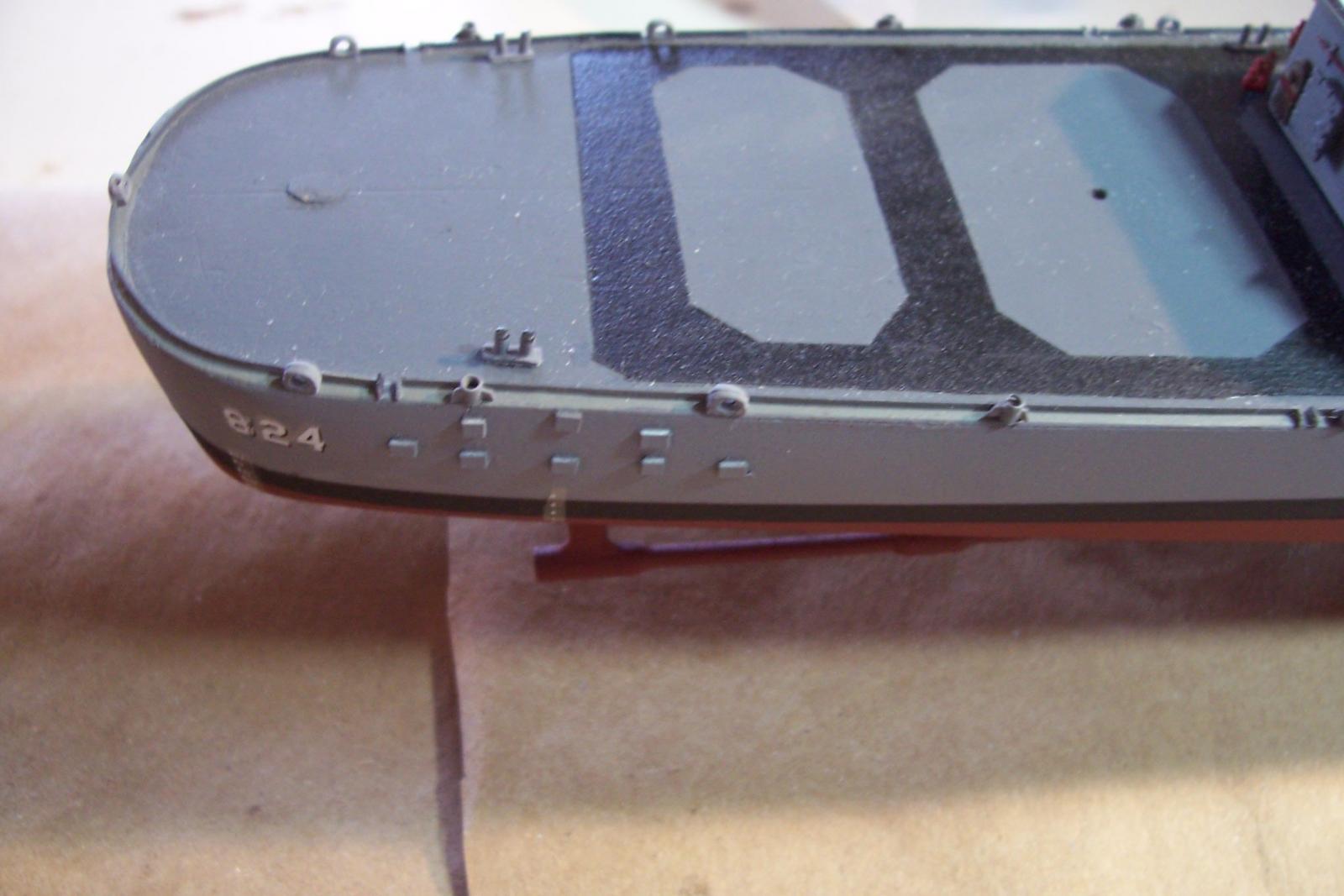
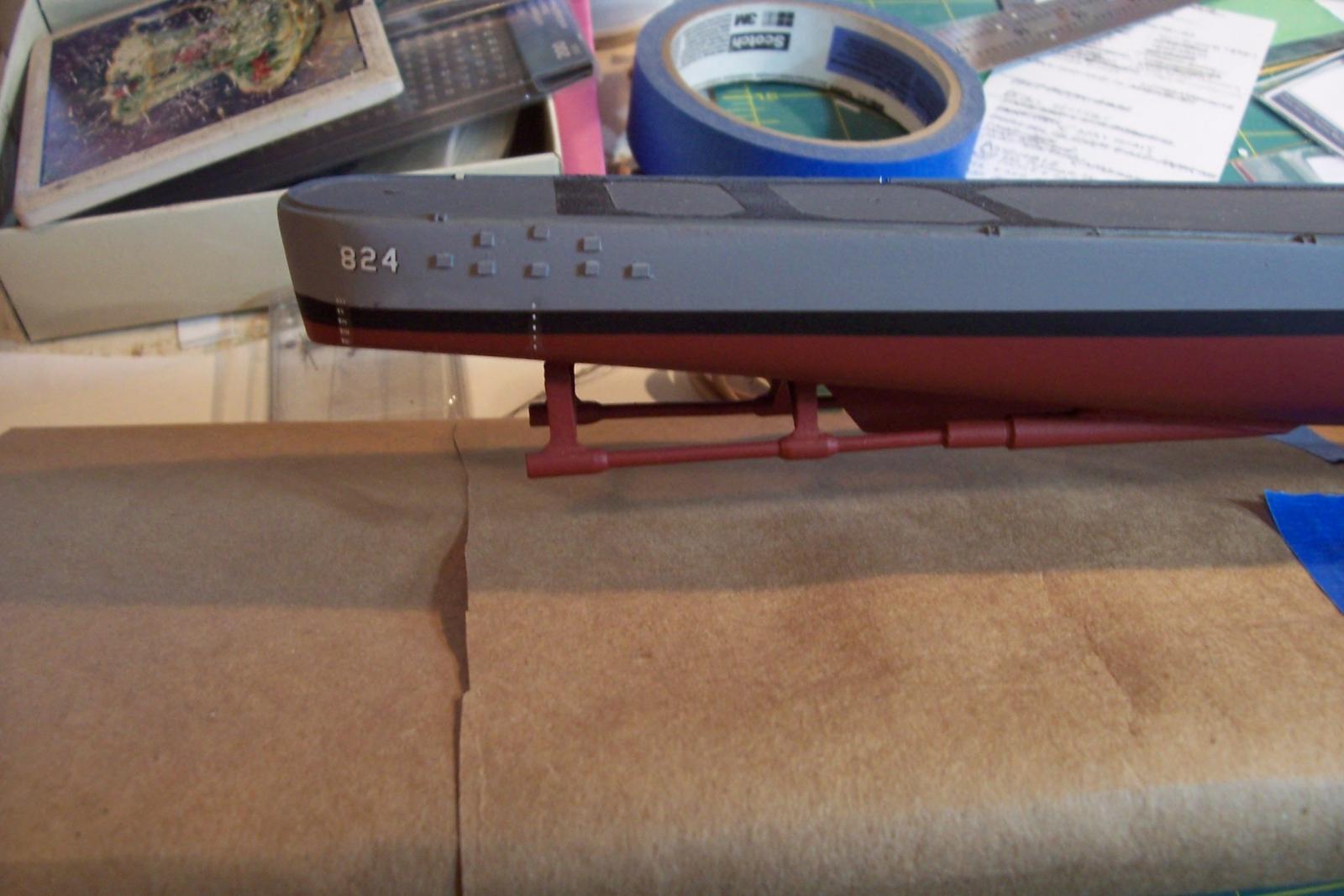
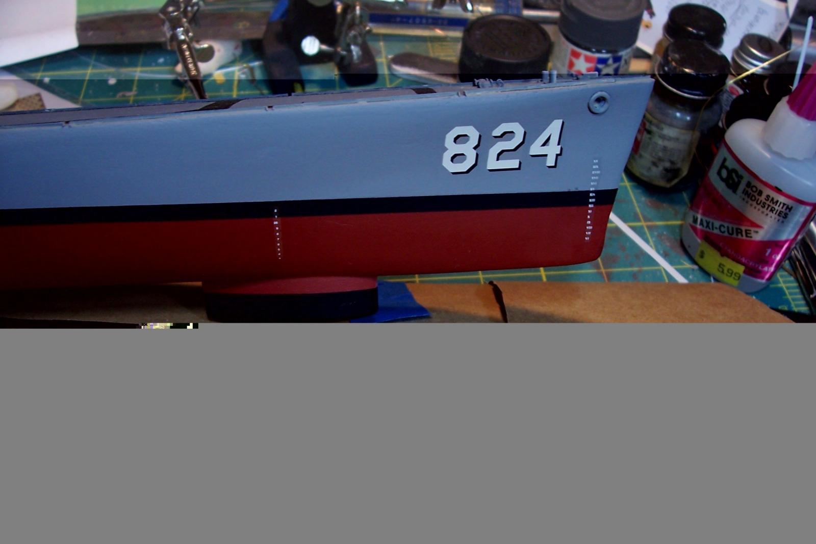
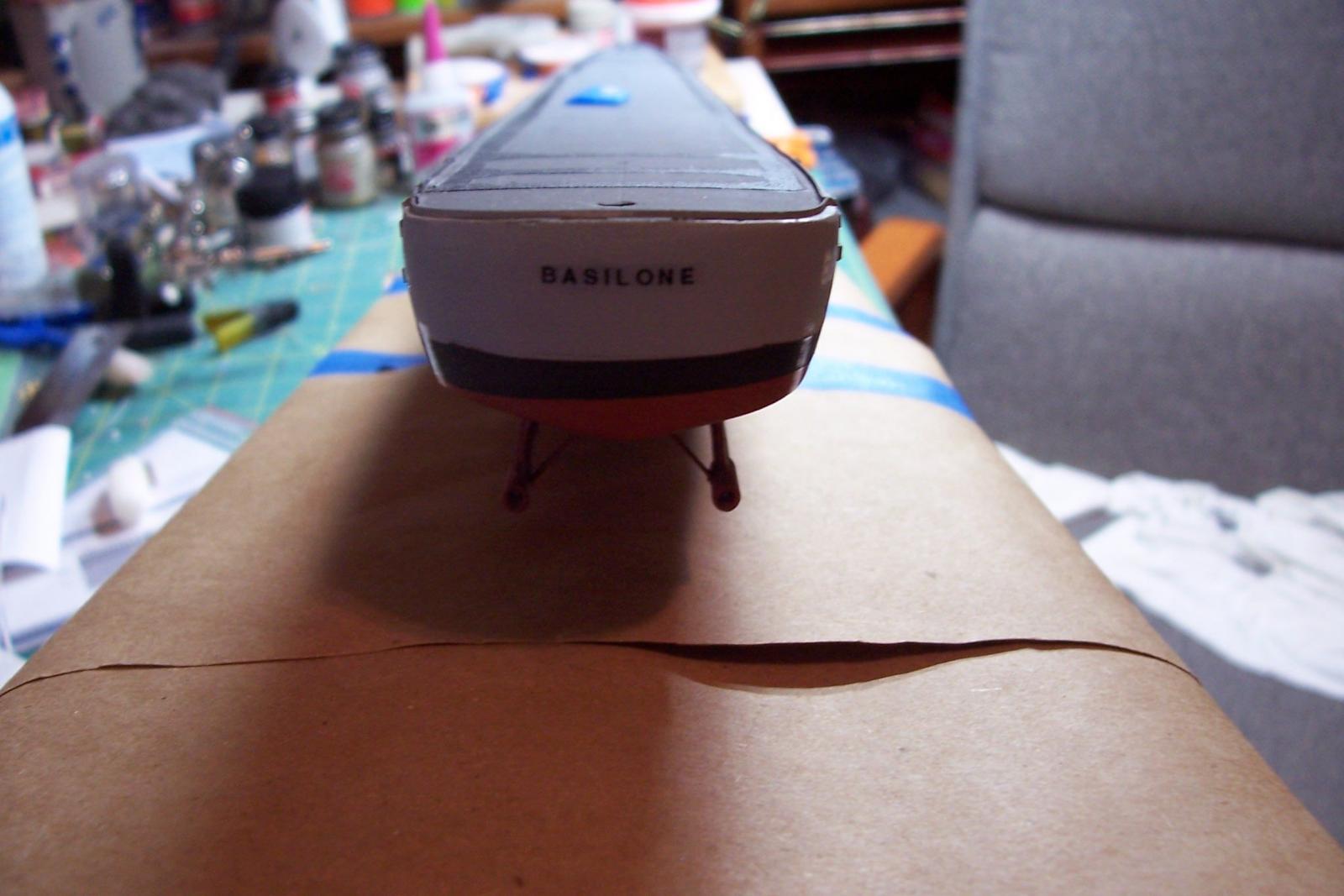
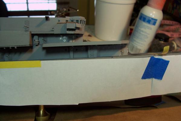
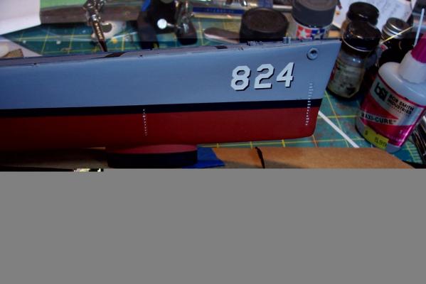
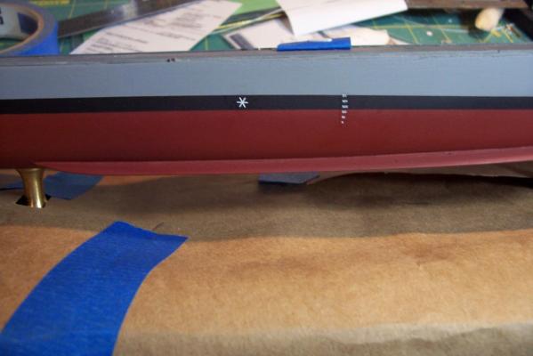
Hull decals The kit provides a decal sheet with the hull numbers for the USS Gearing, a name decal for the stern, 6 arabic numeral draft marks and the squadron shield. Since I’m modeling a ship other than the Gearing I had to look elsewhere for decals. I found what I needed from Gold Medal Model’s 1/192 USN decal sheet. For only $5 you get a wealth of shaded numbers, draft marks, warning signs, etc. If you want to duplicate the USN blueprints you will have to order 2 sheets because for some strange reason they only provide 1 white plimsoll mark (the asterisk looking thing) per sheet. A total of 12 roman numeral draft marks are required but they contain only 2 per sheet, however, there are so many numerals (I to XXXX), and they are right-justified, so that with a little careful work with a razor you can trim off the extra X’s and get what you need. The name decal was printed on blank decal paper. Applying them was easy with using Microscale’s MicroSet to pre-wet the surface and help the decals adhere without problems.

- 144 replies
-
- 11
-
-
- basilone
- BlueJacket Shipcrafters
- (and 2 more)
-
Thanks Patrick! Compared to cutting in a waterline on a planked sailing ship this was a piece of cake; no stem, no wales, no sternpost, no planking seams to suck paint where it doesn't belong.....
-
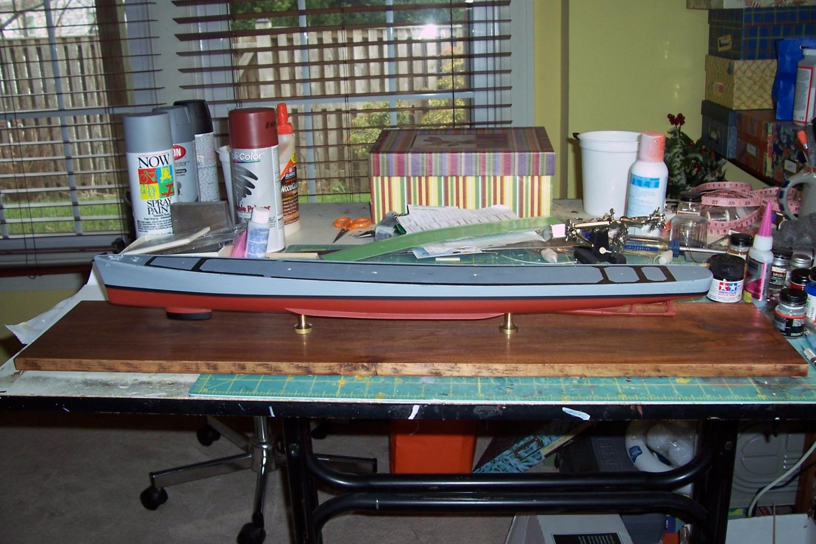
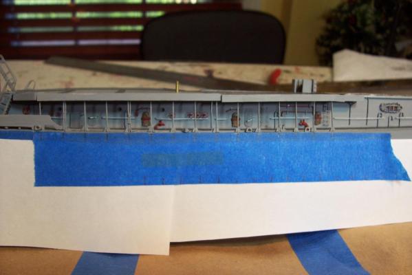
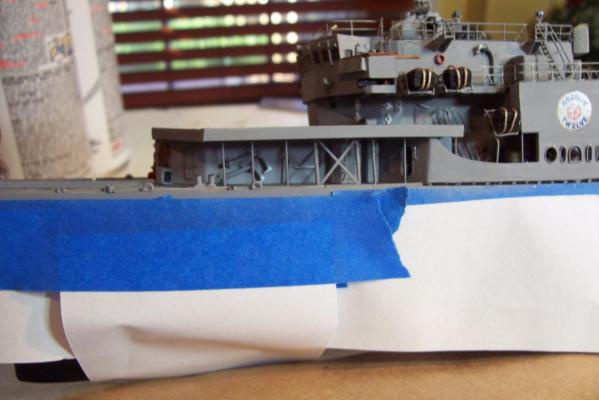
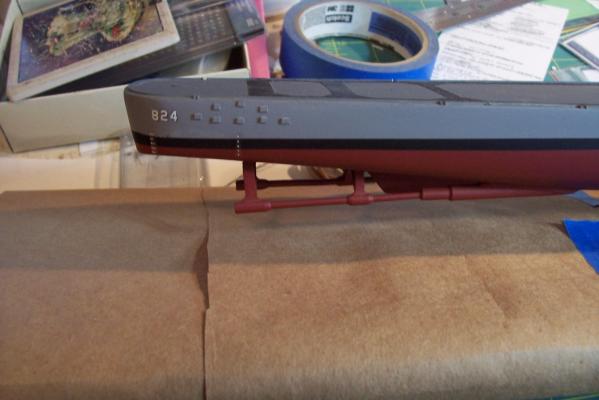
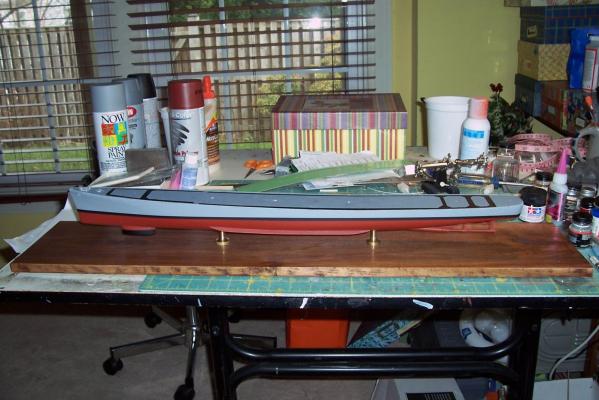
Hull painting and display board Finished up with the display board and then painted the hull. Nothing out of the ordinary, just a note for anyone building this kit: When it comes time to mark the waterline go with the side view on the kit plans, don’t reference the stern view, it’s height is off. I think since it is just a partial view it is supplied only to help locate the ship’s name decal. You don’t need it to locate the waterline anyway so just ignore it or you will spend 30 minutes trying to figure out why things don't line up (like I did). I’ll probably apply the decals to the hull next since I won’t want to have to handle the hull after all the delicate stuff is added topside. Then I will cover the hull sides and the board in protective paper until the end of the build.
- 144 replies
-
- 4
-
-
- basilone
- BlueJacket Shipcrafters
- (and 2 more)
-
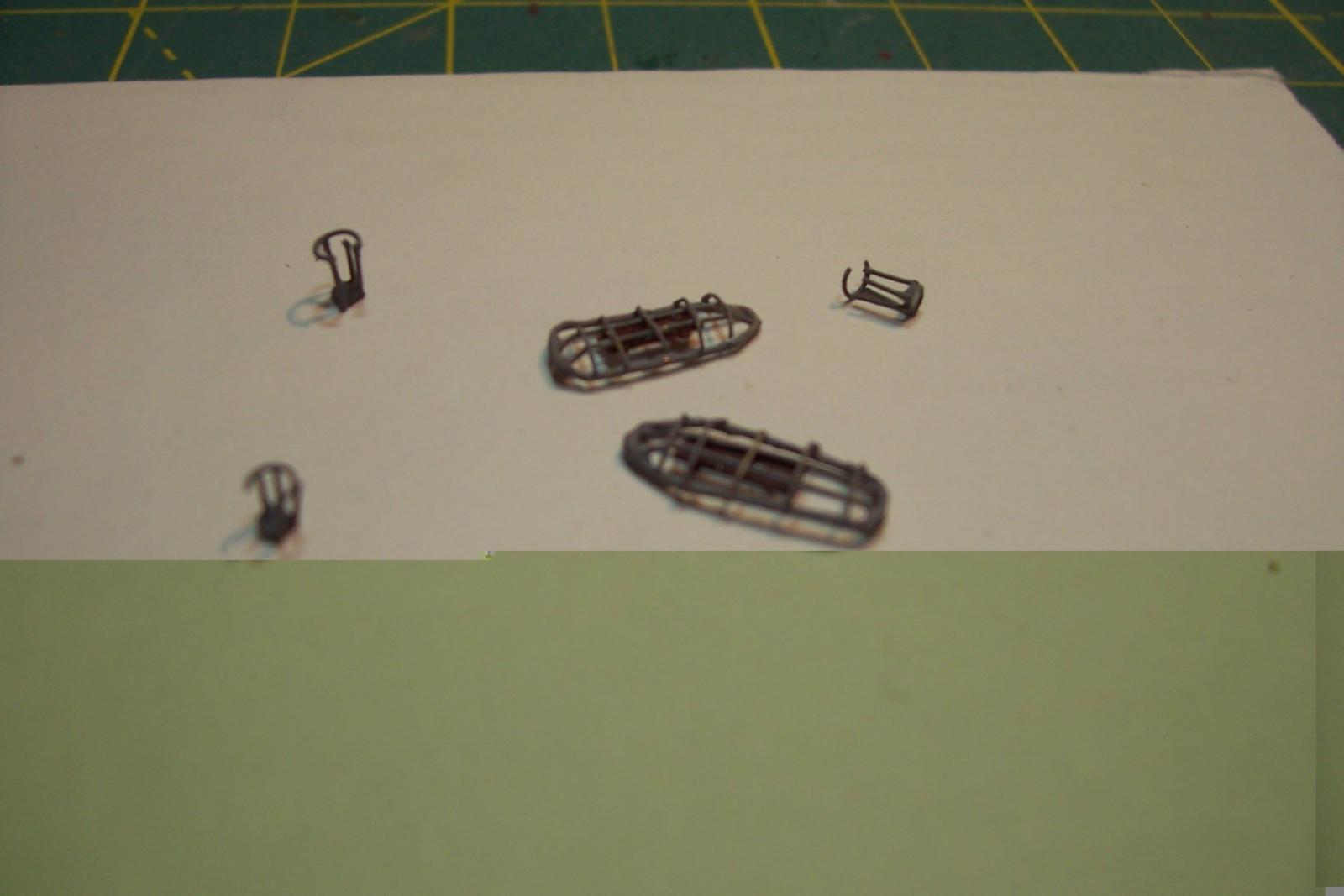
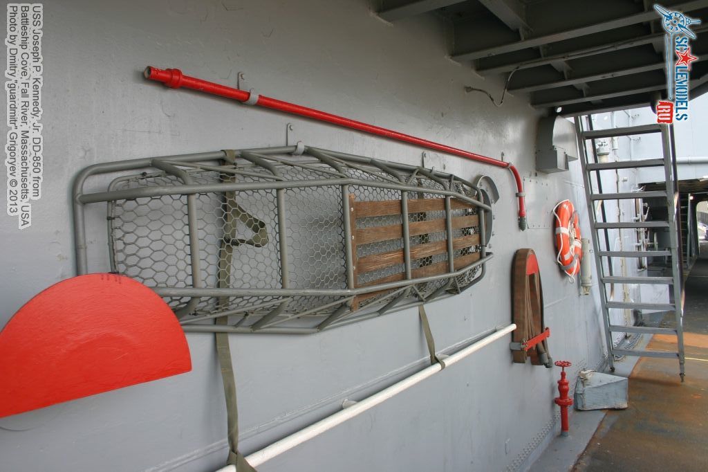
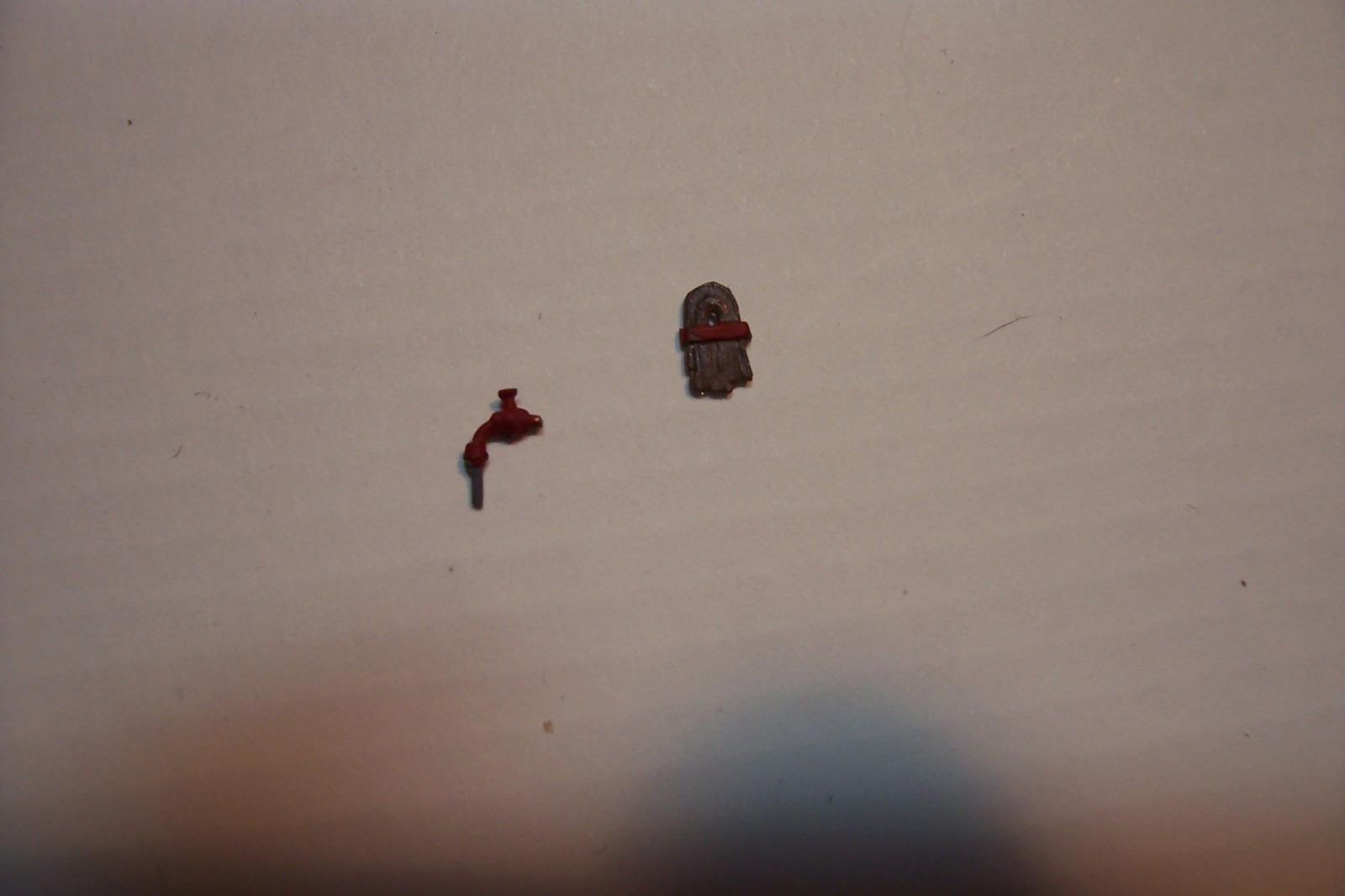
Odds and Ends While finishing up the display board I kept busy on some really small details Basilone carried 2 Stokes litters like this topside: I put together a couple out of wire and styrene, along with 3 helmet racks: This photo shows, in addition to another stretcher, some of the topside firefighting equipment. The kit provides several hose racks and associated 1/1/2 inch fireman risers in cast metal, both nicely done. Something I’ve noticed on ship models of USN ships of the period is that the canvas hoses are usually painted a very light tan color. That would stand to reason since you would assume that canvas exposed to salt water and sunlight would bleach out but in my experience a darker, dirtier brown is more accurate. New hoses came out of the shipping box a cardboard color and since they were constantly being taken of the racks for fire drills, saltwater wash downs and hydrostatic testing they got grungier with use until, when they finally wore out they were pretty gnarly, like the hose shown in the photo above. Associated FF equipment that was stored near the hose racks were the fog applicators that turned high pressure saltwater streams into a fine mist to shield the hose teams fighting fires in an enclosed space. They came in 4, 10, and 12 ft lengths and also special, unbent applicators that were stored near the gun mounts for emergency cooling of the inside of the barrels in case a round became jammed in a gun hot enough to cause it to cook off inside the barrel. Firing the guns once that point had been reached was always nerve-wracking. Here’s what I came up with using wire with CA globs for the tips, along with a couple of vertical and horizontal multi-valve 2 1/2 fireman risers (minus PE hand wheels enroute from L’Arsenal): I can finally put away the tweezers and hang up the magna visor for awhile as I shift to painting the hull, mounting it on the display board and pushing on to final assembly of the model.

- 144 replies
-
- 7
-
-
- basilone
- BlueJacket Shipcrafters
- (and 2 more)
-
Thanks for the kind words Patrick. I'm aware that what I'm doing here is just swatting flies compared to the reconstructive surgery you are carrying out on your constitution - amazing work, I have trouble even conceptualizing that kind of stuff in 3D let alone doing it.
-
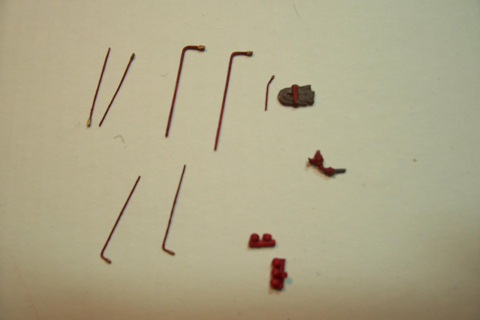
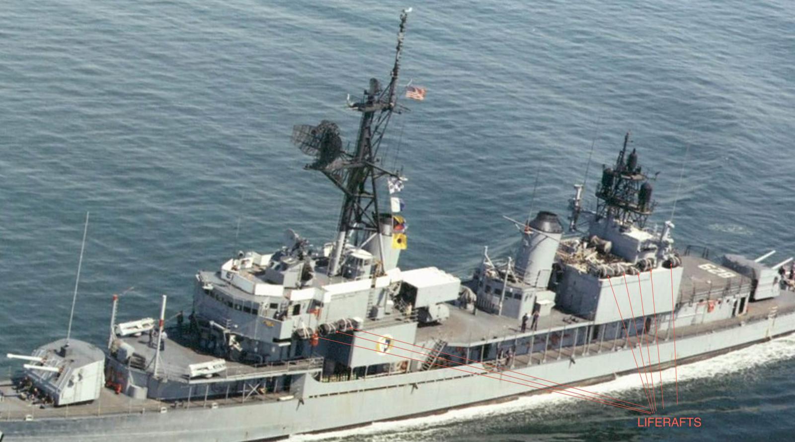
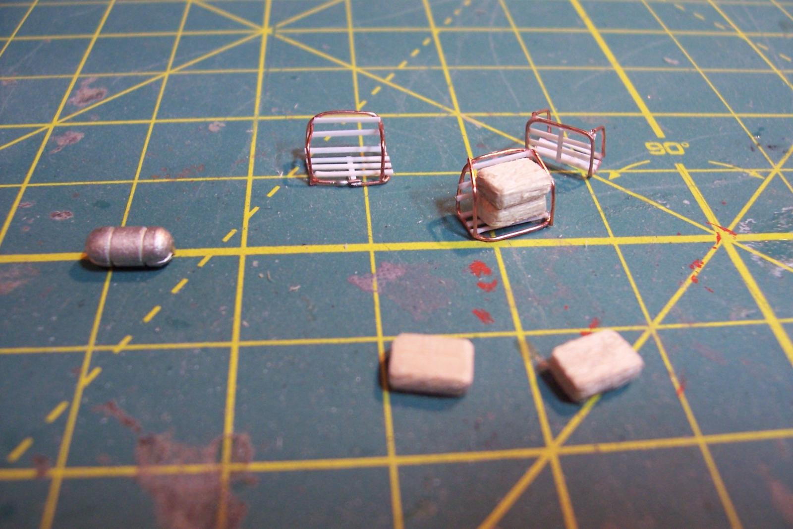
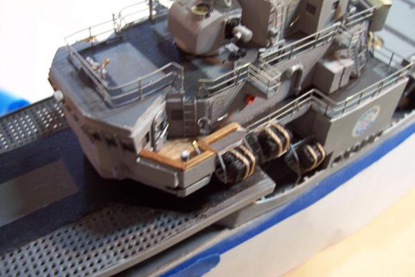
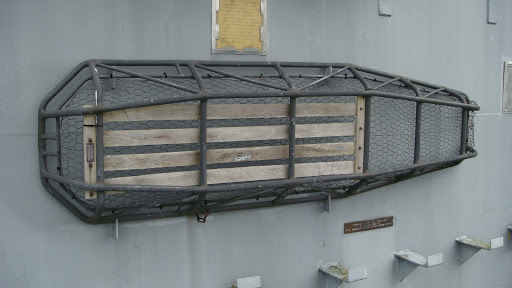
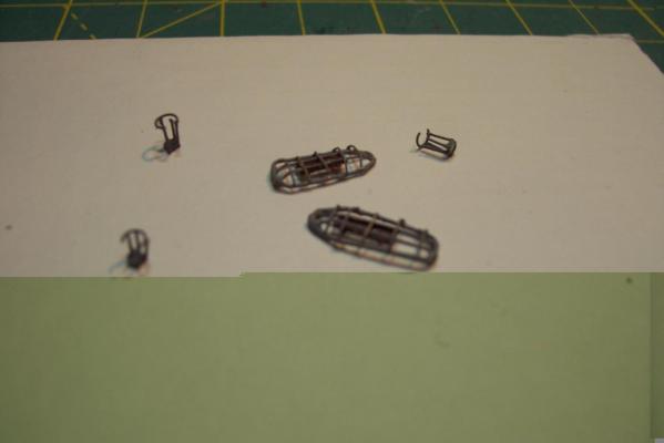
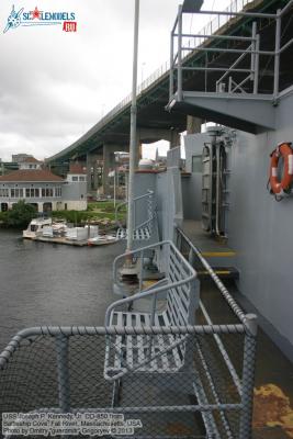
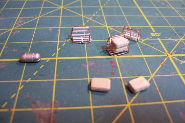
Inflatable liferafts Basilone was equipped with 19 25-man inflatable life rafts. The kit provides 9 cast rafts but the size and shape didn’t look right to me so I decided to scratch my own. The rafts were usually stowed in racks that resembled park benches like these: Half of the racks were on top of the hanger and the others were arranged on both sides of the forward superstructure: The rafts were stacked 2 to a rack and covered in rubberized canvas and secured with lines that ran to a hydrostatic release device that could be tripped manually or, if the ship sank, would release them at a relatively shallow depth. I scratched the rafts from strip wood of the right width, glued up to the right height, and then cut to length. The edges were rounded and the faces roughed up with a saw blade to simulate canvas. The racks are just a loop of soldered wire, bent and side rails added, with plastic slats. Here’s the stuff before painting (one of the cast kit rafts is on the left): And here is the finished product:


- 144 replies
-
- 7
-
-
- basilone
- BlueJacket Shipcrafters
- (and 2 more)
-
Thanks guys - I was afraid I was maybe becoming a little OCD about it all ...
- 144 replies
-
- 2
-
-
- basilone
- BlueJacket Shipcrafters
- (and 2 more)
-
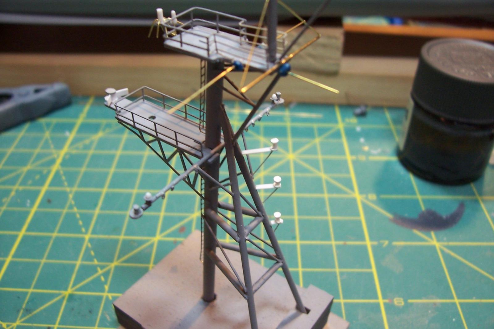
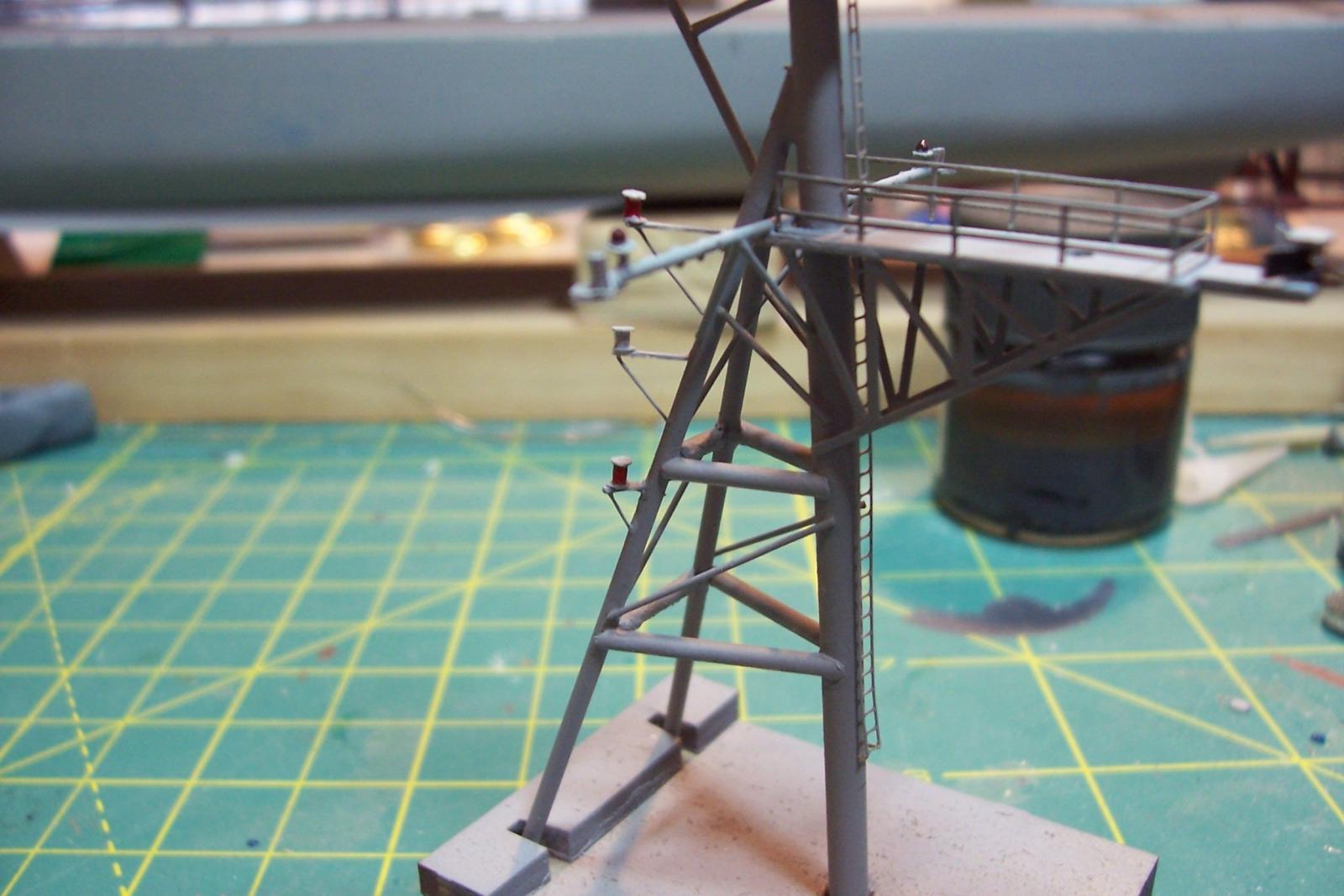
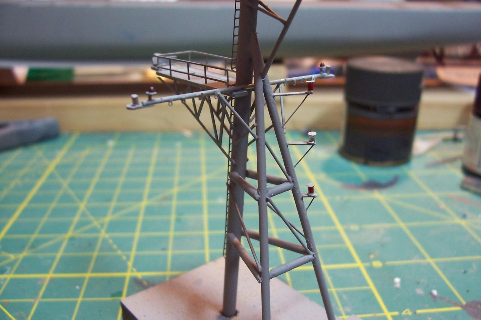
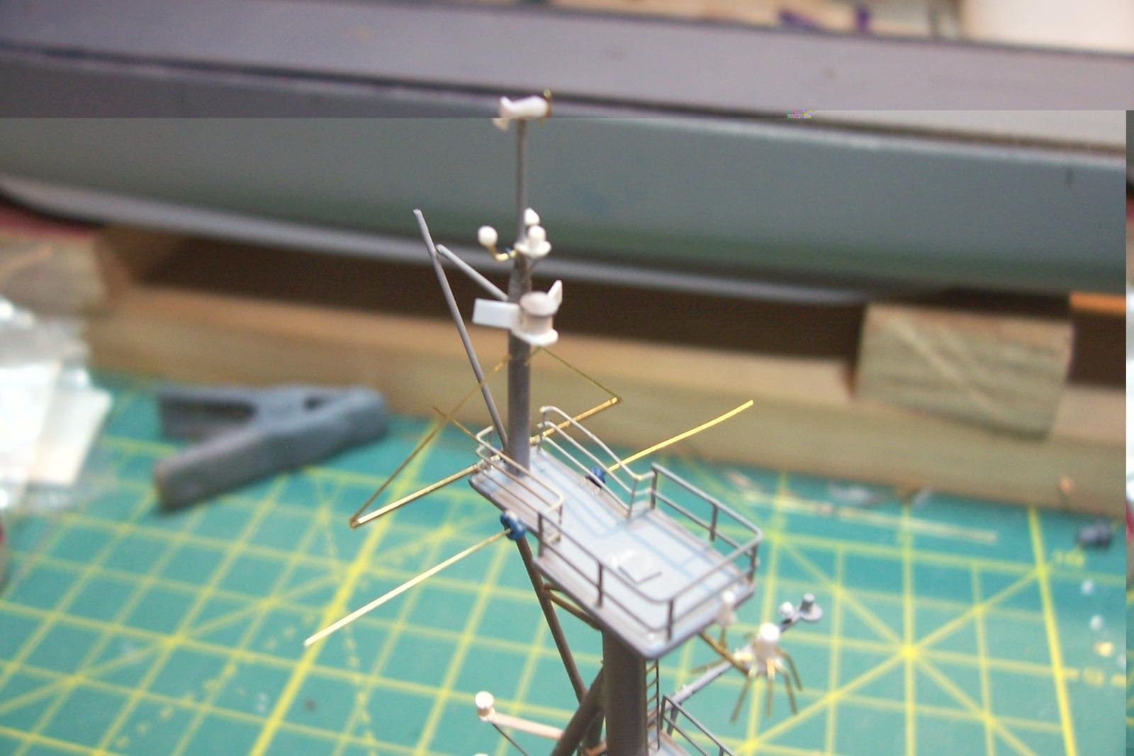
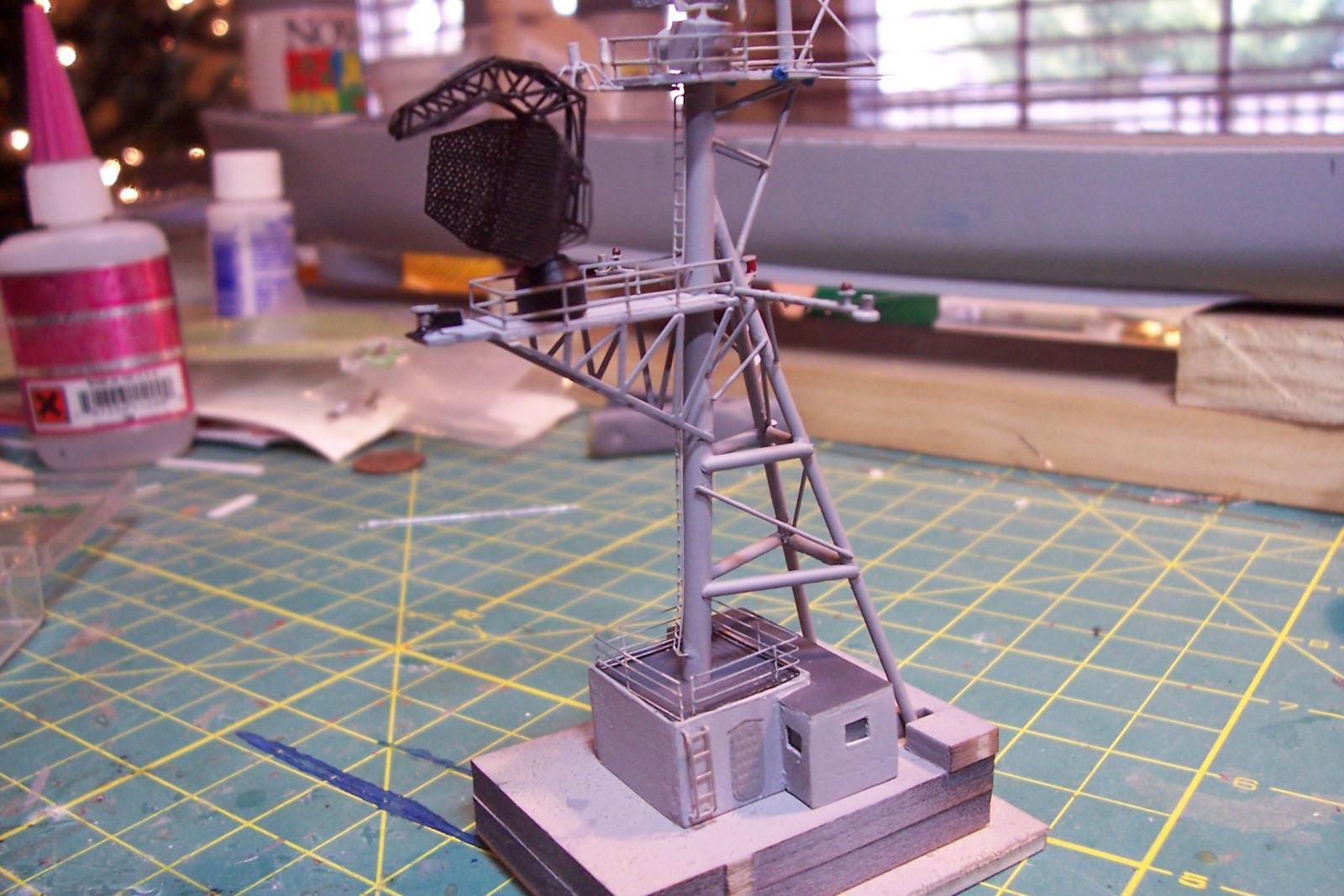
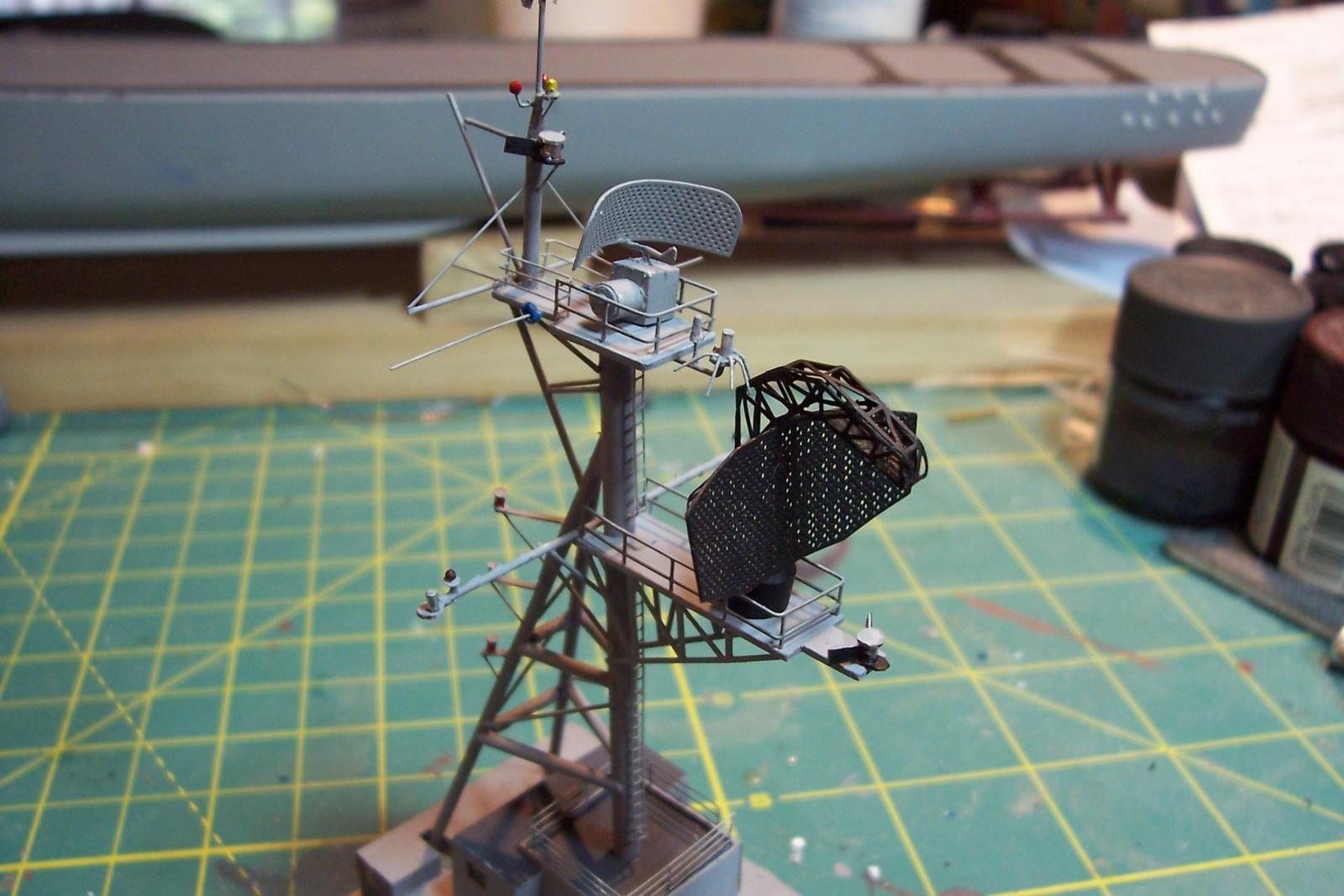
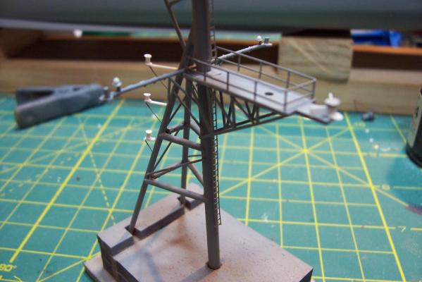
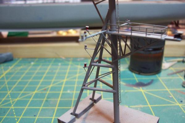
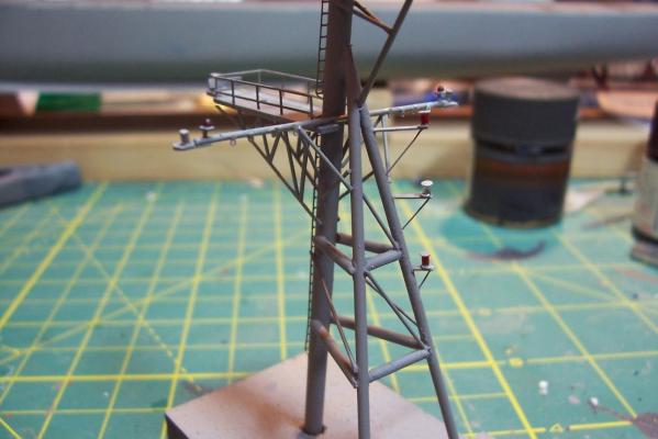
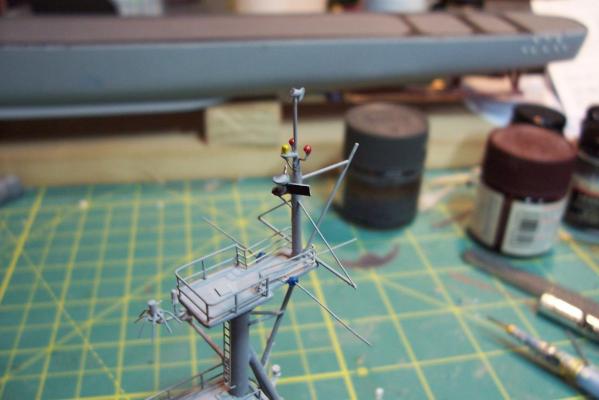
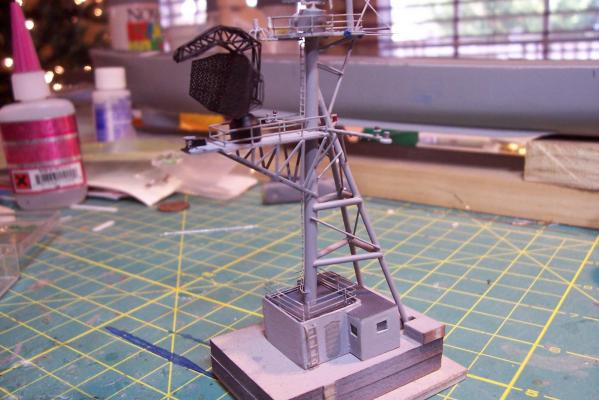
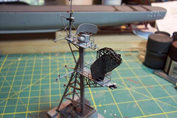
Main Mast (cont) Details were fabricated out of brass wire and styrene: Here they are after painting, to include several small whip antennas, 2 UHF antennas, masthead and range lights (the ones with the sector shields), the lights on the outer yardarms are omni-directional blinkers for sending messages to several ships simultaneously at night, just inboard of them are the Nancy lights, which perform the same function except stealthily using IR. The other lights include the yellow ASW light and red aircraft-warning lights on the masthead, and the red and white man overboard /task lights on the starboard mast leg. The small yardarm is actually a antenna spreader for a fan antenna that will be anchored on the forward stack, and last but not least there has to be a wind bird (anemometer) at the mast tip: Here’s what it will look like with the radar antennas and the signal shelter / ops office: I prefer the look of black masts on naval ships and Basilone had a black mast starting in the late 60’s but at the time I selected to depict her (1966) it was still grey (albeit, the big black radar antenna defeated much of the camouflage effect). USN masts have alternated between black and grey several times over the last hundred years as the emphasis shifts back and forth between the tactically prudent and the aesthetically pleasing. About 15 years ago they went back to the more tactically prudent grey again.


- 144 replies
-
- 6
-
-
- basilone
- BlueJacket Shipcrafters
- (and 2 more)
-
Great to hear from you again Patrick! Hope you will be posting again soon.