schooner
-
Posts
741 -
Joined
-
Last visited
Content Type
Profiles
Forums
Gallery
Events
Everything posted by schooner
-
 Thanks John, I've looked at the J.O. website as well as some others where folks have posted lots of walk-around photos. Between her and the John Brown up in Baltimore I think I'll have every thing I'll need to add details Tim
- 227 replies
-
- 4
-

-
- BlueJacket Shipcrafters
- Stephen Hopkins
- (and 2 more)
-
Dgbot, you're right, their kit is of the Jeremiah O'Brian, I'm going to modify the kit to reflect the Stephen Hopkins. The only differences between the two ships were the guns they carried. The BJ kit has what probably 90% of the Liberty ships carried. As one of the earliest Liberties launched, the Hopkins was fitted out with whatever could be scrapped together so I will have to scratch build the 4-inch gun, 2 37-mm AA guns, and modify the kit-supplied 20-mm guns into 50-cal guns. These are relatively small details, for all the big stuff like hull, superstructure and cargo booms the 2 ships were identical.
- 227 replies
-
- 6
-
-
- BlueJacket Shipcrafters
- Stephen Hopkins
- (and 2 more)
-
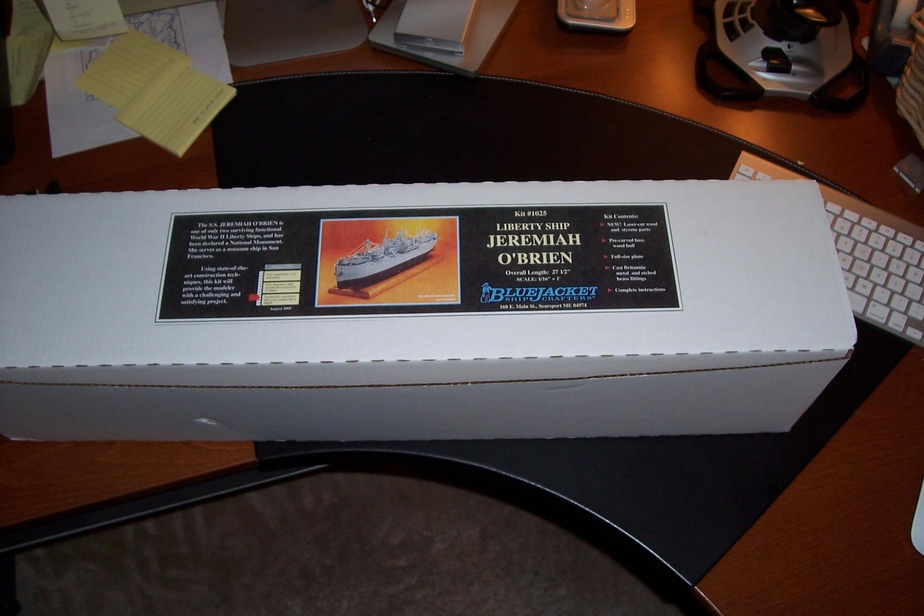
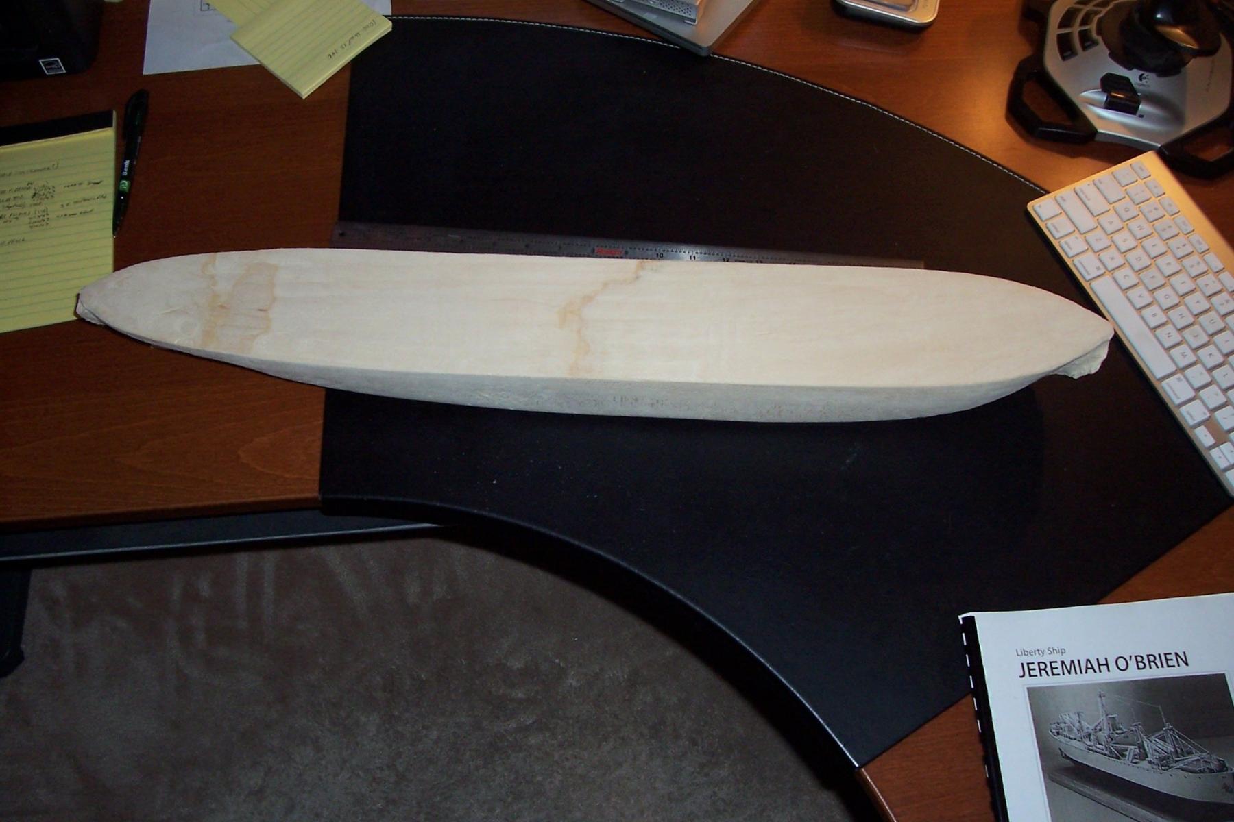
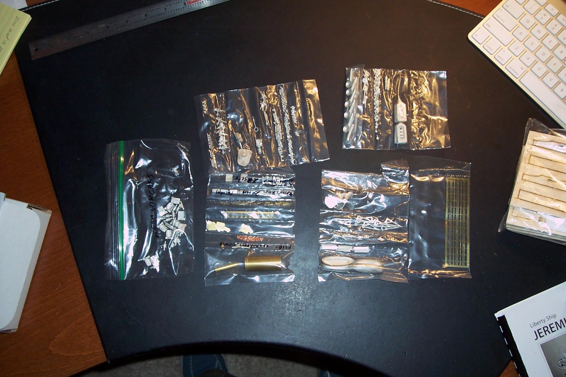
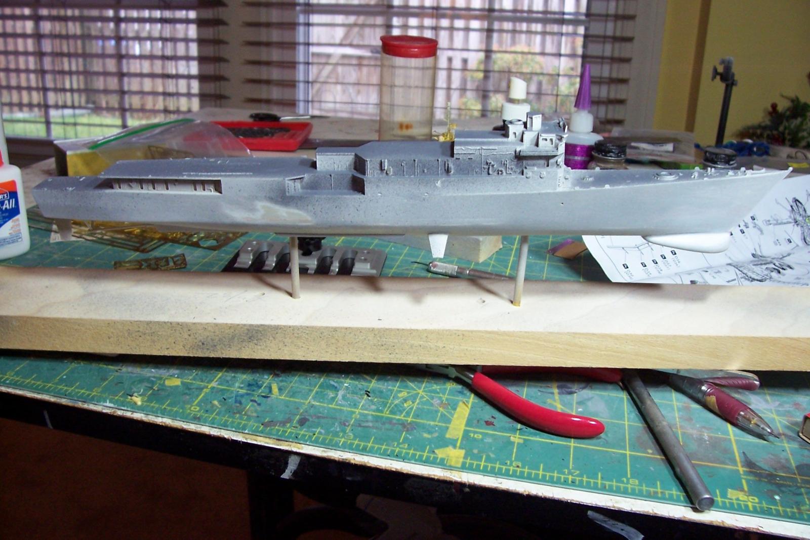
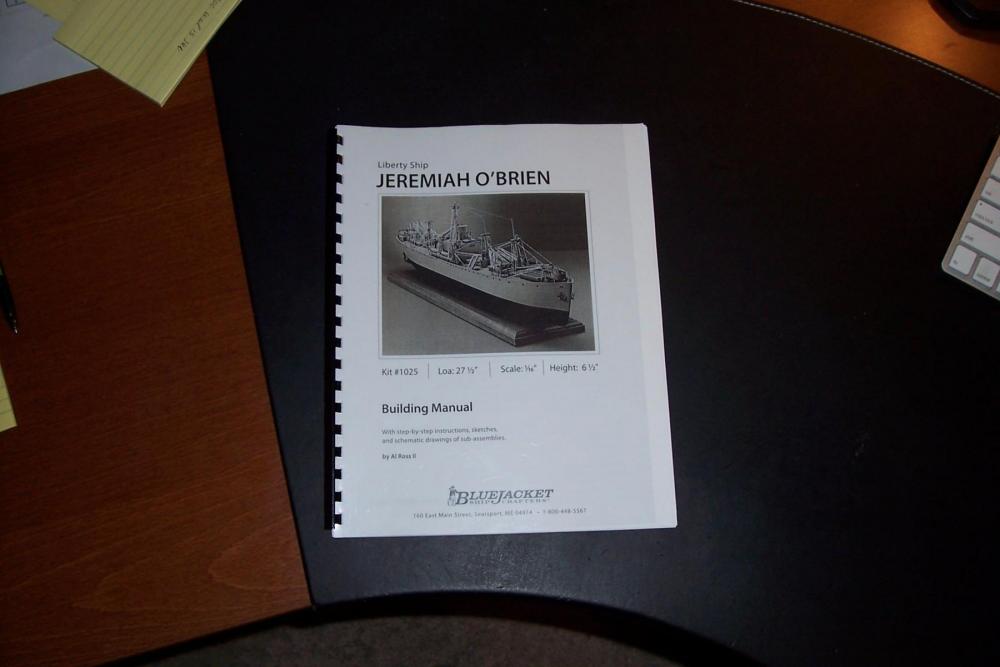
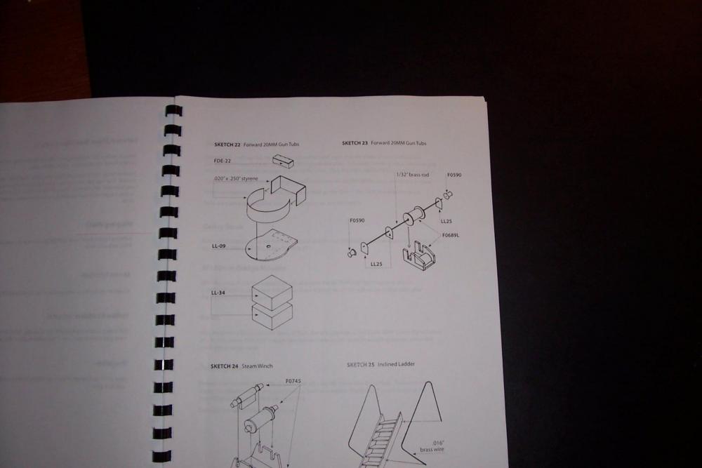
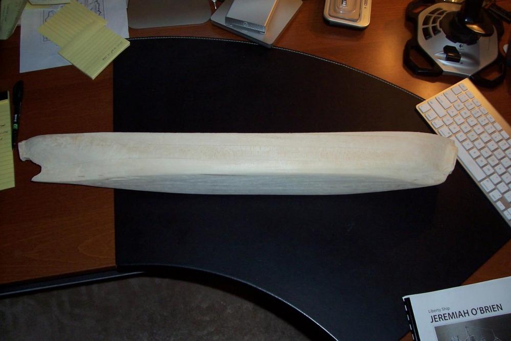
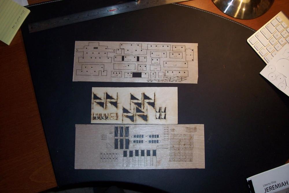
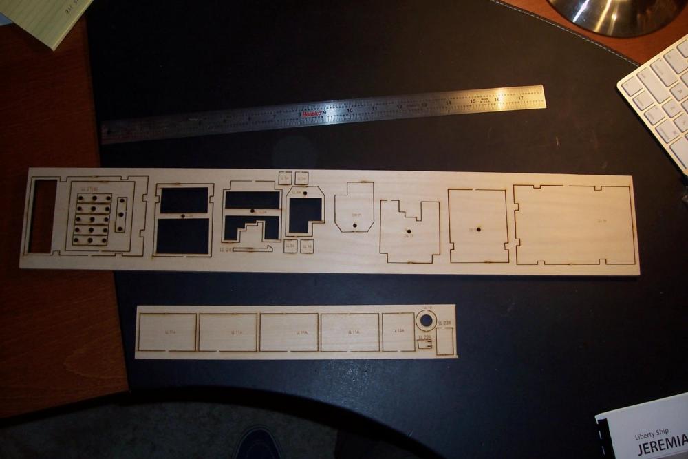
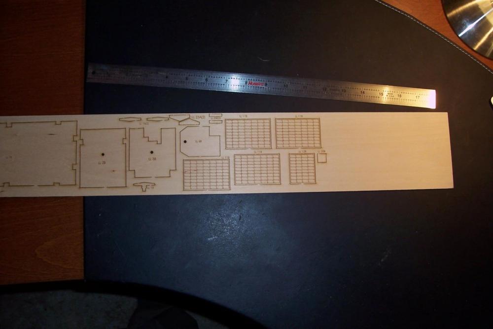
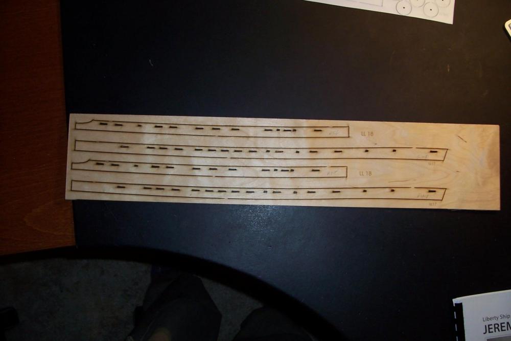
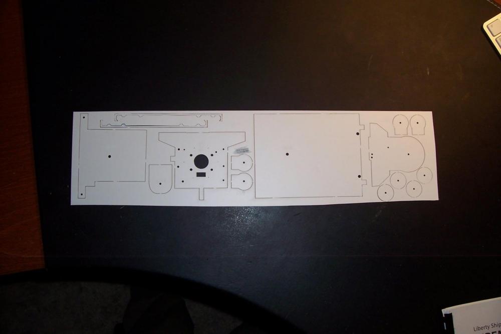
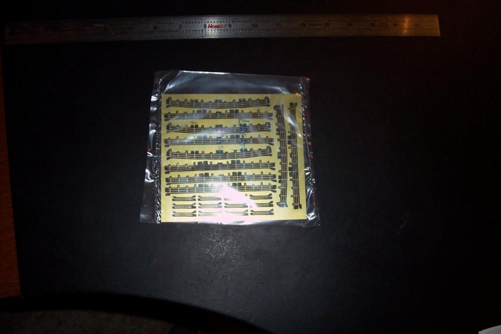
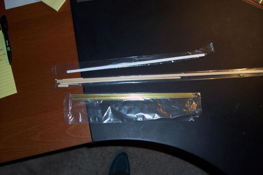
Liberty Ship SS Stephen Hopkins - BlueJacket Shipcrafters - 1/192 scale Kit Contents Although this kit has been in the BlueJacket inventory for quite a few years, it was updated just a couple of years ago to take advantage of new technologies and materials. Difficulty Rating BJ uses a 1-9 ranking to help customers figure out if a kit is within their skill level. They rank this kit “8” with the elaboration: “Construction experience with more complex kits is helpful.” I would not recommend this kit for a first time build mainly because the instructions tell, and sometimes show, WHAT to do but not always HOW to do it because prior experience is assumed. If you are interested in trying this kit I recommend you call Bluejacket and have a talk with them about your previous builds, they may recommend a simpler (and less expensive) solid hull kit to get you up to speed. Instruction Book The 28-page instruction book contains: a list of recommended tools (just simple had tools, nothing most folks would not have on hand) recommended construction sequence with explanatory sketches a parts list that should be used to inventory the kit on arrival (mine had everything) Plans 3 sheets of plans show the ship in both plan and view, fore or aft views of sub-assemblies where needed, rigging plan, and multiple copies of the hull lines which you cut out and glue to cardboard as templates for shaping the hull. Hull When I opened the kit the hull was wrapped in brown paper, I left it wrapped and put it aside while I looked at the plans. Looking at the stern area I thought “How am I going to shape the rudder area???!!!” since the rudder post sits on a integral projection of the hull that looked complicated to bring out. Fortunately when I got around to unwrapping the hull I found the rudder rest already carved. The basic hull shape and dimensions are in place. There are machining plugs at the bow and stern which are easy to remove, after that it is just a matter of sanding the hull until the templates for each station fit properly. The hull is 27.5 inches in length. Laser Cut One of the updates to the kit involved more use of laser cut wood. In addition to the expected pieces which are stacked to construct the deckhouses there were several pleasant surprises. Although the printed catalog photo of the finished kit do not show them, there are now etched hatch covers showing all the individual hatch covers. After discovering this I’ll be leaving most of the hatches uncovered and even trying to open a couple of them up. Another nice surprise was the bulwarks. I don’t know if they were always in the kit but I had assumed that like many solid hull kits with bulwarks I would have to carve down the deck leaving the bulwarks as a thin “fence” around the deck. On a model of this size that’s a lot of wood and I am a poor hand with chisels - I might as well use a chainsaw since it would be quicker and no worse than my chisel work. Fortunately the kit provides the bulwarks, with the scuppers in place (there are a ton of them). The bulwarks are simply attached to the deck edge along a rabbet. The last surprise is that thin facing pieces with portholes in place are provided to cover the exterior of the deck house. Drilling portholes has always been my bane, I either get tear-outs or have 1 or 2 that are out of line with the rest of them, now I don’t have to worry about that. There is also a sheet of laser cut plastic for gun tubs and other fittings. Photo Etch There is just a little PE supplied with this kit which is not surprising - it is used for delicate parts and there was nothing delicate about Liberty ships. Having just finished a 1/350 scale USN frigate with hundreds of tiny PE parts it will be nice to get away from that stuff for a while. Brittania Metal Fittings There are quite a few Brittania and brass metal fittings provided, all of them well cast and largely free of flash. This kit does not have any resin fittings. Misc. Parts There are wood dowels, wire, brass rod for fabricating parts and a sheet of rub-on letters specific for the Jeremiah O’Brian, and rigging thread. All told, it looks like there is everything needed for a nice model.


- 227 replies
-
- 15
-
-
- BlueJacket Shipcrafters
- Stephen Hopkins
- (and 2 more)
-
Dgbot - This will be a solid hull, it comes from Bluejacket about 85% to shape so it it just a matter of sanding it to final shape and dimensions, I will post a photo of the hull and other kit parts soon. Piet & Brian - welcome aboard, kit pictures to follow Robin b - I think you are referring to the USS Belinda, which was a fictional troop transport from the book and movie "Away all boats." I enjoyed both. This ship will look similar but smaller and without all the landing craft.
- 227 replies
-
- 6
-
-
- BlueJacket Shipcrafters
- Stephen Hopkins
- (and 2 more)
-
Wacko Wolf, Slog, Greg & David B, Thanks for your interest in the build, glad to have you onboard. Tim
- 227 replies
-
- 4
-
-
- BlueJacket Shipcrafters
- Stephen Hopkins
- (and 2 more)
-
Al, Here's what I was able to find about your father's ships, hope it helps: SS Sahale 1) Looks like you can get a photo from the Army Heritage and Education Center at: http://usahec.contentdm.oclc.org/cdm/ref/collection/p16635coll20/id/80714 2) mentioned in article about racial problems in 1942 at https://news.google.com/newspapers?nid=2211&dat=19420411&id=Bh0mAAAAIBAJ&sjid=sv0FAAAAIBAJ&pg=4829,1171630&hl=en 3) Ship’s Purser decorated for heroism in Sept 42 at http://www.usmm.org/heroes.html 4) Reported near torpedoing at http://uboatarchive.net/ESF/ESFWarDiaryMar42APP4.htm SS George F. Patten (note different spelling of last name) 1) listed in a USN convoy escort War Diary from Dec 1943 at: https://www.fold3.com/document/270948074/ 2) A local Mass newspaper with news from the troops in Jun 1945 mentions the ship as being in the Atlantic on pg 3 of the following (just above “Plummers News” at the following: http://spindle.trajnet.com/resources/v3-8.pdf 3) From: http://ww2ships.com/acrobat/us-os-001-f-r00.pdf Built at North East aShipbuilding Corp yard in Portland Me Hull # 802 Laid down 3/29/1943 Launched 5/22/43 Completed 5/31/43 Completed Service Mar 1970 Scrapped 4) involvement in a 1951 lawsuit at: http://www.leagle.com/decision/1956616144FSupp472_1525/UNITED%20STATES%20v.%20MOBILE%20TOWING%20AND%20WRECKING%20CO. SS Casimir Pulaski 1) from: http://ww2ships.com/acrobat/us-os-001-f-r00.pdf Built at Southeastern Shipbuilding Corp in Savannah, Ga Hull # 1053 Laid down 4/13/43 Launched 6/25/43/completed 7/16/43 Went to US Reserve Fleet at some point 2) probably a photo of the ship at https://www.jstor.org/journal/georhistquar 3) Included in a Merchant Marine officer’s memoirs at: https://books.google.com/books/about/The_Memoirs_of_a_Seagoing_Soldier_in_Wor.html?id=jX84twAACAAJ 4) photos from a sailor who served on the ship in the Naval Armed Guard at: http://www.armed-guard.com/nanni.html SS Marine Devil 1) Not a Liberty, but a larger C4 ship, listed here: https://en.wikipedia.org/wiki/Type_C4-class_ship 2) service mention at: http://en.allexperts.com/q/Military-History-669/2011/6/dad-service-eto.htm http://cbipage.tripod.com/c-home.html http://www.45thinfantrydivision.com/index12.htm 3) Photo available on Google under “SS Marine Devil”
- 227 replies
-
- 6
-
-
- BlueJacket Shipcrafters
- Stephen Hopkins
- (and 2 more)
-
Hi Alde, Believe me I know how hard it can be to find pix of individual ships. Have you tried Googling each ship's name with SS in front of it? The attached URL lists all the ships and what ultimately happened to them but not their operational histories: http://ww2ships.com/acrobat/us-os-001-f-r00.pdf If you get a chance please post the names of his ships and I will see if I can find anything. Part of the problem I think is that although the government built the ships most of them where then turned over (leased maybe?) to individual shipping companies and the govt has no records thereafter. I found a book "the Liberty Ships" by Sawyer and Mitchell on Amazon as a used book for a few bucks but it doesn't give much more info for most of the ships than what is in the website above. As far as finding out where each ship went during the war that would probably be a research nightmare, given that the Navy only cared about them when they were in a convoy (many sailed independently at times) and most shipping company records were probably tossed when they went out of business. Tim
- 227 replies
-
- 5
-
-
- BlueJacket Shipcrafters
- Stephen Hopkins
- (and 2 more)
-
Hi John, I ran across the John Barry treasure news story when I was doing my research, sounds like there is still quite a bit coin onboard, hard to believe they were able to get it from so far down. Your right - SS does stand for steam ship Tim
- 227 replies
-
- 4
-
-
- BlueJacket Shipcrafters
- Stephen Hopkins
- (and 2 more)
-
Welcome aboard BV, Merchant Sailors like your dad were the unsung heroes of the war, especially those on the tankers.
- 227 replies
-
- 6
-
-
- BlueJacket Shipcrafters
- Stephen Hopkins
- (and 2 more)
-
Wow, nice build log, wish I would have found it sooner. I grew up just across Salmon Bay from Ballard where the Cudahy was built and I had a chance to work on some tugs in Seattle when I was younger. You are doing a great job on her, love the engine! Tim
- 208 replies
-
- 3
-
-
- john cudahy
- finished
- (and 1 more)
-
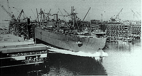
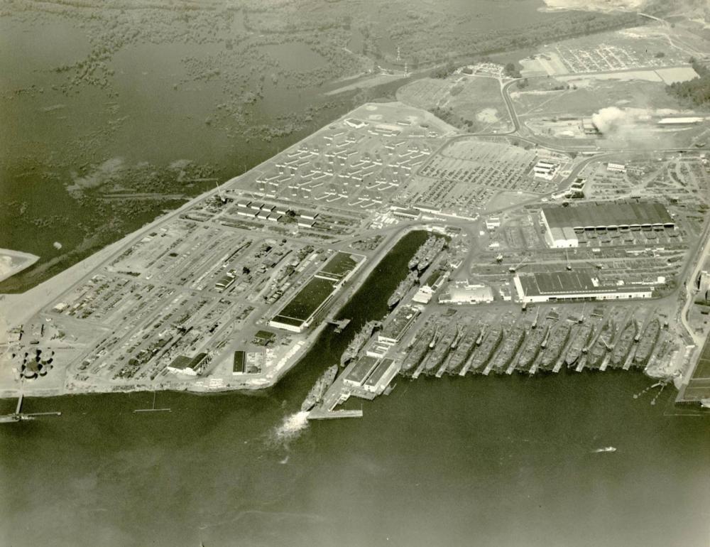
Great to have you onboard Steamschooner. Coincidentally, the aerial photo above showing the 11-way shipyard, is the Kaiser Portland Yard.
- 227 replies
-
- 5
-
-
- BlueJacket Shipcrafters
- Stephen Hopkins
- (and 2 more)
-
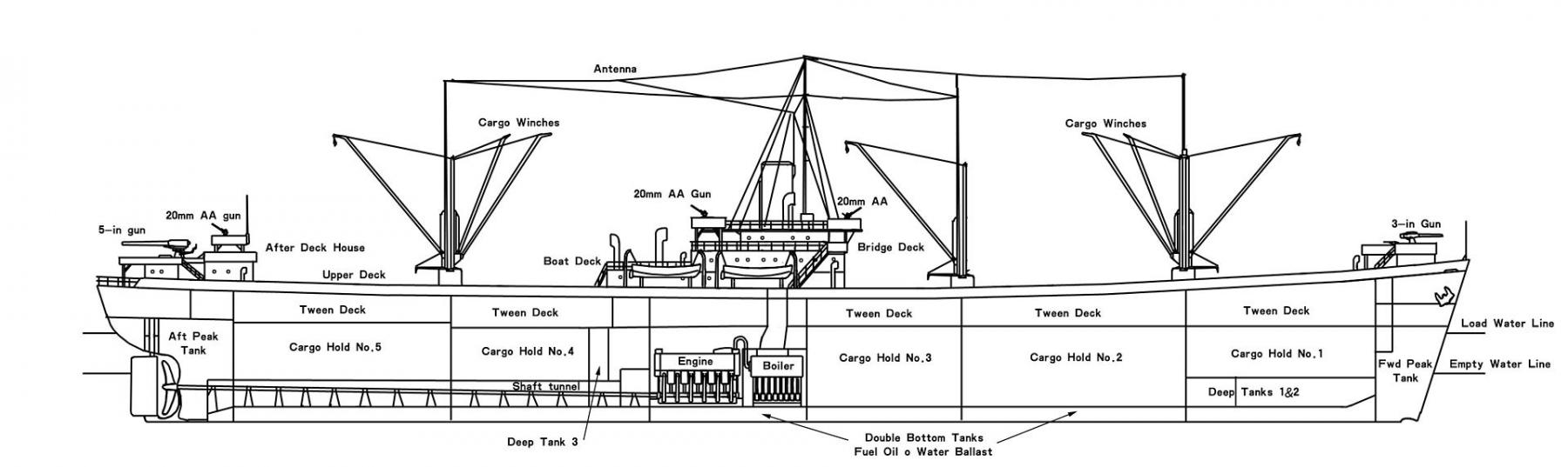
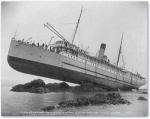
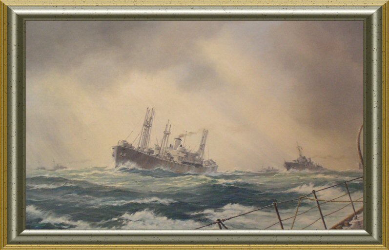
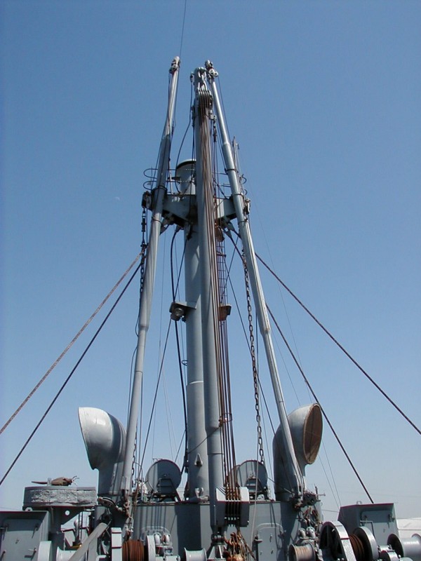
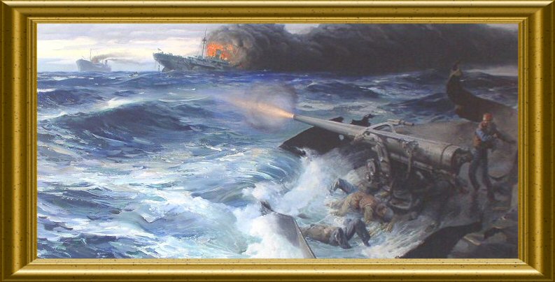
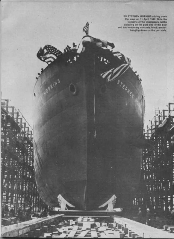
Liberty Ship SS Stephen Hopkins - BlueJacket Shipcrafters - 1/192 scale While mulling over what kit to select for my next build I was giving some thought to taking a break from warships and BlueJacket’s Liberty ship kit caught my attention because of the amount of rigging on it: Although I never served on any type of cargo or replenishment ship I figured “How complicated can it be?” Doing some photo research I came across the next photo of BIG CHAINS hanging from the masts of the SS John Brown and realized there is a lot I don’t know about cargo rigging and that this might be a good way to learn about it so I will be building BlueJacket’s kit of the Liberty ship SS Jeremiah O’Brian, which is still operating in San Francisco (BTW, I eventually found out that the chains are called Bull Chains). The next decision was what Liberty ship to model. With over 2700 Liberty ships built between 1941 and 1945 there is an embarrassment of ships to choose from but after a little research the choice was obvious. Although the Stephen Hopkins had a very brief life, being sunk on her maiden voyage, she would be a contender in any contest to name the greatest fighting ship in American history, despite being an “SS” vice a “USS.” It’s an amazing story, one that I’m surprised Hollywood hasn’t pick up on. So I won’t be taking a break from building warships after all . . . You can read her full story at http://www.armed-guard.com/hoppy.html, but in brief, after fitting out in San Francisco as one of the earliest Libertys, the Hopkins crossed the Pacific and the Indian Oceans, steaming alone and entered the South Atlantic where on 27 Sep 1942, in low visibility, she encountered at the range of about a mile two ships laying to. The ships turned out to be the heavily armed German raider Stier and the blockade runner Tannenfels. With a crew of 340, six 6-inch guns, torpedoes and numerous smaller caliber weapons the Stier had the armament of a light cruiser, in fact ten months earlier the similarly armed raider Komoran sank the cruiser HMAS Sydney off the West coast of Australia, although the Komoran was sunk also. The Stier opened fire immediately and the Hopkins’ Master decided to fight it out rather than surrender as most ships in her position would have done. The Hopkins’ single, obsolete 4-inch gun was moved by hand cranks and manually loaded but her Naval Armed Guard had been practicing at every opportunity and it began to show. The Hopkins quickly knocked out the Stier’s steering and repetitive hits along the waterline soon caused fires to break out in the Stier’s engineering spaces and she went dead in the water, as the Hopkins did too, with her boilers disabled. Both ships continued to drift and fight at about a thousand yards distance, like something out of the War of 1812. The heavy firepower of the Stier began to tell and after about 20 minutes the Hopkins was afire and sinking with two-thirds of her crew of 55 dead. Engineering Cadet Edwin O’Hara, from the US Merchant Marine Academy, made his way to the 4-inch gun after the engineering spaces were abandoned. He found the gun crew dead and the magazine destroyed but was able to locate 5 loose shells and single-handedly fired them at the Stier just before before he was killed. Nineteen survivors from the Hopkins managed to launch the one undamaged lifeboat. Meanwhile the Stier’s crew was unable to control the fires spreading out of the engine room and she had to be scuttled. Her survivors were recovered by the Tannenfels, who made no effort to aid the Hopkins survivors. Under the command of the 3rd Engineer and without any charts or navigation instruments except a compass the Hopkins’ boat set out to cross the Atlantic to Brazil. Amazingly enough they made it 30 days later with 15 men still alive. The ships were built in 18 purpose-built yards, which themselves were constructed in remarkably short time, turning mudflats into complex shipyards in just a few months. Locations of the yards were based on available manpower, however untrained, and political considerations to “spread the wealth” of government contracts across the coastlines. The Libertys were based on the then yet-to be built British “Ocean” design that was, in turn, based on successful coasters. The goal was to design a ship that was both inexpensive and quick to build, simple enough in design that inexperienced shipyards and workers could build them, that could make 11 knots and carry a significant amount of cargo. They departed from the British design in that they were largely welded, most of the accommodations were in a large deckhouse, rather than divided among the foc’sle, midships and aft.. Their boilers were water tube vice Scotch, and were oil-fired rather than coal. Without having to accommodate coal bunkers they could be fitted with heavier masts rather than king posts. Although by 1941 the advantages of turbines over reciprocating steam engines were well known, the technical skill required to build turbines was much greater and the small number of plants capable of producing them were all dedicated to warship construction so the decision was made to go with reciprocating engines. The Ocean design was further simplified to minimize the amount of curved plates in the hull and wherever possible bulkhead penetrations for piping were avoided by running them outside the skin of the ship. Cost saving measures included waiving a large number of US regulations related to Merchant ship safety, comfort and, ominously for the Hopkins, fireproofing. The ships had little in the way of forced ventilation and had the reputation of being hot and uncomfortable in most climates. Although the building time varied between shipyards , the common trend was that as they gained experience the time required to complete the ships steadily dropped. The first few could take up to 5 months to launch, although most only required a few weeks. The record was set by the SS Robert E. Peary, while admittedly a publicity stunt involving a lot of pre-fabrication and unlimited manpower, required only 4 days, 15 hours from keel laying to launch. By the end of the war an average of 3 Liberty ships a day were being launched. If you are interested in learning more about the Liberty ships this URL will take you to a decent study produced by the American Bureau of Shipping: https://www.eagle.org/eagleExternalPortalWEB/ShowProperty/BEA%20Repository/News%20&%20Events/Publications/WorkhorseOfTheFleet and this one will take you to a one-hour, color, wartime documentary film about the ships and the shipyard in Richmond, CA where the Hopkins was built: https://archive.org/details/cubanc_00004# I'll be using the following references: SS John W. Brown, a working Liberty ship berthed in Baltimore. Although she has some modifications from her conversion to carry troops and as a school ship in NYC she is still in remarkably good condition and largely unchanged from her WWII days. I was able to spend a few hours onboard, take a lot of photos, and watch the cargo booms at work. She takes day trips from ports along the East Coast. A Call to Arms by Maury Klein. Although the book covers the entire US WWII industrial mobilization, the chapter on shipbuilding is well done. Ships for Victory by Frederic C. Lane. Thank God I was able to get this from the library rather than spend any money on it. If 900+ pages of meeting by meeting and memo by memo descriptions of bureaucracy at work excites you then this is your book. Even while skimming it I was worried that I would pass out and then drown in the puddle of my own drool. The book provided some insight into the welding problems encountered in the early program but that was about it. Websites devoted to the SS John W. Brown, SS Jeremiah O’Brian, and SS Hellenic Victory all have extensive onboard photos to help with details 5) http://www.globalsecurity.org/military/library/policy/army/fm/55-17/ch3.htm is a webpage that has extensive info on cargo rigging, it will be my primary reference for rigging. In the next post I’ll give an overview of what comes in the kit


- 227 replies
-
- 18
-
-
- BlueJacket Shipcrafters
- Stephen Hopkins
- (and 2 more)
-
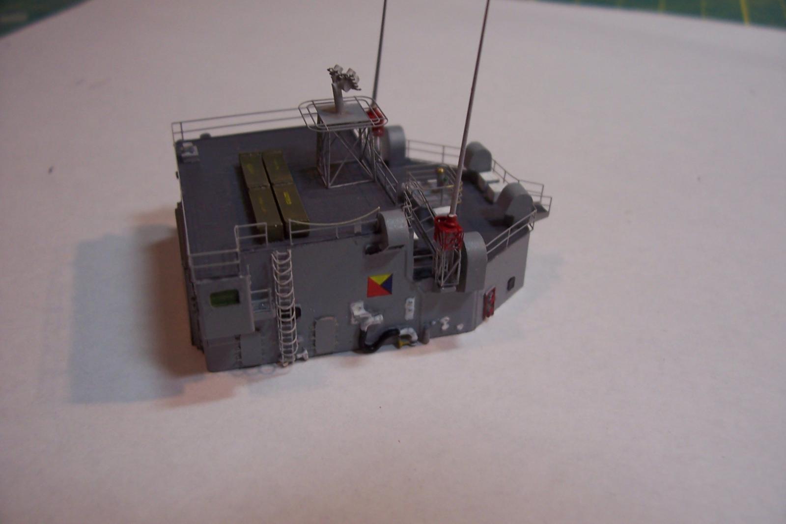
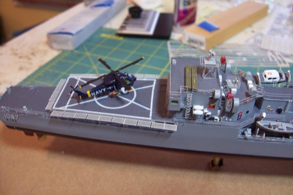
With the add-on of the lifelines, helo nets, and the helo the only thing left is to add the MACK and the rigging.
- 22 replies
-
- 9
-
-
- kirk
- orange hobby
- (and 4 more)
-
Hi Elijah, Hopefully she will fit on a shelf on a bookcase in my den - I really don't want to take up any more table top space since I'm afraid I may be approaching my wife's still undefined but undoubted ship model limit.
- 22 replies
-
- 4
-
-
- kirk
- orange hobby
- (and 4 more)
-
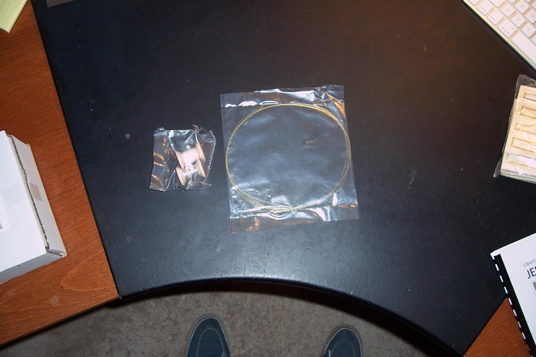
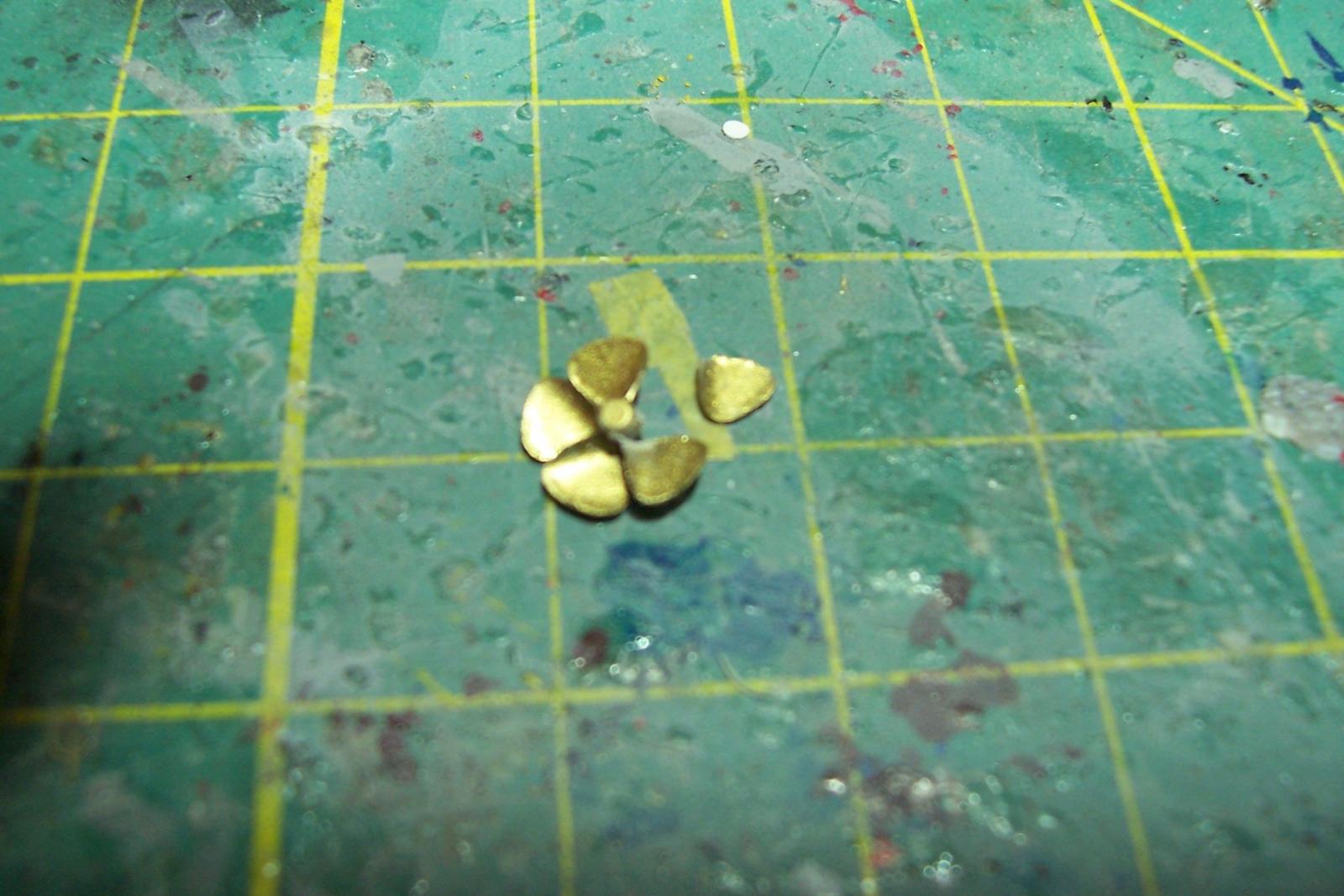
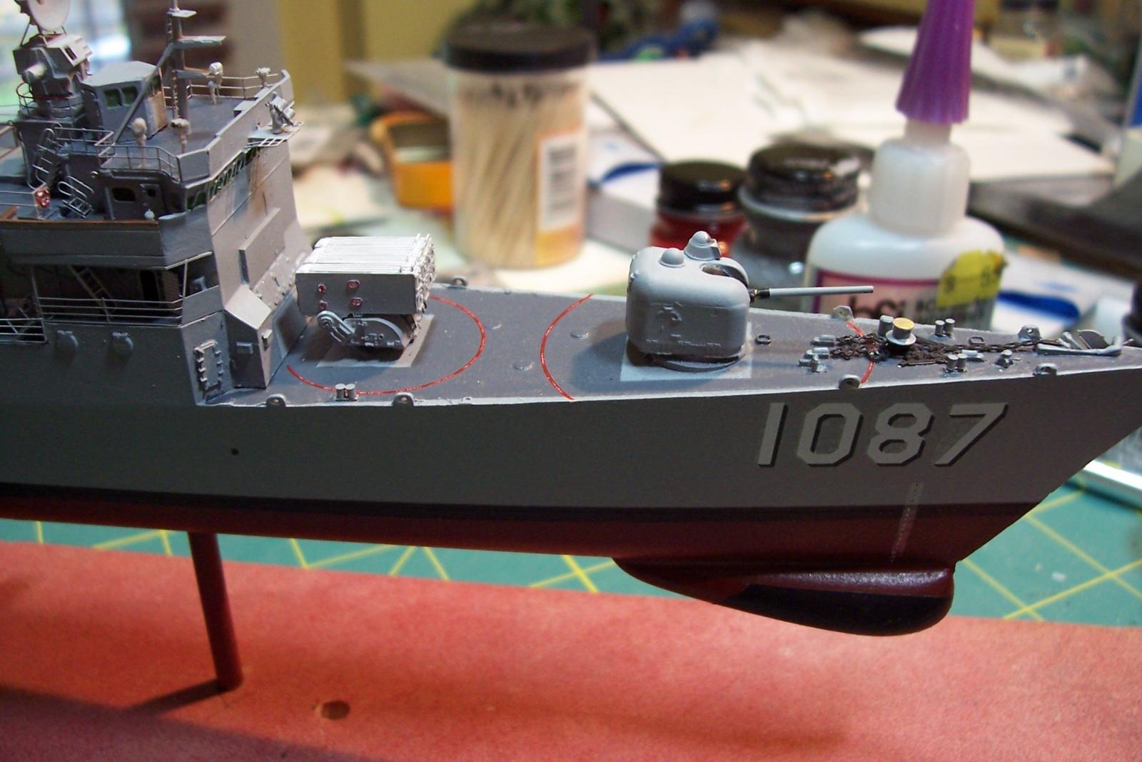
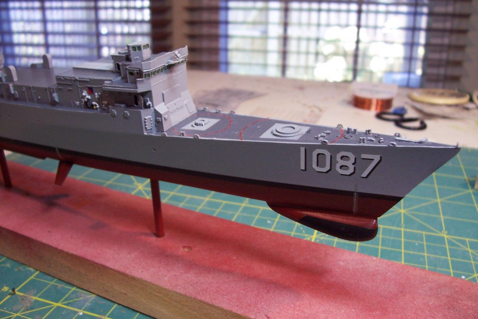
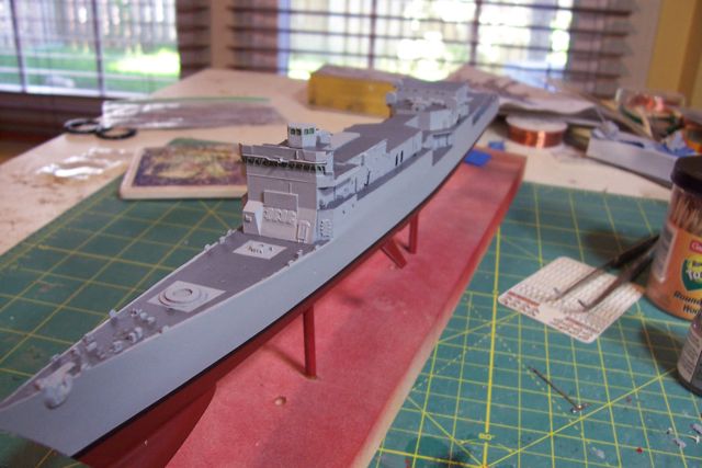
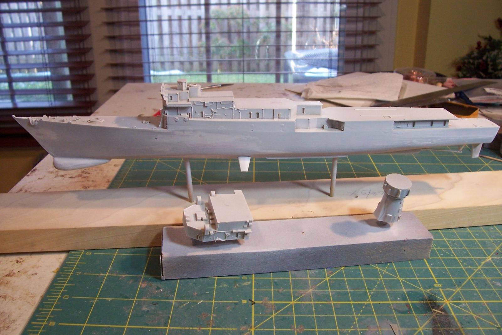
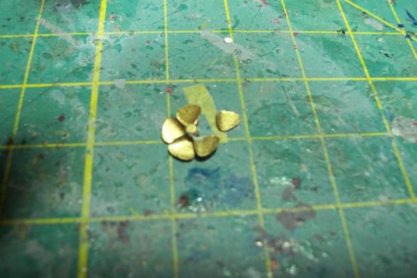
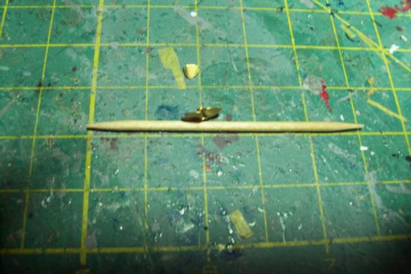
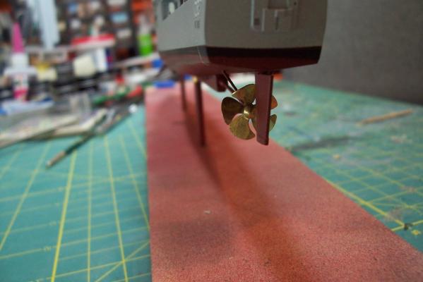
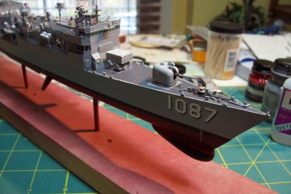
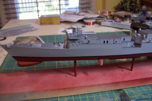
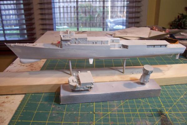
Foc’sle & Prop The only real gripe I have about parts from this kit is the prop. It comes on it’s own sprue and each blade has a pour ridge on it’s backside which takes over an hour of careful work with an X-Acto to remove. Once they are off the results are underwhelming - the prop right-handed vice left-handed, it is noticeably under scale and there is almost no pitch to the blades so it looks like a little pressed flower hanging on the end of the shaft. I tried cutting off the blades and reattaching them with more pitch angle but it was hard to get the spacing equal and the result was as bad as the original. I ended up springing for a set of cast brass props which look much better. I added the ground tackle, gun and ASROC. The ASROC launcher is an after-market item from Veteran Models that I already had on hand, although the kit one was quite good I’m on hold awaiting the arrival of the case and display base because I want to transfer the model to it’s permanent base before adding the main deck lifelines in order to avoid messing them up. Hopefully it will be here in the next few days.

- 22 replies
-
- 7
-
-
- kirk
- orange hobby
- (and 4 more)
-
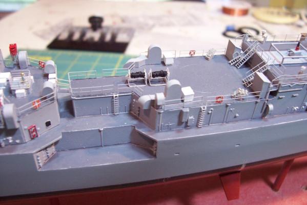
Upper deck details The superstructure is just about done at this point. The boat davits were more complex than I thought they would be - a ton of tiny PE detail, much of it buried underneath other pieces, just about every cable and pulley is included. About all that is left to do is detail the foc’sle, fantail and flight deck nets.

- 22 replies
-
- 8
-
-
- kirk
- orange hobby
- (and 4 more)
-
I was a little surprised to see this build log awaken again from deep sleep but thanks for the kind words Brian, tomasg and especially to Tim, the old FRAM sailor.
- 144 replies
-
- 3
-
-
- basilone
- BlueJacket Shipcrafters
- (and 2 more)
-
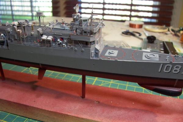
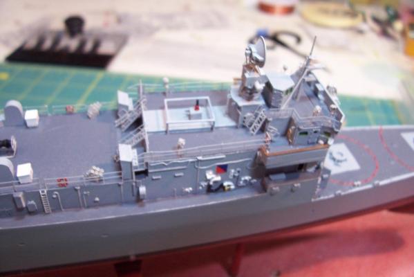
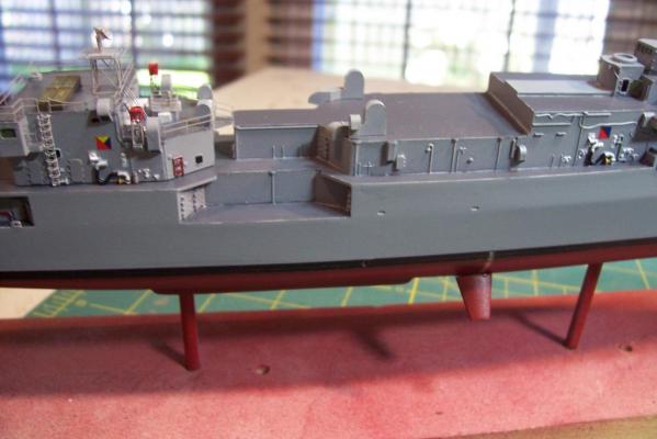
Upper deck details At this point most of the details on the 02 level and up have been added. The pelorus’, signal lamps, “Big Eye” binoculars and the SRBOC launchers are after-market items from Veteran Models. The bridge railings and the HF antenna coupler with its "fence" aft of the FC director are scratch. Next up will be rigging the boat davits.

- 22 replies
-
- 8
-
-
- kirk
- orange hobby
- (and 4 more)
-
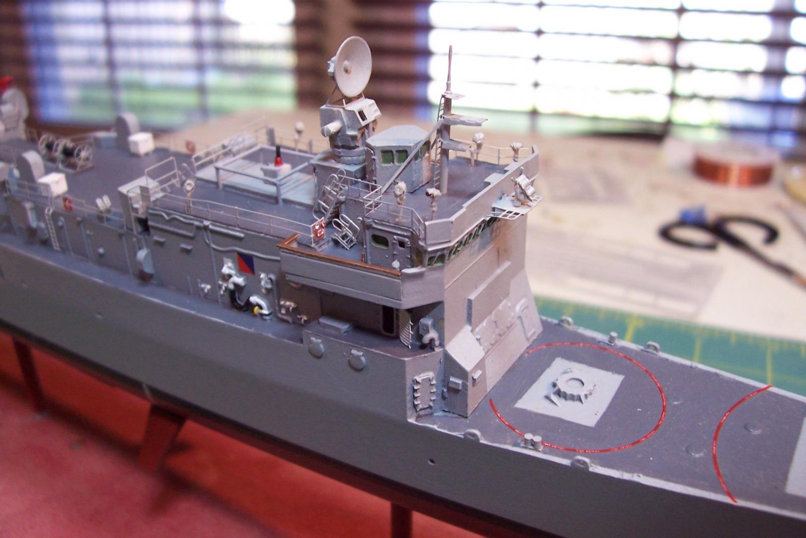
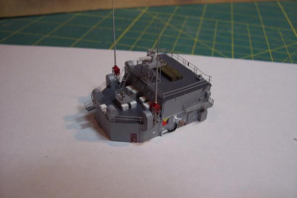
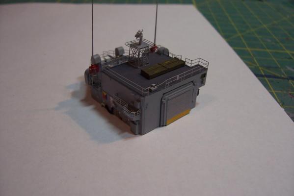
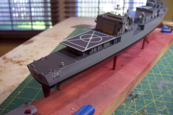
Helo Hanger Painting and detailing the hanger took a little longer than I had planned but at least it is done. The 2 HF whip antennas are just dry fitted on their stands which is why they look a little out of kilter, I’ll glue them in at the end of the build so they are not in the way while rigging the wire antennas. Although it’s hard for me to scratch details at this scale I couldn’t stop myself from adding a few: the UHF SATCOM antenna (although its tower was supplied - one of those head-scratchers about this kit) the binnacle for the after conn the storage boxes for the spare helicopter blades the glide slope indicator Most of the hull decals have been added at this point. The decals are good quality. I cut up the flight deck markings into sub-pieces because it seemed a bit much to try in one go.

- 22 replies
-
- 9
-
-
- kirk
- orange hobby
- (and 4 more)
-
Thanks for the looks and kind words. Canute - thanks for the tip about cleaning resin. My hobby shop guy swore by Diet Coke but it didn't do the trick - I'll remember yours
- 22 replies
-
- 3
-
-
- kirk
- orange hobby
- (and 4 more)
-
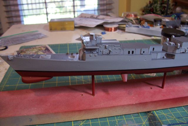
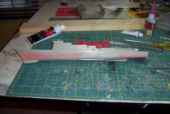
After being down for a couple of weeks due to some "kid crud" brought home by my wife the school teacher I was about ready to spray the big parts of the model but had to find a part for my air compressor but I finally got it done. It was a bit of a learning experience. The paint & primer stuck fine to the hull but on several areas of the deck and vertical surfaces it came away in sheets. Apparently all the fitting work involving sanding on the hull left enough "tooth" for the primer to adhere to but the other areas were just too slick. After some light sanding where the paint came off I tried again with better results. Wish I had known that before all of the masking but at least I do now. I'll be doing some of the painting of the details that are cast onto the superstructure and then start adding the doors and other PE. For anyone thinking about buying this kit it is a bit of a mixed bag - what they include is very detailed but obvious items are left off, kind of like it was designed by a committee with everyone doing their job right but no one making sure everything was farmed out to some one. Some bulkheads have cables cast into them, but not all, there are no firestations or hose racks included, etc. It is still the best FF kit out there but a little research and aftermarket PE and scratch building is still needed - more than should be at this price.

- 22 replies
-
- 9
-
-
- kirk
- orange hobby
- (and 4 more)
-
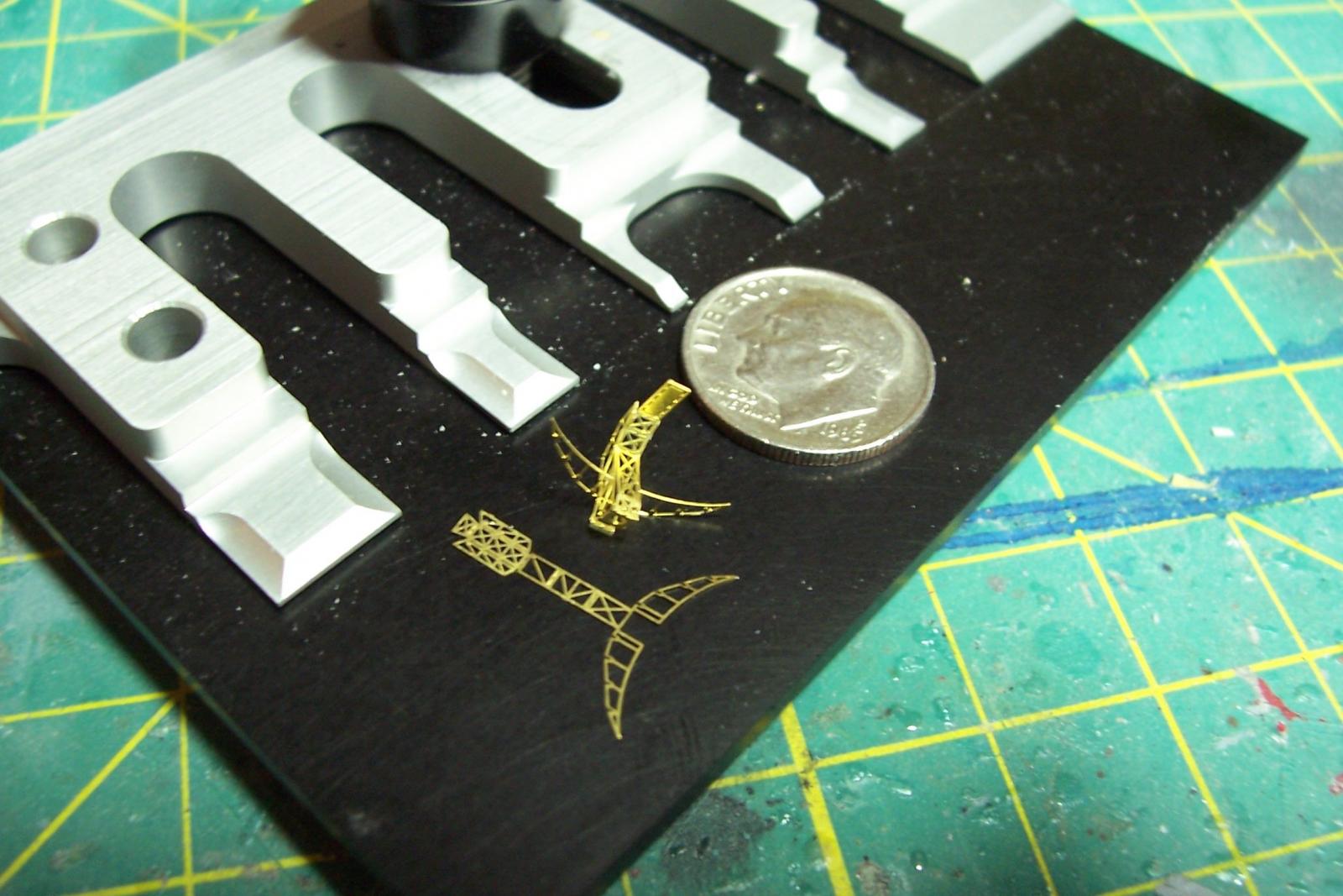
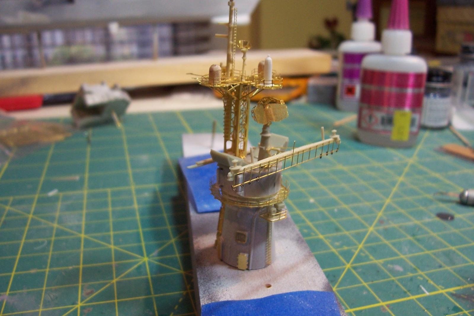
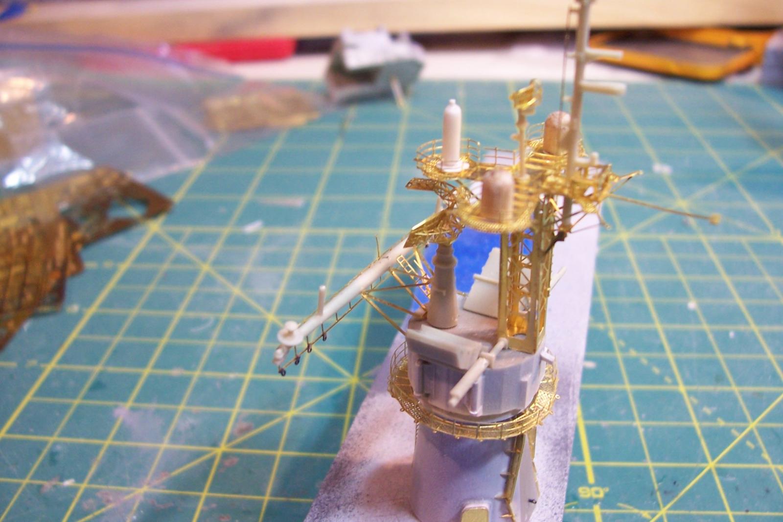
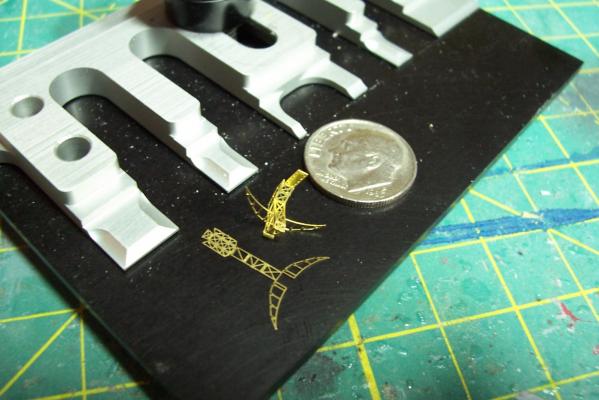
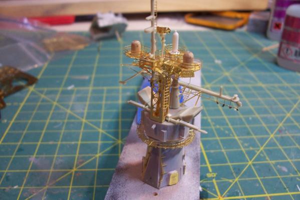
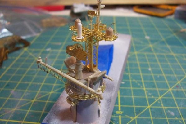
Photo Etch This kit has a LOT of PE. It is incredibly detailed but also very thin and will not stand up to more than one or two attempts to fold it before that junction gives way. Some of it is very tiny, including 2 sets of counter rotating propellers for the torpedo on the ship’s helo, they are less than 1mm in size. Some of it is frankly over-engineered, for example the railings on both levels of the MACK have tiny extensions at the bottom of each stanchion which are supposed to fit into corresponding tiny holes - hard enough to do in a straight run but with multiple bends in is simple impossible. I ended up filing them off and even cutting the railings into smaller sections to make them workable. The kit instructions have NO text and very few sequential “how to” drawings of how to assemble some very complicated PE assemblies so they require a lot of study before snipping the first piece. Bottom line: I recommend that you not attempt one of these Orange Hobby kits unless you have a fair amount of PE experience above and beyond mere railings. These kits are pricey and you may easily find yourself in over your head with little hope of getting replacement parts to fix mistakes. The MACK (mast & stack) Here’s an example of the PE I was referring to, these are the first 3 pcs of the air search radar antenna, 12 more will be added before it is done: Here is the completed MACK which took me about 10 hours of work over 5 days, usually in 10 minute increments so I didn’t lose focus with the tiny parts. There are just under 90 pieces, almost all of which are PE (the wood and plastic domes are scratch additions to reflect a superseded EW system whose antennas stuck around for years after the system was replaced):


- 22 replies
-
- 12
-
-
- kirk
- orange hobby
- (and 4 more)
-
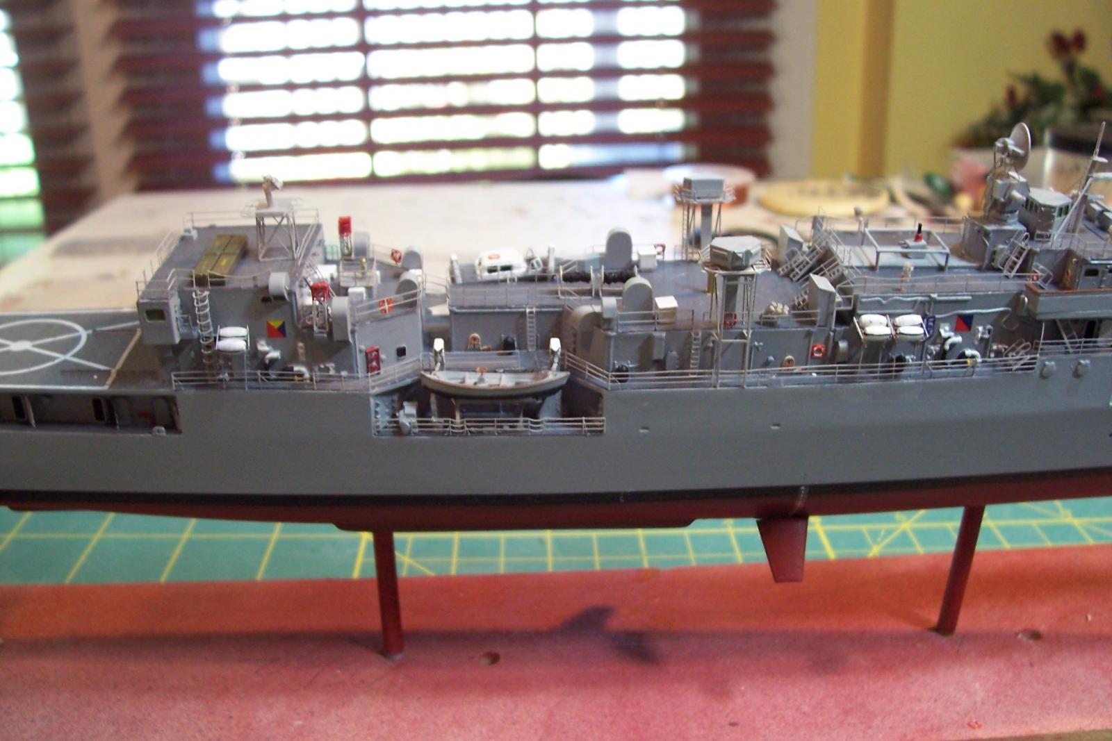
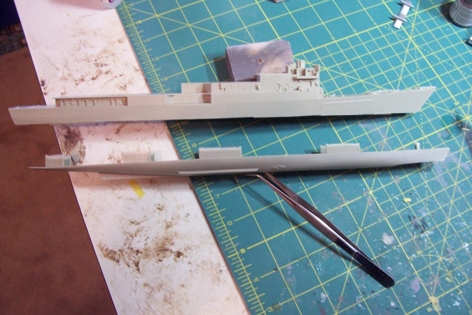
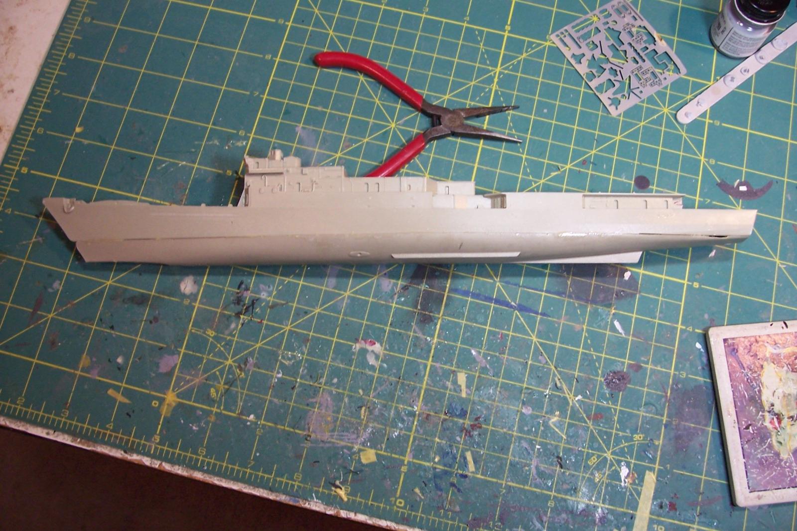
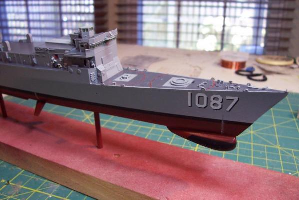
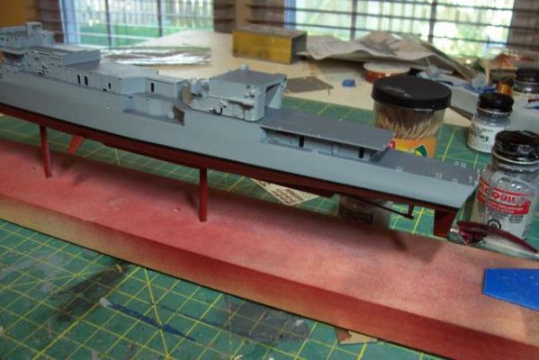
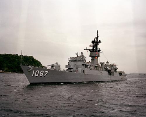
I'll be using Orange Hobby's USS Robert E. Peary 1/350 resin kit to build a model of my first ship, USS Kirk (FF-1087), a Knox - class frigate I served on 1979-81. The kit comes with a boatload of PE ( more about that in the next post), a few machined metal parts and resin for the bulk of the model. The decal sheet has the name and hull #'s only for the Peary so I will use GMM decals. There are 4 main resin pieces; upper and lower hull (in case you want to build a waterline model), the MACK (mast and stack structure), and the helo hanger. I was not real happy with the fit of the upper and lower hull, given the price of this kit. I had to remove the moulding plugs from the upper hull but I left on the lower ones to provide more strength. There were several areas where the lower hull was too wide or too narrow. I built up the narrow areas with strip plastic and then used Bondo's glazing putty where needed. It took a lot of sanding and several iterations of priming, puttying and sanding before things were shipshape. I forgot to take a photo before I started removing the "hurricane" bow bulwarks which were added to KIRK after my time onboard. You can still see some residual parts of it - it was very easy to remove with an X-acto knife. I'll be assembling the MACK next, because as you will see it is the most complicated part of the build, and since the chances of getting replacement parts from a Chinese company are slim, it is also the most risky so if I end up having to trash the build at least I will find it out before investing a lot of time on the simpler parts.


- 22 replies
-
- 10
-
-
- kirk
- orange hobby
- (and 4 more)
-
Wow! That is one of the smoothest and most uniform paint jobs I've seen on any naval model. Well done!
-
Thanks Mark, Yes I was surprised with the differences, the cast-on detail, the detailed instructions, the amount of PE and even the weight (the old model feels like it is solid metal). My next build will be a kit from the same manufacturer of a Knox class frigate I served on then it will be back to sawdust and splinters.
- 24 replies
-
- 3
-
-
- gemini
- orange hobby
- (and 2 more)