schooner
-
Posts
743 -
Joined
-
Last visited
Content Type
Profiles
Forums
Gallery
Events
Everything posted by schooner
-
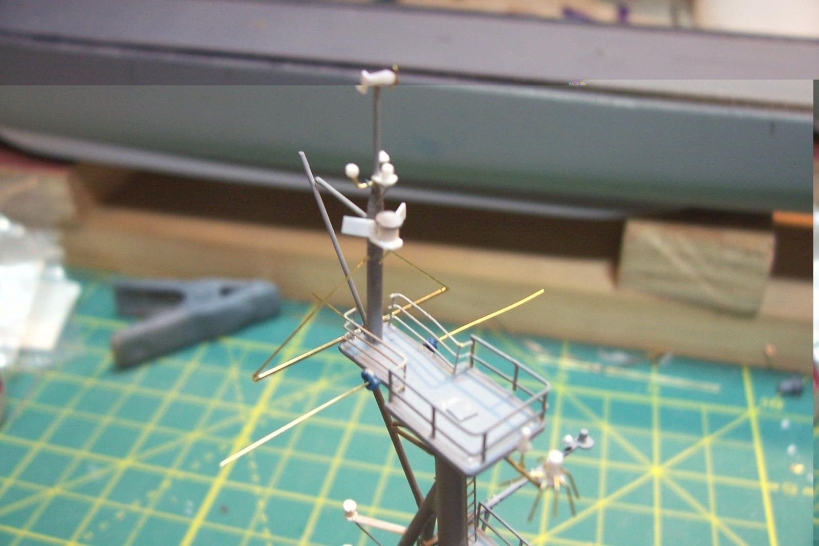
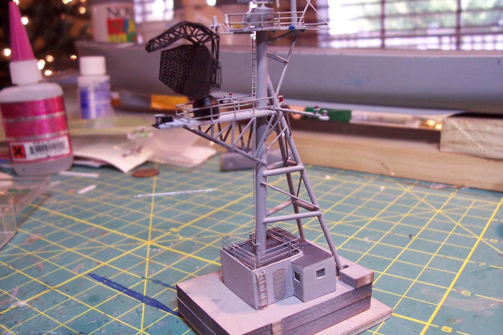
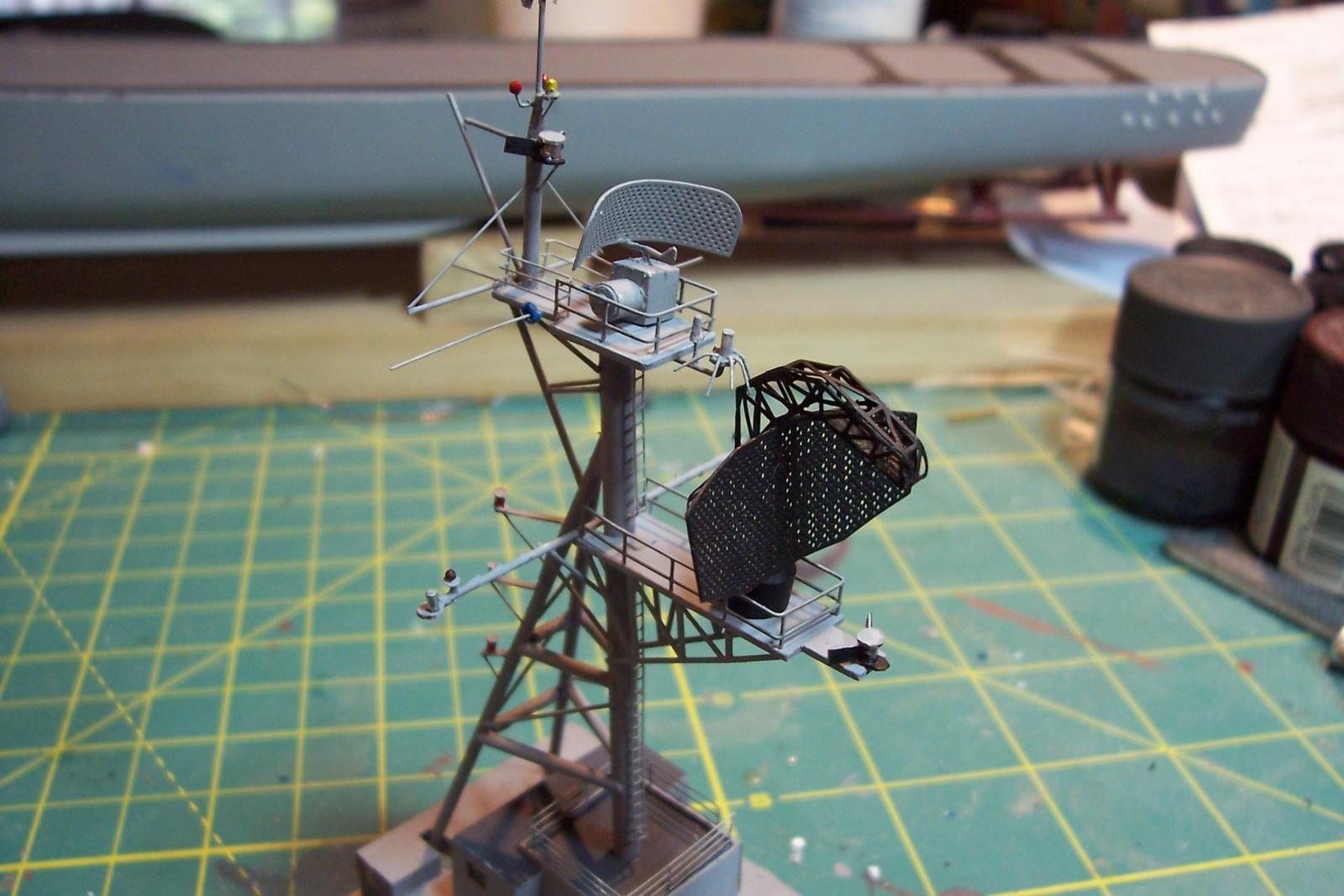
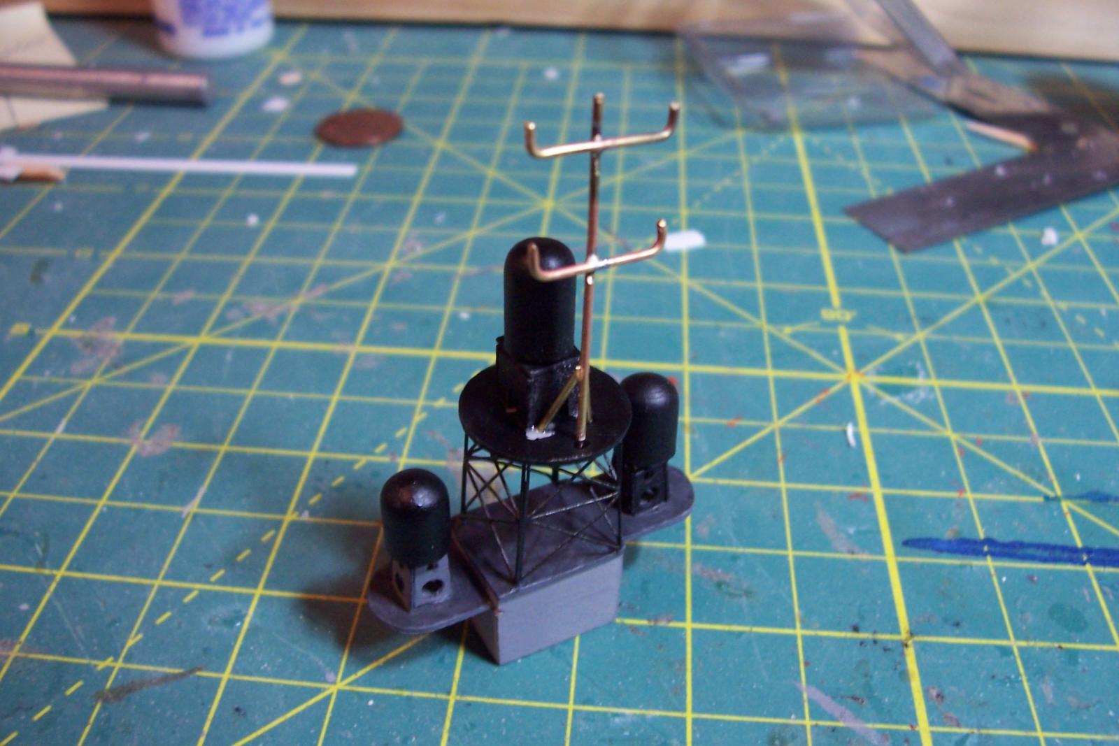
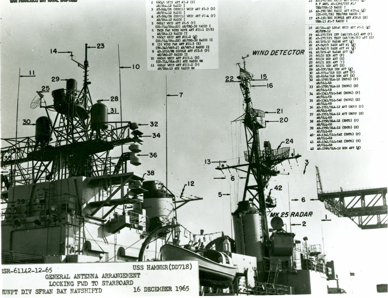
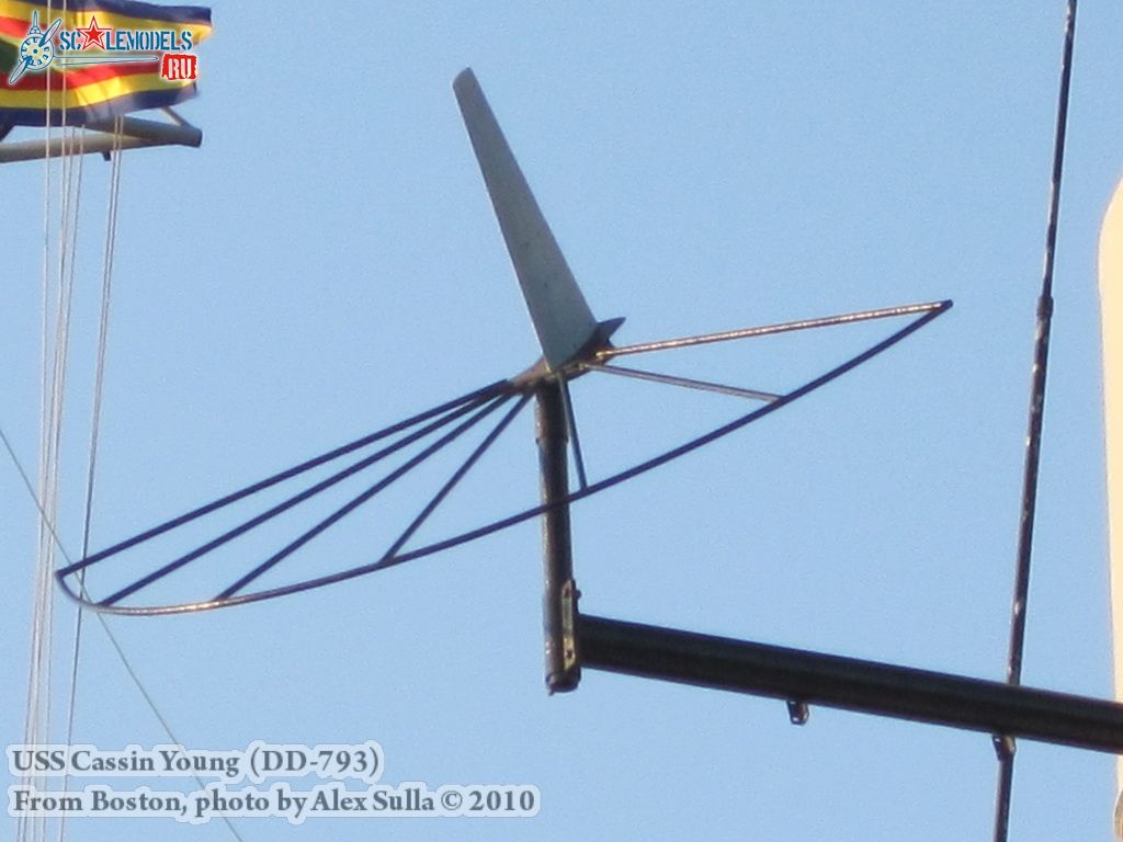
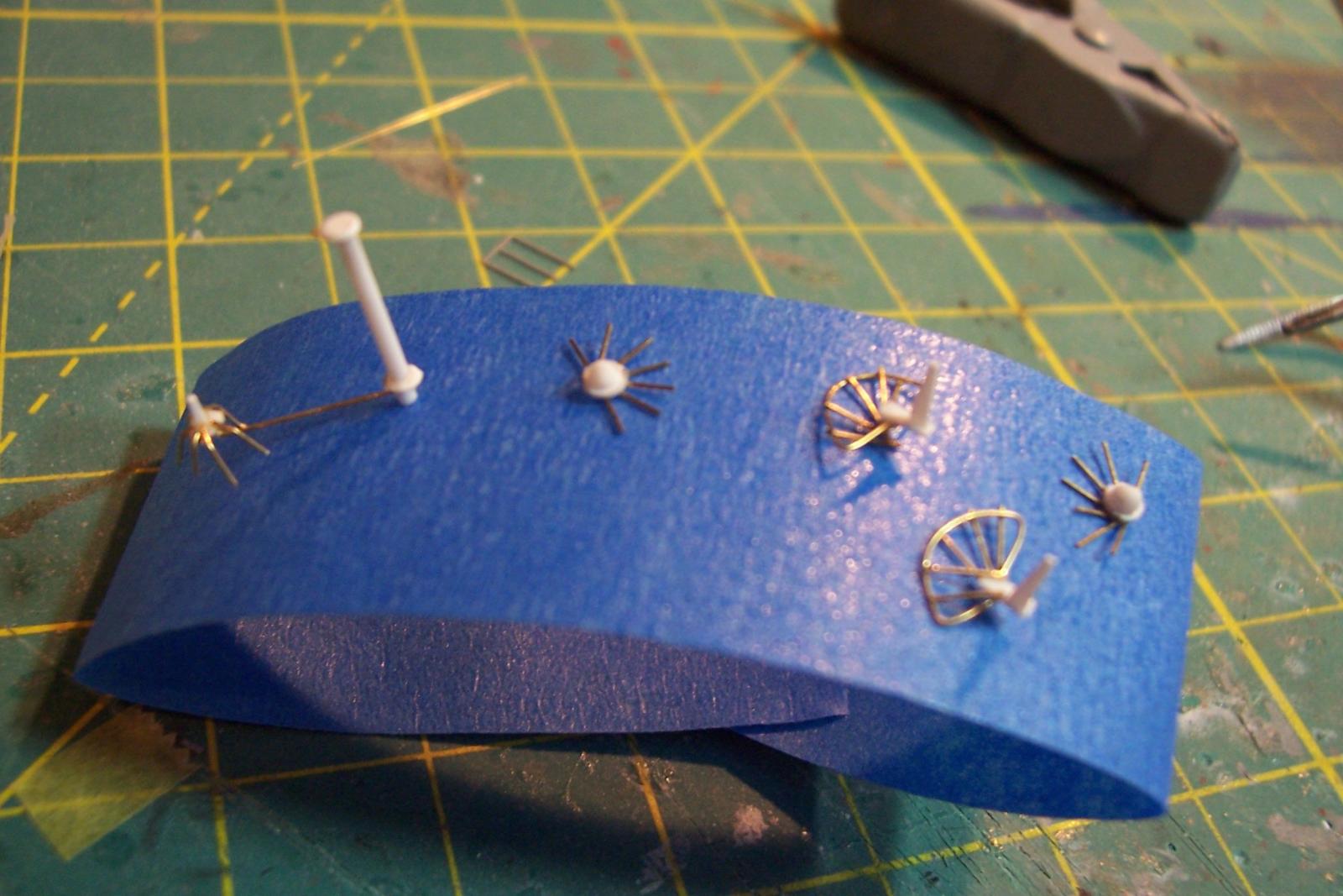
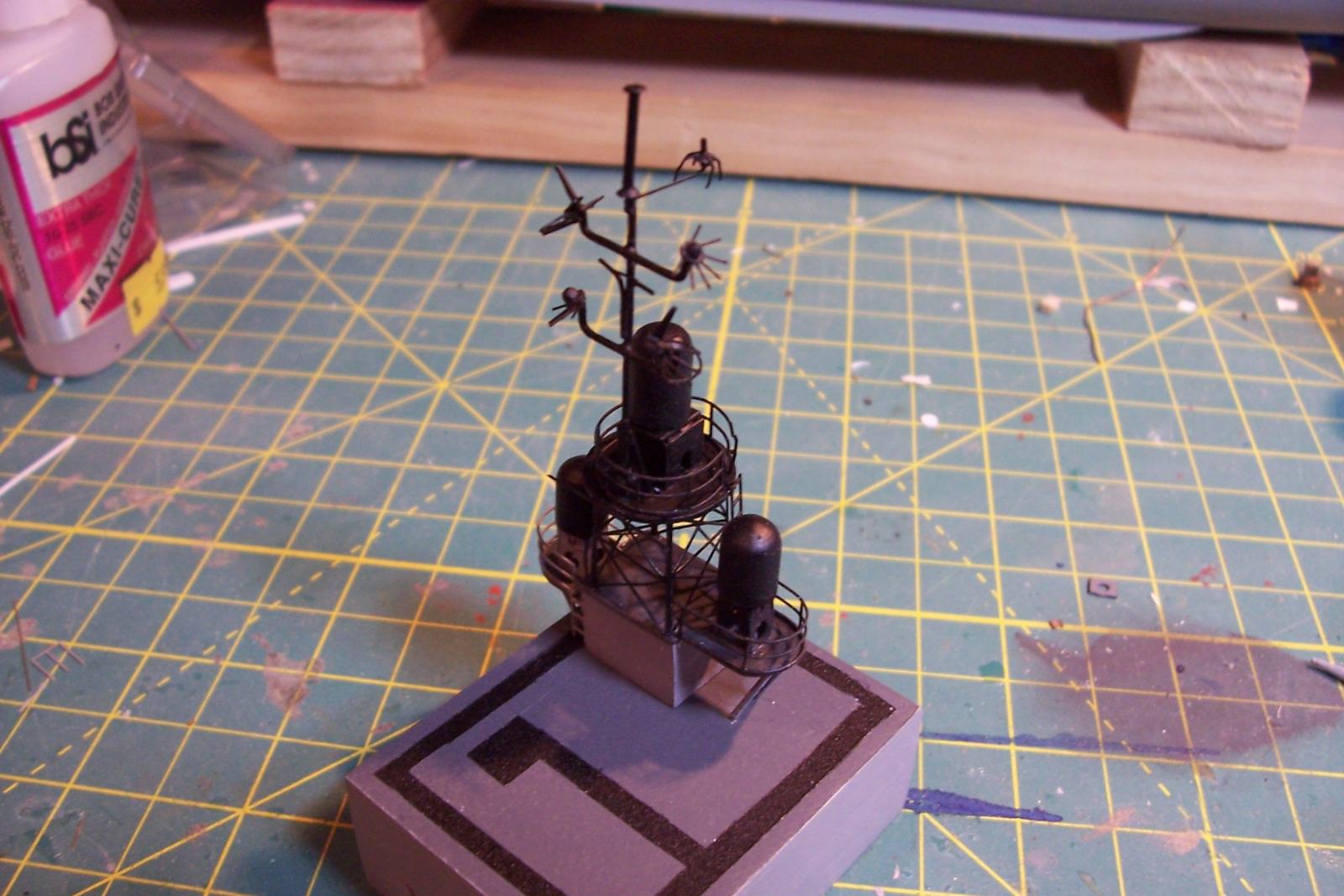
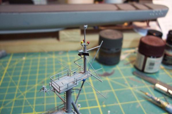
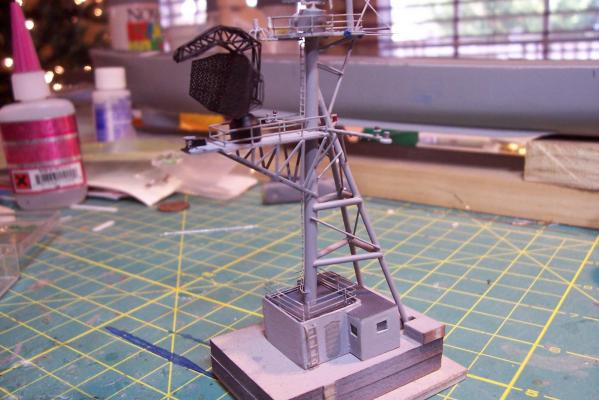
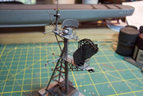
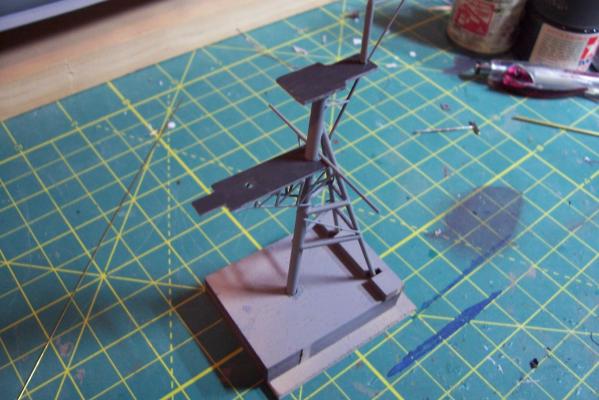
 Main Mast (cont) Details were fabricated out of brass wire and styrene: Here they are after painting, to include several small whip antennas, 2 UHF antennas, masthead and range lights (the ones with the sector shields), the lights on the outer yardarms are omni-directional blinkers for sending messages to several ships simultaneously at night, just inboard of them are the Nancy lights, which perform the same function except stealthily using IR. The other lights include the yellow ASW light and red aircraft-warning lights on the masthead, and the red and white man overboard /task lights on the starboard mast leg. The small yardarm is actually a antenna spreader for a fan antenna that will be anchored on the forward stack, and last but not least there has to be a wind bird (anemometer) at the mast tip: Here’s what it will look like with the radar antennas and the signal shelter / ops office: I prefer the look of black masts on naval ships and Basilone had a black mast starting in the late 60’s but at the time I selected to depict her (1966) it was still grey (albeit, the big black radar antenna defeated much of the camouflage effect). USN masts have alternated between black and grey several times over the last hundred years as the emphasis shifts back and forth between the tactically prudent and the aesthetically pleasing. About 15 years ago they went back to the more tactically prudent grey again.
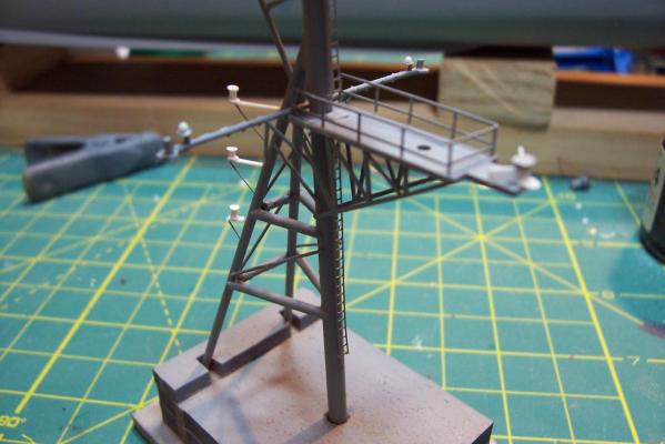


- 144 replies
-
- 6
-

-
- basilone
- BlueJacket Shipcrafters
- (and 2 more)
-
Great to hear from you again Patrick! Hope you will be posting again soon.
-
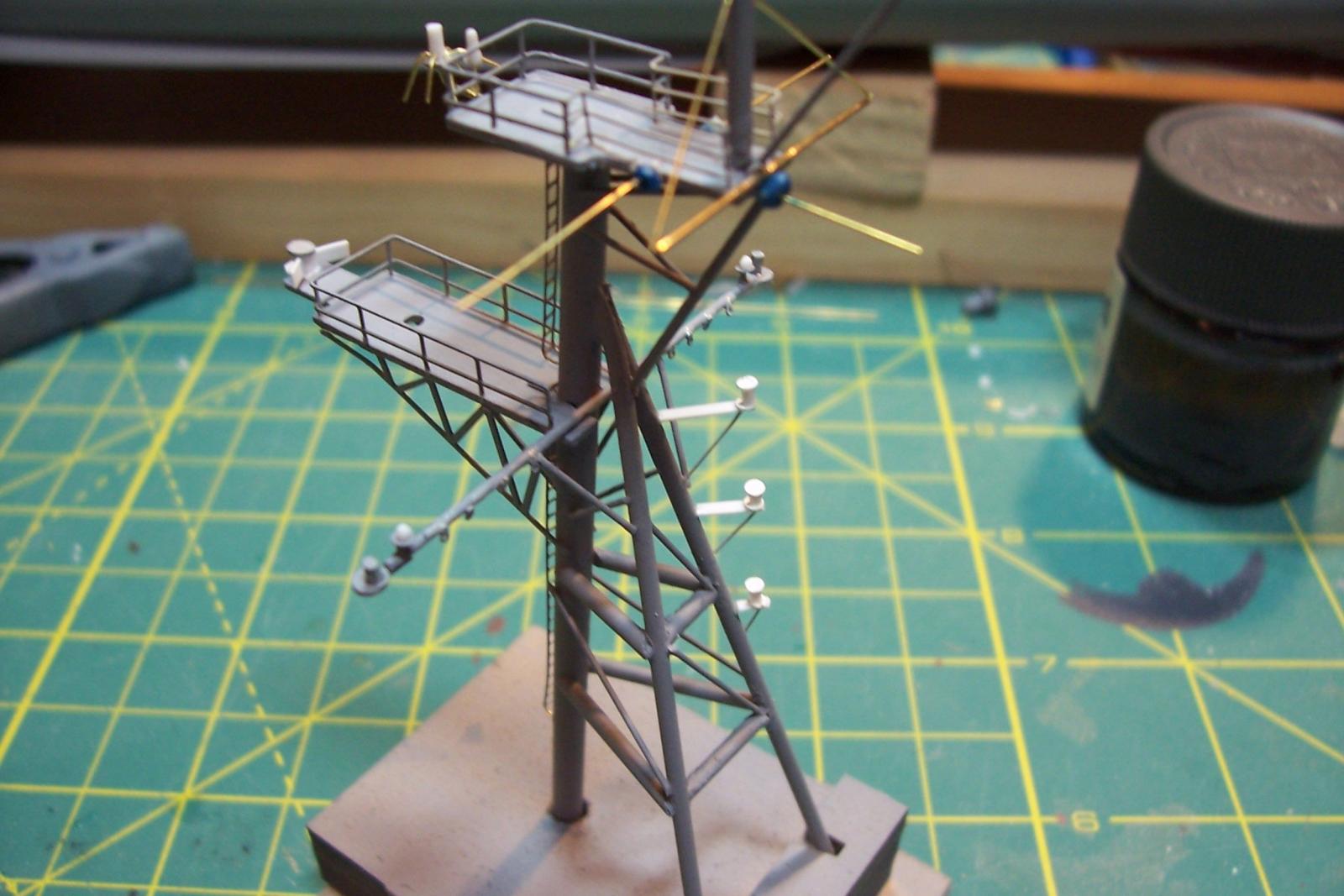
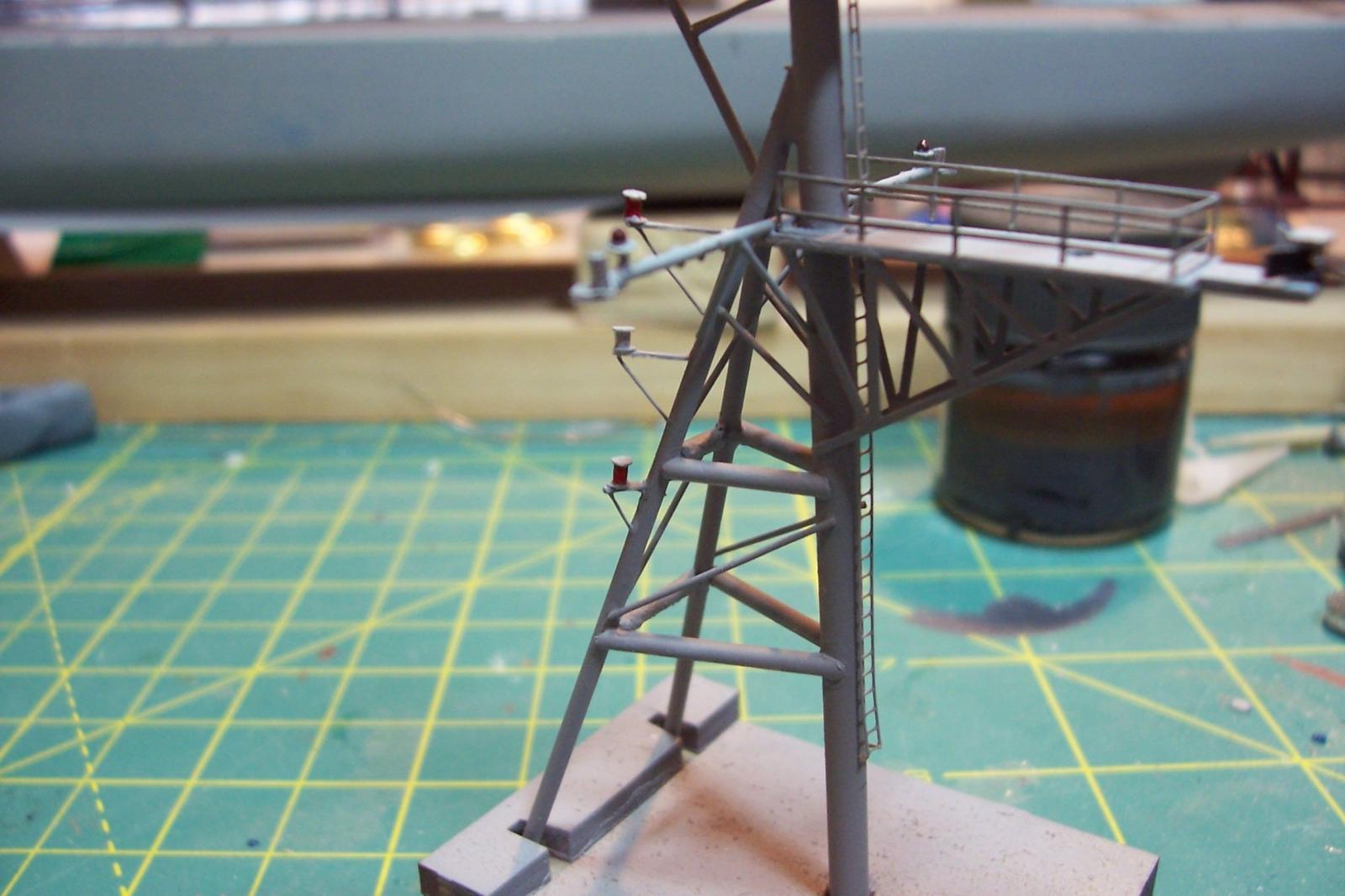
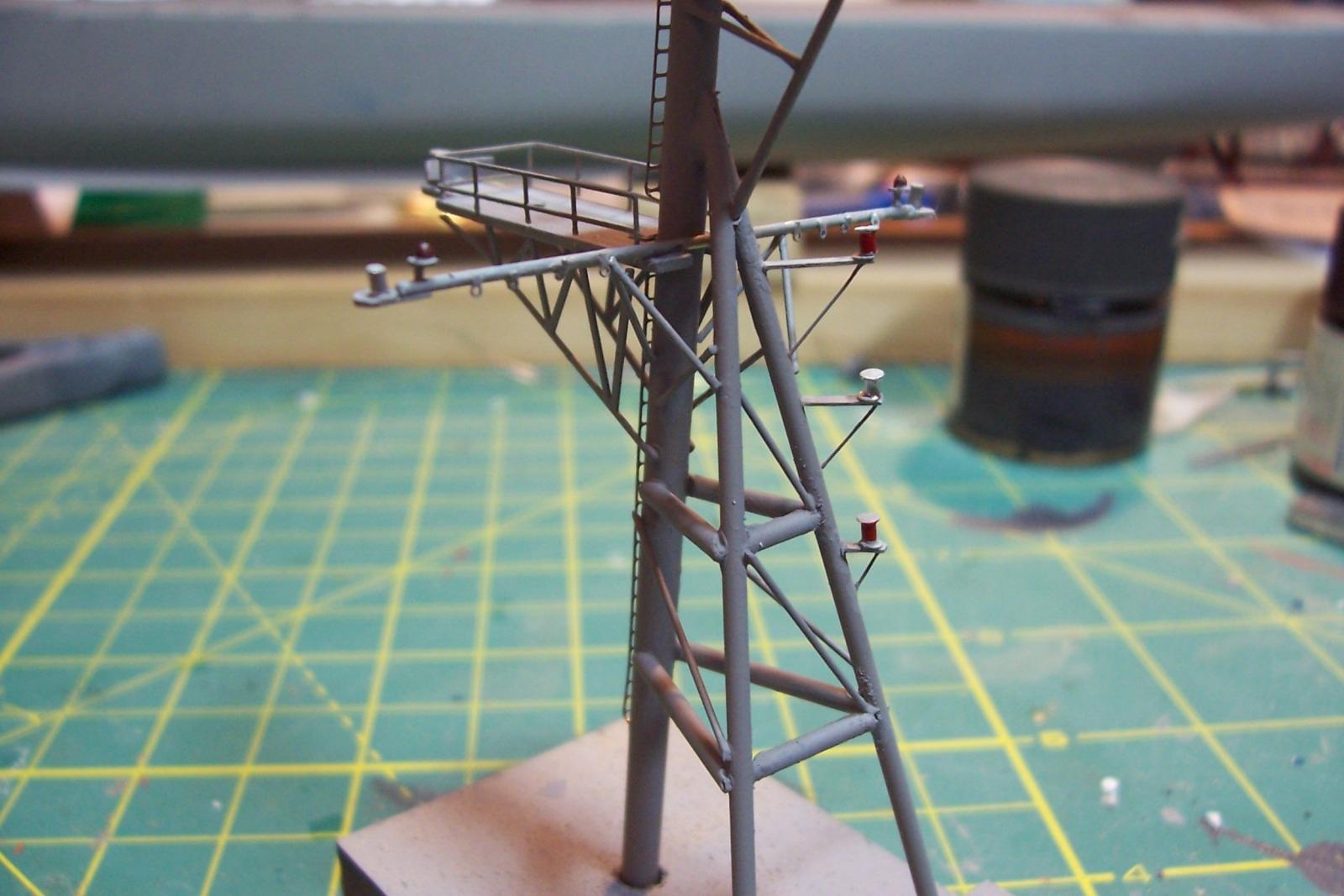
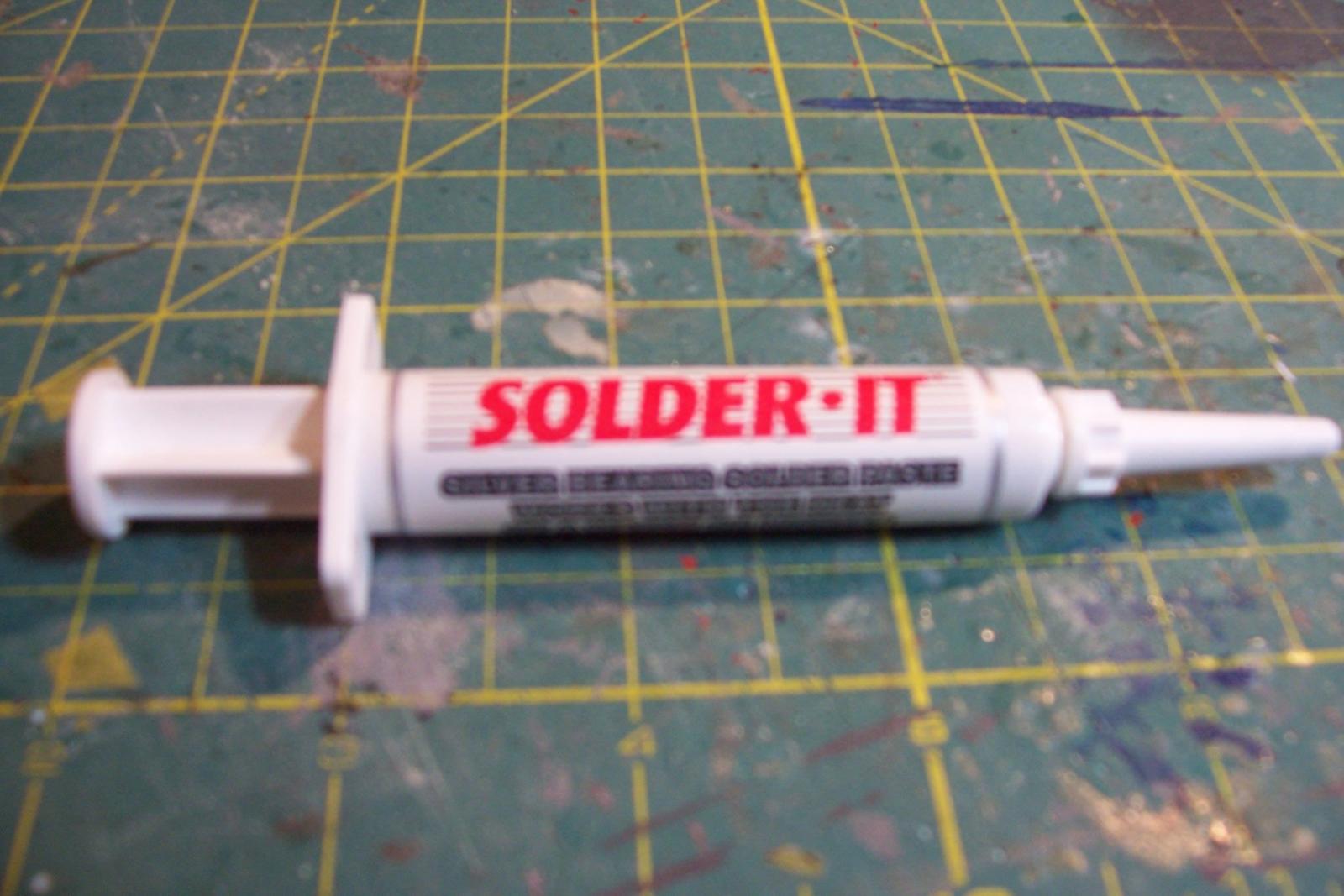
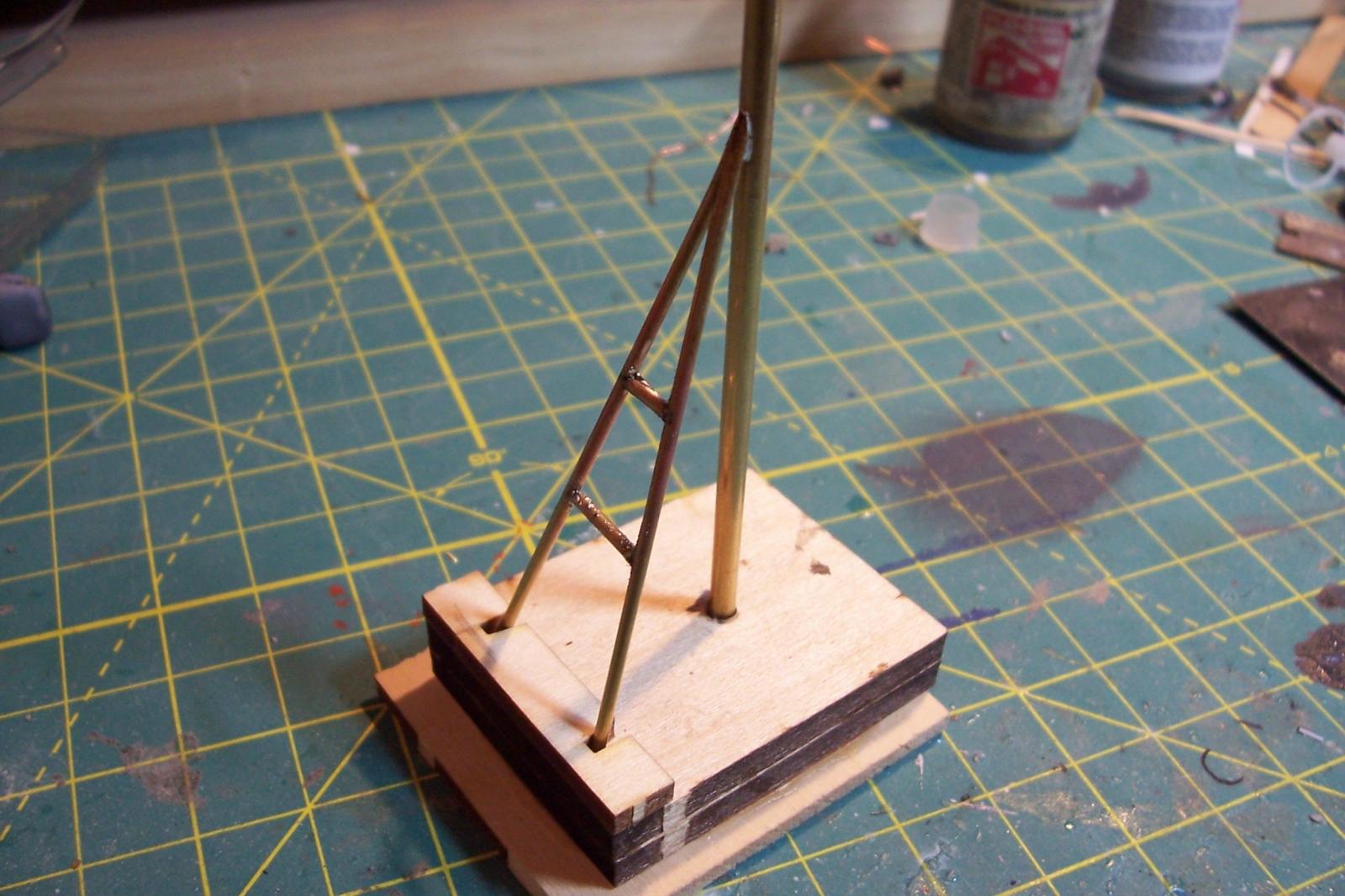
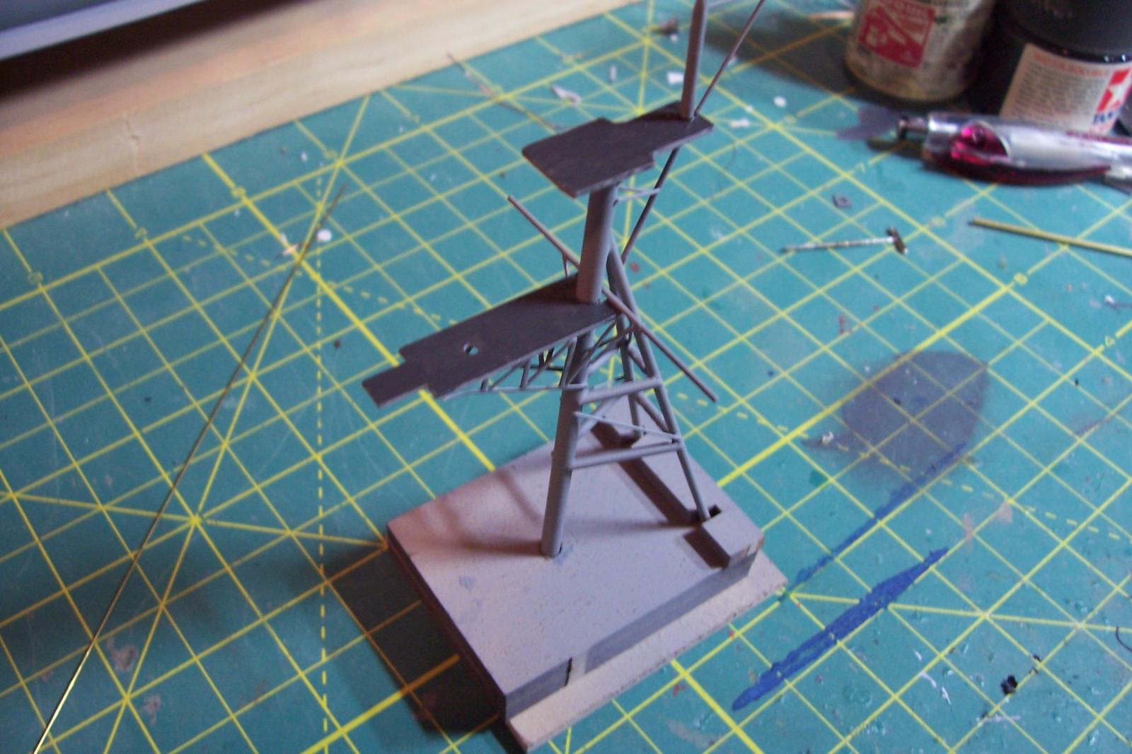
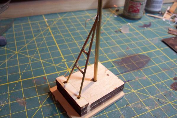
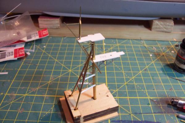
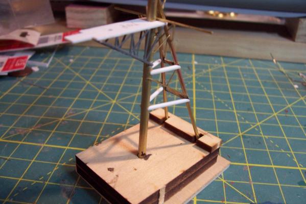
Main Mast The mast is fabricated out of brass tubing, rod, some PE and laser-cut plastic. I’m not great at soldering so I wasn’t looking forward to this part of the build but I did find something that helped a lot. This may not be news to anyone but me but they sell solder paste that has both the solder and flux combined in one. It goes on easily, you can easily control where you want it, it stays in place (unlike tiny pieces of solder), heats up quickly with a flame jet, doesn't run when it melts and has no slag that needs to be cleaned up. I don't know if it would work for high-temp soldering or how strong it is compared to other methods but it worked fine for this application. The kit provides a very handy jig that ensures that the 3 legs of the mast are properly spaced - very important since it’s proper location on the signal bridge places the 2 rear legs on the deck edge so there is no room for error. I recommend that you solder the 3 legs together and then test them on their final location before adding the rest of the stuff to the mast - you may have to re-do it like I did. The bottom of the jig has an extra piece of wood that I added to match the depth of the main leg’s hole on the model. Here’s the extent of my soldering - everything after this is glued. The plans call for the support braces to be made of .020, 1/32 and 1/16 brass rod - I did that except I substituted 1/16 plastic rod since is is easier to shape than brass. The upper platform was replaced with a wider piece to better accommodate the motor on the base of the SPS-10 radar. The following pix show the mast as per the kit plans except the railings have not been added to the platforms yet. My next post will cover scratch details.

- 144 replies
-
- 8
-
-
- basilone
- BlueJacket Shipcrafters
- (and 2 more)
-
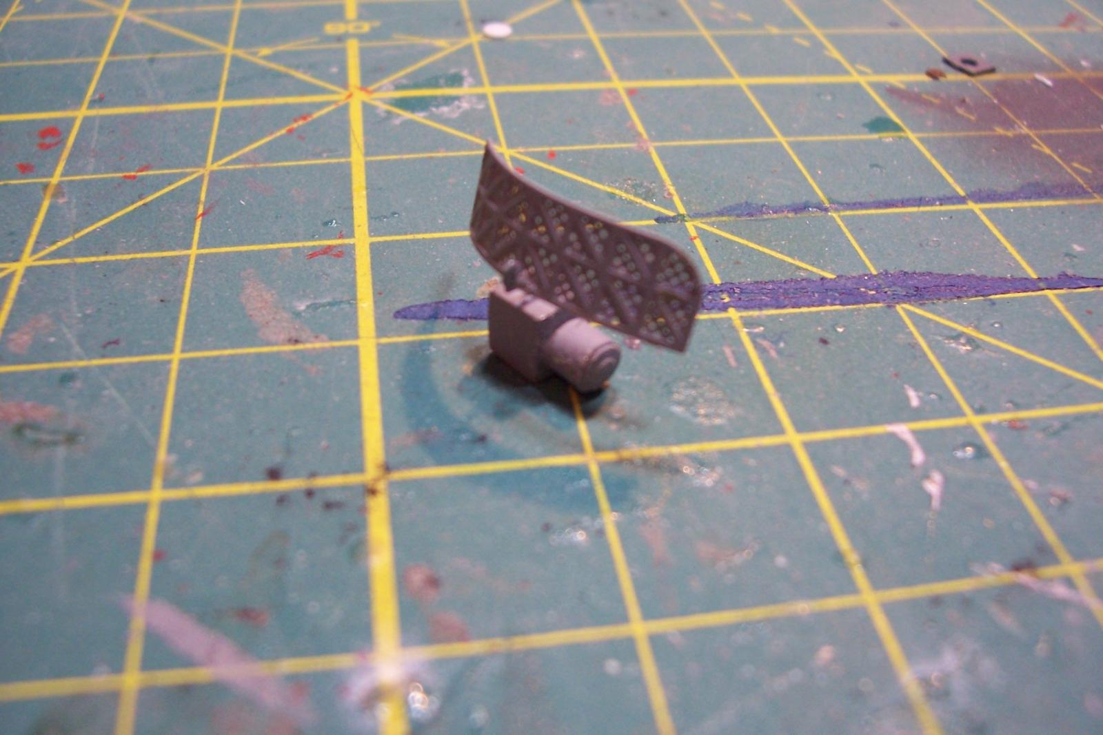
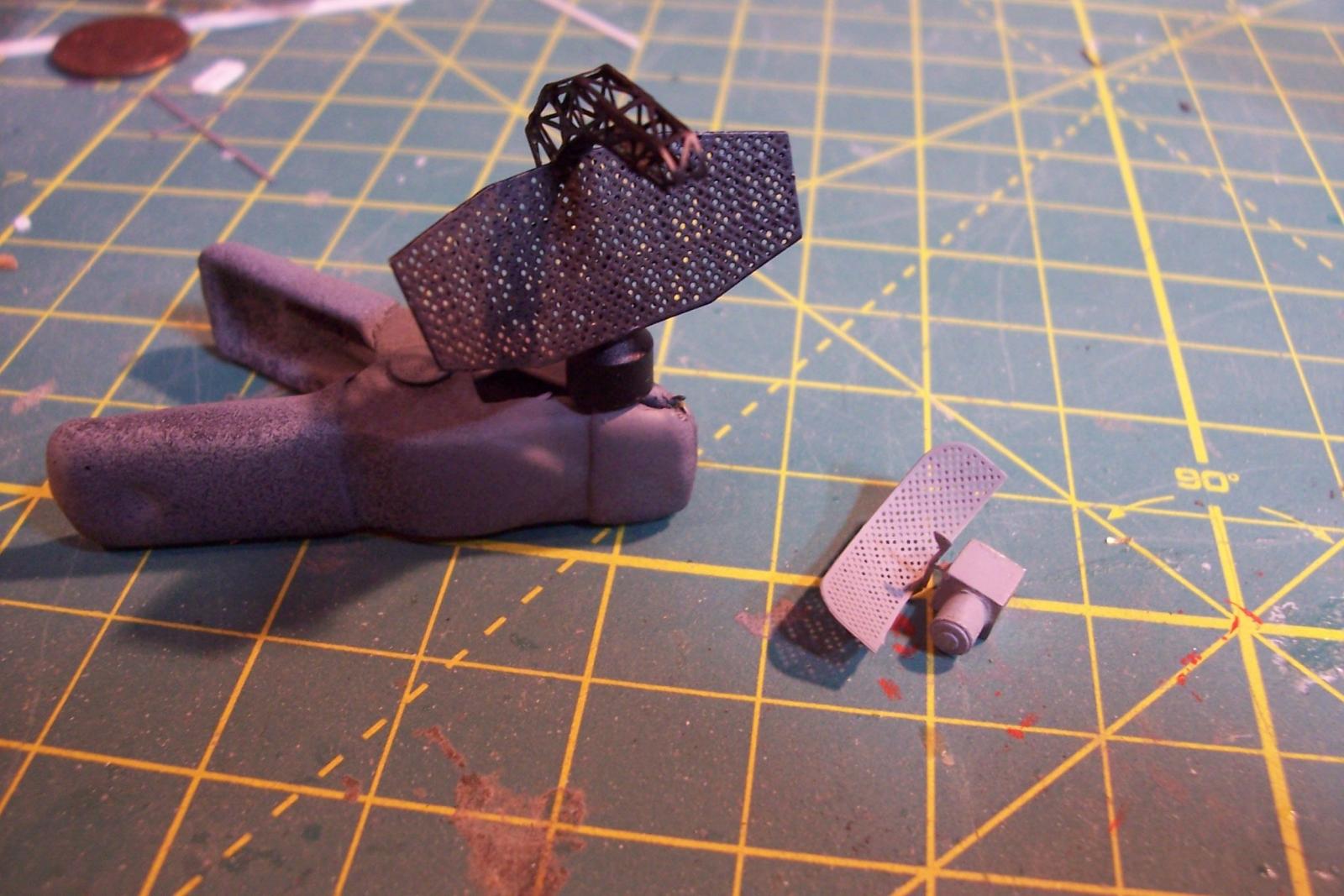
Thanks for the kind words Brian. The finished model may end up bad but at least it will be bad in a detailed way... The only good thing about having the Washington Redskins as my local team is that I can work on the model with the game on and not have to worry about missing any good plays, so here we go... Radar Antennas The FRAMs had 2 search radars; the SPS-10 Surface Search Radar and an air search radar. About half of the ships had the SPS-40 Air Search Radar, like Basilone, the rest had the SPS-29, the kit provides PE to build either of the air search radars. Here’s the PE for the SPS-40: The scorpion-shaped piece (the RF Feedhorn assembly) is folded into a crescent shape. My recommendations for anyone doing it are to 1) study some photos of the radar online so you understand how this will be shaped 2) take your time and carefully fold it first 3) then glue small sections at a time using medium CA with a spray of zip kicker when the pieces are aligned properly. Here’s the finished piece: The other 2 pieces are the array and the rear support structure (the mounting base is a piece of cast metal). The array is given a gentle cure bend into a parabolic shape and then the support piece is glued to the back. The instructions don’t mention it, but the rear piece should have it’s center section removed (after it is glued in place) so that the back of the array rests against the crescent piece discussed in the previous paragraph. Here are the 2 pieces glued together: The SPS-10 is similar but much simpler to assemble. Here’s the finished assembly: Here’s the finished and painted radars:


- 144 replies
-
- 8
-
-
- basilone
- BlueJacket Shipcrafters
- (and 2 more)
-
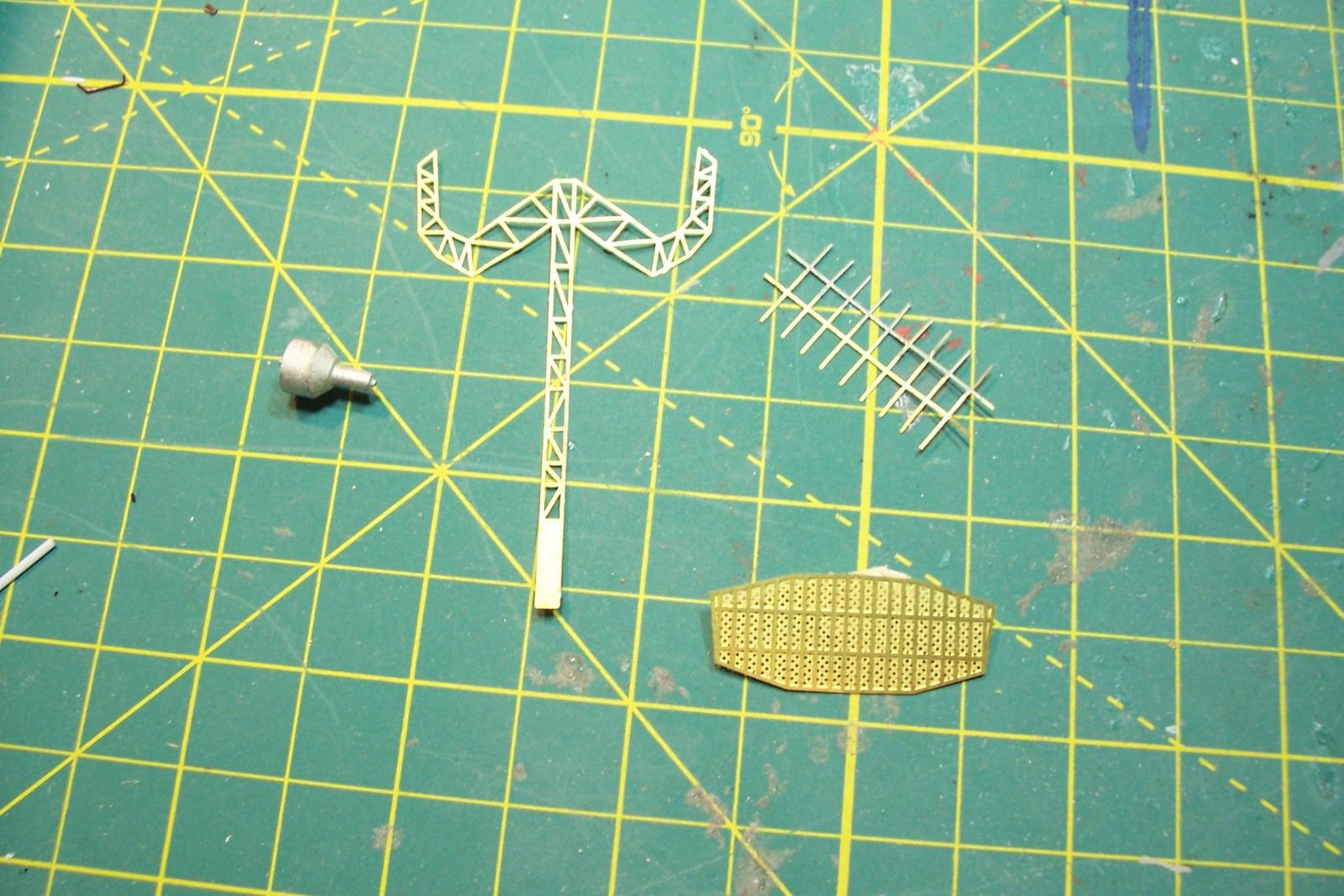
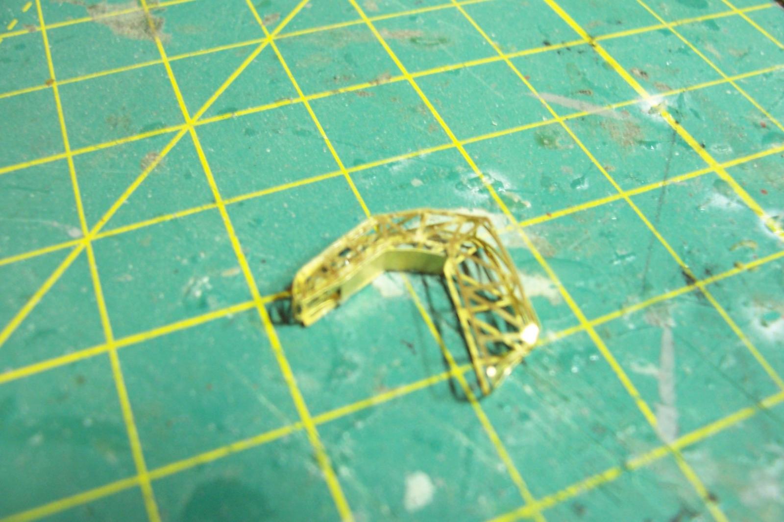
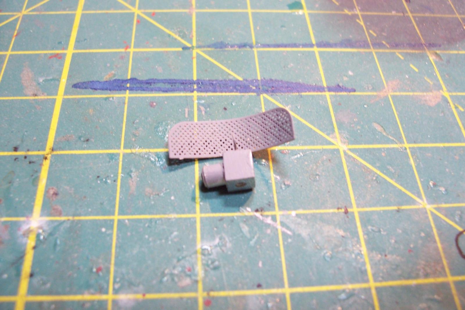
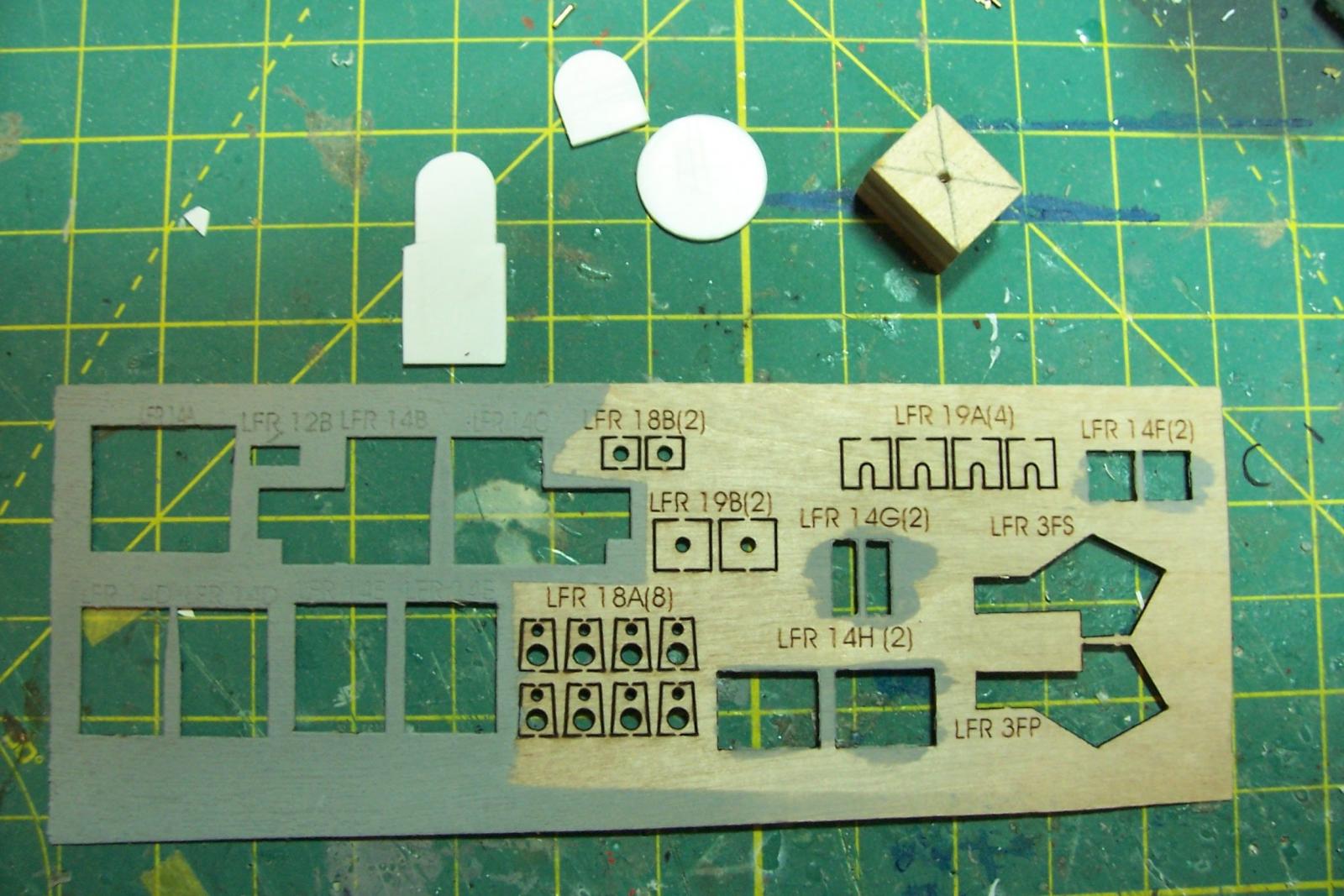
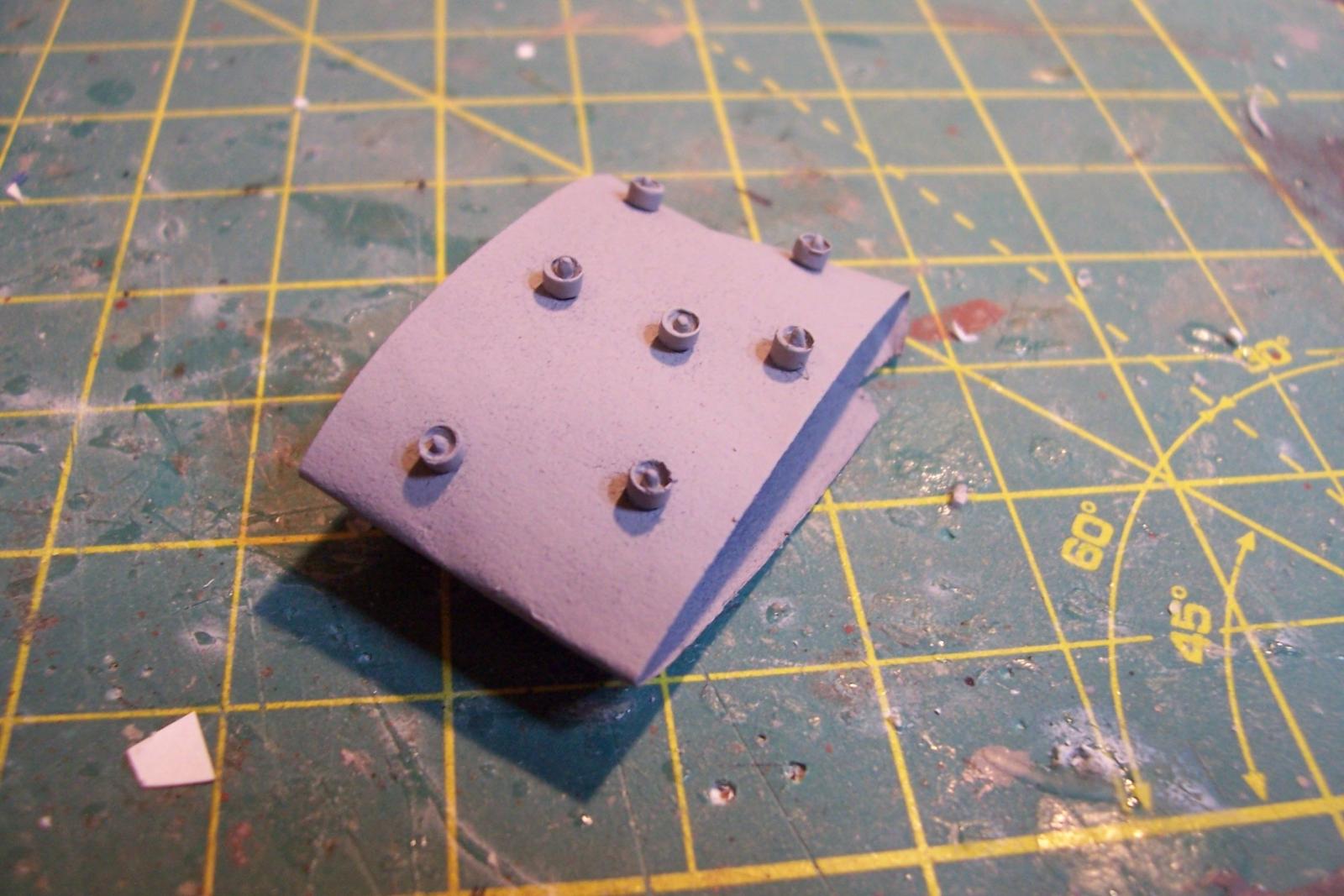
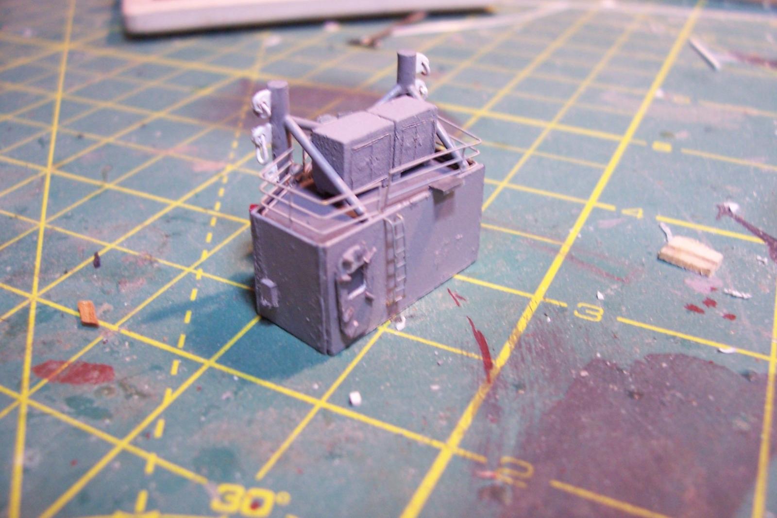
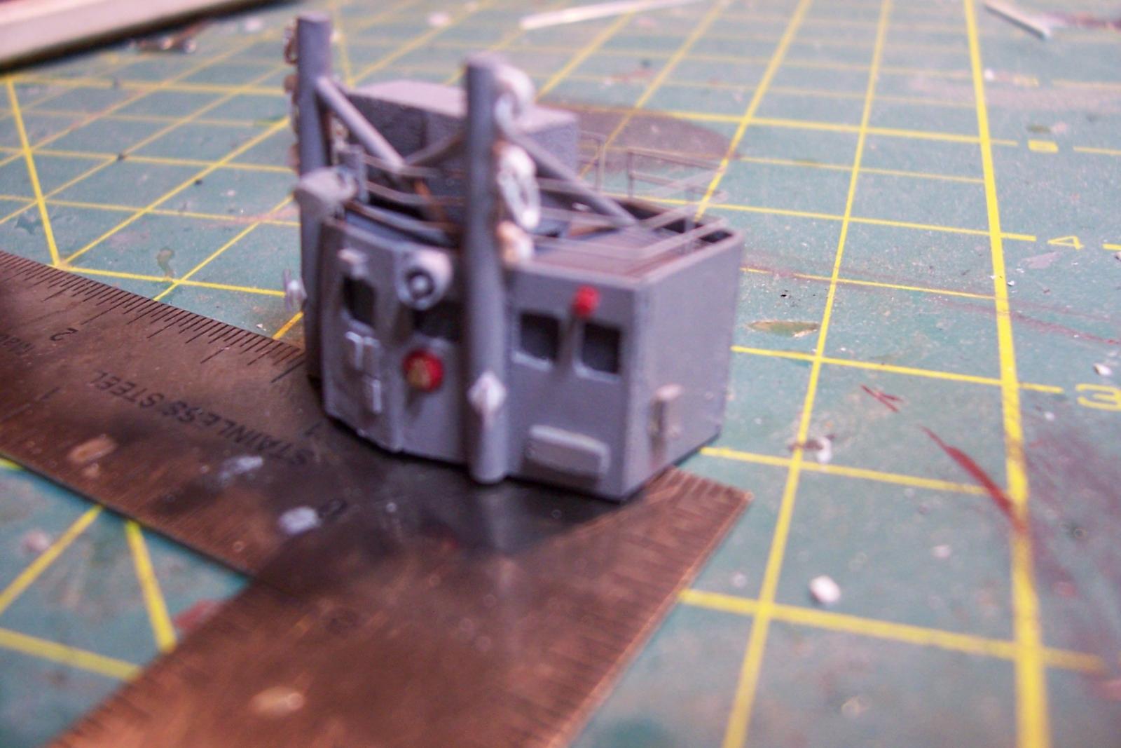
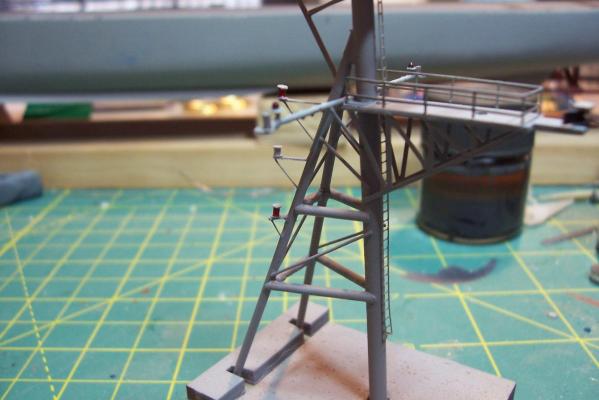
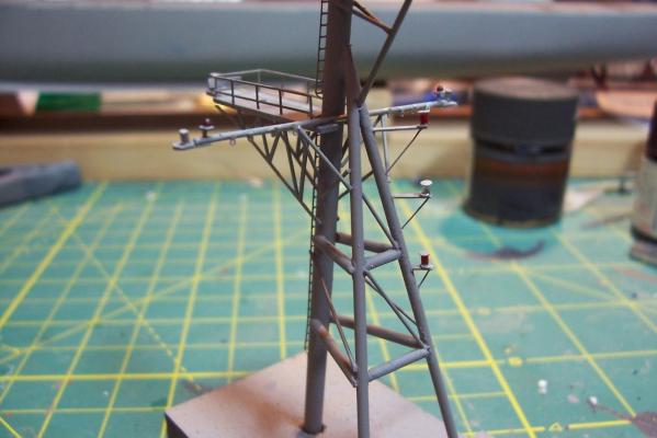
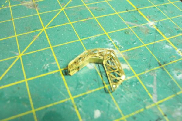
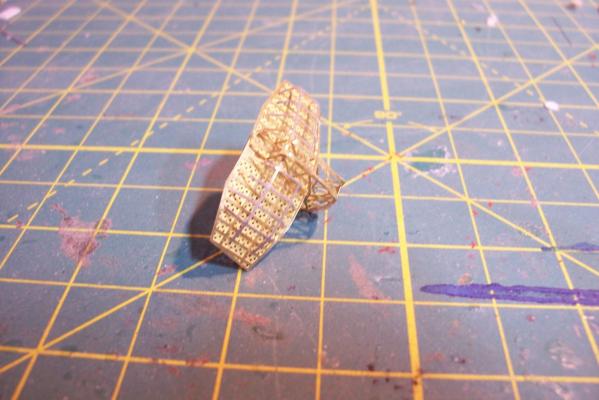
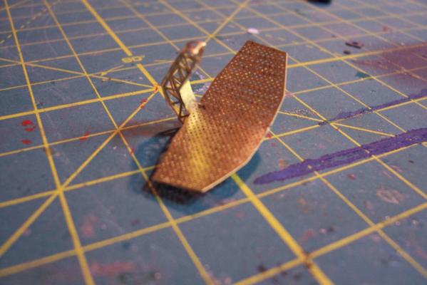
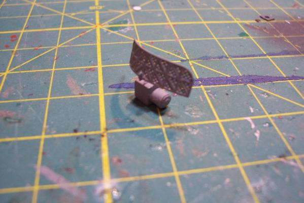
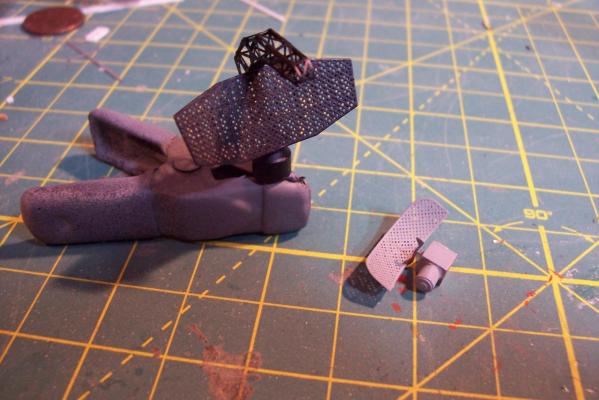
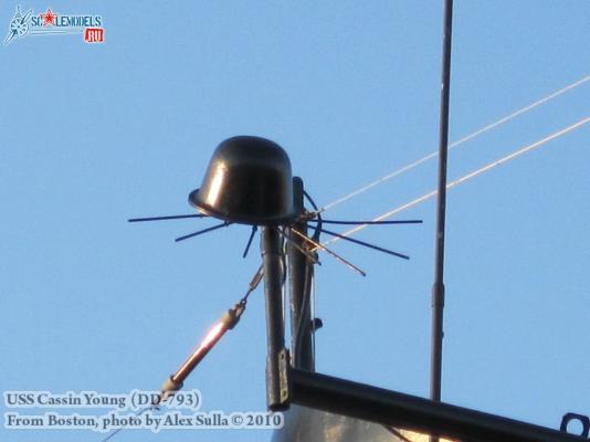
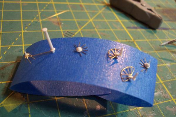
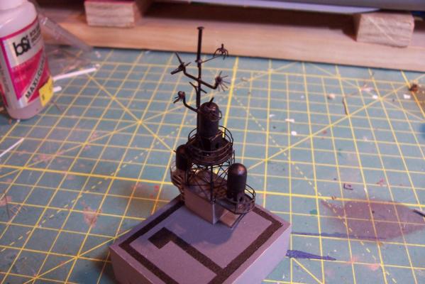
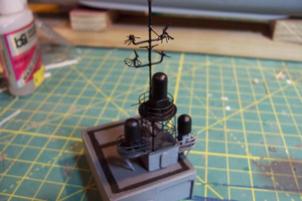
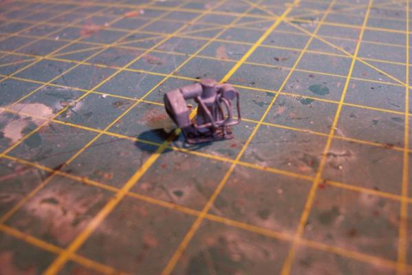
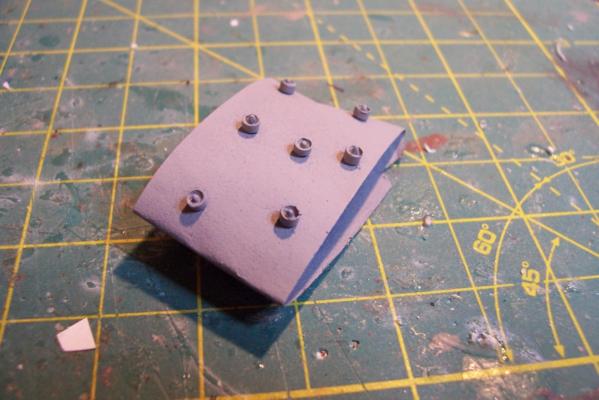
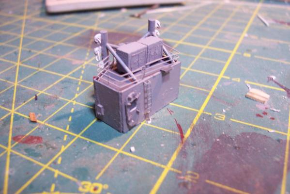
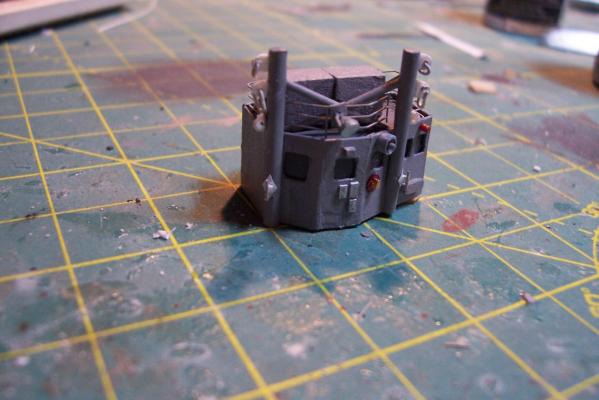
Electronic Countermeasures Tower By the early 1960’s the threat of anti-ship missiles was becoming critical. The FRAMS were equipped with a basic ECM suite capable of either jamming or decoying most of the early (and crude) missiles of the day. The kit provides a mix of wood, metal and PE parts that is an accurate reproduction of the early FRAM ECM suites. Here’s the parts: And here’s what they look like assembled (Stub mast is scratched and the kit- provided railings have not been added yet): As the Vietnam War heated up the ships deploying to the theater were at risk of the rapidly improving Soviet missiles so the ECM suites grew in size and complexity to try to keep up with the threat. Here is what most FRAMs were carrying by the late 1960’s: Since I did not have adequate plans to scratch build that larger array, and mainly because I don’t like the top-heavy look of it I decided to stick with the kit version which was on the Basilone during her 1966 world cruise. The only scratch additions were to the stub mast itself, I replaced the 2 pieces of PE that were to be glued back to back with soldered brass rod, and then I wanted to include these UFO-looking antennas that sat on the stub mast: Here is what I came up with: And here is the finished ECM tower mounted on the top of the DASH hanger:


- 144 replies
-
- 6
-
-
- basilone
- BlueJacket Shipcrafters
- (and 2 more)
-
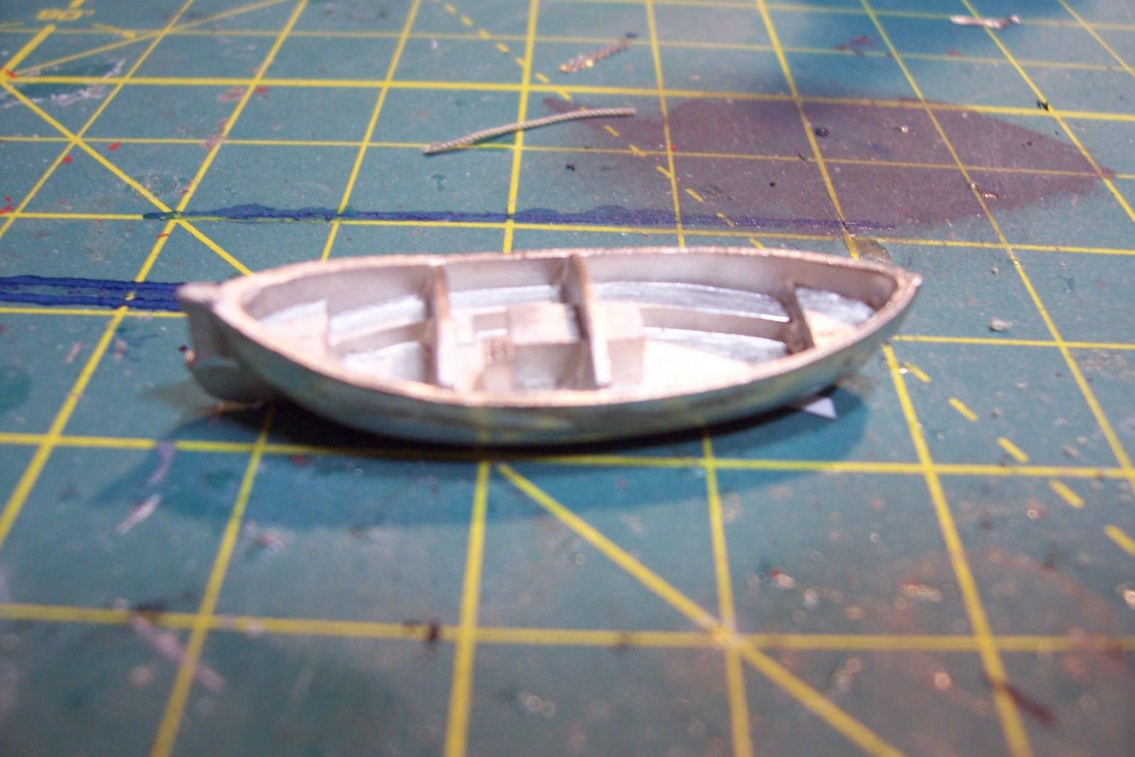
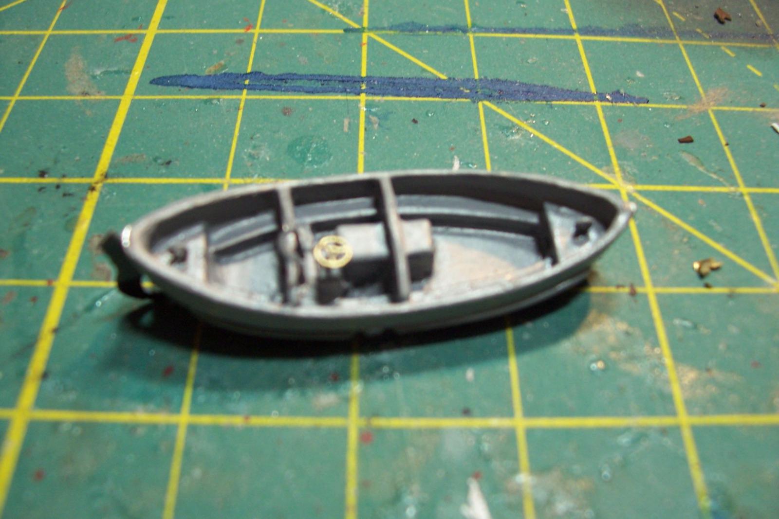
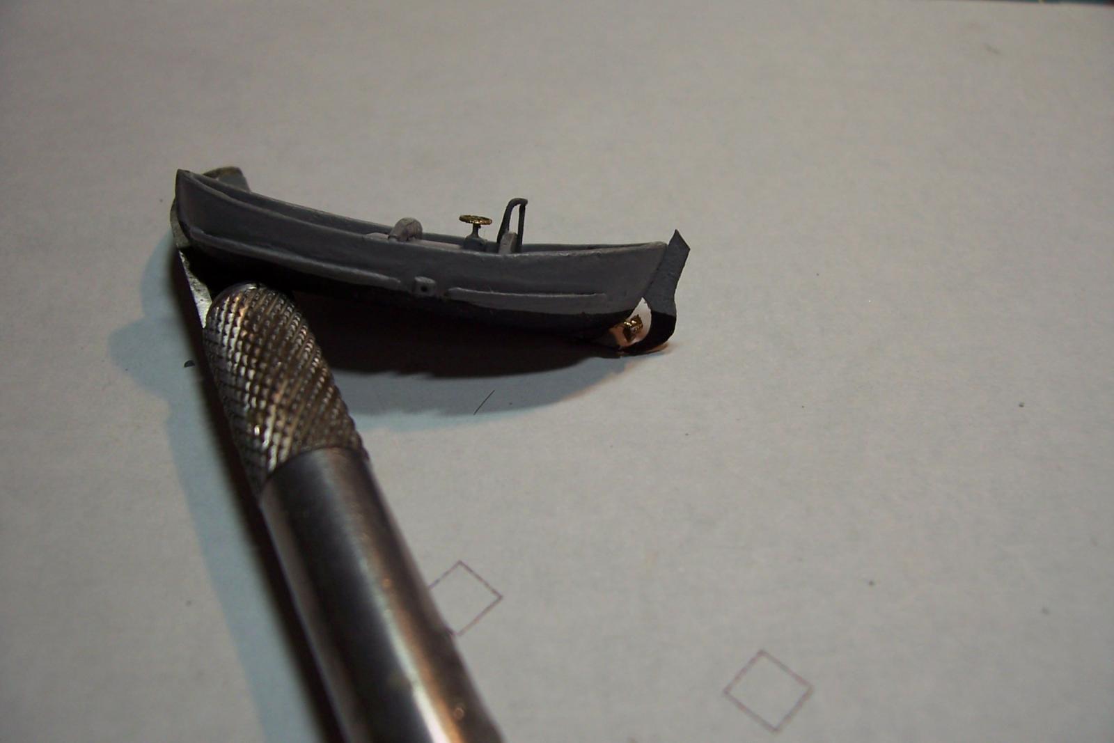
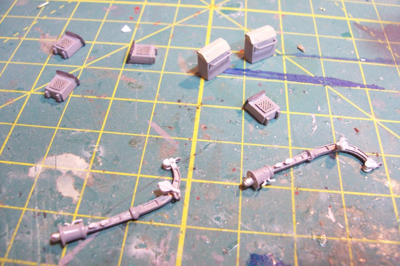
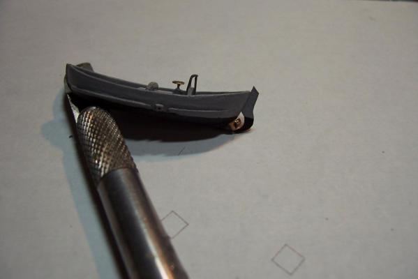
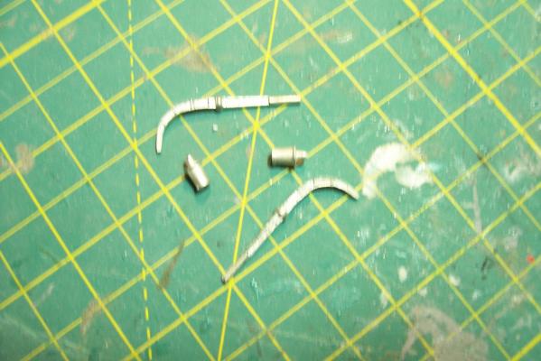
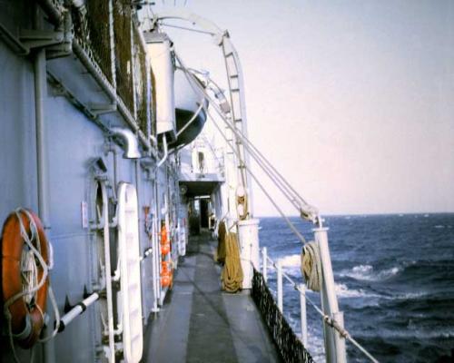
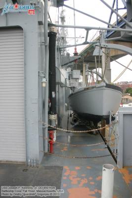
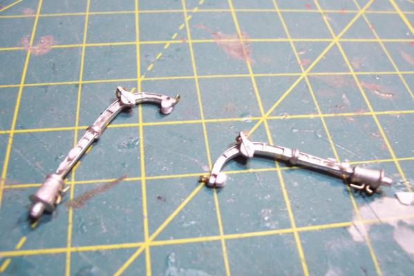
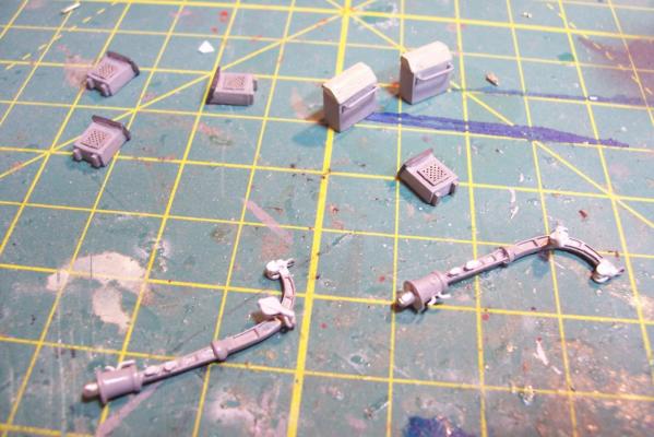
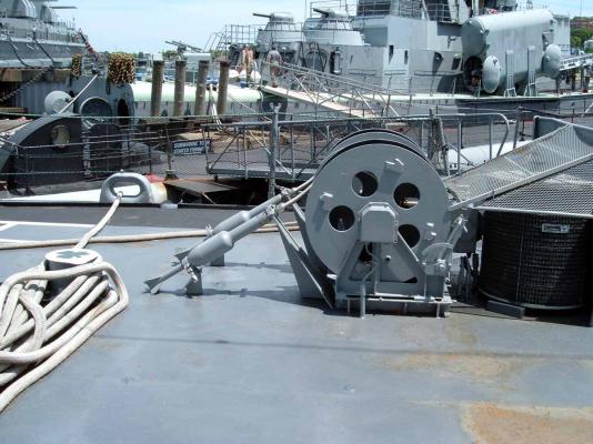
Motor Whaleboat & Davits MWB The kit provides an excellent casting of the MWB. Most of the cleanup is on the exterior, which is good since it is a lot harder to file off excess material in the compartmented interior. The only drawback to the casting is that the rudder has no space for the prop & shaft so if you decide to add them you will have to make some modifications. Here’s the casting: I cut off the rudder, drilled a hole in the hull for the prop shaft and fabricated a prop out of plastic “blades” glued to the shaft. It looks pretty awful under a magnifying glass but to normal eyesight it looks pretty realistic (it’s only about 1/16” in diameter). I then cut a new rudder with a space for the prop and glued it back on. Other details added are the rub rails on the side, the overboard discharges, back brace for the coxswain, and the steering wheel (the kit PE has an extra anchor windlass wildcat that works great for this) Here’s the finished MWB: The davits are 2 pcs of casting. I thought this would be a 5 minute job but when researching some photos online I found some stuff that should be added. Here’s the casting: Here’s some shots of the real things: The kit instructions call for using some wire for the boat falls but I wanted to rig the blocks if I could. First thing I noticed was that the upper blocks are unusual in that they are semicircular and are fixed to the davits so I scratched some out of plastic rod and sheet. Eyes were added to the top of the davits where the vangs will be attached. A single block was added to the side of each davit to guide the falls from the upper block to the cleats on the base (also added from plastic and wire). Looking at this set up I was surprised at just how old fashioned it was, I didn’t think the Navy still used radial arm davits, rope boat falls and snubbing cleats in the 1960’s. Sure it was reliable but it was also a pretty dangerous way to launch a boat. Raising it was also complicated with the falls having to be led to the fantail where a double headed winch was located. All in all a very manpower intensive operation where plenty could go wrong. Here’s the finished davits and also the kit provided vegetable lockers and two flag bags:


- 144 replies
-
- 6
-
-
- basilone
- BlueJacket Shipcrafters
- (and 2 more)
-
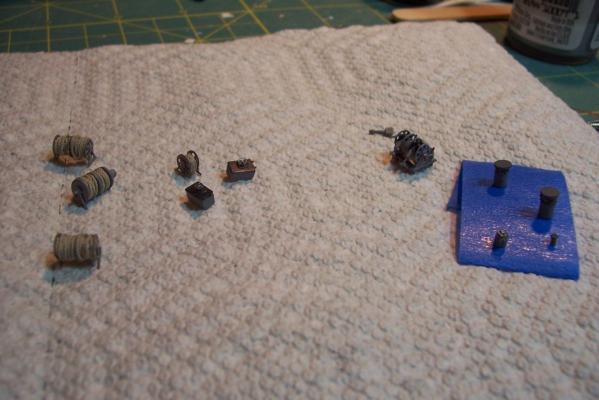
Focsle & Fantail Deck Furniture Fanfare Reel The FRAMs carried the MK6 Fanfare Torpedo Countermeasure system, consisting of a noisemaker towed behind the ship to spoof acoustic torpedoes. Here’s what it looked like: I scratched a reel out of leftover PE line reels from the kit with the foundation, gearboxes, motor, etc made from styrene. All this is some small stuff that will sit on the focsle and fantail, things like horizontal hatches, vertical vent blowers scuttle, line reels. The stuff on the left is OOB from the kit, the things on the right are scratch, and the stuff in the middle is a combination of both:
- 144 replies
-
- 4
-
-
- basilone
- BlueJacket Shipcrafters
- (and 2 more)
-
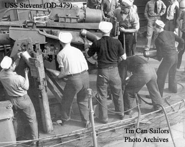
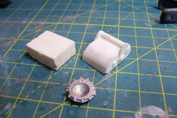
5” Practice Loader Like most ships armed with 5” guns in the early 60’s, the Basilone had a practice loading machine so that the crews could increase the manually-loaded guns’ rate of fire and not get killed or hurt in the process. The electro-mechanical based analog fire control systems of that day were not nearly as “tight” as the computer-based digital systems in use today that can come close to delivering “one shot - one hit,” even on high-speed maneuvering targets. In order to increase the probability of getting a kill on an air target the number of rounds had to be increased by increasing the rate of fire. An equally important goal was to reduce the risk of loading crews getting hurt. The inside of a 5 inch gun mount is very constricted, every surface is slick with oil, grease or hydraulic fluid. The mounts slewed rapidly when tracking a target making it difficult to maintain balance and footing and anyone who failed to remain clear of the recoiling gun would have been mashed; hence the use of practice loaders that allowed the crews to choreograph their movements without the risk of getting hurt. Here’s a shot of a WWII gun crew practicing on a loader: The kit provides a brittania casting that is really quite good given its size. Since I wanted to include the open base and the loading platform I decided to scratch my own. The two castings on the left where ordered from HR Products, the better one on the right is the kit-provided one. Here’s the finished scratch version with the kit casting as a comparison:


- 144 replies
-
- 5
-
-
- basilone
- BlueJacket Shipcrafters
- (and 2 more)
-
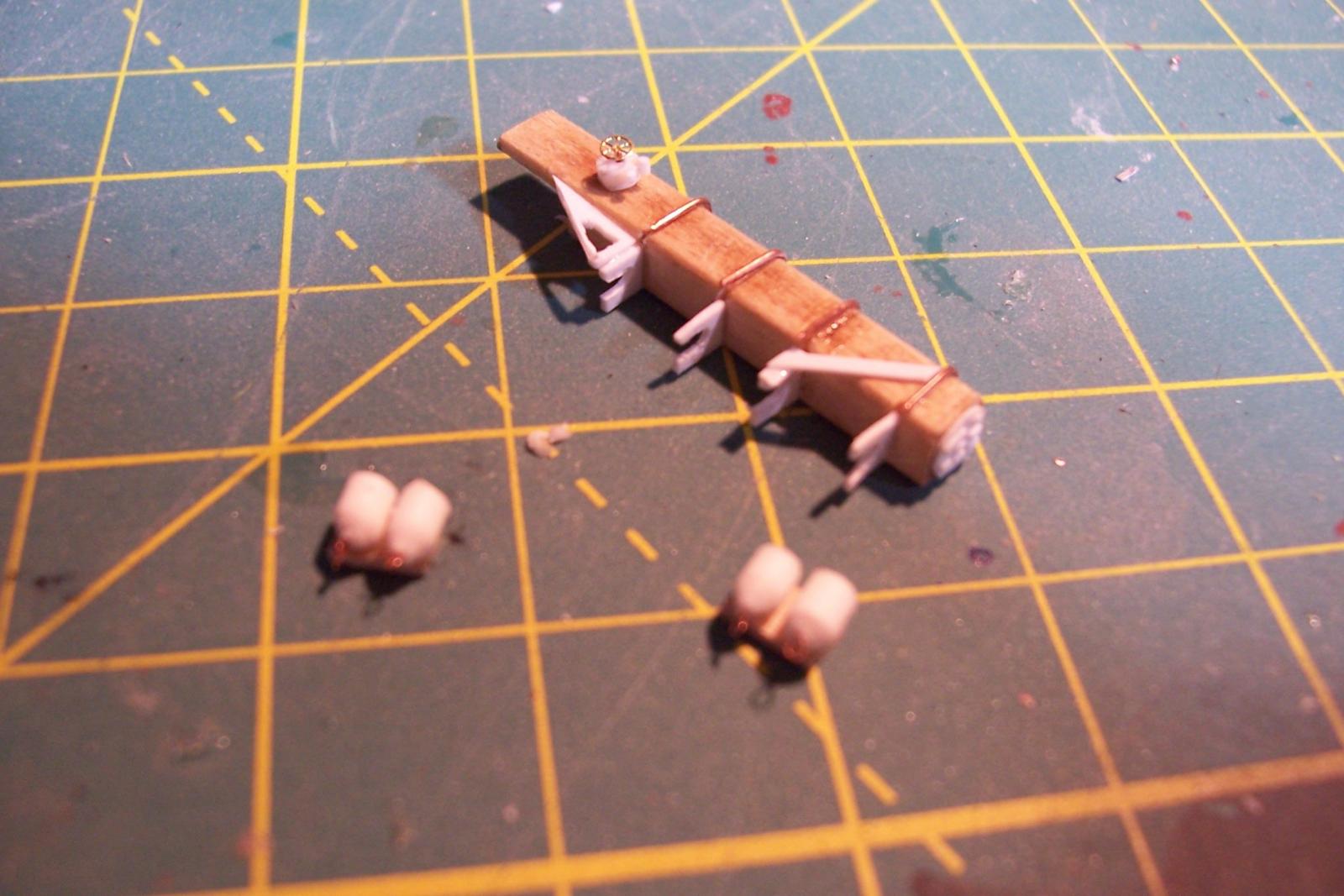
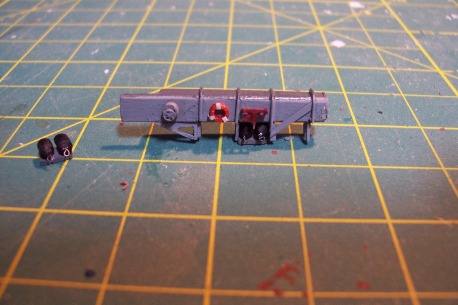
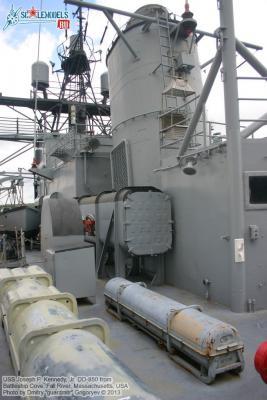
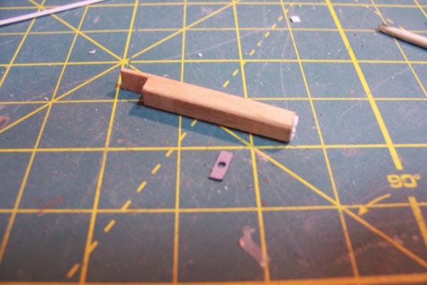
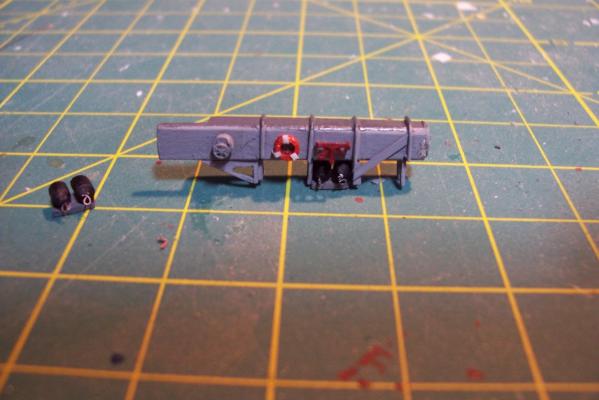
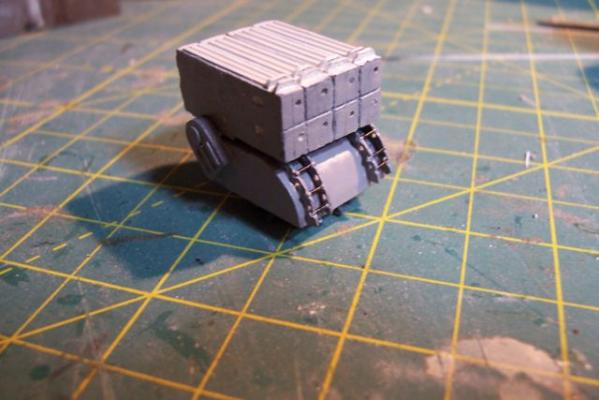
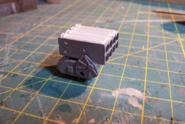
ASROC RAMMER RAIL STOWAGE The final big piece for the ASROC deck is the long stowage locker for the ram rail for the ASROC Loader. Here’s what it looked like: The kit provides a rectangular piece of laser cut wood and a small piece to support it off the deck. In this pix I’ve already rounded the edges and added a door to the front with some plastic bits to give the impression of a waffle pattern ( there was no way I could fit 16 at this scale so I’m just going for the impression): Here’s what it looks like after the addition of the access scuttle, hose rack, support legs, braces, and stiffeners. The blueprints indicate that the area under the locker was used to stow “portable” fenders. The Navy has always had a pretty loose definition of “portable,” if it took 6 men and a boy to move something it was still considered portable. I scratched some fenders to place under it. I needed a life ring for here and other places on the build but I could not find any after marked items. I called Bluejacket to see if they had any (they didn’t) but Dr Al Ross, the kit’s designer had a good idea - use 1/8” hollow plastic tubing, which I did. The inner diameter was increased with a rat tail file and the outside edge filed to a rounded edge, it was cut to length (short!) and the edge rounding repeated on the new face. Some paper strips serve as the mounting brackets. Here’s the locker and fenders after painting. Finally here are the major pieces of the ASROC deck dry fitted to show their relationship (lockers and vents will be added later):

- 144 replies
-
- 6
-
-
- basilone
- BlueJacket Shipcrafters
- (and 2 more)
-
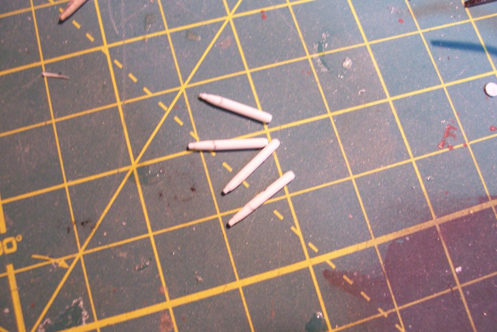
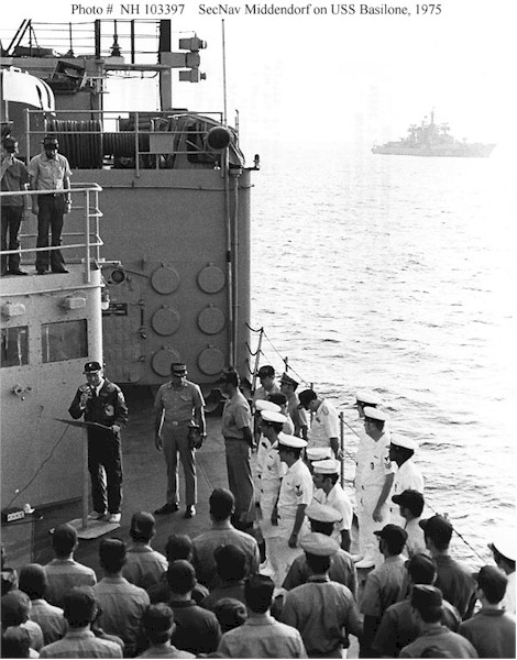
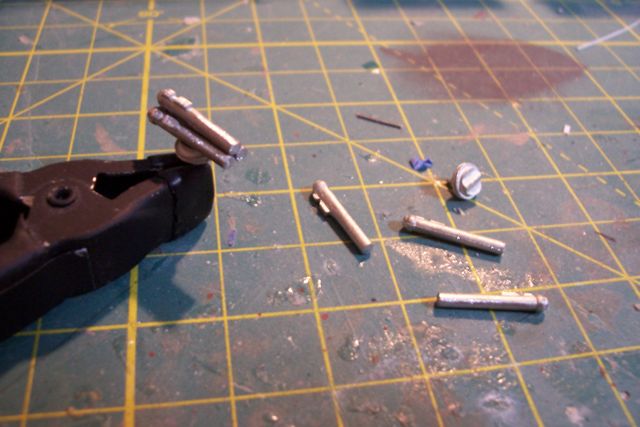
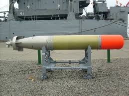
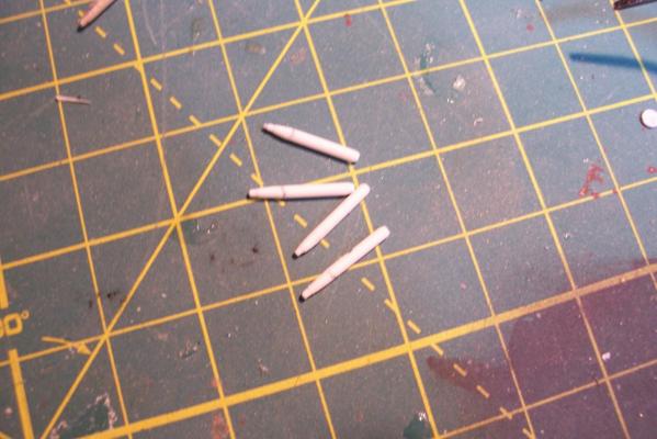
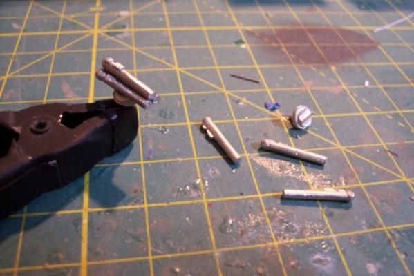
Torpedoes The FRAMs carried MK 44 Acoustic torpedoes, they were carried by the DASH drone, used on the ASROC missiles and in the over-the-side MK 32 Torpedo Tubes. Here’s what they looked like: I wanted to include one on the DASH to help show what it was for and I noticed from the blueprints that there was a “dummy torpedo stowage” rack on the ASROC deck. A little photo research turned up this pix showing the Secretary of the Navy addressing Basilone’s crew. This pix brought back some memories, first of all its easy to assume it was taken in the MED since there is a Soviet cruiser anchored in distance. Since the Soviets couldn’t get access to most ports during the cold war they spent weeks anchored near Cyprus at a “shallow” spot known as Kithra anchorage, it was for all intent open ocean and the anchorage was on a seamount that could barely be reached using all the anchor chain onboard. Since they were there that’s where the USN was too. You can bet that SECNAV thinks the crew is thrilled that he is there and you can assume the crew cares only about the fact that this guy is eating up their off-watch time. On the right side of the photo the torpedo chocks can be see so I’ll make mine to match. Fortunately the MK44’s had a 12 inch diameter which at 1/192 scale comes out to 1/16”, a standard size for plastic rod. After cutting the rod to length it was easy to chuck them up in a Dremel and give the warhead end a bevel and narrow down the aft end so they look like this: A little strip plastic to simulate the steering vanes and their shroud, and then painting the DASH one to look like a warshot and the dummy torps blue they look like this:

- 144 replies
-
- 6
-
-
- basilone
- BlueJacket Shipcrafters
- (and 2 more)
-
I was struck by the sharpness of your white trim around the hull, particularly since you had to zig and zag around a lot of projections. Any tricks to how you did it or was it just a matter of taping it off with lots of trimming and adjusting?
- 2,250 replies
-
- 1
-
-
- model shipways
- Charles W Morgan
- (and 1 more)
-
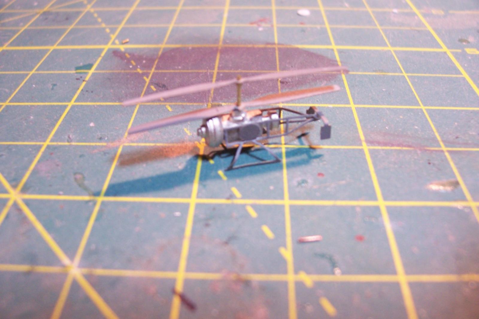
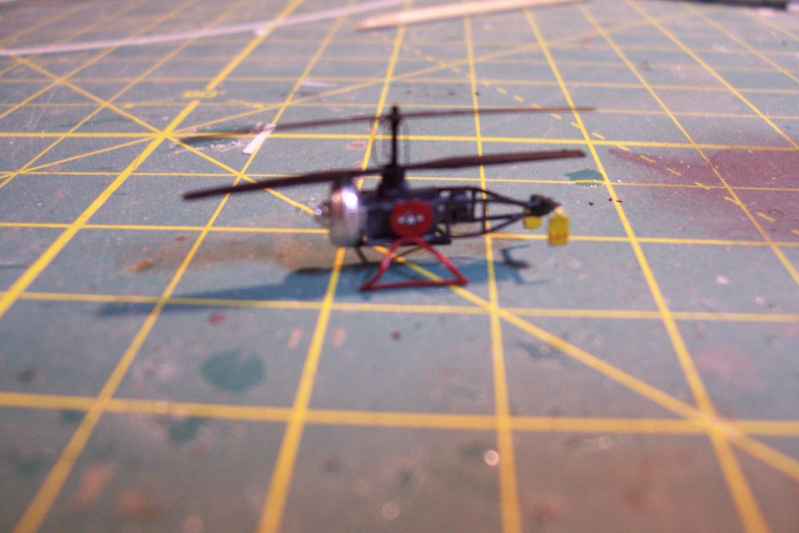
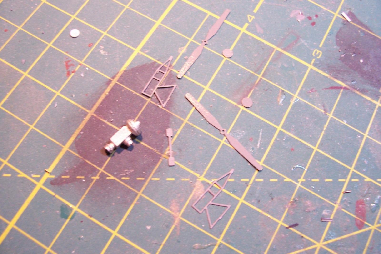
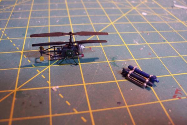
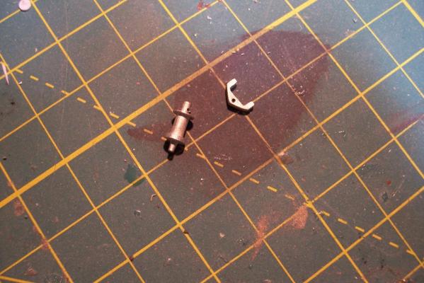
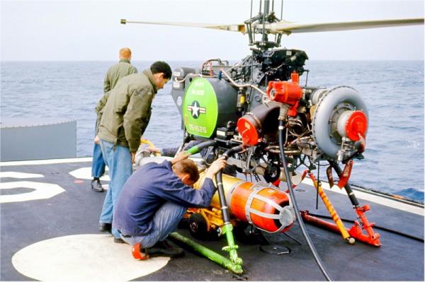
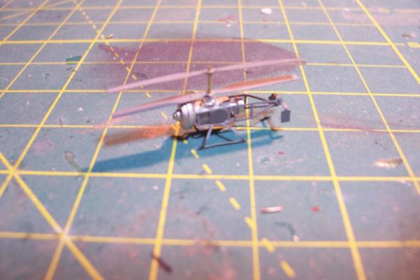
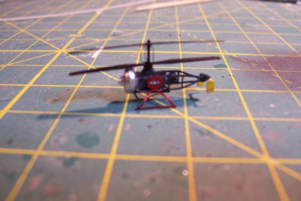
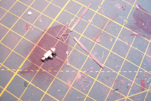
ASROC Loader The loader was used to pick up ASROC missiles from a dolly or container and ram them into the box launcher. The kit provides several britannia metal pieces and 2 brass PE pieces (not shown). I won’t be using the PE on my build because the long loading arm was usually stowed away except when actually loading. Here’s the brittania parts: Here’s what the loading arm with a missile looked like: The loader had a real rat’s nest of hydraulic lines that I would like to include an impression of so I’ll scratch build the loader out of plastic, brass wire and paper. Here’s what I ended up with: DASH Drone The DASH was used to deliver torpedoes or nuclear depth charges at ranges beyond what the ASROC could reach (always a good idea when dropping a nuclear weapon) The kit provides a brittania body and several pieces of PE, the only details I’ll add will be some of the push rods below the rotor blades. Here’s what it looks like assembled And here it is painted (red and green sides so the operators could figure out what side they were looking at) . Fortunately I had some 1/700 decals which worked great for the dash insignia and warning stripes at this size.

- 144 replies
-
- 9
-
-
- basilone
- BlueJacket Shipcrafters
- (and 2 more)
-
Thanks Brian. I'm impressed with your Bismarck, I've heard of the kit but I was not aware it had so much PE, you'll earn a PhD in PE by the time you finish it. Tim
-
Wow. I've been putting off making these for my Willie B because my soldering skills are a little shaky but if you could keep the old solders from melting when making the new ones using alligator clips and damp towels maybe I can too. Great job on the dredges!
-
Hi Rick, I'm moving a little slowly on the Basilone because Trout stocking season has just started here in Virginia and the weather is perfect, and of course postseason baseball has just started with the Nationals actually in the middle of it. Hopefully I'll be making another small post in a day or two. Keep plugging away on the Willie B. - I learned more from that build than all the others I have done. Tim
-
Rick, Glad to have a real destroyerman following along on this build! Your work on the Willie B will put you in good stead for taking on the FRAM kit. Just like the Willie B's instructions the ones for the Gearing kit tell you what to do but not always how to do it. You will also find that the Gearing requires less scratch building than the skipjack does so, with the exception of carving the solid hull, you should not see anything that you haven't done before -plus you won't have to sew any sails! Tim
-
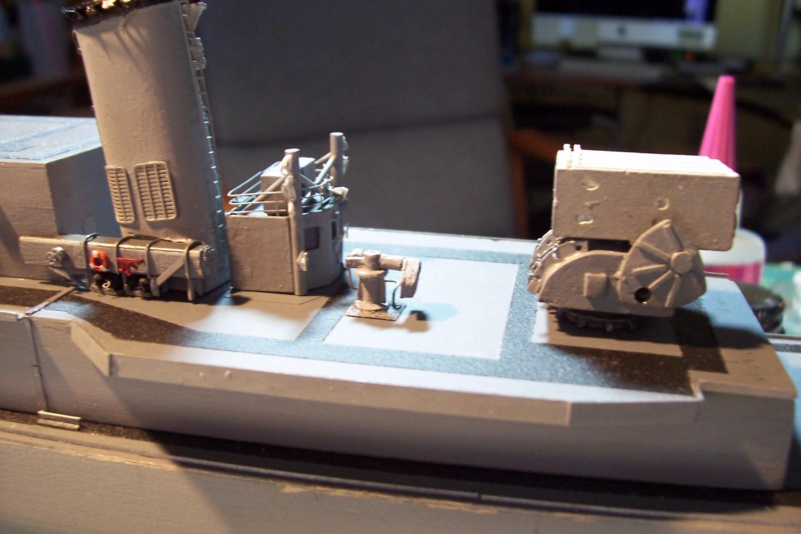
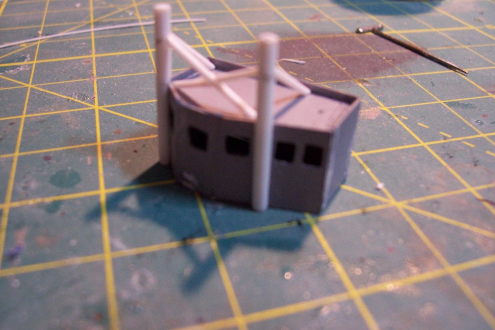
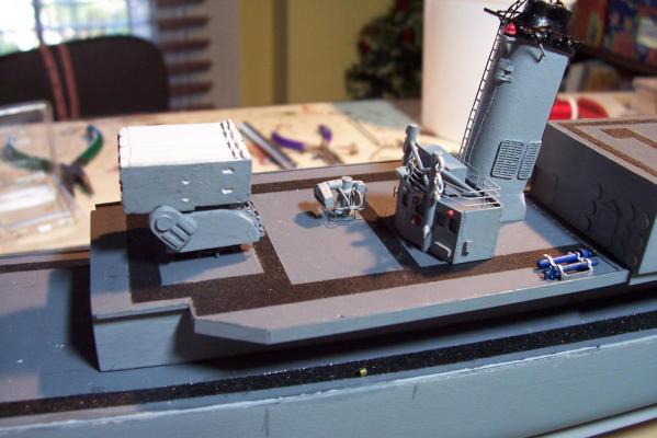
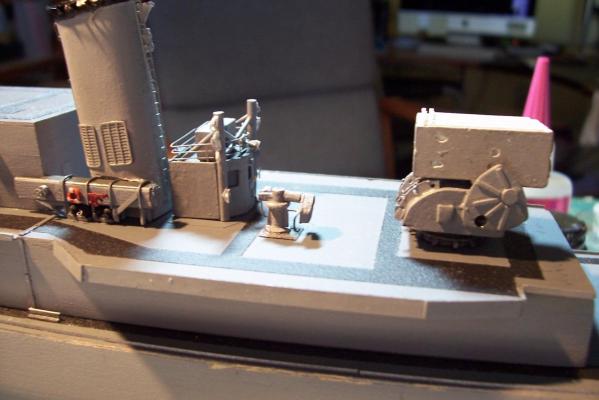
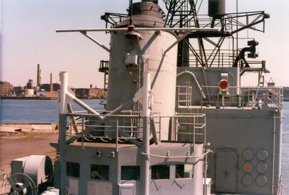
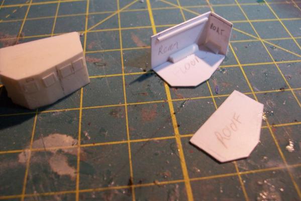
ASROC Control Station The FRAMS had control station for the ASROC Launcher that also served as a security control point since the system was nuclear capable The kit provides a resin casting for the control station that is perfectly servicable. Unfortunately for my use, the windows on it are a style that the Basilone did not have so I will scratch build the station. Using sheet plastic and the kit’s casting as a guide it was pretty easy to fabricate a new one. The kit also provides 2 pieces of Brittania metal to serve as the Replenishment at Sea (RAS) king posts which are located on the front of the station. I decided to build my own out of plastic because I find it easier to work with and I wanted to add an extra support leg to each kingpost. Here’s the station with the kingposts: After that it was just a matter of adding some scratch details. I needed a loudspeaker for the front of the station so I made enough for the rest of the build while I was at it. The details include: lifejacket lockers on top Launcher train warning bell Launch warning siren windshield wiper motor Floodlight Padeyes, longlinks and cleats on the RAS posts (the white stuff) several photo etched aluminum safety placards (never read) Sound powered phone storage box junction box WT door


- 144 replies
-
- 6
-
-
- basilone
- BlueJacket Shipcrafters
- (and 2 more)
-
Thanks Ken, that's all I needed to know! Tim
-
Carl, Looks like you picked a beauty, should turn out to be a great model. Could I ask you to pull a quick measurement off the plans? I'd like to know the max length of the model, from the tip of the bowsprit to the aft most end of the boom on the main mast. I'm asking because the Model Shipways catalog shows the length as 36.5" but I happen to have a copy of the box cover (sent as packing material when I ordered another MS kit) and it shows the model's length as 43". Could you tell me which is correct? thanks Tim
-
ASROC Launcher The kit provides 2 resin pieces and a Brittania base. Given the large size of this item I thought it would lend itself to some scratch additions, unfortunately I got a little carried away and added about 50 pieces which is a bit much at this scale Here is what the parts look like after the addition of the scratch items to include: circular and rectangular inspection and access plates on the sides of the base curved ladders on the front of the base perforated I-beam stiffners on the top of the box cooling water channels on the top of the box drilled out the access ports on the doors where firefighting applicators could be inserted in case of a motor ignition And here’s the completed assy after painting:

- 144 replies
-
- 6
-
-
- basilone
- BlueJacket Shipcrafters
- (and 2 more)
-
Bill, great looking build! Couple of questions: - Where did you get your plans? - What types of things are you using HR products for (I know there isn't much available from anyone in 1/16 scale)? How would you rate their quality? - I've been looking at this BJ kit for sometime as a possible future build - did you find thinning the bulwarks difficult? Looking forward to following this one! Tim
-
Foxy, I've had this kit in its box sitting behind some furniture in my living room for 10+ years, unaware the PE kit was out there. Now I'm thinking it may be time to break it out and follow along behind you. Great work so far. Tim
-
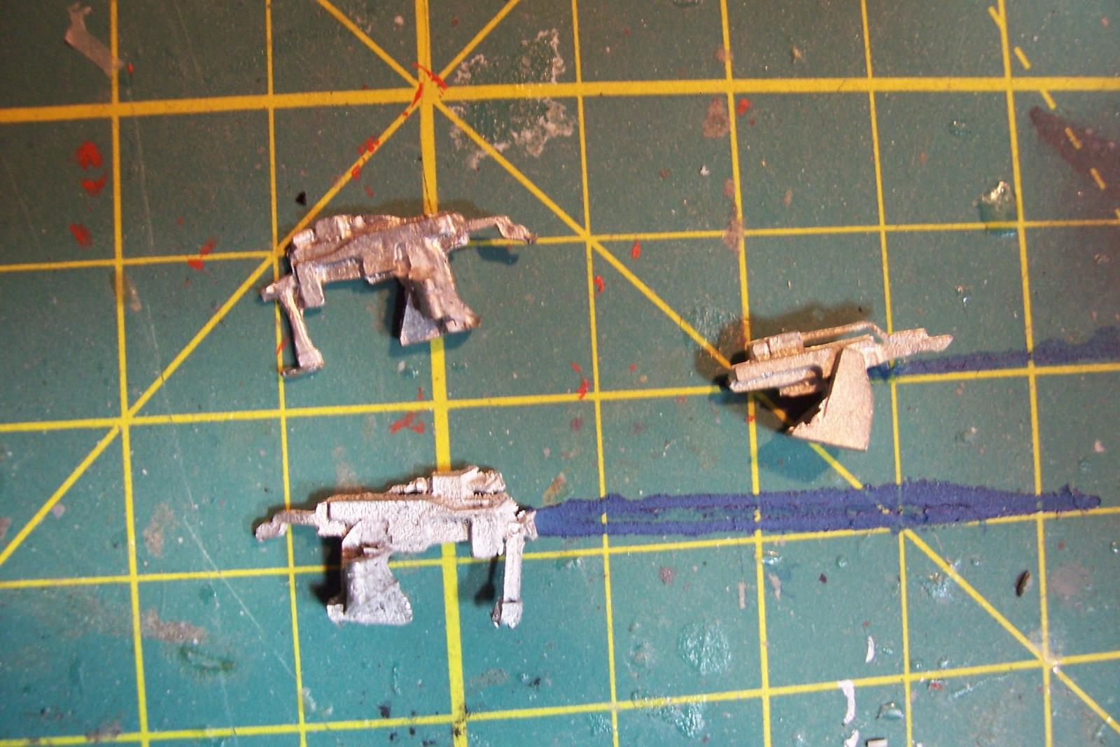
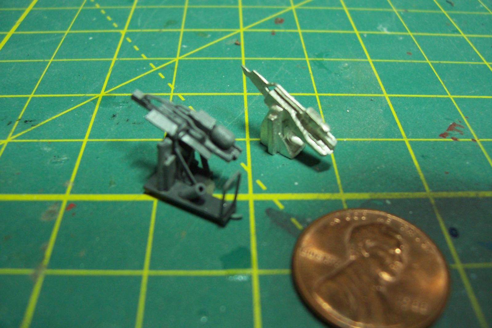
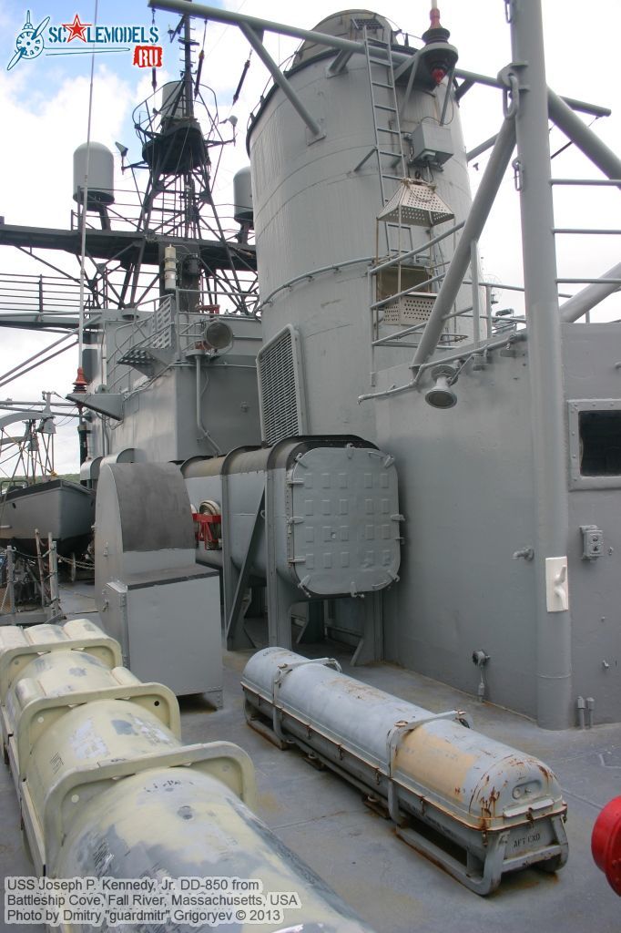
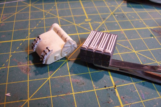
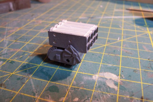
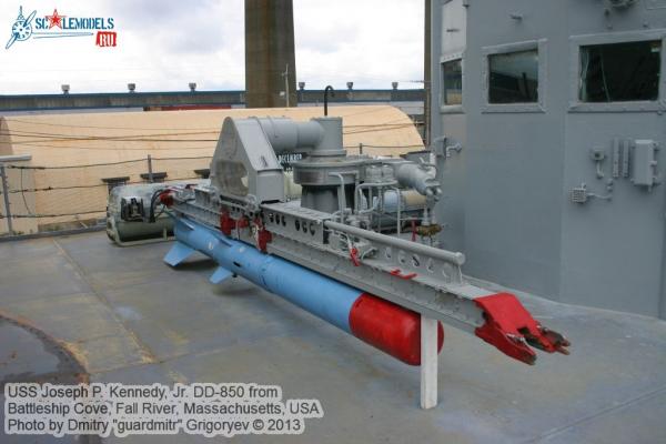
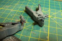
MK32 Torpedo Tubes Summer activities have slowed work on the model but I'm getting some small stuff done. The 2 torpedo mounts were easy. They consist of 3 tubes and a base, all cast brittania. The bottom 2 tubes rest on the base and the top tube rests on the two lower ones but since the breach ends are larger than the muzzle ends some spacers were added to keep the axis' of all three tubes parallel. The photo above shows what the mount looks like without the spacers. Scratch additions include various junction boxes, fine wire to simulate knobs, a long storage tube on the upper tube, and the fiberglass muzzle covers


- 144 replies
-
- 5
-
-
- basilone
- BlueJacket Shipcrafters
- (and 2 more)
-
Thanks for reposting your pix, this was always my favorite build log. Your woodworking, painting and chain-forging skills are unequaled. Can't wait to see the rest! Tim
-
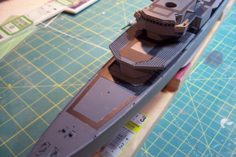
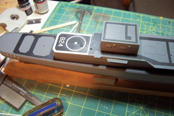
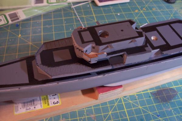
More Non-skid Finished the non-skid tracks on the rest of the decks and the final waterways and scuppers. All the superstructure pieces are just dry fitted at this point. Flight deck markings are a combination of: - Spray paint (landing circle) - Dry transfer decals (numbers) - Pin striping tape (deck edges) Finished up with a coat of dull-coat. The lines in the center of the flight deck are etchings in the laser cut deck to represent the plates covering a collapsible replenishment kingpost. Only scratch adds are 2 escape scuttles. Next item will be adding striping to the deck edges to cover up the I-beam ends and add deck coamings.

- 144 replies
-
- 9
-
-
- basilone
- BlueJacket Shipcrafters
- (and 2 more)