schooner
-
Posts
741 -
Joined
-
Last visited
Content Type
Profiles
Forums
Gallery
Events
Everything posted by schooner
-
 Thanks Patrick. Although I enjoy doing this kind of stuff I've figured out that 1/192 is the smallest scale I can handle - I have no idea how the folks working with 1/350 scale, let alone 1/700, do it.
 -
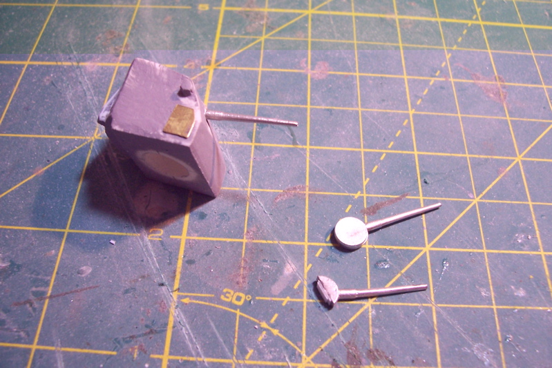
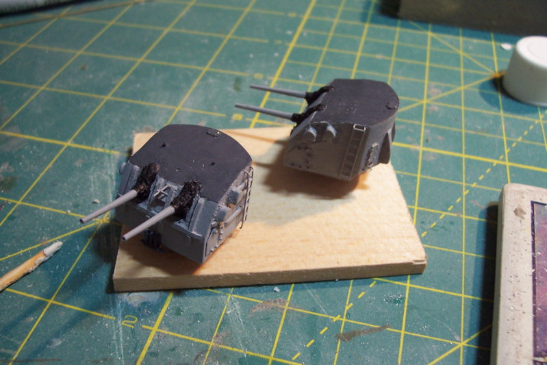
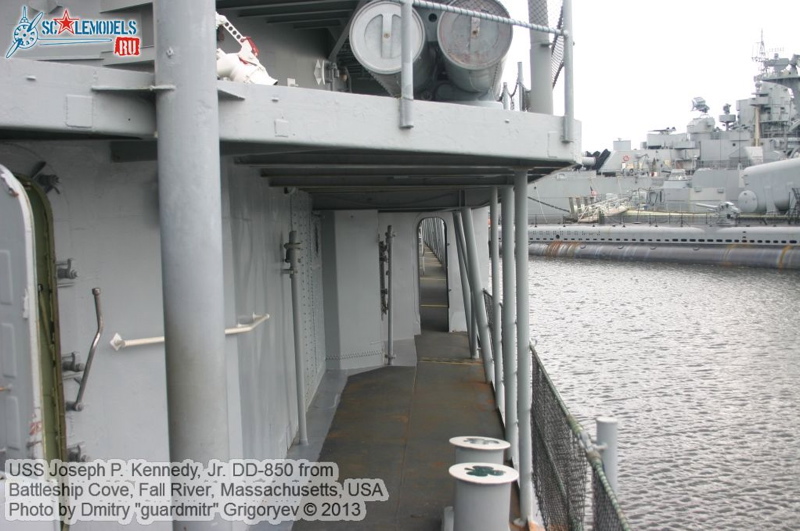
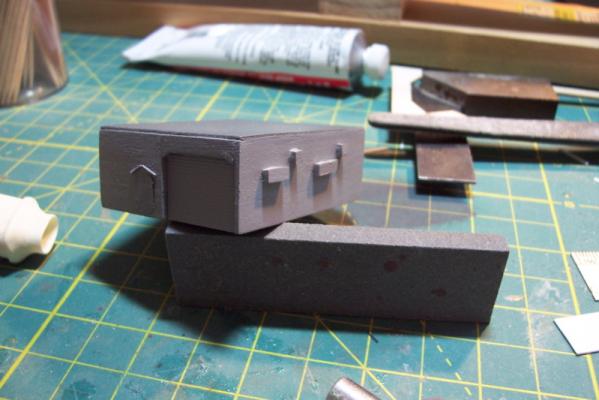
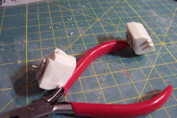
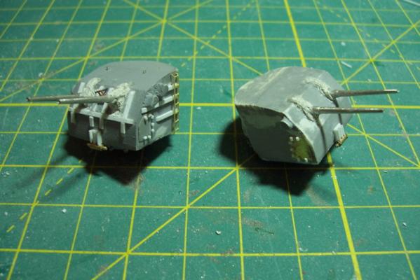
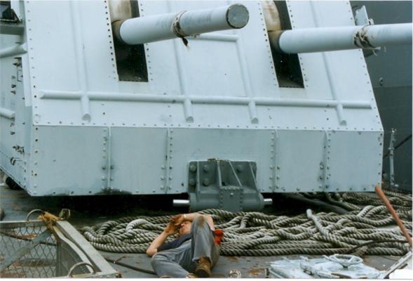
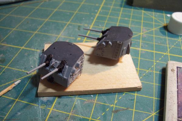
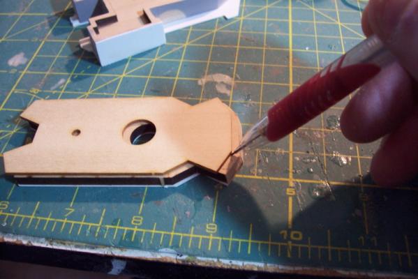
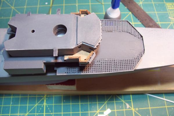
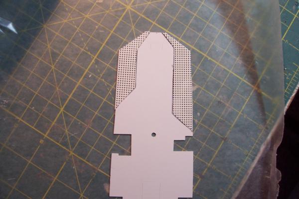
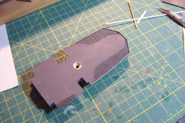
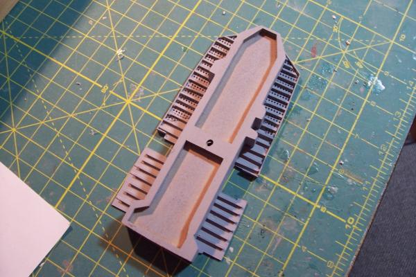
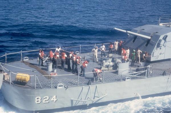
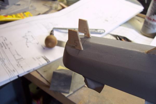
DASH Hanger Very simple assembly. The usual 3 lifts of wood topped by a sheet plastic deck. The only anomaly was during my trip up to the USS Joseph P. Kennedy Jr in Fall River Mass I noticed that she had 9 blow-out hatches on the forward face of the hanger/ASROC magazine, not 6 as per the kit instructions. After I got home I did some research and found out that the Basilone had 9 too. Problem was that there was not enough room to fit the extra 3 hatches because the kit assembly has the starboard half the hanger extending about 1/16” forward of the port on the forward face. Checking the plans the forward face should be flush so I removed all the PE and sanded the forward face flush and made up 3 extra hatches out of plastic to match the 6 PE hatches. The large WT doors on the fore and aft faces are from the 1/192 USN Door set from Tom’s Modelworks. Fortunately the fret had a few large doors which correspond to the doors on these ships at that location, needed to move the ASROC missiles in and out of the magazine. 5/38 Gun Mounts The mounts are cast from resin with Brittania metal barrels and mounting rings. I removed the gun captain hoods from the top of the mount because Basilone didn’t have them. The bottom of the castings are drilled out to accommodate the mounting rings with a length of 1/16” brass rod to pin them together. The rings have a shallow collar that the mount rests on but to my eye that made the bottom of the mount sit too high of the deck so I removed the collar, I also extended the brass rod so that I could use it to pin the mount to the main deck. The barrels have a circular base that is trimmed at whatever angle you want the barrels to be at – I made the aft mount level and the forward mount elevated to match the rise of the focsle. I drilled out the ends of the barrels using the smallest bit I had (size 71) and then enlarged the holes with a rat tail file. The kit provides PE vertical ladders, I added the reinforcing bars on the forward mount (meant to protect it from breaking seas), access panels on the sides, the canvas gun bags (bloomers) around the base of the barrels,the mechanical train stops on the bottom of the front of the mount, aftermarket PE doors, hatches and grabrails. Next up will be the Gun Director assembly


- 144 replies
-
- 6
-

-
- basilone
- BlueJacket Shipcrafters
- (and 2 more)
-
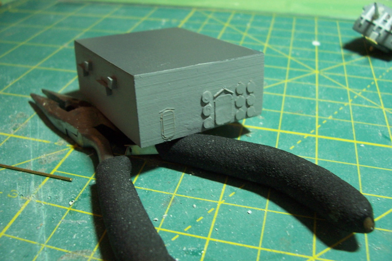
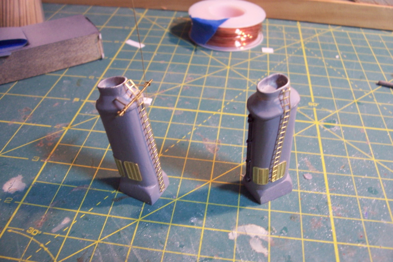
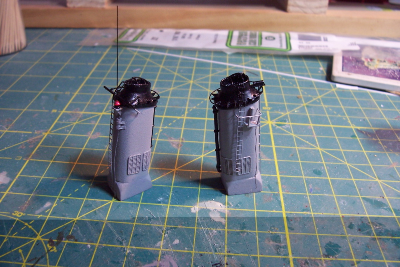
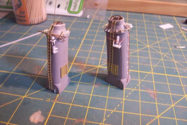
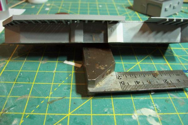
Stacks Although the instruction book calls for these to be put together further down the road I decided to do them and the other deck details now before I paint the hull so that the time I have between painting the hull and finishing the build is minimized to reduce the chances of damaging the hull’s paint job. The stacks are cast from resin. After washing them with warm soapy water to remove the mold releasing agent they only needed a little putty to fill in a couple of small pits. Here’s what they look like after the kit-provided details have been added: Here’s what they look like after my scratch additions to include: · Stack cover support grids · Grabrails · Antenna couplers (tuners) with RF cables · Ship’s whistle with steam pipe · Work platform · Insulators on whip antenna And finally, with their final paint job: Next up will probably be the DASH hanger.


- 144 replies
-
- 8
-
-
- basilone
- BlueJacket Shipcrafters
- (and 2 more)
-
Hi Patrick, Should you decide to model one of Connie's battle stations you might consider asking some help from the US Navy Museum at the Washington Navy Yard, they have a full scale mockup of 2 of Connie's guns on the gun deck. A little phone time and I'm sure you could find someone who would agree to take some photos if you mailed them a drug store camera and a return envelope. If no luck let me know and I could run down there and take some pix for you. Of course the folks onboard the real USS C up in Boston would probably do the same thing too. Tim
-
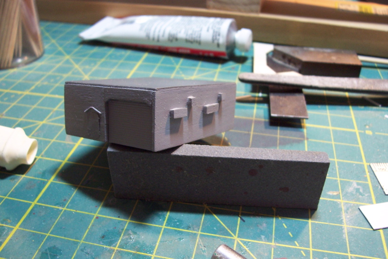
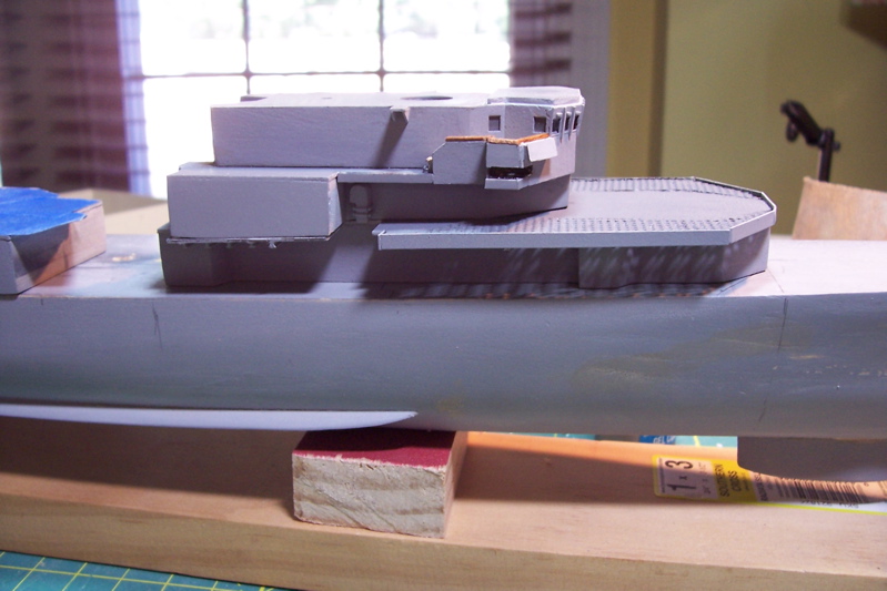
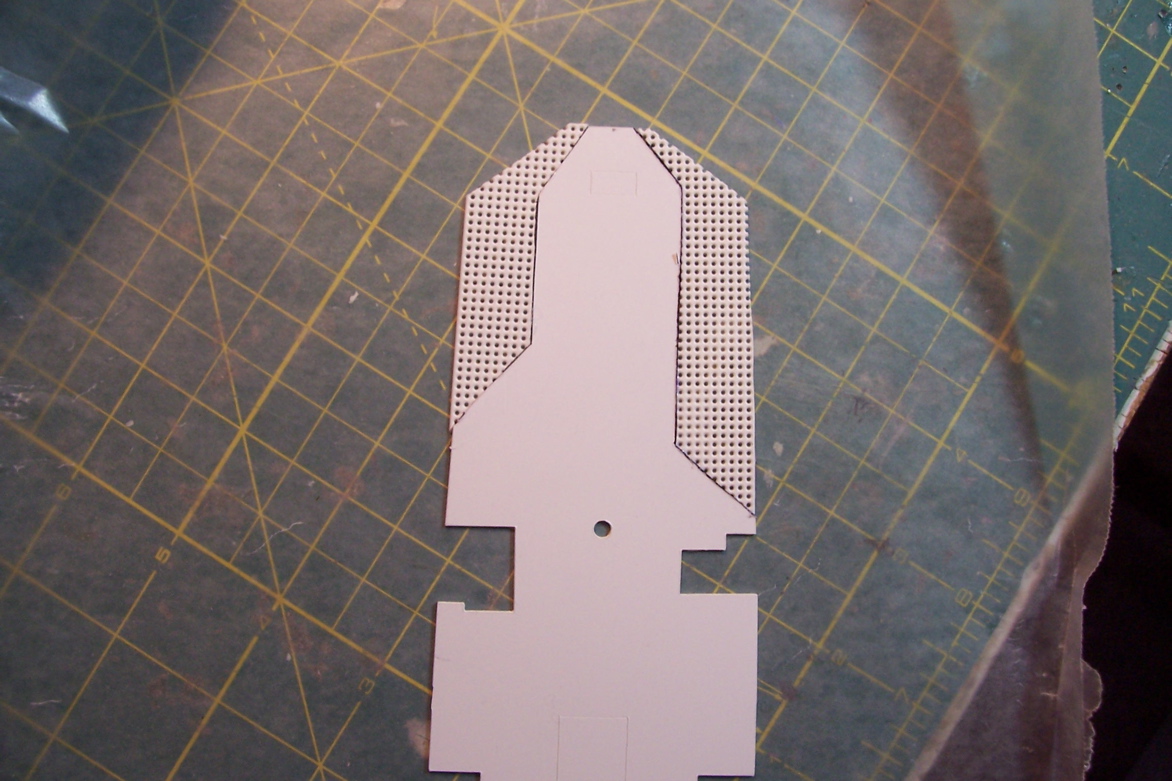
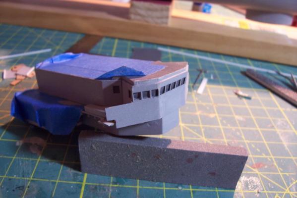
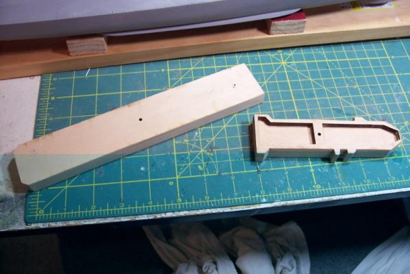
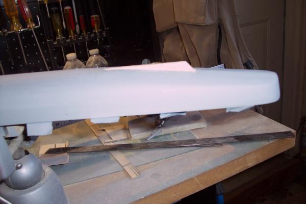
Thanks Patrick! The Pilothouse This took me a lot longer than I thought it would. Lots of little, fragile parts make for slow going and frequent repairs I guess. The pilothouse, like the rest of the superstructure assemblies is made up of wooden lifts topped with a sheet plastic deck. The order of putting them together is a little different in that the top 2 are glued together then the 3rd piece is laid on them and a line traced to determine how much of an angle must be sanded into the front 3 faces so that they have a subtle “tilt” forward. Here’s the line being drawn (exaggerated for illustration): And here is the all four lifts glued together with the tilt in place. I had originally intended to depart from the instructions in order to fabricate an open pilothouse where I could put plexi in the windows and have the bridge doors open but after actually handling the parts I realized it was beyond my abilities. The front and sides of the pilothouse are made up of 7 pieces of 1/64” plywood, 3 of which have to bend to create the tilt. If I had tried to use just those, assuming I could put them together without looking awful, they would have been VERY fragile and I’m sure I would have crushed the front of the pilothouse at some point in the build – so I decided to follow the instructions. Painting is not one of my strong points so to avoid trying to get good demarcations between the dark “interior” of the windows and the haze gray exterior I just painted the background pieces where the widows would be dark gray and then glazed them. Once the thin ply pieces were on it looked OK. Adding the bridge wings was slow work. The stiffeners between the windows was quick. The small windshield wiper motor housings above each window are my addition. Here’s what the completed pilothouse looks like resting on the bridge assembly, the scratch additions are the wood cap rails on the bride wings, the venturi wind deflectors on the front of the bridge wings and the 3 small deck extensions on the top deck. Details like doors, ladders, portholes, etc will be added later. The next item will be the DASH hanger which should be easy.

- 144 replies
-
- 7
-
-
- basilone
- BlueJacket Shipcrafters
- (and 2 more)
-
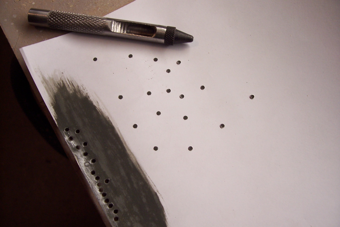
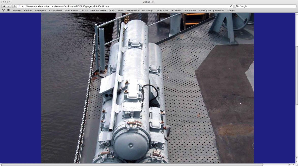
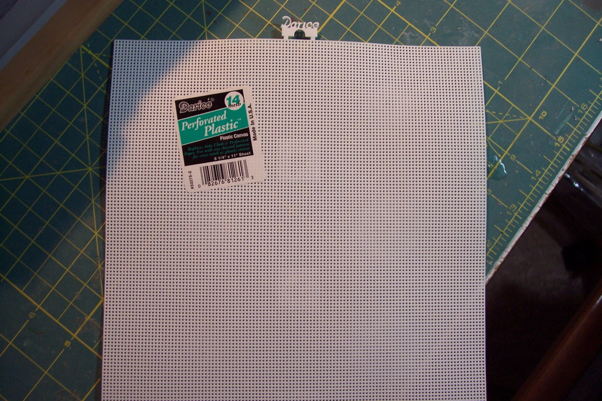
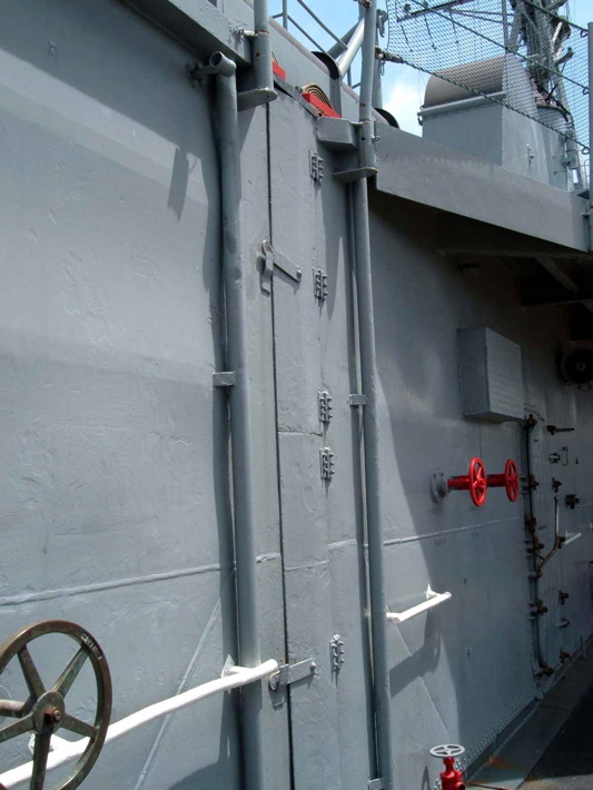
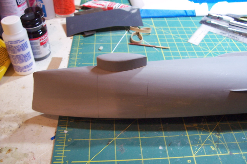
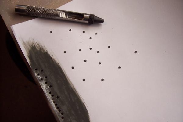
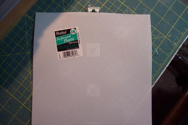
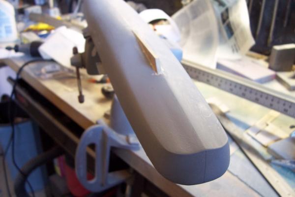
Modifying the forward 01 level deck I ended my last post about the possibility of trying a new way to make portholes. It comes from the Waterline Warships book I listed on my first post. Basically a punch is used to punch about 2mm deep into the wood, a solid rod is then pushed against the circle, depressing the circle by 1 mm or so. The punch is then used to punch out discs of painted and glazed paper. The discs can then be glued into the depressed holes giving a pretty good simulation of a porthole with out the tear-outs associated with drilling them. Bottom line: I could not make it happen, I needed a 2mm hollow punch to get the right scale. The only thing I could find online for less than $50 was a leather punch set. It worked fine for making the paper discs but the outside diameter was too big. The technique is worth remembering if you can find (or make) the right punches. I couldn’t so I’ll be going with some aftermarket PE for mine. During my photo research of the FRAMS I noticed that the overhanging portion of the forward deck was made of perforated metal. At first I assumed it was for drainage, but after a little more rumination I realized it was for drainage, but upward, not down. When green water came over the bow and hit the front of the superstructure there had to be some means of releasing the hydrodynamic pressure or the deck would have been peeled up like paper Mache, hence the holes. I wanted to incorporate that if I could but I did not want to have to drill a boatload of little holes. Once again, Google is the best modeling aid ever. I found this stuff used by needlepoint folks and was able to find it at the local arts and crafts store. After cutting off the portions of the deck that formed the overhang I used the cut off pieces as templates to cut out the perforated material. After some trimming and adjusting it worked OK. The holes were a little over scale but I figured that after a couple of coats of spray-paint that they would shrink enough to be a good match. The other thing I noticed was the small I-beams used as stiffeners under the over hanging decks. Using some Evergreen Plastics I-beam material I added those, easy to do but repetitive. After adding strip plastic along the deck edge to cover the I-beam ends and extend a little above the deck to form a coaming I’m satisfied with what I have. Next up will be fabricating the Pilot House.
- 144 replies
-
- 12
-
-
- basilone
- BlueJacket Shipcrafters
- (and 2 more)
-
Thanks Patrick. Compared to the big Connie this is a piece of cake.
-
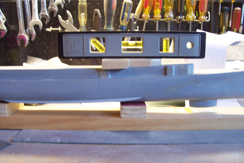
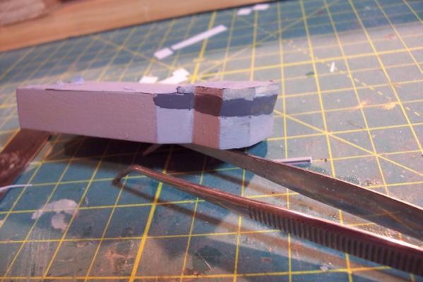
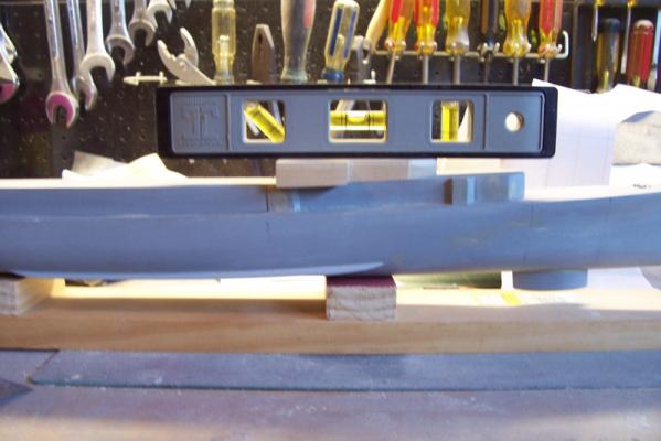
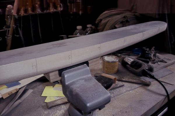
Shaping the superstructure As I mentioned earlier, the superstructure is made up of several sections, each of which is made up of pieces 3 of laser cut wood, topped with a laser cut sheet plastic deck. The shaping involves sanding their bottoms by placing sandpaper on the main deck so that they match the camber of the deck (minimal) and, more importantly, so that their heights are tapered correctly. The aft section tapers from aft to forward, i.e. the aft end is higher than its’ forward end. When done its’ top deck should be parallel with the keel. The forward superstructure assembly also tapers from aft to forward but its taper is greater to allow for the shear (rise) of the deck as it approaches the focsle. Wood also has to be removed aft so that its aft end is the same height as the forward end of the aft section. When done its’ top deck should be parallel to the main deck, which in that area is rising. Here’s how mine looks after sanding (gap between sections is exaggerated for clarity, when assembled they will be in contact). The joint between the two sections should be close, but since there was an expansion joint at that location, covered by a hinged plate, I’ll be covering mine up as well. Here’s what the real thing looks like: The next section is what the instructions refer to as the bridge, even though “01 level” is probably more appropriate. This section also has to be tapered aft to forward. At this point I departed from the instructions, which call for putting sandpaper on top of the forward superstructure assembly. Since that section has several areas of unsupported plastic sheet decking I was concerned I would get some uneven contact under pressure so I just sanded it on my work bench, putting more pressure on the forward part to impart the taper. The instructions state that up to 1/8” may have to be removed from the front of the bridge section so that its top surface is parallel with the keel (i.e. level), that was a good estimate – after removing 1/8” mine is now level. Next I’ll be trying a new method (for me) of putting in portholes – one of my consistent problem areas.
- 144 replies
-
- 4
-
-
- basilone
- BlueJacket Shipcrafters
- (and 2 more)
-
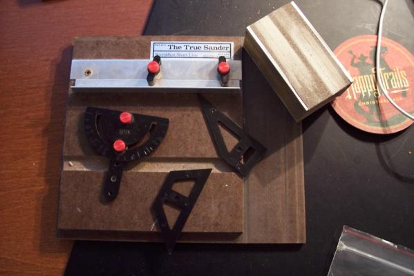
Patrick, I bought this "True Sander" years ago for sanding angles in strip wood for the deck furniture on my first kit. Haven't used it in a long time but it came in handy for sanding the beveled corners of the superstructure. Not sure if they make them anymore.
-
Hey Patrick, That's some motivation you've got starting another build so quickly - I'm usually useless for another build for at least 6 months after finishing one. This is going to be great to watch. I've always wanted to do the MS Connie, in just the way you plan to, but lack of space is an issue. At least this way I'll get the pleasure of watching it come together without having to do any of the work. Kind of like having a personal shopper. Those are some really neat toys you have, wish I had a few. It sounds like you've got all the info you need regarding cannon but since you are working in an odd scale you might find this scale convertor handy, it converts between metric and English and you can plug in any scale you want, might help with after market stuff. http://jbwid.com/scalcalc.htm Looking forward to a great build.
-
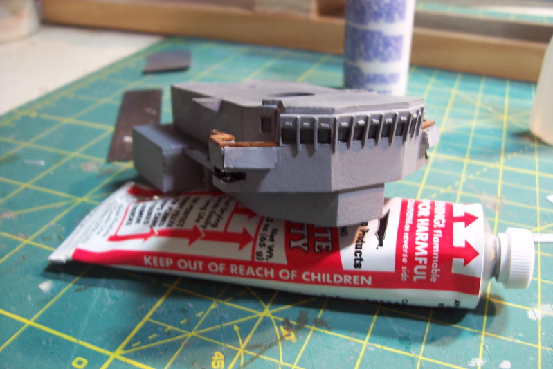
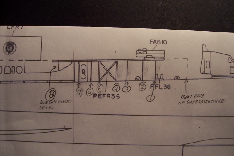
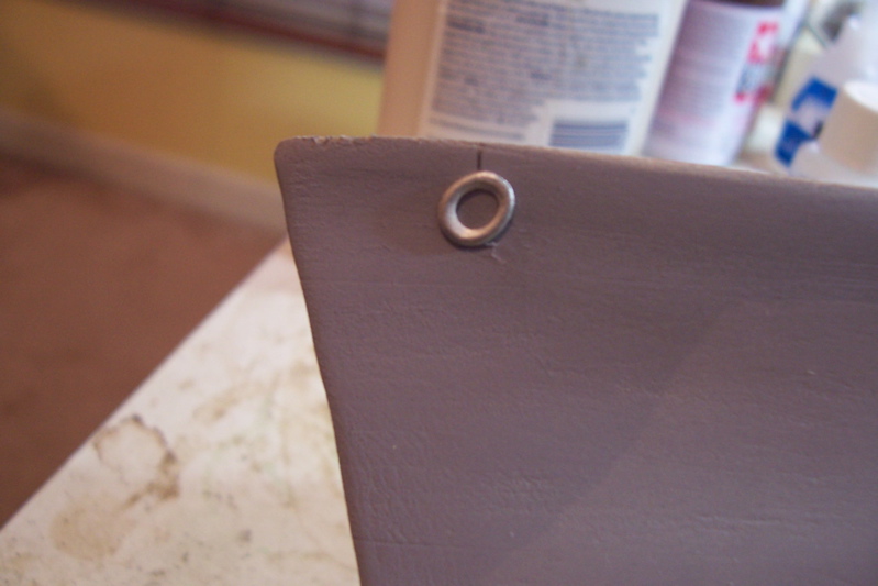
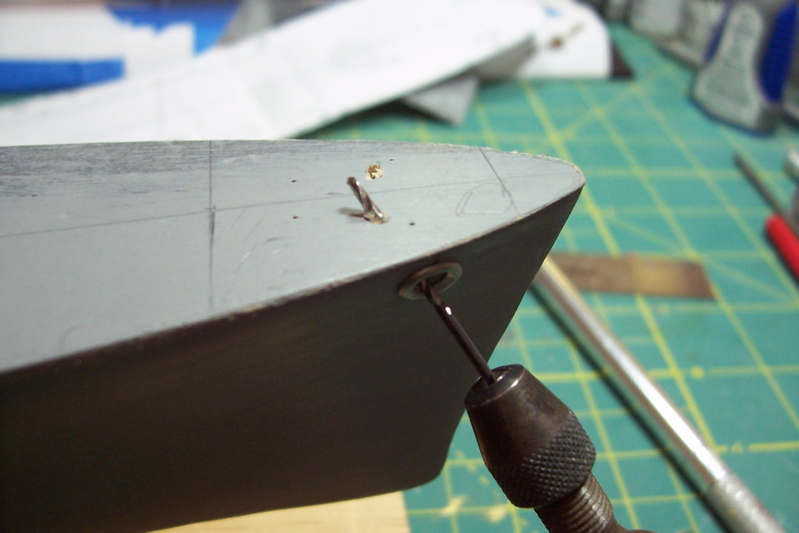
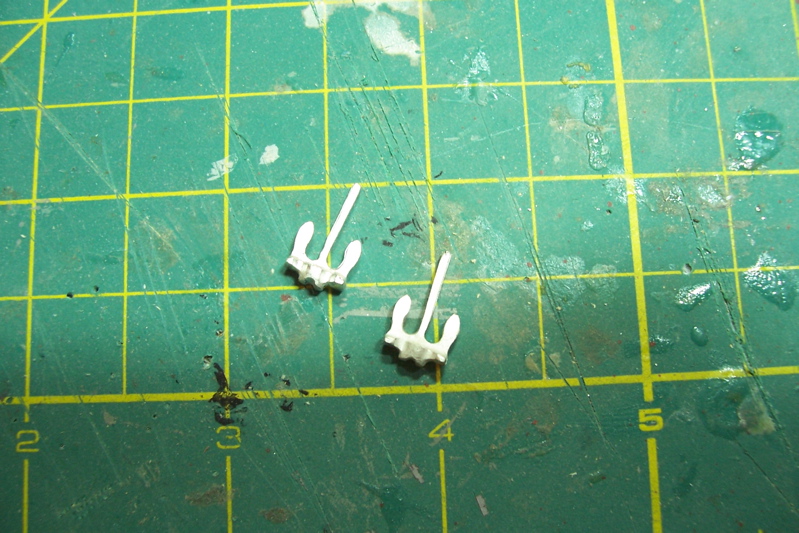
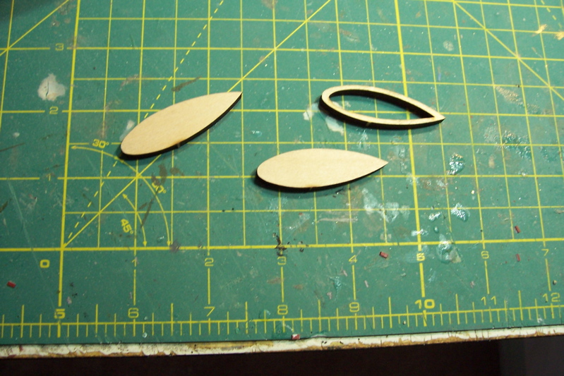
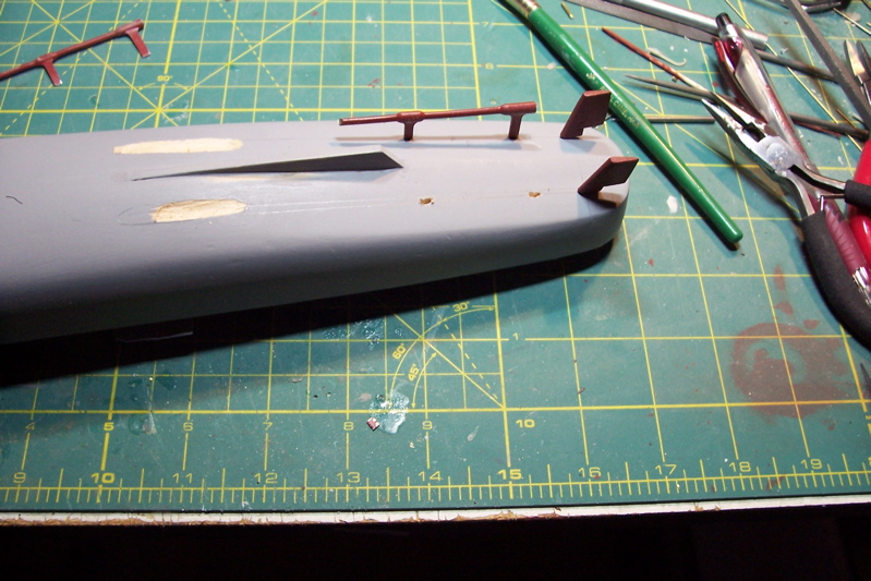
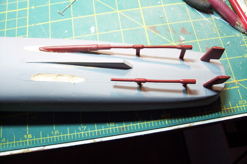
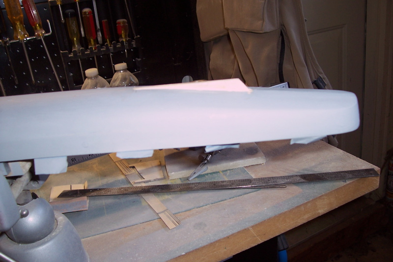
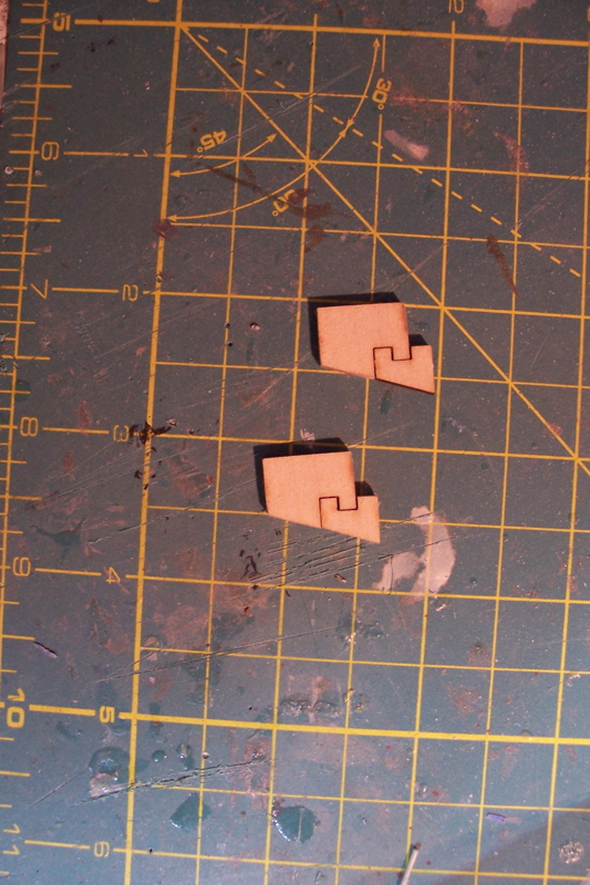
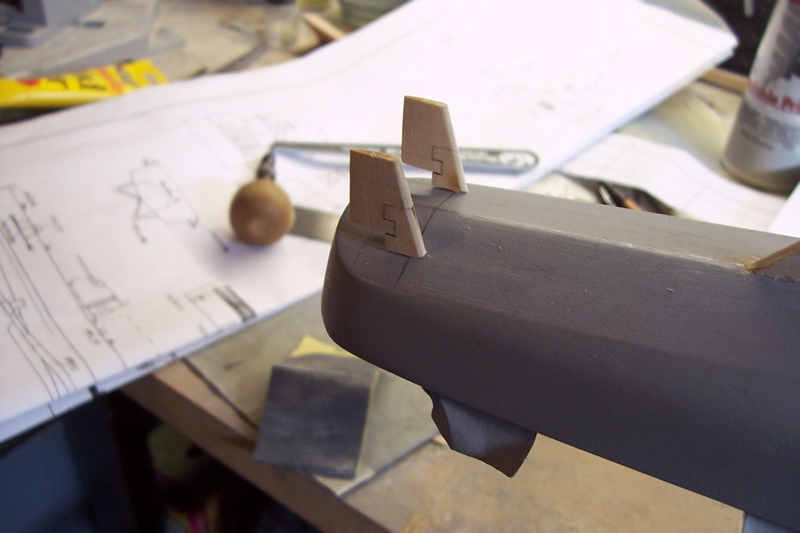
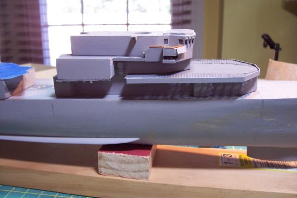
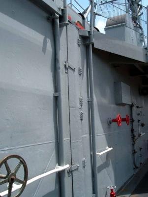
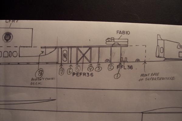
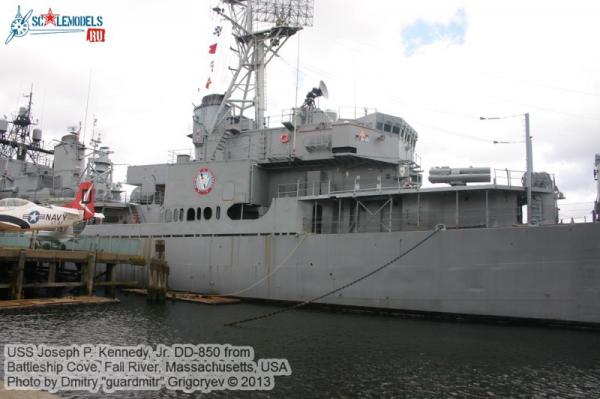
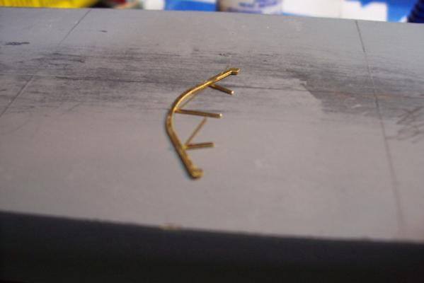
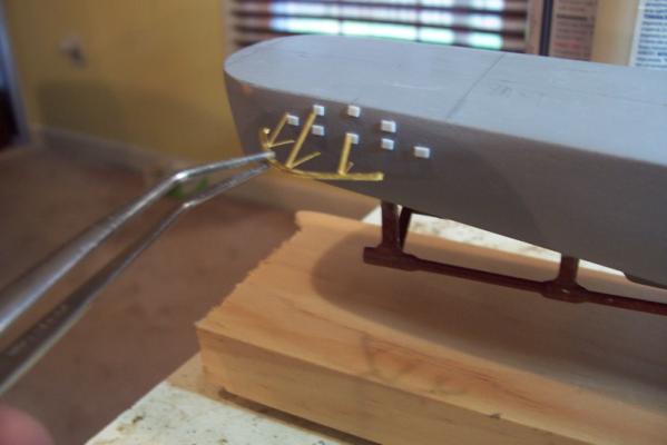
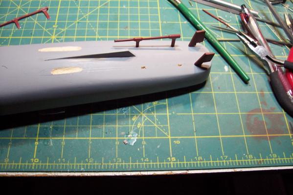
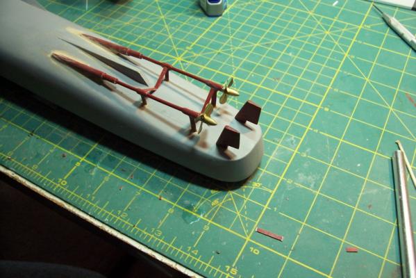
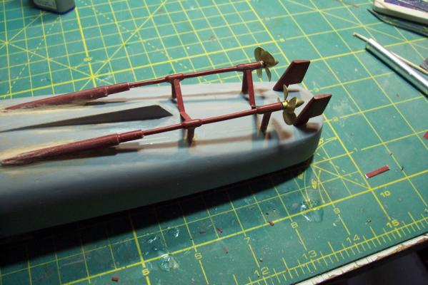
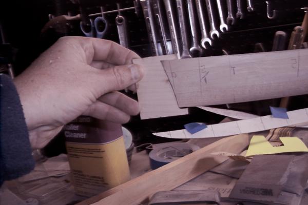
ODDS AND ENDS The instructions call for drilling some locating holes for the 5” gun mounts, davits and some of the superstructure overhang supports. The plans clearly show 7 supports on the starboard side but those are not the ones that need to be addressed now. The ones that the instructions refer to are another set of 7 further forward. They are shown on the plans but are not labeled. The set on the port side will be a mirror image. Unlike the supports further aft these will rest 1/8” inboard of the deck edge, far enough in so that the lifelines will run outboard of them. They are not evenly spaced so consult the plans. Here is a pix of the plans where I annotated the supports, I also included “nr 8” even though it is not mentioned in the instructions it is shown on the plans and in photos of many Gearings. The nr 8 support is different from the others in that it does not extend down to the deck but connects with the bulwark below it. Here’s what the supports look like on the USS Joseph P Kennedy, jr, she does not have the support nr 8 I mentioned because her bulwark design is different. While this may be minutia (but then what isn’t when it comes to ship modeling?), this photo from the JPK show that the 2 supports that have the “X” crosspiece between them have their upper ends resting about a foot further inboard than the others. I’ve seen the same on other FRAM pixs also so I’ll try to incorporate that. The directions call for scratch building a towing padeye per the plans and placing it on the focsle, however the plans don’t show it. Given how small they are I’m not sure putting them on the plans would be much help anyway. I carved one out of wood based on how I remember them looking, and did a second one for the fantail, where it is shown on the Basilone’s plans, since those who would be towed must be ready to tow in turn. The prop guards are made up of 2 identical pieces of PE that are glued together along the curved surface (only!) and then the “legs” are peeled apart. The directions call for drilling mounting holes for each leg and that is probably a good idea because that is the most secure way to mount them but in the spirit of making things as hard as possible I decided to simulate the welding pads they used. I’ll trim the plastic pads after mounting the guards so they hopefully will look something like this: I’ve started fabricating the big superstructure pieces. Just like the sonar dome they are made up of 3 pieces of laser cut wood, the bottom one being somewhat hollow. The aft structure is almost a rectangle and was easy to sand. The forward one is more complex , I found that sanding sticks and files worked best on that one. Note: I'm adding this paragraph and the following picture about 5 months after making this posting. The reason is I discovered an error in the kit and wanted to explain how to fix it for those who might build this kit. The problem is that one of the fan rooms, which are shown as projections on the superstructure piece on the right above, is in the wrong location. Specifically the second one on the port side (counting from the forward end) is about 1/2" too far forward and should be slightly longer. The error is apparent when comparing the part and the kit drawing with the USN blueprints. This is not a major problem (after all I went 5 months without noticing it and only discovered it while planning out the locations for some scratch detailing) so unless you are compulsive about accuracy you could skip this since this area will be behind a breakwater which will help hide it. If you do want to fix it now is the time in the build to do so, it is easier than doing it after the upper deck is attached like I had to do. All you have to do is saw it off with a razor saw and relocate it further aft in accordance with the blueprints. Since I couldn't saw mine I had to sand and chisel it off and then rebuild it using plastic sheet. Here's what the new one looks like before painting: Next up will be priming and finish sanding the superstructure pieces and then sanding their bottoms to match the main deck.


- 144 replies
-
- 5
-
-
- basilone
- BlueJacket Shipcrafters
- (and 2 more)
-
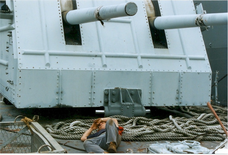
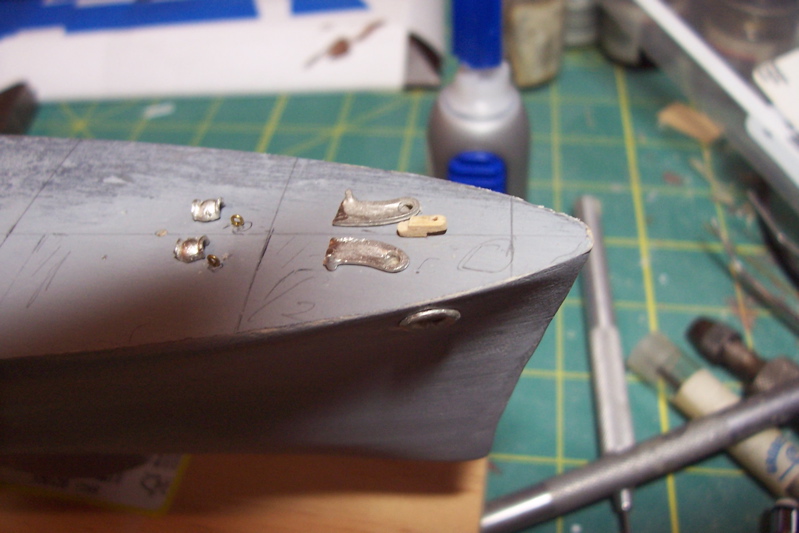
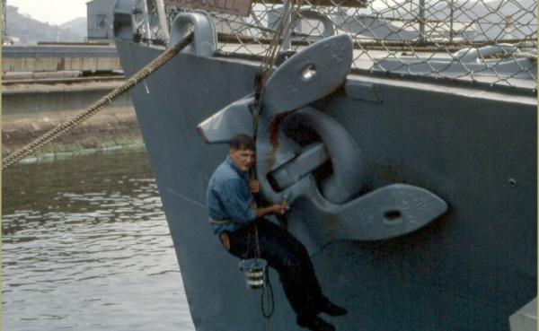
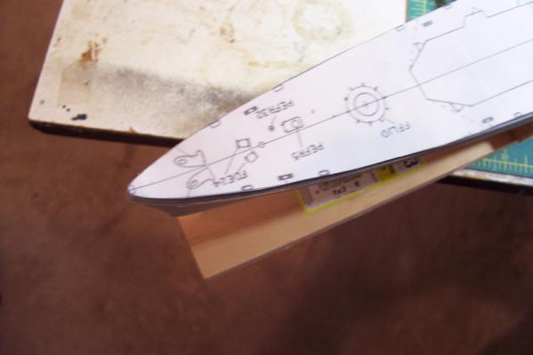
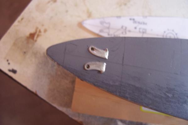
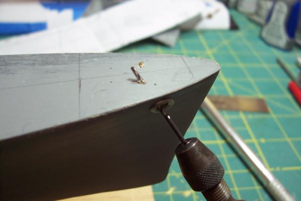
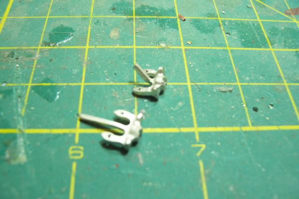
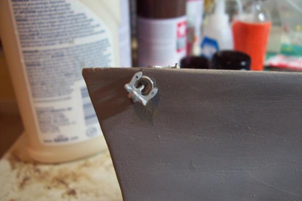
Anchor Hawses The first topside job is to fit the anchor hawse pipes. The hawses consist of 2 pieces pf Britannia cast metal; the hawse lips, which are the portion on the outside of the hull, and the hawse pipes, which are on the main deck. Don’t get too aggressive when filing off flash from the hawse pipes – the upright pin on them should remain, it’s called the bolster or bitt. The hawse lips are oblong and one end is thicker than the other. The thicker end is placed on the bottom and, although the plans don’t show it very clearly, the lips are glued on at a 45-degree angle, which matches the angle that the anchor will rest on them when it is housed. This picture shows what I mean, in addition to showing a disillusioned young man in the process of discovering that the Navy’s recruiting slogan “Navy: It’s not just a job it’s and adventure!” isn’t always true – sometimes it’s just a job. Note also the holes in the anchor flukes – I’ll be adding those to the kit anchors, not in some OCD lust for detail (that will come later) but because they will be used to tie off the anchor bouy for each anchor. The hawse pipe locations are marked on the deck (using a copy of the deck plan and some pinpricks into the deck) and a 1/16” hole is drilled down and angled toward the hawse lips (don’t go too far). Then the drill bit is placed in the hawse lips and drilled up toward the deck until in intersects the 1st hole drilled. A rat tail file is used to enlarge this hole to correspond with the size of the lips. The anchors come with long stocks. It is really hard to fit them so that they poke up thru the hawse pipe – I’m not going to do that since on a real ship they are barely visible in the hawse and I don’t want to have to attach a shackle on the end. I’ll just put the end of the anchor chain down the hawse pipe and trim off some of the anchor stock. Here are my modified anchors with the stocks trimmed and bent to fit (the stocks on real anchors of this type pivot at their base) and the holes drilled. And the anchors dry fitted. I’ll leave them off until later because it is too easy to damage them while handling the hull.


- 144 replies
-
- 6
-
-
- basilone
- BlueJacket Shipcrafters
- (and 2 more)
-
Don, thanks for the pix!! That is a gorgeous build, way beyond what I could do. I was particularly impressed with you sheet brass work, your scratch inclined ladders and your radar antennas. Your album virtuosity is also clever, I really enjoyed just sitting back and watching the slide show of the build pix Thanks again
- 144 replies
-
- 1
-
-
- basilone
- BlueJacket Shipcrafters
- (and 2 more)
-
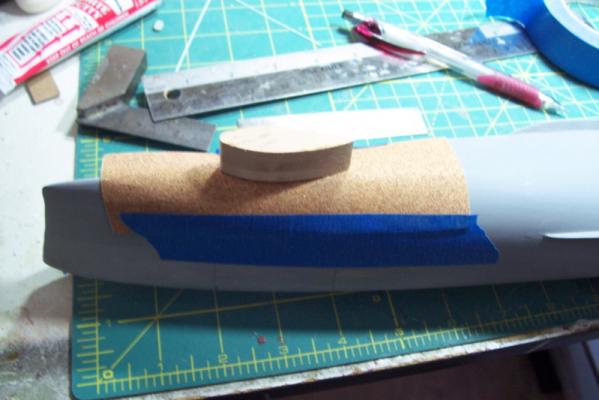
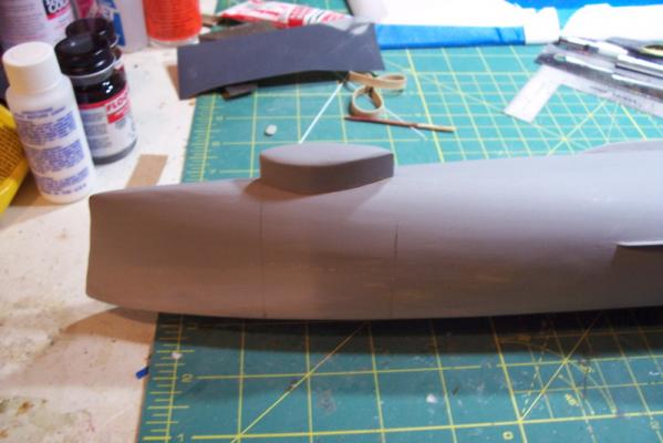
Sonar Dome This is an easy part – adding the sonar dome. The Basilone carried an SQS-23 sonar which was a big improvement for its time. It was the first sonar with a rubber window in the dome and was supposed to be able to bounce active transmissions off the ocean bottom, although conditions for that to be able to work were very rare. When I served on ships with later, more powerful sonars we called to the SQS-23 the “Helen Keller sonar” although to be honest, compared to submarine sonars ours wasn’t much better. The dome comes in 3 laser cut parts, the hollow piece goes against the hull. It’s hollow to reduce the amount of surface area that must be sanded to conform to the hull. After stacking them and gluing them together they are placed on a piece of sandpaper taped over the hull where the dome will fit and its easy to sand it to fit. After that the dome bottom is rounded and then it is glued to the hull. When the hull underbody is painted red later most of the dome will be painted black to simulate the rubber window. Now that this is done I can remove the vise block, turn the hull right side up, attach it to a building board and start working on things that are not almost "out of sight - out of mind" like all this underwater stuff is. That’s enough for now – time to go see if the trout are biting.

- 144 replies
-
- 4
-
-
- basilone
- BlueJacket Shipcrafters
- (and 2 more)
-
Thanks Patrick and Scott for the kind words. Patrick – if you like that poster there are a million more at www.despair.com Having spent too much time in offices and conference rooms where those “motivational” posters abound, finding that website helped me suppress the gag reflex everytime I saw one.
- 144 replies
-
- 1
-
-
- basilone
- BlueJacket Shipcrafters
- (and 2 more)
-
Hi Patrick, I wouldn't call it a practicum but if it helps anyone, even to avoid my mistakes, then it's worth it

- 144 replies
-
- 2
-
-
- basilone
- BlueJacket Shipcrafters
- (and 2 more)
-
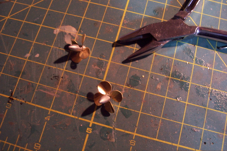
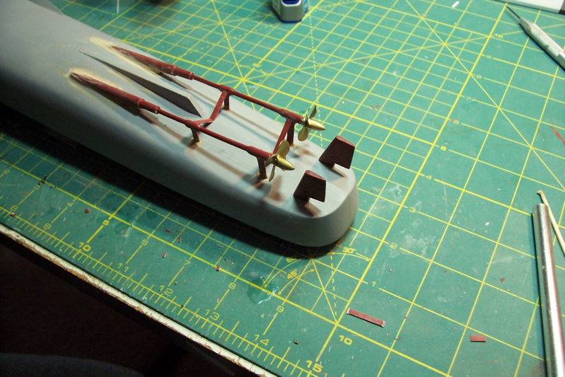
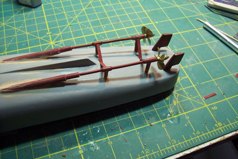
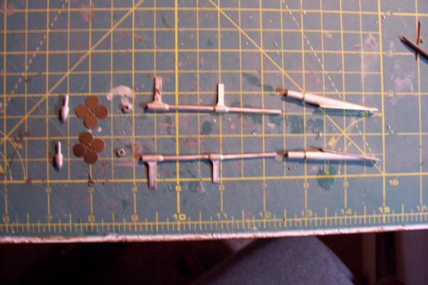
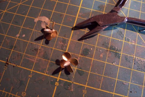
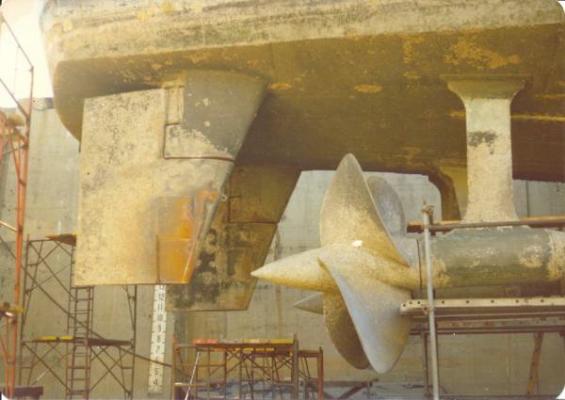
PROPS AND STRUTS The prop blades are made up of PE brass, the hubs, collars struts and shaft bosses are cast Britannia. The instructions call for making the props quite a ways further down the road but I’m doing them now to prevent a potential problem that I will explain in a bit. The prop parts fit together well. Twisting the blades to provide a right and left hand prop is easy enough but giving the blades the proper pitch (curl) is a little more tricky. Fortunately I have a set of four metal forming pliers that I got from Micro-Mark, one of which made this step easy. After marking the axis’ of the shafts, checking them against the rudder post locations, and marking the locations for the struts slots are cut for each strut. The shaft bosses (the shaft tube where it penetrates the hull) now have to be fitted so that they mate with the shafts, keep the shafts at the right angle, and most importantly – maintain their axis parallel with the axis of the struts so there are no “bends” in the shafts. By a combination of filing on the boss bases and getting them lower to the hull by removing some wood below them everything finally lines up. When planning this section I had to stop and think “How can I possibly screw this up?” The worst scenario would be to get ready to add the props right at the end of the whole build and find they didn’t fit – that’s why I made them up now. The final check before everything is glued in place is to dry fit everything to make sure that the screws have adequate clearance longitudinally to the rudders and vertically to the hull. After gluing the bosses and shafts in place strip plastic is cut to size to make up the inner shaft struts. I gave everything a preliminary coat of red so that when I get around to spraying the hull underbody I won’t have to try to reach the back sides of this stuff. The props will be removed and stored in a safe place until they are added just prior to casing the model. They are very fragile and would be easy to damage during the build if left on the model. Next up will be building the sonar dome.

- 144 replies
-
- 9
-
-
- basilone
- BlueJacket Shipcrafters
- (and 2 more)
-
Thanks Patrick, I appreciate the compliments.
-
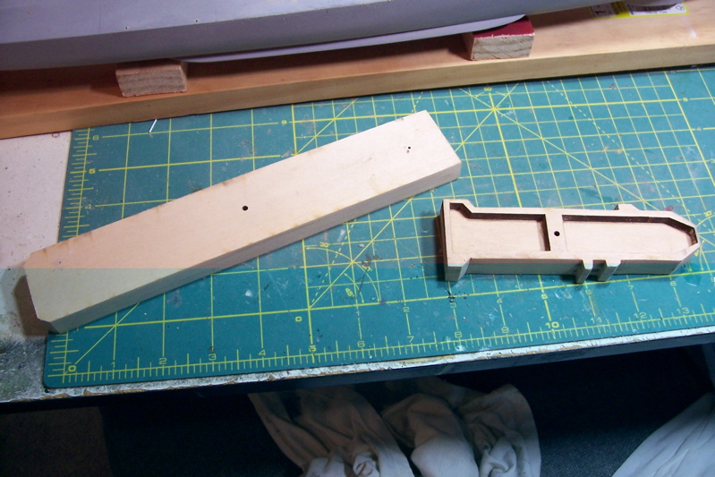
ADDING THE BILGE KEELS The bilge keels’ location is marked on the hull and a 1/16” wide by 1/16” deep slot is carved using a hobby knife and a file. The keels themselves are fabricated from stripwood, tapered at each end and sanded to a knifedge on the outer edge. After a lot of adjustments the keels fit into their slots. The bilge keels’ function is to help reduce rolling in a beam sea and provide stability during turns. Next up will be fitting the struts and, temporarily, the props
- 144 replies
-
- 4
-
-
- basilone
- BlueJacket Shipcrafters
- (and 2 more)
-
Took a break earlier this week to go out to the National Archives facility in College Park, MD in order to look at the plans for the Basilone. It was well worth the trip because the Basilone had several differences from the Gearing and the plans at the NA are more detailed than what I got from the Floating Drydock. Anyone who is thinking of building a model of a post-1880 USN ship and lives within comfortable driving distance of Washington DC may want to think about taking a trip out there. They do have more rules and procedures than the TSA but they are all laid out on their website – as long as you know what to expect it’s no big hassle. They do have a search function on their website that will tell you what they have available on your ship. Another modeler who built this kit ordered the plans from the NA but the cost was several hundred dollars. If you go there they will print them out for you on paper there but it is still $3.50 per linear foot, given that each sheet of plans is about 5 ft long that is still pretty pricey. They will digitize the plans on a CD for you for about $3 per sheet. Since I only needed 4 that was about $11. I then took the CD to a local blueprint service who printed them out for me for $10. So for about 20 bucks I now have clear, detailed plans to support my build. ADDING THE SKEG AND RUDDERS After shaping the hull I finally was able to stop doing subtraction and begin to do addition. The first thing to add was the skeg. After marking the location on the hull, some burr head fittings in my Dremel made quick work of excavating a trench for the skeg to sit in. The rudders are made up of 2 pieces of laser cut wood. After joining them they are sanded to an airfoil shape. The joint between them should be maintained and not filled in or covered with too much paint because it represents the junction between the fixed and moving parts of the rudder and is visually prominent. I dry fit the rudders to the hull to use as a reference point for placing the propeller shafts. Next step will be fitting the bilge keels.
- 144 replies
-
- 6
-
-
- basilone
- BlueJacket Shipcrafters
- (and 2 more)
-
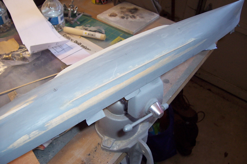
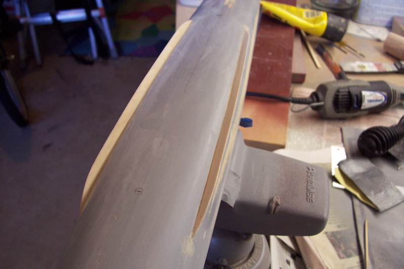
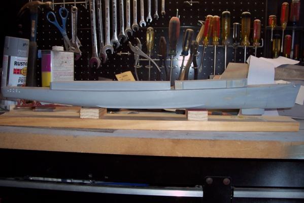
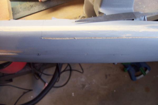
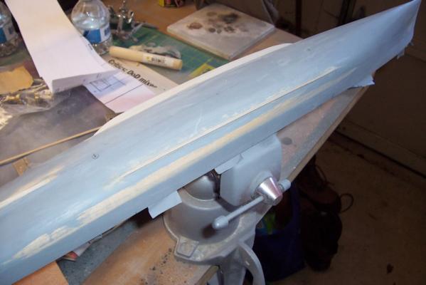
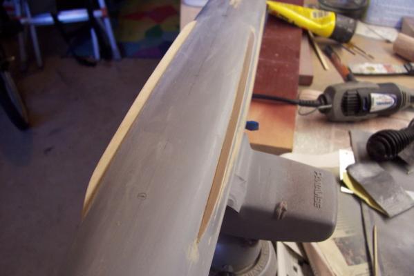
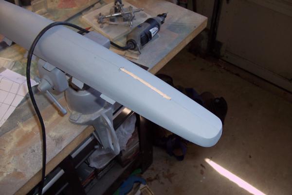
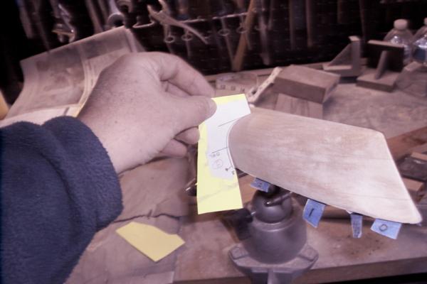
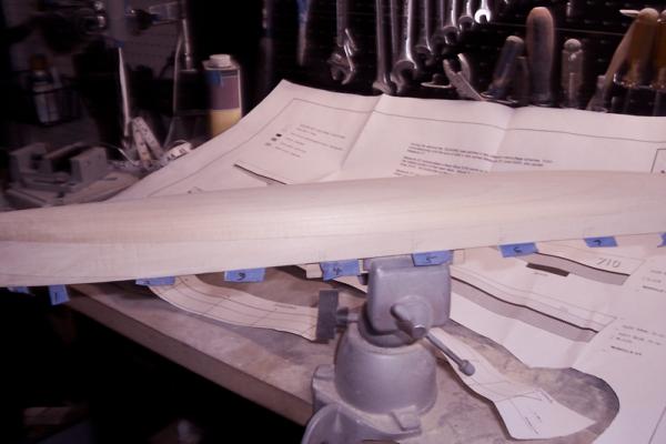
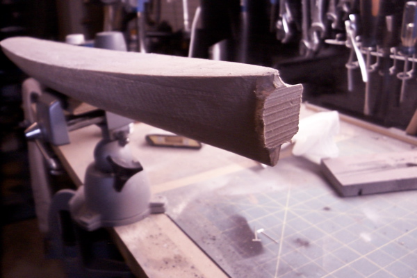
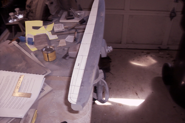
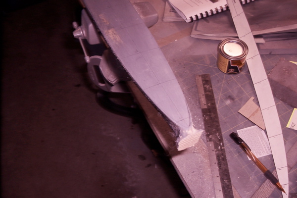
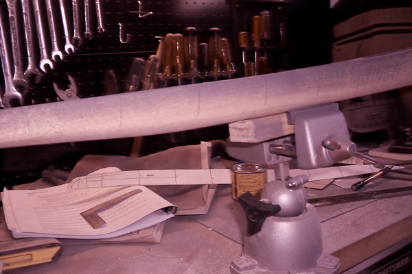
SHAPING THE HULL Shaping the hull using mainly sandpaper and occasionally files, and very occasionally a Dremel is for me the most tedious part of the build. Having removed the machining plugs on the bow and stern and marked the hull with the template stations, the hull is now ready for shaping. I started out by bring the bow into its proper profile, as viewed from the side, mainly using files, and verified by a laser-cut template provide in the kit. The gap at the bottom of the template is not a problem, the same gap appears when the template is layed on the plans so the height of the bow is OK. After that I started working my way aft checking 2 or 3 stations at a time to see where the wood needed to be removed and then sand, sand and sand some more. If you have never worked on a solid hull my recommendations are: Always use a sanding block, freehand doesn’t give you the control you need and it’s really tough on your hands Use long strokes in a fore and aft direction, that will help keep the hull lines fair between the stations Alternate your sanding on the port and stbd sides, don’t try to do one side then the other Be careful near the deck edge, you want to keep a sharp edge (another reason for using a sanding block) Avoid power tools except where you can easily tell what needs to be removed, in this case I only used a Dremel to remove the machining plugs. Power tools can quickly remove too much material and lead to an uneven, wavy surface. Also resist the temptation to use sandpaper any rougher than about 100 or 110, sure it will go faster but it may go too fast, and ending up taking off more than you want Keep checking your progress using the templates, check both sides and 1 or 2 stations “further down the line” in the direction you are working. The hull doesn’t make any radical changes in shape between stations so you need to keep cognizant of how it will change as you progress If you need to impart a curved surface into the hull, like I did to give the bow some flair, and some slight concave areas above the screws, then wrapping the sandpaper around a round object of the appropriate radius will do the trick. Take your time. I find this kind of work mind-numbing so I only do it for 10 or 15 minutes at a time or I get sloppy Since the furthest forward template station is a few scale feet aft bow, there is no indication on the plans of just how narrow the cutwater should be. I found some photos online, like the one below, that indicated the bow was rounded right under the forward-most enclosed chock (the “Bullnose”) but then narrowed to a knife edge just 2 or so feet below A few words about the wood, I'm 99% sure it is Basswood. It sands easily but keeps a sharp edge where needed, it doesn't produce any "fuzz" so I didn't need to use any sanding sealer or wood hardener and it seems free of any oil so it takes spray primer well. After about 5 hours of sanding spread over 3 days the hull is now in its final shape. Next step will be to give it a fine sanding using 400 grit sandpaper, then prime it to highlight any rough or uneven spots, sand or apply filler as needed and then repeat the whole process until the hull looks like metal rather than wood.
- 144 replies
-
- 7
-
-
- basilone
- BlueJacket Shipcrafters
- (and 2 more)
-
Thanks Bob, hopefully this one won't take me near as long to build as the Olympia did, but then again, that one was before I took up fly fishing so it could be even longer.
-
Thanks Patrick, glad to have you aboard. Congratulations on your Niagara, she is the best I've seen. You did a spectacular job on the woodwork, painting and rigging - first class all around! The Niagara kit is one I've been mulling over for a long time, seeing what you have done with it may push me over the edge. If you haven't already, you might enjoy looking up the history of what O.H. Perry had to do to build the Niagara and the rest of his squadron. It's amazing what they were able to accomplish in such a short time, given that every nail, rope, cannon (and flag) had to be dragged across hundreds of miles of roadless wilderness. It was just as hard, if not worse, for the Brits on the other side of the lake. Of course the price paid for building with green wood in a hurry was that all of the ships were rotted wrecks within 2 or 3 years of the battle, but they had served their purpose by that point.
- 144 replies
-
- 1
-
-
- basilone
- BlueJacket Shipcrafters
- (and 2 more)
-
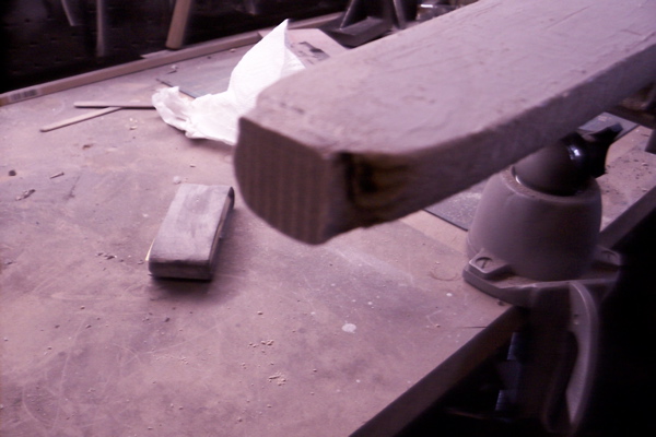
PREPARING THE HULL FOR SANDING AND SHAPING The instruction books starts off with a cautionary note that due to varying manufacturing and environmental conditions the plans may differ in size from the Mylar masters they were made from. Several reference measurements from the bow to key items like the gun mounts and the front of the superstructure are provided in case there is some discrepancy. The length of the hull on the plans should be 24 7/16”. My plans measured out only 1/32” over. Since that is well within my personal margin of error resulting from clumsy fingers, aging eyes and poor technique I think I am good to go. After mounting a temporary vise block to the keel, the hull is ready to mark up. The next 2 photos show the machining plugs on the bow and stern that will have to be removed. Once the deck has been sanded smooth the centerline is measured and marked. Using the centerline as a guide, the deck template is laid along it and the outline of the deck edges are marked and the locations (stations) for checking the hull shape using templates. (Sorry but the pencil marks don’t show up very well on deck against the dark grey primer I used to check for rough spots). I told you earlier that the rough hull comes out of the box very close to its’ final dimensions. Using the deck profile template as a guide it looks as if no more than 1/16” will have to be removed from some areas of the sides, in some areas virtually none will have to come off. Finally the hull template station marks are extended down the sides of the hull. As the hull is shaped they will be sanded off and will have to be reapplied several times. Now the hull is ready for shaping. The bow and stern plugs will be removed first, then the sides will be sanded to match the deck edge profile. After that is done the vise block will be unscrewed from the keel, the hull inverted and the vice block attached to the deck. The shaping of the hull will continue using the templates.
- 144 replies
-
- 8
-
-
- basilone
- BlueJacket Shipcrafters
- (and 2 more)
-
Nick and S.os, Thanks for the replies. I thought this would be a good subject for a build log since there are few "metal" ships included or solid - hull kits. The main reason I'm doing the log is to help keep myself on task since it will be very easy to be distracted as the trout streams around here start to warm up. Tim
- 144 replies
-
- 1
-
-
- basilone
- BlueJacket Shipcrafters
- (and 2 more)