
Supplies of the Ship Modeler's Handbook are running out. Get your copy NOW before they are gone! Click on photo to order.
×

jud
-
Posts
1,171 -
Joined
-
Last visited
Reputation Activity
-


-
 jud got a reaction from CarolinaCommodore in Cannon Hatch Cover
Having been around large guns on ships and seen the damage shock waves from Muzzle Blast can do, my guess would be that those with experience would secure them up against a stopper or held hard against the hull so they could not move when the guns were fired. Suspect most will tell you to leave them out because that is what they have seen in models for years. Hard against the hull or against a stopper will get you more disagreements than leaving them to flap in the wind as is the norm in the modeling world when they are modeled on the hull. Seems like those upper covers were removed and stored below when exercising the guns, probably experience dictated that solution.
-
 jud reacted to shipaholic in Question about stern planking for OcCre HMB Endeavour
Hi Umberto
There is a piece blocking the rudder at this stage, indicated by the arrows below, it is enclosed by the two pieces no. 57
Later on in the build you are required to drill that section out with a 4mm drill to be able to insert the rudder post
Cheers
Steve
-

-
jud reacted to wefalck in Proud owner of a Dremmel drill stand
The old machinists' rule something should not stick out of a chuck more than 3 to 4 times the diameter. With stiff material, such as certain steel you may be able to go safely to 5 or 6 times the diameter. This applies to wood as well, but it also depends on the absolute diameter.
The reason is the run out that can dramatically and suddenly increase when you are working on a part, due to the sideway pressure you are applying.
The consequence is, that you have to support longer parts at the other end - in a so-called tailstock or a so-called fixed steady. I would imagine that it would unnecessarily difficult to device a tailstock or steady for the hand-held drill mounted in the drill-stand. If you want to go that route, it is much easier to take a long board, figure out a sort of clamping fixture for the drill and a steady or tailstock at the other end. Much more stable, than the drill-press.
There are examples here on the forum and elsewhere on the Internet. A classical example, that has been up on the Net for 20 years is this: http://www.lathes.co.uk/fonly/ (Government Health Warning: Don't look at the other pages of this Web-site, they make you drool ...)
-
 jud got a reaction from thibaultron in Unloading cargo from tall ships
Is the Crain going to still be there tomorrow? Lightboy, USS Clark County LST 601
-
jud got a reaction from thibaultron in Unloading cargo from tall ships
Liberty Ship SS Stephen Hopkins by schooner posted yesterday has a link ' http://www.globalsecurity.org/military/library/policy/army/fm/55-17/ch3.htm', showing cargo rigging. Illustration 3-17, Strain Angle of Falls is well worth studying. The physics has never changed from the early days of sail until today, some of the forces probably will come as a shock to some.
jud
-
jud reacted to el cid in Carriage Gun Rigging
This from page 42; it seems closing the gun ports between shots was situational, perhaps as a ship rolls or comes about in heavy seas?
-
jud reacted to mtaylor in Carriage Gun Rigging
While it is a good reference, one must check for dates and nationality as things changed and varied by country (including the duties and numbers of the gun crew) over time. But overall, it's a good document and can help understand how the guns were manned and served.
Thanks for posting this Phil. I'll bookmark for future reference.
-
jud reacted to Dr PR in Carriage Gun Rigging
This is a rehash of much I have found on the forum and possibly some new information. I have seen discussion of how to model the rigging of carriage guns, with lots of speculation. I hope to condense this a bit here.
Here are some drawings of British and American gun tackle and breeching lines. The breeching lines are attached to ring bolts on the bulwarks and are attached to the cascobels at the rear of the cannon. In some cases they are wrapped around the cascobel as shown at the left. Sometimes they were attached with a cut splice that fit around the cascobel, as shown at the right. Later guns had a breeching ring cast into the barrel above the cascobel, and the breecing line passed through it. The breeching line stopped the recoil of the gun when it was fired, preventing it from crashing about the deck. It was roughly 1/3 the diameter of the shot, and was long enough (3 times the length of the cannon bore) to allow the cannon to move about a foot or two inboard of the bulwark to give the gun crew room to swab and load the cannon. There were very specific methods of attaching the breeching lines to the bulwark ring bolts, normally using seizing of small line wrapped around the breeching line.
The gun tackle (outhaul tackle) hooked to a ring bolt on the bulwark, and hooked to a ring bolt on the gun carriage. The gun tackle was used to haul the gun out to the battery (firing) position after it was loaded. This tackle for larger guns consisted of a single block hooked to the gun carriage and a double block hooked to the bulwark. Smaller guns might just use two single blocks. A "loose end" (pun intended) in the descriptions of the gun tackle is what to do with the falls (loose ends) of the tackle? The line leading from the block attached to the bulwark had to be long enough for the gun crew to grab. Then when the gun was hauled to battery and the blocks came together, more line, 3-4 times the longest distance between the blocks when the gun was in the loading position, was pulled out of the tackle - that is a lot of line. Typically drawings just show the falls going off somewhere. What did they do with all of that line?
I have seen four variations for dealing with the gun tackle falls. The picture on the left above shows the loose ends "frapped" (wrapped) around the tackle. However, most of the falls was taken up by looping it a few times through the rings on the hooks at the bulwark and gun carriage, with the remaining part frapped around the bundle of lines. This would have been used to secure the guns when they weren't being used, in port or at sea. Note the breeching loop cast into the rear of the cannon.
The picture right above shows the end of the falls "Flemished" in a tight spiral on the deck. Many models use this method because it is a simple way to deal with the loose ends. However, on real ships this was done for show only, during inspections or ship visiting days. There is no way this would have been used at sea! The loose ropes would be scattered all over the deck, and this was not good!
Another way to secure the gun tackle loose ends that I have seen was to belay the line around cleats or belaying pins on the bulwarks. This would be a "ready stowage" solution to keep the ropes from flopping around the decks and getting tangled while approaching a battle. But it could also be used when the guns were secured. Another method was to just roll the line into a lose coil and place it on the deck near the bulwark block. Again, this would have been a temporary stowage while preparing for battle.
In battle the falls would have been pulled taut straight back from the block along side the cannon by the side tacklemen, and perhaps faked down on deck for long falls. When the gun was fired the line ran cleanly through the block - the tackle absorbed some of the recoil momentum. Note: Not everyone is happy with this explanation - see the references below to support my reasoning.
****
The training tackle (inhaul tackle) was similar to the gun tackle. It hooked to a ring bolt at the rear of the gun carriage and to another ring bolt mounted in the deck some distance behind the gun. The training tackle was used to haul the gun back inboard to the loading position. Some ships used a single training tackle, others used two training tackles (only the heaviest guns >= 36 pounders had two training tackles), and you often see pictures and drawings where no training tackle is used. What did they do with the training tackle when it wasn't being used? Apparently it was stowed with all the other gun handling gear, often on the bulwarks between the guns, at least while they were preparing for battle. When the guns were secured all the loose paraphernalia was probably stowed below.
This drawing shows a Continental (French, Dutch, etc.) style gun. First note that the breeching line passes through a hole in the gun carriage, and it does not attach to the cannon. It serves the same function, to stop the recoil, and it must be long enough to allow the gun to move inboard at least 1/3 meter for loading.
The drawing shows the gun in a stowed position with the end of the barrel raised (with the quoin removed) and pulled tightly against the top of the inside of the gun port. This was common in all navies, but there were probably as many variations as there were ships. The tackle was used to draw the gun tight against the bulwark, and lines were frapped to take up slack. Chocks were also used to secure the gun. The last thing you wanted was a loose cannon rolling around the decks in heavy seas!
The answers to many of these questions are found in Ordnance Instructions for the Unites States Navy (1860) which can be downloaded here:
https://archive.org/details/ordnanceinstruc00ordngoog
Gun and train tackles were not removed before the gun was fired (pages 45 -47)! Up to the Ready/Fire commands the side tacklemen held the falls taut. At the command "fire!" side tacklemen dropped the tackle and falls and let them run to slow the recoil. The train tacklemen pulled on the falls to take up the slack as the gun recoiled, and then held the gun until it was loaded. However, the train tackle could be unhooked before firing in calm seas and then attached after recoil.
Note: The text describes when the gun tackles are hooked to the bulkheads and to the rings on the gun carriage, and which of the gun crew does each task. It never mentions unhooking the gun tackle until the gun is to be secured and stowed. In the drawing below the gun tackles and training tackles are attached in the firing position.
The gun was pointed by hauling it in to the extent allowed by the breeching line, and then one or the other side tackle was hauled in to swing the gun left or right (page 46). Here is a diagram showing pointing, firing and loading:
Breeching must be long enough to allow the gun to clear the gun port at least one foot when hauled fully inboard. Neither breeching nor tackle can be blackened or treated in any other way that reduces flexibility. They are to be made of manila or another pliable rope. (page 150).
I haven't read it all, but I couldn't find any description of how the gun tackle falls were to be secured/stowed when not in use. However, at the command "cast loose" the tackles were to be removed from stowage and then hooked to the bulwark and gun carriage. So maybe they were not hooked to the guns while they were stowed? Or were the frapped tackle considered "stowed?"
****
As far as placement of the ring bolts for the gun tackle on the bulwarks, the diagram above shows the attachment points spaced far from the gun port to allow a significant angle of pull on the tackle for pointing the gun. But most photos and drawings do not show them as widely spaced as in the drawing above. I have also see (somewhere) a drawing showing double ring bolts for the train tackle on the bulwarks, on each side of the gun port, spaced fairly close together, in case one bolt fails.
In the description of how to point the gun it says the gunners used the handspikes to lever the gun left/right to assist the tackle. So it wasn't necessary for the gun tackles to be spaced widely as shown in the diagram above. The tackle could be used to hold and fine tune the point. The handspikes were also used to raise the breech to free the quoin so it could be repositiond to change the gun elevation.
One other detail I had been wondering about - the port tackle (for the gun port lid) was secured to a cleat on the inner top of the gun port. The door/lid was to be raised high to prevent damage from the blast of the gun. After each shot the port lids might be closed to provide protection for the gun crews while they were reloading.
****
There is a lot of useful information in this document. It was written in 1855 and amended in 1860, but gunnery practices probably had not changed much in centuries except as new gun types were introduced. The referenced text describes practices for smooth bore muzzle loading guns.
****
I hope this is helpful, and that it will stimulate further discussion.
-
jud reacted to Roger Pellett in Anyone use a 10" table saw for detail fine wood cutting?
My 10in Delta Contractors Saw is my go to tool for all ripping. I have a lifetime supply ship model quality hardwood in my stash (If I run out, I'll consider my self fortunate!) so I'm not concerned with saw kerf. Relative to other woodworking activities that I've engaged in during my lifetime, dust is not excessive, although I just modified the saw to collect it.
The Sears Kromedge Thin Rip Veneer blade described by Snug Harbor Johnny above was the blade used by modelers like Harold Hahn before availability of the Preac and Byrnes minirature saws. I still have a couple and they can be found on EBay. There are also many quality new blades on the market that you might consider. I also have and use a Rockler Thin Rip guide that mounts in the mitre groove and eliminates the need to have the thin strips between the fence and the saw blade. IMHO the Rockler guide also makes this potentially dangerous tool easier to use.
I have a Byrnes saw too. For a new prjoject that I am considering I will use the 10in saw to cut leaves from hardwood billets and the Byrnes saw to cut the planks from the leaves, but there is no reason why with the proper setup, zero clearance inserts, and saw blades your 10in saw cannot produce quality ship model planking.
Roger
-
 jud reacted to Keith S in Ships vs Boats
Well, when a ship behaves well in a seaway, sailors say she's a "good seaboat".
I submit the two things are largely synonymous, with the distinction being merely a matter of convention. Of course, an aeroplane or even a spacecraft can be a "ship", and a "liner", but never a "boat", unless the aeroplane in question has a hull: then it's a flying boat, but only if it has one hull, never two. And a helicopter can never be a "flying boat", even if it has a boat hull, like a Sikorski Sea-King. But it can still be a "ship" or even a "liner" if it flies scheduled routes. Gunboats are "boats", even the biggest kind, with commissioned officers on a bridge, and a wardroom and accommodations and a galley and the whole nine yards. Again, an aeroplane or helicopter can be a "gun ship" but never a "gun boat"; it's only the boat one that can be called a "boat"... but only if it's not a FLYING boat. Then it's a "Gun ship".
I suppose if you took the guns off a large gun boat, it would be a small ship. I mean, what else would you call it?
Of course, you can call a small steam-powered ship a "steamboat", but if you change the steam engine for a diesel, then it's a "ship", not usually a "diesel boat", unless it's a submarine or a tug. Or one of those colossal ships that sail in the Great Lakes: those are obviously "boats" whether they're steam or diesel or whatever. As for seagoing ones, you can have "steam ships" but if they're diesel powered they are suddenly called a "motor vessel" even though they all have engines, not motors. Which brings me to the subject of the difference between engines and motors....
-
 jud got a reaction from mtaylor in Frames built vertical or perpendicular to keel?
Gravity is a constant within limited areas so a water level unless effected by friction and wind will always show true at both ends. Plum Bob strings will also hang parallel unless disturbed by air movement within the area of a hulls construction. Those two things provide the repeatable constants for building anything and they are perpendicular. Suspect they, with few exceptions were the only constants in old or current ship building. KISS principle comes to mind.
en.wikipedia.org › wiki › KISS_principle KISS, an acronym for keep it simple, stupid, is a design principle noted by the U.S. Navy in 1960. The KISS principle states that most systems work best if they are kept simple rather than made complicated; therefore, simplicity should be a key goal in design, and unnecessary complexity should be avoided.
-
jud reacted to Bob Cleek in Turning small brass
Zero to negative back rake on brass. Google is your friend. There's tons of tutorials on YouTube. Check out "Mr. Pete 222" or "Tubal Cain" on YouTube. He's a retired shop teacher who's got tons of videos on machining on YouTube. They're great!
You may want to print something like this out and keep it for reference: http://www.steves-workshop.co.uk/tips/toolgrinding/tool-grinding-poster.pdf
-
jud reacted to vaddoc in Frames built vertical or perpendicular to keel?
Indeed Roger. This actually was what the Mediterranean shipwrights were also doing. I have no expertise or knowledge in this matter but what I meant was that, after the frames were produced, whether perpendicular to the keel or waterline or other, these angles still had to be maintained building the boat so the shipwrights would have to know beforehand how the boat would lay for building and how it would go in the water. I assume that those very heavy frames would make sense to keep vertical and not at an angle where they would need pretty substantial support.
-
jud reacted to Roger Pellett in Frames built vertical or perpendicular to keel?
Chapman’s drawings were intended as a survey of hull forms; both to illustrate generic vessel types and more unusual foreign types. Except where he actually shows structural details his projections would be intended to best show hull form, not actual framing.
The waterline is important to Naval Architects as other waterlines drawn parallel, stations drawn perpendicular to it, and especially buttocks based on these projections help them to visualize flow around the hull. On the other hand there is no structural or construction reason why frames needed to be perpendicular to the design waterline.
There is also no important structural or construction reason why frames needed to be square with the keel.
My conclusion: Frames in wooden ships were erected square with the keel except when they weren’t.
-
jud got a reaction from mtaylor in Ratlines knots
Tie the first and last knot with the bitter end tucked under the outside turn making the clove hitch into a constrictor knot. don't pull
tight or trim until the shrouds are adjusted.
-
jud got a reaction from mtaylor in Canvas covers for cargo hatches, 19th century
These are the best of Cargo Hatch Cover Photos I took in 66-67 aboard 2 different 542 Class LSTs in the South China Sea or on a Delta river, except the supply ship that kept us in feed and ammo. The photo of the wet forward hatch taken aboard the Clark County LST 601, a ship I was part of the recommissioning crew 65-66, is over the main deck ramp to the tank deck, on a slope but typically closed as all hatches were that I was ever around. Notice the white water, not here, but green water sometimes got up there, hence the batons over the top from side to side to prevent wind and water from lifting the covers and boards underneath, this was also done on the main deck hatch. I show how those batons were attached aboard the Harnett County LST 821, they were two piece, connected by turnbuckles so they could be loosened to remove and tighten up again when placed across the closed hatch. Included the other photo to show that those closed hatches were often used as deck space, here we are storing empty 40MM Bofors cans in hopes we could offload them before we had to throw them overboard. The cargo ship hatch, is partly open so you can see the boards and cross members, the clips outside the hatches are visible along with a sack of wedges used with the batons and clips to secure the covers.
-
jud reacted to wefalck in Canvas covers for cargo hatches, 19th century
I don't know how it was done on your specific, but in in general metal brackets were fixed along the coaming and the cover fixed with battens that were wedged against the coaming with pairs of wooden wedged driven in from opposing sides.
On the picture below you can see the arrangement on a somewhat later ship around the coamings of the skylight.
http://www.maritima-et-mechanika.org/maritime/models/wespe/Laverrenz-20.jpg
On the sailing ships of old, that would be at sea for months, the battens may have been nailed down in addition.
-
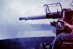
jud got a reaction from mtaylor in Cannon Alignment
Remember that the gun does not move until after the projectile has left the bore so we are not talking about an engine delivering long term and steady force. When the projectile leaves the bore, it's all over folks, no more force attempting to overcome inertia of a stationary mass, what remains is working against the buffer action of the training tackles and whatever constraints the carriage and it's mass bring to bare, all energy absorbing masses and friction devices acting as restraints while absorbing diminishing energy. Bothers me not letting the tackle act as a brake. Recoil up to today is absorbed without harm just as it was done then, more energy today, yep. but time, distance and mass are still the controlling elements used to absorb energy delivered a blow. 6ft/sec means little when dealing with milliseconds absorbed over time and distance.
-
jud reacted to Bob Cleek in Pantograph??
Most pantographs available today are really little more than toys. The really good ones used back when are very complex pieces of precision equipment and rather heavy. If you can find a complete one, it will likely be quite expensive if the seller knows the collector's market.
In practice, the pros used the pantograph to simply mark points from the original to the copy and then "connected the dots." That's much easier than trying to trace lines with the instrument. Using this method, acceptable results can be realized, even with the cheap ones. In most instances, however, scaling is today far easier with a copy machine.
If you find one like this at a garage sale, grab it!
https://americanhistory.si.edu/collections/search/object/nmah_904629
-
jud reacted to mgdawson in Cargo tie downs
Hi Art
I’m guessing you’re referring to the SS San Francisco 1853, wrecked on her maiden voyage, Jan 1854.
As Wefalck indicated, the preferred practice in that era was a tight stow rather than relying on lashings. In my experience tight stowage is far better in a seaway, i’ve been in situations in a gale where we’ve had seamen retightening lashings every hour and the cargo working against them still snapped chains and stretched 20mm dia wire rope. A tight stow can’t move.
Towards the bottom of this page (http://mcjazz.f2s.com/ClipperShipPlans.htm) is a drawing of a tea clipper being loaded. As you can see they have multiple sized tea chests to use the maximum volume and fill the nooks and crannies with stone dunnage. There’s a labourer with a large mallet to ‘encourage’ the chests into the tight stow. Not quite the cargo your SF would have carried but the theory’s there.
Note :- Most if not all the drawings on the linked page were drawn by George Campbell and appeared in his book ‘China Tea Clippers’ (1974).
-
jud reacted to wefalck in Cargo tie downs
I don't know what ship the SAN FRANCISCO was, neither what era. Assuming that it is a 19th cargo sailing ship, I think normally cargo in the hold would not be tied down, but rather 'wedged in'. This means that smaller items of cargo and lumber would be put in such way between the larger items that nothing can move. Apart from preventing items from moving this also maximises the cargo volume use. In the old days ships sometimes had to wait for considerable time to complete their loads. This not only for economical reasons, but to increase safety - a half-loaded ship with the risk of a shifting load can be in great danger in bad weather. It was the art of the loading masters in the harbours and of the first mate to stow the cargo in a safe way.
-
jud reacted to michael mott in Need some (lots) help...
Hi Moab
I am wondering about the file that you used
I thought I would try what you did and chucked up a bit of 1/16 copper rod in an old dremel I have
and used an old flat needle file that I had ground off the side teeth so that only the edge teeth cut, the tricky part was keeping the file steady, I ran it at the lowest speed on the switch
Then I cleaned the ends off with some flush cut side cutters
My that is a tiny piece.
I think the file might be the suspect. I hope this helps.
Michael
-
jud reacted to archnav in Rigging colors
Hi Allan,
in 2003 I was in Stockholm visiting the Vasa museum.
I was in contact with Hans Soop, the author of several books on the sculptures and figure decoration of Vasa. He invited me and introduced me to the director of the museum, who gave me unrestricted access to the ship. I could move around the ship freely all day and that was an absolute privilege at the time.
I had many interesting conversations with the people from the Vasa Museum and I also learned something about taring the rigging.
I did a little round trip with a friend through the Nordic countries like Sweden and Denmark and we stopped in many coastal towns to see the maritime museums there and talked to the people.
It was in a small fishing village in Sweden, I can't remember the name, that I noticed a boat builder who was still tarring his ropes as in old times. At that time, he told me the recipe with which the original "Stockholm Tar" was made and still is. He gave me an old tin of his mixture, about 250 ml, which I brought home with me.
I also visited the original rope factory in Roskilde in Denmark, which made the cordage for the Viking ships. There, too, they showed me how the tar is made.
When I started to work intensively with cordage and its production more than 10 years ago, I also made my first experiments with tar. I learned how to refine the recipe so that it could be used for model ropes to dye dark and light ropes. It took a few tries, but the result is so authentic that by now I only use original linen yarn and genuine Stockholm tar.
Of course, the production of such cordage is complex costly and time-consuming. But the result is extraordinary. I made the rope in the photos more than seven years ago and it has not changed in colour. It is a real cable, four-stranded with a core, for a stay or a shroud.
There is only one dealer in Europe who imports original charcoal tar "Stockholm Tar". But you can hardly work with tar alone. It has to be specially diluted and mixed with other substances so that it can be used. So it needs a special recipe. The rope must also be treated with it in various stages of production. Just dipping the finished rope into the tar does not bring success.
The production of such ropes is really extremely complex and hardly anyone wants to do so. In any case, I think it is worth it, because the modellers of the time also worked with natural dyeing and preservation methods.