EdT
-
Posts
2,214 -
Joined
-
Last visited
Content Type
Profiles
Forums
Gallery
Events
Everything posted by EdT
-
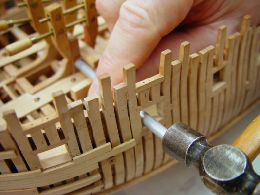
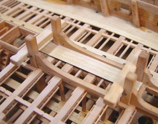
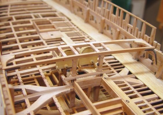
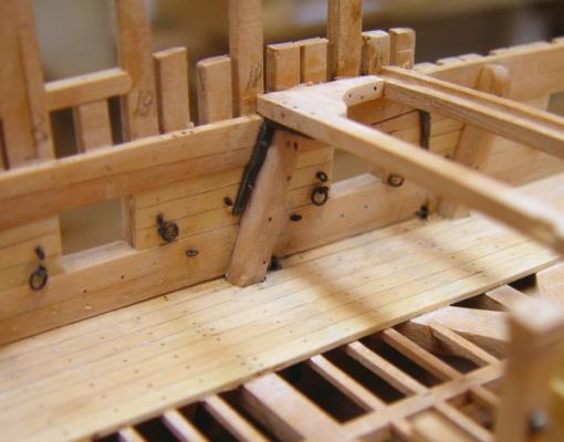
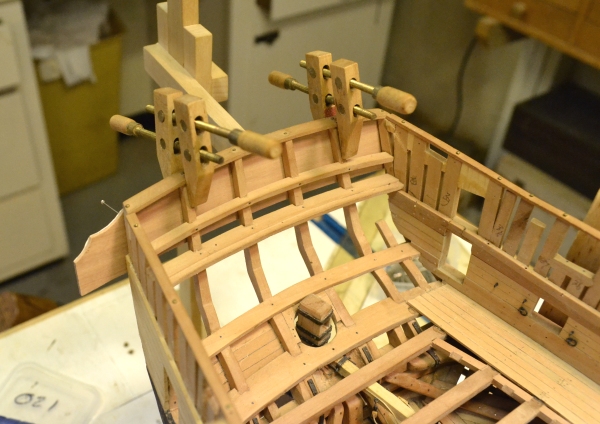
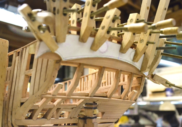
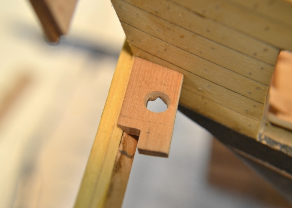
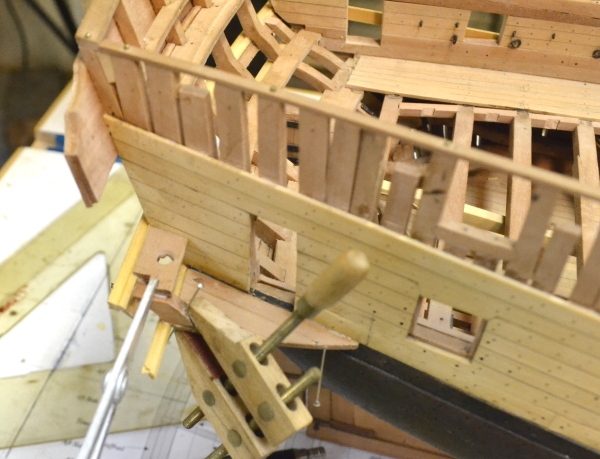
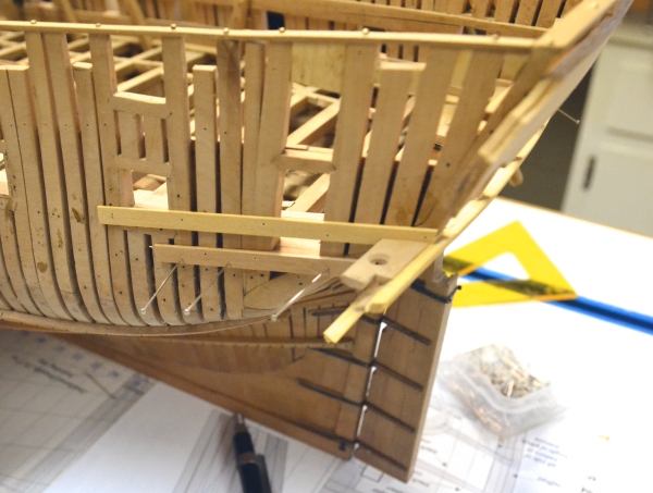
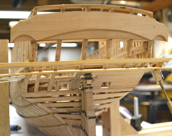
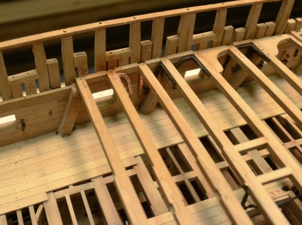
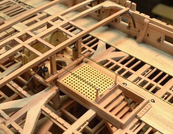
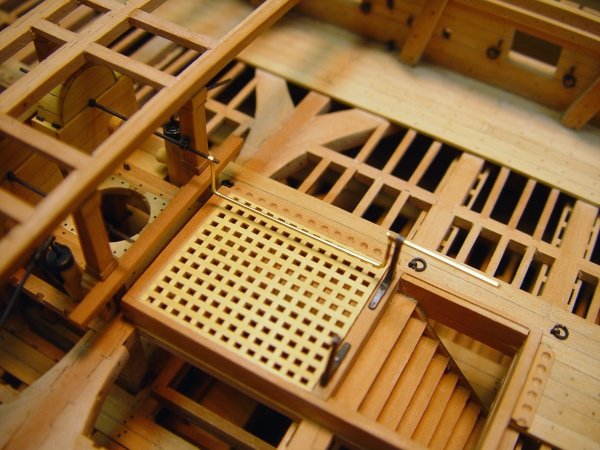
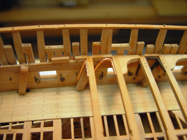
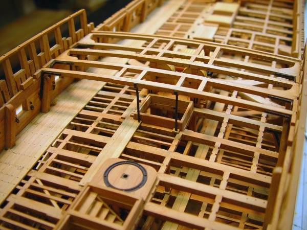
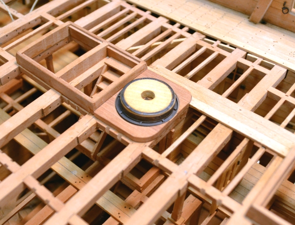
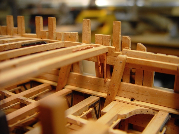
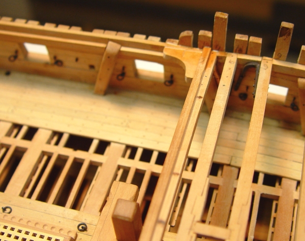
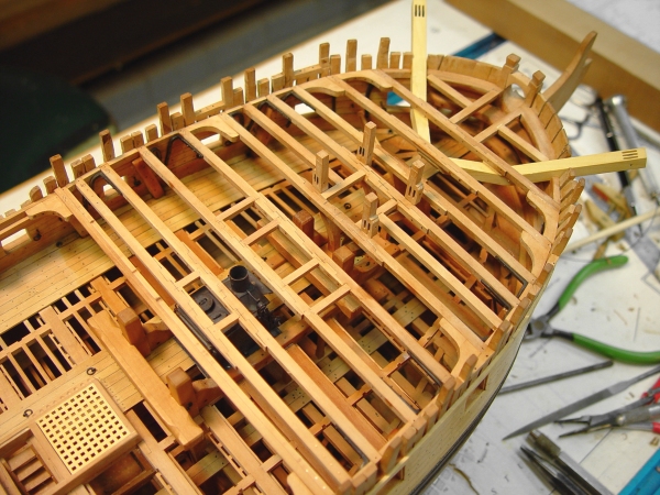
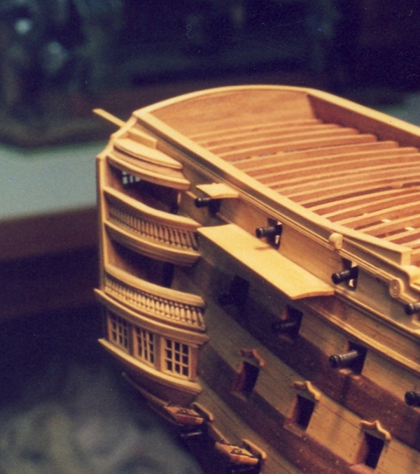
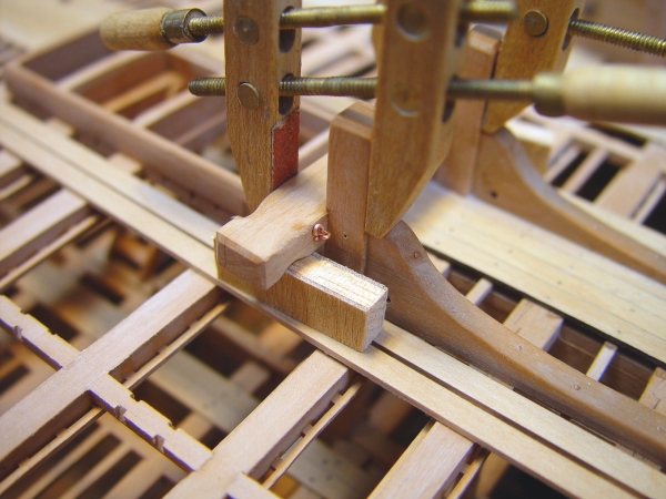
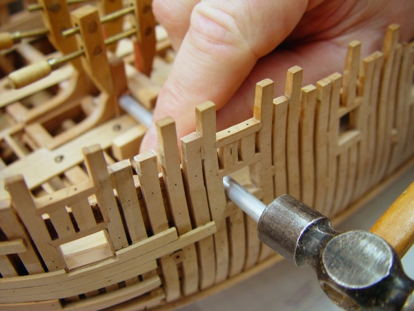
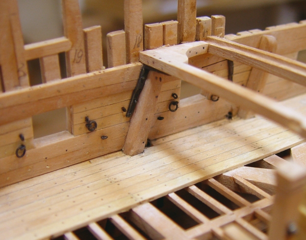
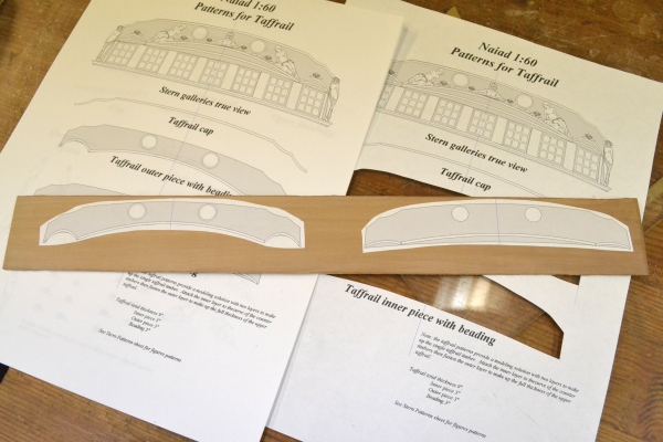
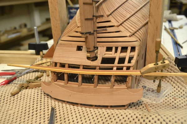
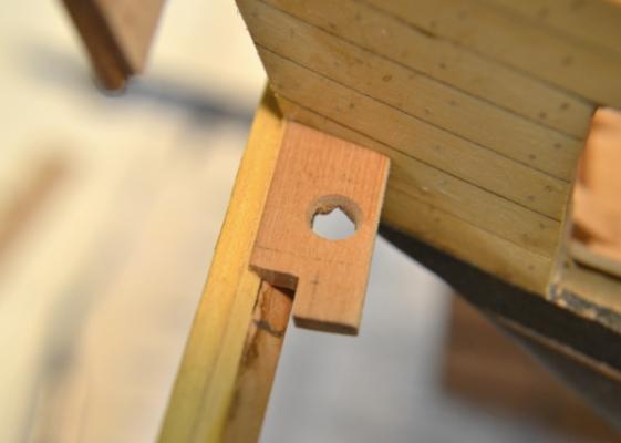
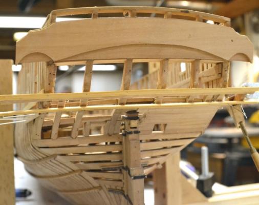
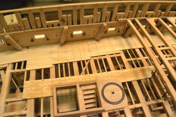
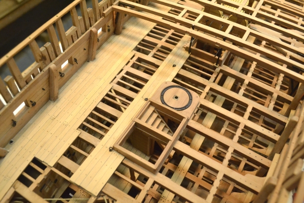
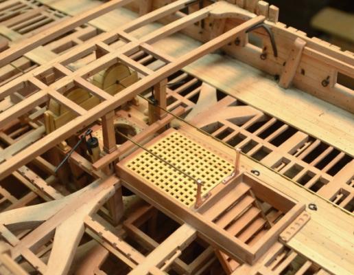
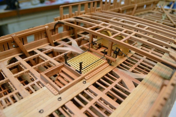
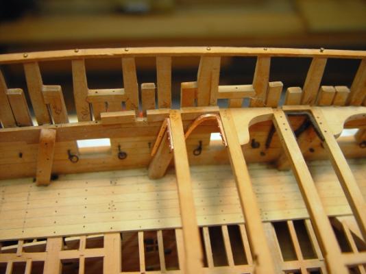
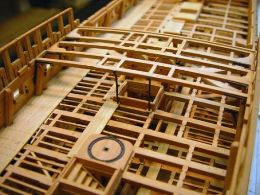
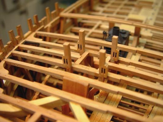
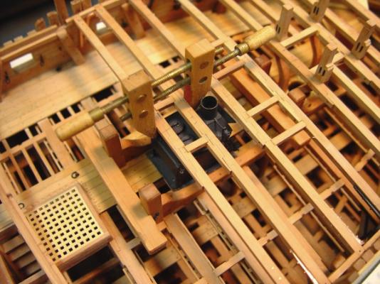
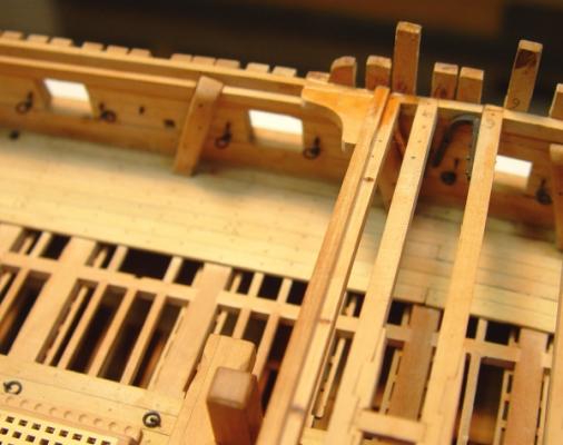
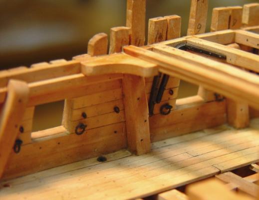
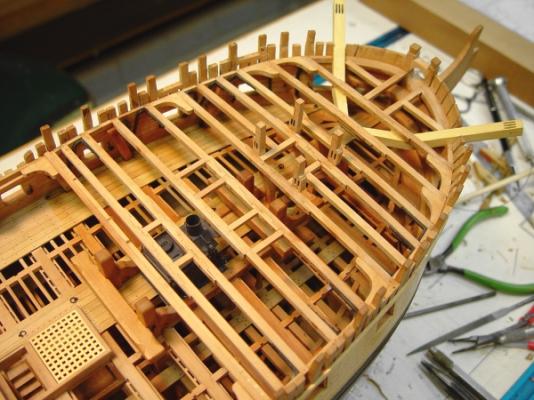
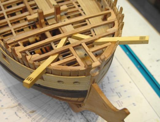
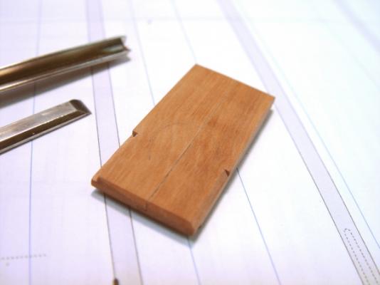
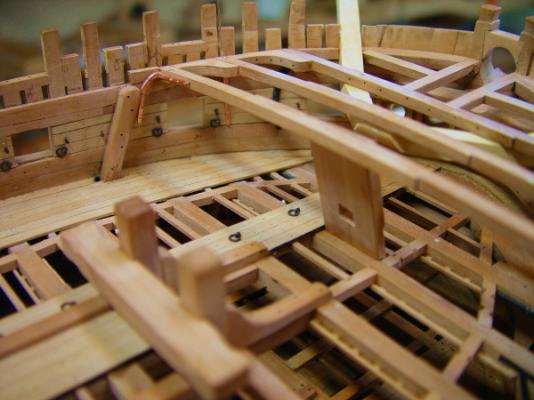
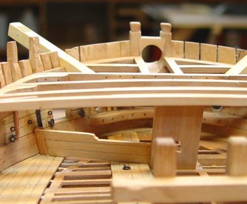
1:60 HMS Naiad 1797 Part 135– Constructing the Stern Galleries 1 Posted 5/30/12 Once I had gotten comfortable with the design for the stern decoration – and once the drawings and patterns were made – I could begin building the structure. The most important member in the stern structure is the taffrail or taferel. It was a large member about nine inches thick with carved figures in relief. Since I am not painting the model I had decided to do all the decoration using European boxwood to contrast with the underlying pear. Also, instead of hollowing out the lower curved areas of the taffrail, I decided to use a laminated construction – two 3” thick sections for the basic member and 3” relief carvings on the surface to make up the 9” overall thickness. The first picture shows the two base pieces ready to be cut out from the 3” thick pear. By this time I had decided to make the two stern chase ports elliptical in shape rather than rectangular, so they are shown on the patterns. The patterns also show the decorative beading that will be added later. In the next picture the inside piece is being clamped and glued to the counter timbers. When the outer piece is similarly glued to the first, the curve will be locked into the lamination, eliminating any significant residual stress. This is being installed in the next picture. With this major member installed, the next step, shown below, was to attach the molded rail at the base of the windows. This is an oddly shaped molding. It rests on the angled break of the touch of the upper counter. I installed a lower counter plank to found it on and then, to avoid the complex trapezoidal shape of a single molded strip, inserted a triangular boxwood section behind the molding so its top surface would be a horizontal ledge outside the window lights. The molding was formed using a scraper cut to the profile. The separation between the rail and the counters was carefully checked across the width. This is the point where careless work on the underlying structure comes home to roost. So far, so good. The next picture shows this planking/molding reinforced with the first of the quarter gallery structural pieces. I made this piece as a combined aft rim/commode. The hole is for the convenience of the captain. Making this in a single wide piece provided increased strength for these first pieces of the quarter gallery structure. The notch in the corner of the seat will form a mortise - when the outer rim pieces is installed - for the bottom of the quarter piece. The seat is pinned to the side with two hidden copper wire bolts. The next picture shows work on the next parts of the quarter gallery. The lower stool – the curved planked pear slab – was glued and pinned to both the top of the black strake at the side and on its aft side to the lower molding. It will be bolted to the side later with long bolts. The lower curved portion of the quarter post was glued in at the same time. This acts as a spacer and assures the proper slant to the lower stool, which should match the molding – and also the deck camber. I expect to make the quarter posts in multiple pieces. These will have figure carvings on their aft/outer sides. The next picture shows the same construction proceeding on the unplanked port side. Small sections of plank are installed to bed the structural members of the gallery. The length of pear planking represents part of the black strake and will bed the lower stool. The piece of box above it will support the forward end of the curved rim piece, which at this stage was merrily boiling away offsite. This picture also shows an overlay sheet placed on top of the original base drawing. The overlay provides an alignment pattern for squaring up the parts of the quarter galleries. This detail was not included on the original base board plan. The last picture is a view from astern, showing rails at the upper and lower counters installed. Obtaining clean tight joint lines on both the upper and lower parts of the rails is involving a lot of flipping of the model upside down and back, so getting this done before installing the fragile quarterdeck detail was a good idea. There is still a long way to go with this work. Ed


-
Thank you for all these comments. Believe me, they are well appreciated. I would love to get all these reposts done and put up some new stuff. Won't be long. Ed
-
HMS Victory by EdT - FINISHED - 1:96 - POB
EdT replied to EdT's topic in - Build logs for subjects built 1751 - 1800
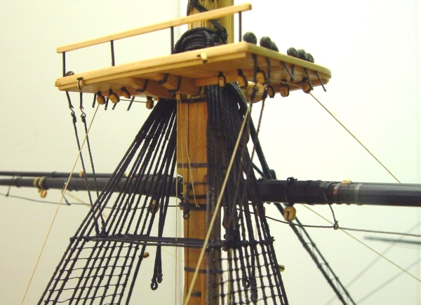
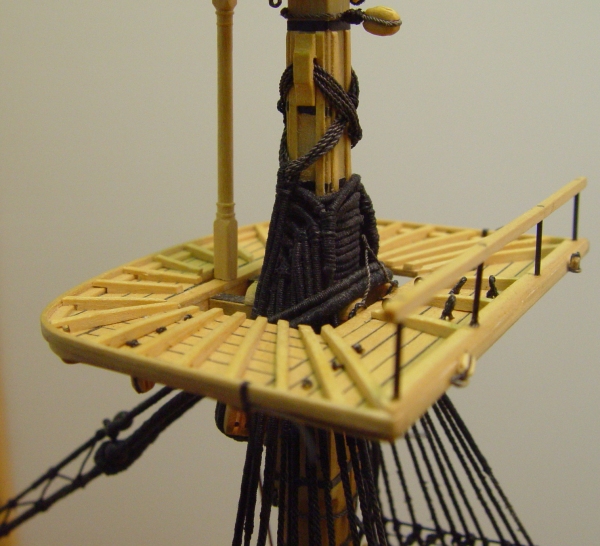
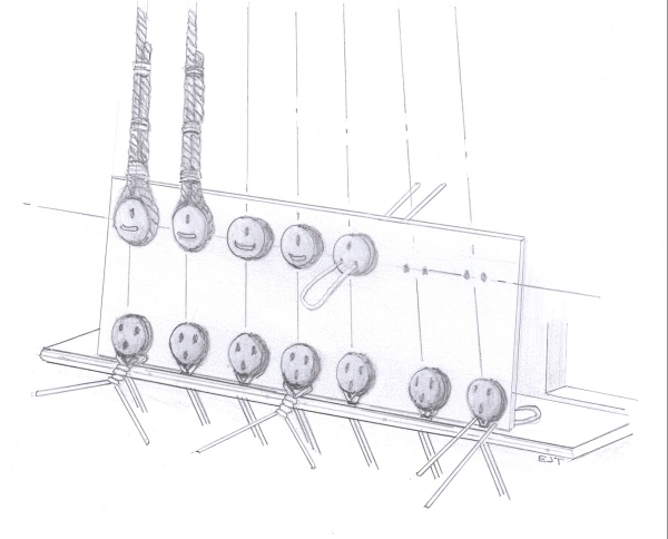
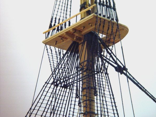
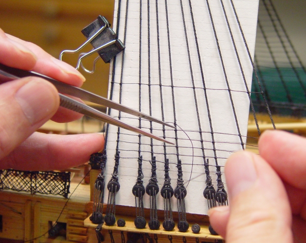
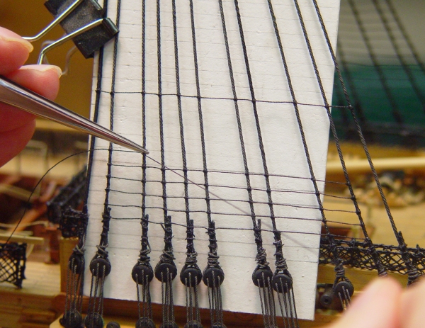
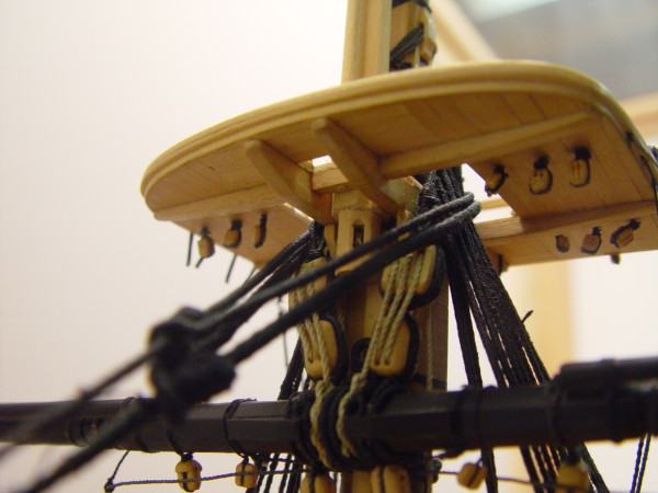
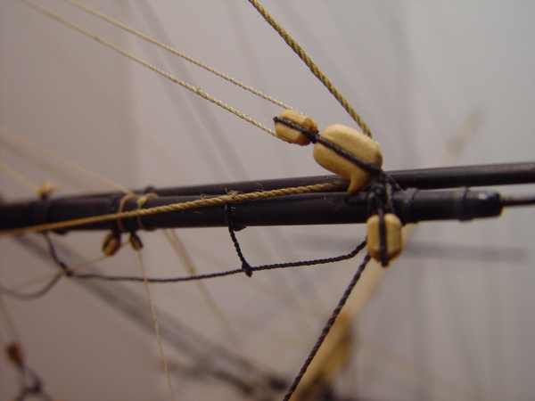
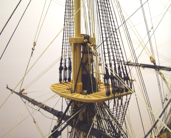
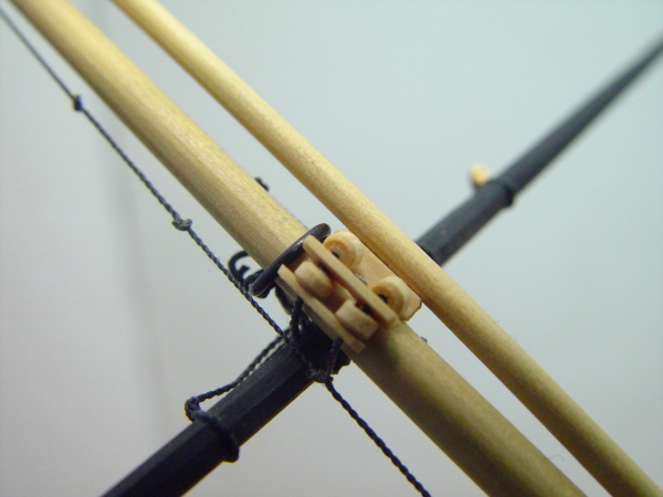
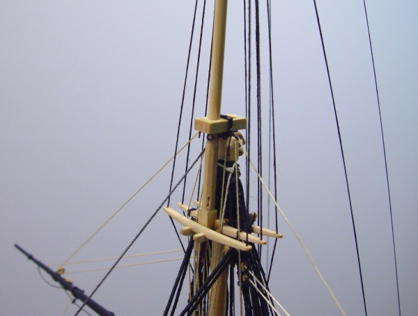
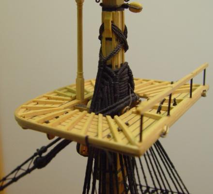
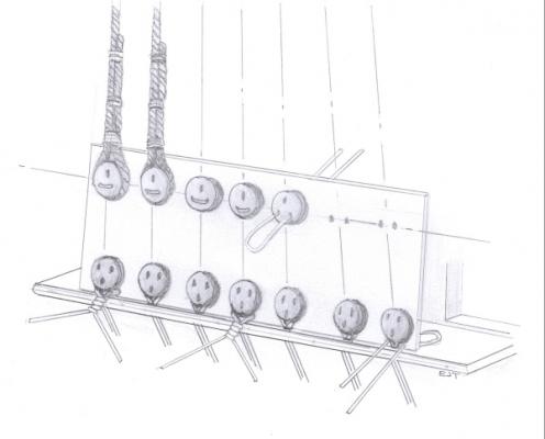
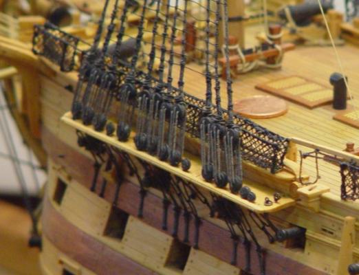
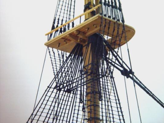
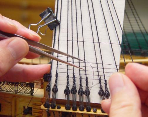
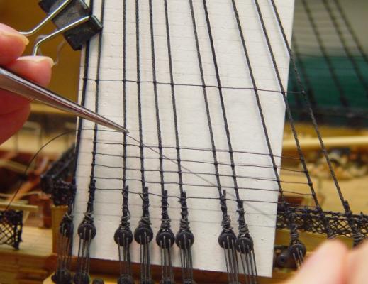
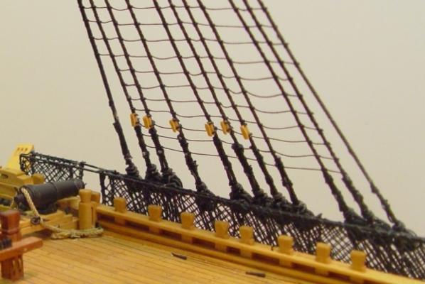
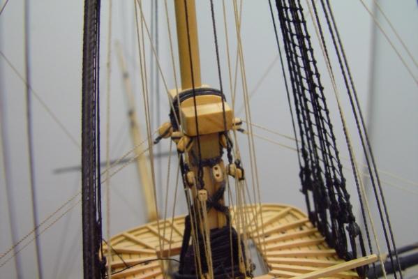
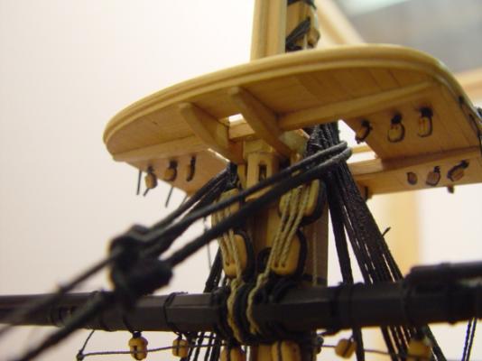
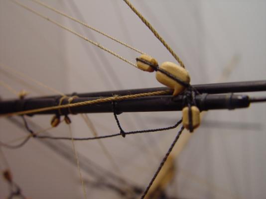
HMS Victory 1:96 Scratchbuild Project Part 16 – Shrouds and Ratlines Shrouds The shrouds for the Victory model were made from multiple strands of linen, twisted up on the ropemaking machine as described earlier, except for the topgallant mast shrouds, which were too small. A heavy black mercerized cotton polyester thread was used for these. All the shrouds are laid up left handed and are four strand if the size could be obtained that way. If not, three strand rope, though not historic, was used. The lower and topmast shrouds are all served over some of their length. The first shroud in each set was served over its whole length, because of the rubbing it took from the yard and other rigging. All these shrouds were served where they wrapped around the masthead. The following picture shows the served portion of shrouds just below the foretop. The next picture shows the served shrouds where they are wrapped around the masthead above the top. Once served, the shrouds go over the masthead in a specific sequence. Shrouds are generally paired in twos and after draping around the masthead are lashed together with a seizing. Some of these lashings can be seen in the above picture. For appearance sake, care has been taken to place these pairs neatly on top of one another and have them oriented so they do not twist over each other as they descend to there proper deadeye. Once all the shrouds were lashed into their positions at the top, the next task was to secure deadeyes to their bottom ends. These needed to be secured at the right length or the deadeyes would not be aligned when the shrouds were pulled tight by their lanyards. The following sketch, shows how this was accomplished on the model. This picture is a composite showing a number of separate steps to attach the shrouds to their deadeyes. First a thin piece of rectangular hardwood about 1/32” thick was cut to be used as a jig for lashing up the shrouds. This was placed on the channel just behind the bottom row of deadeyes, which were installed earlier. Spots were marked at the bottom of this on either side of a few of the deadeyes. The wood was removed and small holes, to take thin copper wire were drilled on these marks. The wood was then returned to the channel and the wire twisted around some of the bottom deadeye chains as shown. A horizontal line was then drawn on the wood at the desired line for the top row of deadeyes. Each shroud was then pulled down to its bottom deadeye and a line drawn at the location where it passed over the horizontal line. The wood was again removed and two holes were drilled at roughly the spacing of deadeye holes on the horizontal line either side of each shroud line. Thin wire was then used to secure each top deadeye to the wood as shown above. The wood was then returned to the channel and secured as before. Having done this, each shroud could be connected to its proper deadeye, assured that it would take its final place along a neat horizontal row with its mates. To secure each shroud it was pulled with moderate tension around the deadeye and clamped back on itself higher up. The short leg of the seized shroud should always be to the right when viewed from the outside. Once tensioned and clamped each shroud was seized with three lashings as shown and the excess clipped off. The shrouds remained attached to the wood after it was removed from the channel to avoid mixing up the shrouds. Starting at the front they were then removed one at a time, first one side then the other, for installation of the lanyards and initial tensioning. All lower and topmast shrouds were installed in this way. The above picture shows the finished fore channel. The various stays that were installed between the lower shrouds were rigged up individually, not part of the above process. Rigging of the lanyards was straightforward. A knot was put in one end of a lanyard rope, to which some beeswax thinned in turpentine had been applied and rubbed off. The other end was wetted with CA and clipped at an angle with scissors to give it a sharp end. This was then threaded from the back through the top left deadeye hole, down through the left front hole on the lower, then from the back through the middle hole in the upper, and so on until all the holes were filled and the lanyard had emerged from the lower right hole at the back. This loose end was then pulled up to put some initial tension on the shroud. This process was then repeated, side to side, front to back, until all the lanyards were installed. Final tension was applied when the forward stays for the mast were installed and tensioned. Each shroud was then tensioned in turn and the end of the lanyard secured in what was a somewhat sloppy, if historical way – as follows. The loose end of lanyard was brought through the small opening between the top deadeye and the first seizing on the shroud. It was then wrapped several times around the shroud and secured to the shroud above these turns with its own seizing. It was very hard to get all these loose ends to look relatively uniform. Here is another picture. Once the lower shrouds were installed, futtock staves made from blackened stiff wire were lashed to each shroud some distance below the top. A number of horizontal catharpins were then lashed to a shroud on either side at this stave. It was important to get uniform initial tension on these catharpins because they are part of the system of lines, which secures the topmast shrouds. If they are too tight the lower shrouds will be pulled inward. If they are too loose tension on the topmast shrouds transferred through the futtock shrouds will pull the lower shrouds outward. The following picture shows how these lines interact with each other. [/size] Here, the lower, futtock and topmast shrouds are all installed, including their ratlines. The horizontal futtock stave across the shrouds on one side and the catharpins lashed across between them can be seen. It can also be seen that the topmast shrouds transfer their tension through their lower deadeye chains (which are not secured to the top platform), down through the futtock shrouds to the catharpins. Also, the forward lower mast stay is putting forward tension on the lower shrouds. All this required a bit of care in tensioning. Ratlines The ratlines are relatively easy to install but it is a repetitive and somewhat tiresome task, especially higher up where arm fatigue can set in. The ratlines are much smaller rope than the shrouds. They are set 13 inches apart. On the prototype they were lashed through eye splices at both ends to the outer shrouds and tied with a clove hitch to each shroud in between. On the model all the shroud connections were done with clove hitches. The process is shown below. First, a card with lines 13 inches apart was mounted directly behind the shrouds as a guide. Then thread was tied to the leftmost shroud with a clove hitch and touched with a small drop of CA. The thread was passed over the front of the next shroud, the end pushed behind the shroud, pulled out from the left of the shroud under itself, pushed behind above itself and then pulled out through its loop with tweezers. I’m sorry if this is complete gibberish, but after a few knots this process became quite mechanical, and so many knots were done that I can recall the exact process easily after three years. Once the knot was loosely formed, the end was pulled to straighten out the ratline between the last shrouds, then gripped at this point tightly with the tweezers and the knot pulled tight. This last step is shown below. After tying off to the last shroud, tension was examined and, if necessary, adjusted by loosening and resetting each knot, before applying a final drop of CA to the last knot. With practice few adjustments were needed. One last task to be done on the fore lower shrouds was to install the tiny boxwood shroud cleats, which were used to belay a number of lines. Space for belaying points was scarce in the on the forecastle and there were many lines to be belayed in this area, hence the use of shroud cleats. These were carved individually and lashed to the shrouds with fine thread. They are shown below. The rigging experience will continue in the next part. Ed Tosti
-
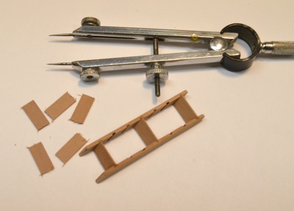
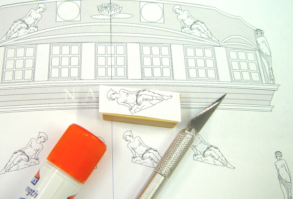
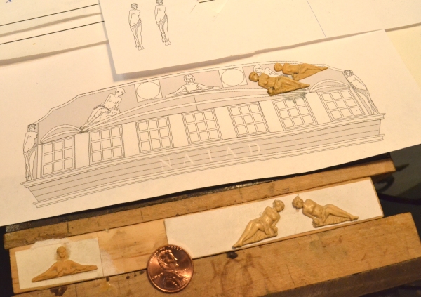
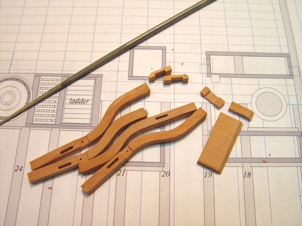
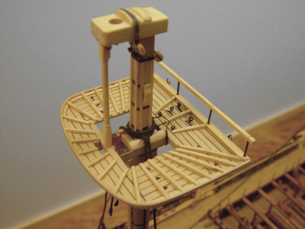
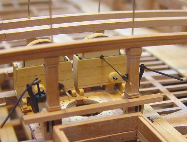
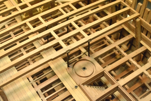
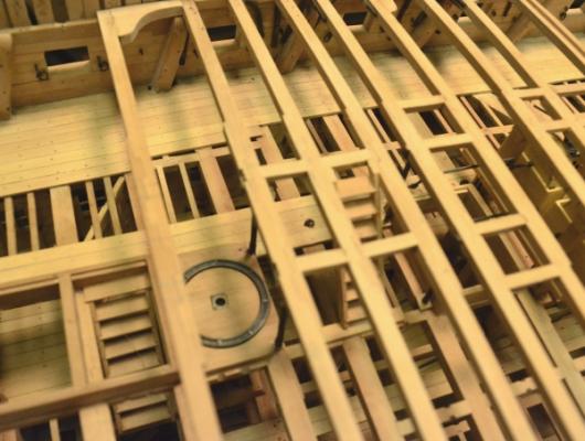
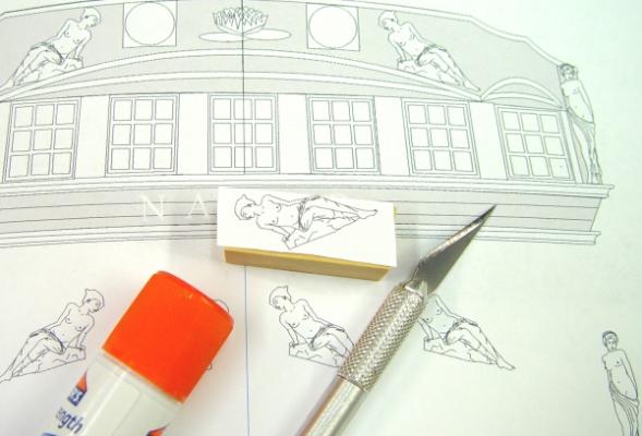
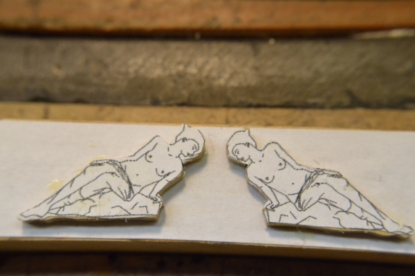
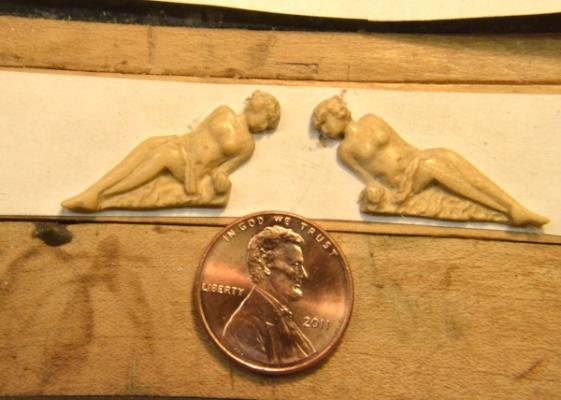
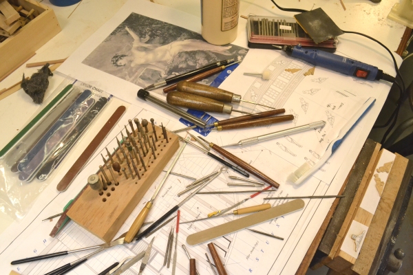
1:60 HMS Naiad 1797 Part 134 – Upper Deck continued/Stern detailing Posted 5/25/12 Again it has been quite a while since the last update, but I can assure you I have been on the job. It has taken some time though, to get visible progress. The beam setting on the quarterdeck has proceeded and this is shown in the first few pictures, but that had to be discontinued because of some construction sequence issues. First, since I am making the capstan in one piece it needs to be installed before the beam aft of it – or it won’t fit. Also, since I want to invert the model to do the detailing of the stern galleries, I did not want to install the capstan or the wheel before doing that – to prevent them from possible damage while the model was upside down. This took me on a long detour to draft the structural detail of the stern and quarter galleries and to design the decoration for them. I will describe this below. The first picture shows the last beam to be installed before moving to the stern work. The two removable iron pillars have been installed under this beam with the bearings for the pump cranks. There is a ladder way forward of the capstan and a picture taken during its fabrication is shown below. The next picture shows the ladder installed. So, on to the work on the stern. I needed to do quite a bit of research to understand and draft the stern structure, especially the quarter galleries, which are not descri9bed well in Steel or in the contracts. Goodwin and White were a big help, but the structure is complex and everything is curved, so it took a while – and a whole new drawing - to get it drafted for building. The modeling of this will be described later. The priority for the next phase will be the stern galleries, including their decoration. Since there is no decoration plan available for Naiad, the model decoration will be speculative. Naiads were mythological fresh water nymphs, so the decoration needs to follow that theme. There will be five figures on the stern galleries, one on each quarter post and three on the taffrail. The evolving arrangement can be seen in the following pictures. The first picture shows a pattern for one of the figures being pasted to a thick block of European boxwood. The basis for this figure is a painting by Henrietta Rae - a 19th century artist specializing in romanticized mythological themes. It depicts a reclining nymph gazing down into a pool from a bank. The quarter piece figures are based on a painting by Arthur Hacker – same period, same subjects. These won’t be needed until later. The central figure in this picture is a water lily, but will likely be changed to the figure shown below – also a nymph. After the outline of the figure was cut out from the block on a scroll saw, the shape was sliced into multiple slabs for the bas-relief carving. The picture below shows two mirror-imaged pieces. Patterns have been applied to both, and both have been glued to a base using wood glue with a layer of paper between so they can be easily removed later. The next picture shows the carving just about complete – if it ever will be – for the three taffail figures. There are couple of practice figures in the picture. They helped define the carving issues and final sizing. The last picture shows a closeup of the two mirrored figures. Carving these two together was my best idea yet. It made it a lot easier to keep them as identical as possible. I won’t go through all the steps here. They are quite small for my eyes and my increasingly unsteady hands so I wanted to make sure I could get something acceptable before putting a stamp on the design. They may be small, but they certainly involved the use of more tools per square inch of wood than any other work I’ve done. The picture below was not posed and more tools were brought to bear after it was taken. This array is a sure sign of someone without a process. By the way, this picture shows the Henrietta Rae picture used – with modifications – as a source. With these carvings done, I feel reasonably comfortable with the design, so the construction of the stern can begin. Ed


-
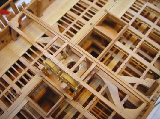
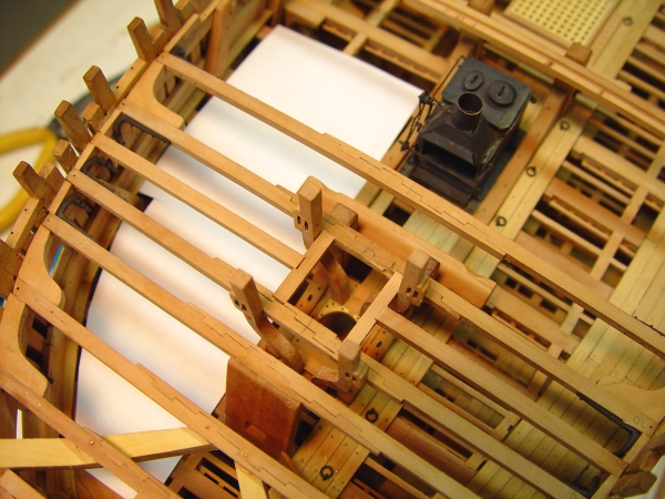
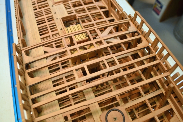
1:60 HMS Naiad 1797 Part 133 – Upper Deck continued Posted 5/7/12 First, thanks to all for your continued generous comments. It has been a lot of small “baby steps” lately. The sequence is complicated by various access problems. The decking in the captain’s cabins cannot be done until the half beams are installed and they must await the rigging of the tiller. That cannot be done until the wheel is mounted, and that in turn awaits the installation of quite a few deck beams. I had to install the decking under all of the beams to that point because once the beams are installed the decks cannot be treenailed – but the area in the captain’s cabins cannot be decked yet. The solution was to end the port side upper deck planking at the forward partition of the captain’s cabin then install the rest later. This unauthentic break in the planks will be covered by the cants that anchor the bottom of the partition and thus not visible. The first picture shows the planking being installed and the break at the ledge just aft of the tiller rope sheaves. The ropes run down from the wheel to these sheaves and thus pass right in front of the partition. In the next picture this planking has been treenailed. There are still some damp spots from washing the treenail glue off and the nail heads have not been leveled off. This is the full extent of the planking to be installed in this area forward of the future partition, except for one or two center planks just forward of the rope sheaves. In the next picture the decking has been filed and sanded flush and smooth. The deck ring bolts for the three gun ports in this picture have also been installed. I have to be sure and remember the shot racks before installing overhead beams. The next picture shows two more beams added. More iron knees of various shapes to avoid the ports and the riders. There is one not visible behind the top rider to the left. The last beam is still loose and the knees for the two ahead of it still have to be bolted – interesting drilling problem. The last picture shows the current state. There will be two iron pillars under the aftermost quarterdeck beam beam in this picture. These will also support bearings for the aft end of the third set of pump cranks. A ladderway interferes with the starboard set of these cranks and would also interfere with the capstan bars, so it must have been removable to allow clearance for these when needed. Cheers all, Ed


-
HMS Victory by EdT - FINISHED - 1:96 - POB
EdT replied to EdT's topic in - Build logs for subjects built 1751 - 1800
Thank, you Grant. The process for making small-scale blocks worked well and turned out a lot in a hurry. It can lead to overly square blocks, so take time in filing the profile to get them properly rounded before parting them off -
Thank you, Ben, for your very overly-generous comment. Book 2 is highly focused on process - as was V1. I believe that is the key to good results for ordinary humans - and believe me, I am in that camp. Thanks again. Ed
-
HMS Victory by EdT - FINISHED - 1:96 - POB
EdT replied to EdT's topic in - Build logs for subjects built 1751 - 1800
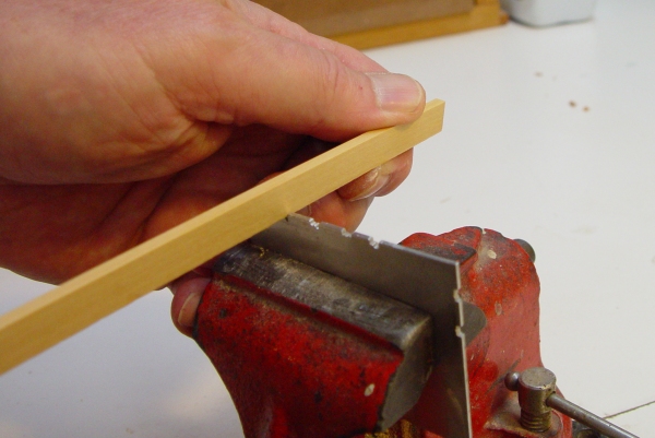
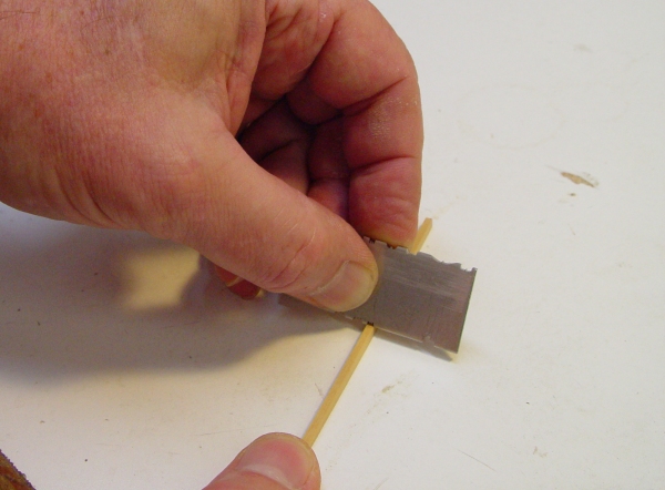
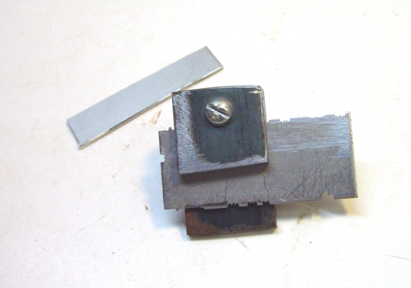
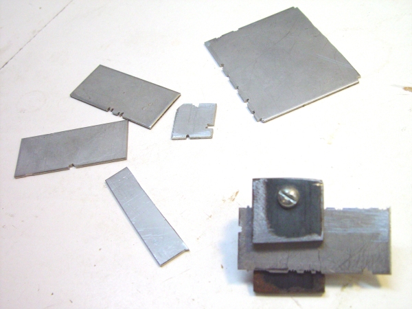
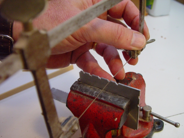
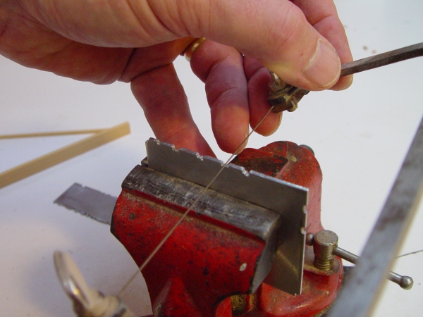
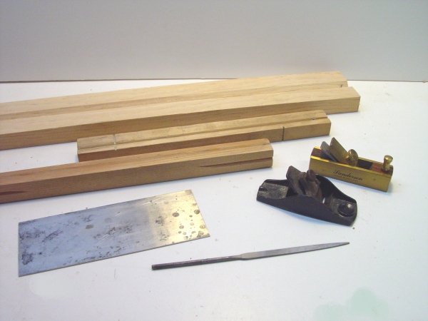
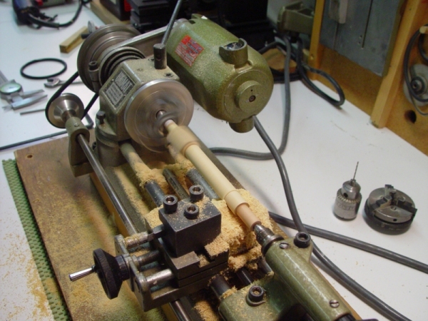
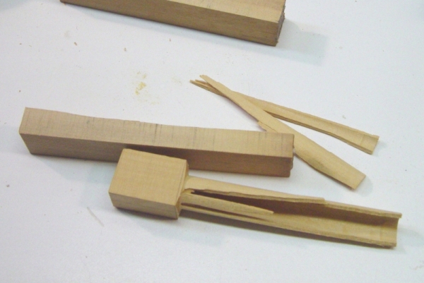
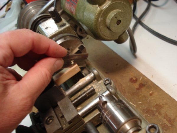
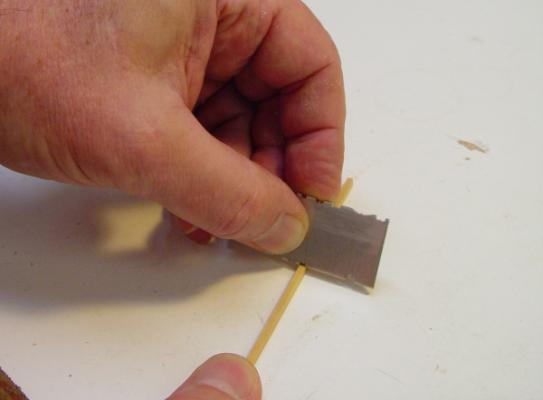
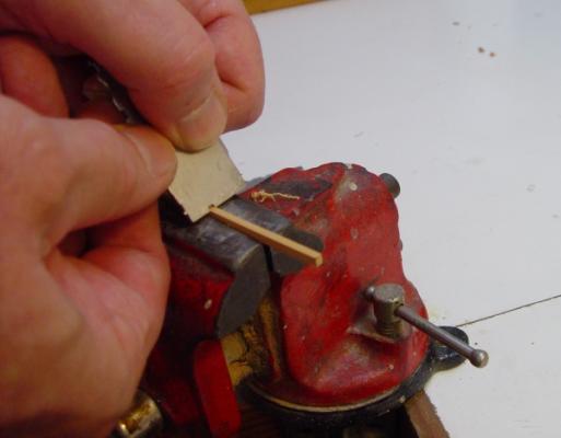
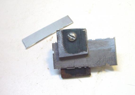
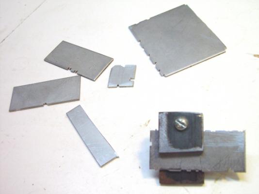
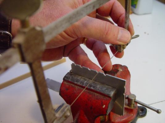
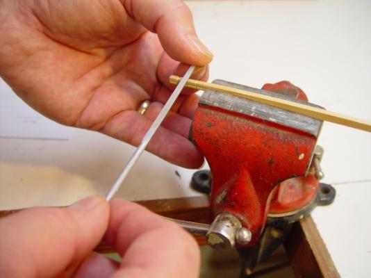
HMS Victory 1:96 Scratchbuild Project Part 15a – Making Shape Scrapers Since putting up the Victory log I’ve had a few requests for more information about the scrapers used to make moldings and block profiles, specifically about how to make them, so in response I am inserting this post into the series. If this does not answer all questions, let me know. Using Shape Scrapers Generally, I have made these as needed, without too much forethought, getting the shapes perfected by trial and error. They are easy to make and produce surprisingly good results. There are a few different ways to use these, depending on what is being shaped. The pictures below illustrate some examples. In all cases multiple light cuts should be used. In this picture a wide strip is being shaped for a molding. When the shaping is complete, the molding will be ripped off on the circular saw. This method assures that the molding will be of uniform thickness if more material is removed at one end or the other. Also, some moldings will not be thick enough to work with the cutter. Its best to keep the stock at almost right angles to the cutter vertically and at a right angle horizontally. More tilt over the cutting edge can be helpful at the start, but by the end of the cutting the wood should be at right angles to get the true shape from the cutter. For shapes where the strip needs to be cut to size first, for example on blocks where all four sides need shaping, the cutter would be used this way – but hopefully more at a vertical right angle to the work. For this application the pattern should not be cut too deep in the plate, but it’s always a good idea to have enough depth to provide entry of the stock before the pattern is reached. The sides should also confine the wood so it cannot get off the track of the pattern. For blocks, the rounded vertical shape of the block can be cut into the scraper, which can be cut deep enough to reach the center of the block body. Uniformly rounded blocks can be made easily this way. Here’s another picture where the right angle rule could use a little more application. If the pieces are short and can be accommodated in a vise, this approach works well. Here the sheave groove for a single block is being cut. Note the rounded sides on the cutter. Simple grooves of very small size can be cut with scrapers where saw blades or files are too big. Using the clamping device in this picture as a fence allows one cutter to be used for several different groove locations by varying the distance from the cutter. The clamp is made from two pieces of 1/8” carbon steel, rounded off on their edges which a file, then drilled and tapped to take a tightening screw. This is pretty much the collection used on Victory. After scraping, avoid using sandpaper on the shapes. It will obscure the detail. A buffing with very fine steel wool or fine grade non-metallic 3M abrasive pads, will polish up the shape nicely. Making the Cutters My cutters are made from scrap pieces of 16 gauge stainless steel, only because I happened to have some. Most cutters have limited use, so they could be made from plain carbon steel or even hard brass plate. If you are going to use hardened steel plate, say, for example a carbon steel saw blade, then that will need to be stress relieved to make it soft enough to cut with a saw or file. To stress relieve hardened steel, heat the piece with a torch until it is “cherry” red, then allow it to air cool. It can then be worked with files and saws. Hardened steel can be worked as is with abrasive wheels in a motor tool, but this might limit the profiles that can be made. I would recommend avoiding this by finding a piece of roughly, 16 gauge (1/16” or 2mm) plain carbon steel scrap. For moldings, where the final shape can be sliced off after shaping, I would start by cutting a square slot the width of the molding, then lightly rounding the side edges of this, so the wood will slide within the sides without scraping. The pattern can then be cut on the bottom face of the slot. The pattern should have crisp edges where it will be scraping away the wood. When cutting the pattern, cut at a right angle to the plate. An angled knife edge is not needed, just a sharp unrounded corner. The pictures below show a cutter being shaped using just a jeweler’s saw. Very fine patterns can be cut with this tool tilting the blade to one side or the other. For fine detail this is the tool of choice. Use the jeweler’s saw to cut on the pull stroke. Blades in many sizes down to the very finest are inexpensive and easily replaced when they break. Get them from a jeweler’s supplier – or even Amazon.com. A jeweler’s saw frame can be had for $20, or so, and is a good investment – for this and many other modeling tasks. Where the shape requires smooth curves the pattern can be dressed up with very small files. Just be careful not to round off the cutting edges. Small files in various shapes are available from suppliers of modeler’s tools. Sharp edged files for sharpening Japanese style saws are very good for narrow slots. I usually try to avoid using files on both metal and wood because they can leave metallic smudge on the wood. Separating these uses is not always easy. I still prefer the jeweler’s saw for most of the work. The best way to know if you’ve got the right shape is by trial and error. Careful marking out with a scriber is a good way to start, but I have found that sooner or later testing the width or the pattern with a piece of the wood stock will need to be done. Ed Tosti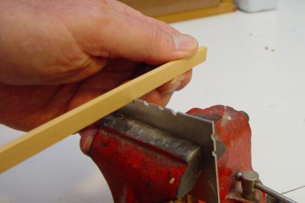

-
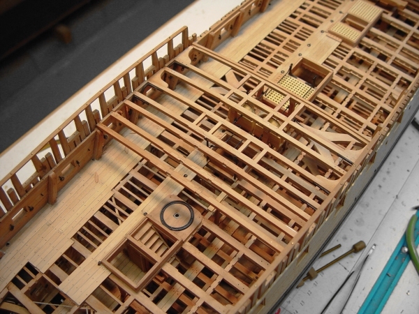
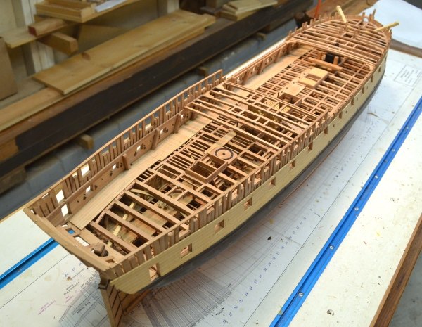
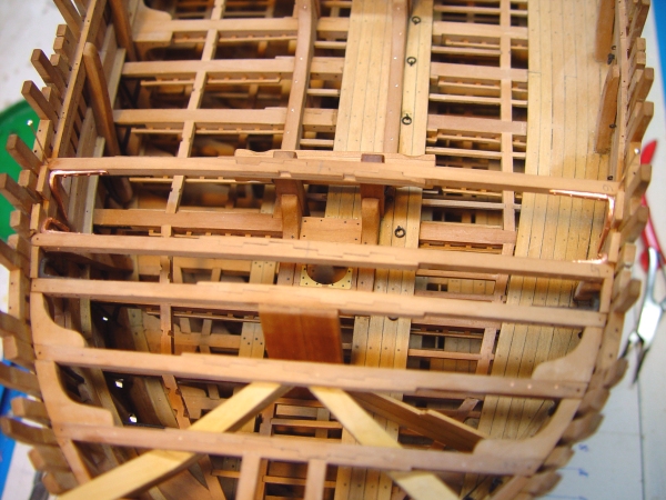
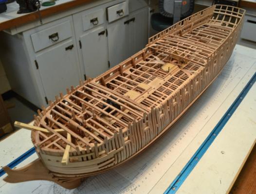
1:60 HMS Naiad 1797 Part 132 – Pump Cranks Posted 5/1/12 A lot of things have been getting between me and the shipyard in the past two weeks, but some progress has been made. In the picture below two self-standing stanchions have been fabricated from sheet copper and installed at the forward end of the main hatch. Long straight rods the same diameter as the final crankshafts were used to maintain a straight line through all the bearings. In the next picture the stanchions have been blackened and the fabricated crank parts are being test fit. The collars at the ends of the crank were made by drilling a hole into the side of a piece of tubing, which had been filed square on the outside. The ends of the cranks were then silver soldered into these holes. The tubing segment was then re-bored to fit the shaft material. Below, both cranks over the hatch have been blackened and installed. This picture shows a few additional beams installed aft of the pump area. The next picture shows two of the iron knees on these beams before bolting and blackening. These beams needed to be installed concurrently with the iron stanchions that support them and also support bearings for the after end of the pump cranks. Two of these stanchions are shown in the next picture. There will be two more of these under the beam that will support the forward end of the quarterdeck capstan step. These were removable to clear the capstan bars when in use on the upper deck capstan head. The next picture shows the extant of the quarterdeck beams installed so far. Finally, I realized that almost all the pictures for some time have been interior close ups, so I included two pictures showing the full model at this stage. This was a rare moment when the workspace was clear of the usual litter. This shows the partially planked starboard side. The last picture shows the port side, which will be left unplanked. If the lighting and coloring in these pictures seem a bit inconsistent, it is because I am switching over to a new camera and undergoing some startup learning. Cheers, Ed


-
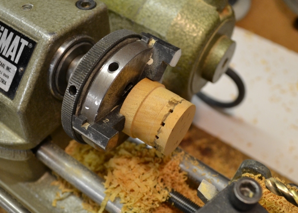
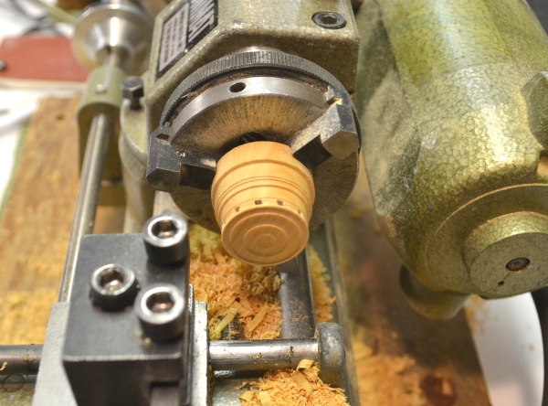
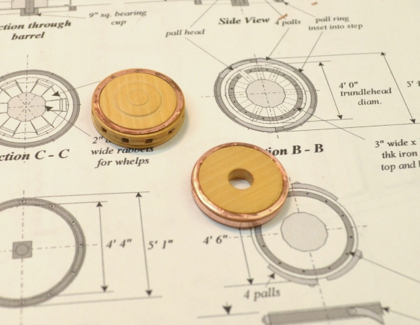
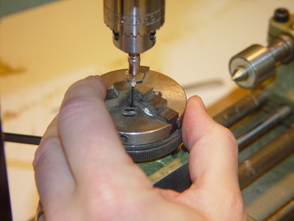
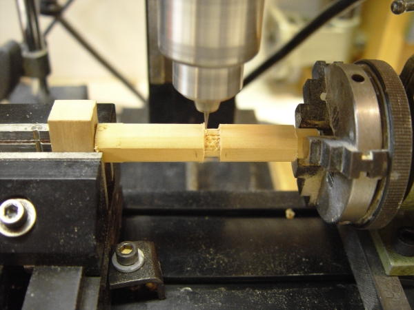
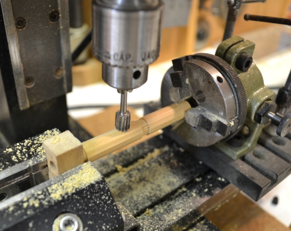
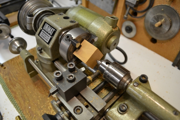
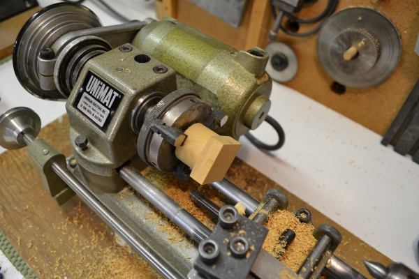
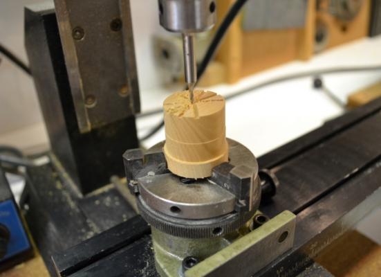
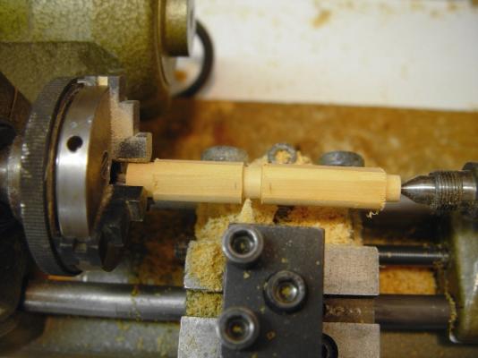
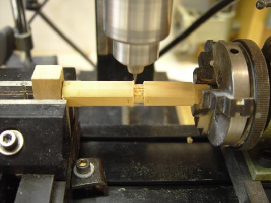
1:60 HMS Naiad 1797 Part 131 – Capstan 2 Posted 4/17/12 Continuing the work on the capstan, I decided to make the three heads next – the drumhead at the top, the trundle head on the upper deck and the pall head at the base, just above the lower step. In the first picture a block of European Boxwood has been set up in the independent 4-jaw chuck. The piece is rough centered for this by adjusting each of the four jaws until the four corners of the square work piece just touch the bit when rotated. A dead center is being used in the tailstock to make a center mark on the piece. This will be used for measurements and any boring. The wood block is a roughly ¾” cube and is set up with the grain direction perpendicular to the lathe centerline. In the next picture the square has been turned to a round and the face has been squared off. It was then flipped end for end and re-chucked – this time in the 3-jaw centering chuck. This chuck switch is made so the piece can be removed and still be on center when re-chucked – and also because my indexing head can take the 3-jaw chuck. The square end was then turned to a round, center-marked and the end faced off square. Sorry if I am belaboring this, but there were some questions last time on centering, so I hope this is useful. This piece will become the drumhead. In the next picture the piece with the 3-jaw chuck has been set up in the milling machine on the 48-tooth indexing head. The 12 square holes for the arms are being cut to half depth. The process is the same as was used for the steering wheel so I won’t repeat all the steps. After this the end that will become the top was parted off in the lathe. The remaining piece was then returned to the mill and similar cuts made. These scored faces were then glued together with their grain crossed for final turning as shown in the next picture. Before joining the two parts - the chucked lower part only - was bored on center. This hole will either be converted to a square mortise or simply mounted on a turned stub on the top of the barrel. In the next picture the drumhead turning is just about finished. There are iron reinforcing rings let into the top and bottom just inside the perimeter. A circular score has been cut for the top ring. The turning has been polished with steel wool. The head will now be parted off at its final thickness – 11”. The next picture shows the drumhead with its iron (copper) ring set in the top score. The picture also shows the pall head, which was a lot simpler to make– one disk only. It is reinforced with a ring like the one on the drumhead, but also an iron band around the outside. The top and bottom rings were photo-etched. The band on the outside of the pall ring is just a strip. At this stage the rings on the pall head have been glued on with medium CA and also bolted with 12 small diameter (22 gauge) stretched copper wire nails each. The last picture shows the pall head placed over the upper deck step. It fits just inside the pall ring. It still needs its four palls to be made and fitted. In this picture the ironwork on the pall head has been blackened. In preparation for this the copper was polished and the assembly cleaned thoroughly with acetone and a Q-tip to remove any traces of excess CA. The copper was then brushed with liver of sulfur and washed with water. Although there is a hole in this piece I have not decided how these will be attached to the barrel yet. The trundlehead will have to be cut to fit over the 12-sided barrel, but the other two heads could simply be fit over a turned end, since the joints will not show. Ed


-
HMS Victory by EdT - FINISHED - 1:96 - POB
EdT replied to EdT's topic in - Build logs for subjects built 1751 - 1800
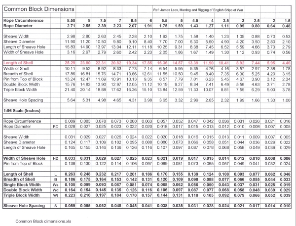
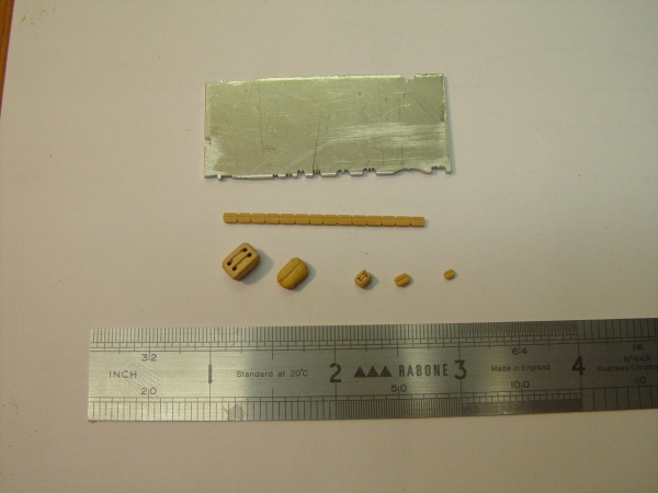
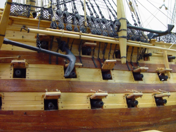
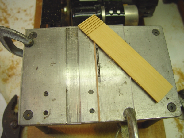
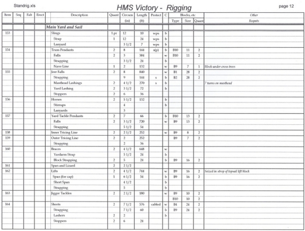
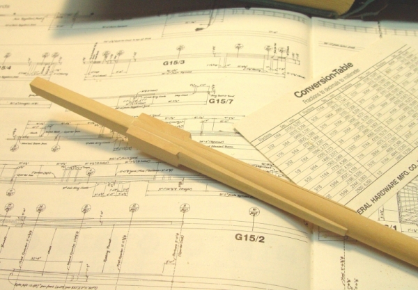
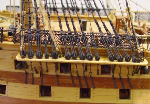
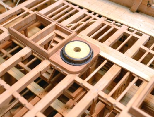
HMS Victory 1:96 Scratchbuild Project Part 15 – Deadeyes and Blocks Deadeyes Deadeyes were used to restrain and to put tension on various standing rigging lines. The larger deadeyes in the above picture, on the fore channel, are anchoring lower shrouds and the smaller ones are securing topmast backstays. With three holes each, a pair of deadeyes takes the strain on the shroud over six lengths of lanyard. Discounting friction, this means that pulling on the lanyard with a force of 100 pounds, puts 600 pounds of tension in the shroud. Lower shrouds were tensioned by a block and tackle attached to the burton pendants, suspended from the masthead. The tension on the shrouds thus got the benefit of the additional leverage from that tackle as well. Deadeyes are simple devices, round blocks of wood grooved around their circumference. This groove was sized to take, for example a shroud on the top deadeye, and an iron ring – a deadeye chain link – on the bottom one. Each deadeye also has three lanyard holes. These three were slightly off vertical center and the holes had their edges relieved to reduce friction and wear on the lanyard by providing a rounded surface. On the model, these last two features were omitted. Model deadeyes were made from boxwood. First, dowels were turned to the deadeye diameter in the lathe. After cutting grooves with a rounded tool, they were parted off using a shaped parting tool that would give them their rounded edges. They were then set up in a three jaw chuck mounted on an indexing head so that holes could be drilled precisely 120 degrees apart in the deadeye face. A picture of this process is shown below. In this step the deadeye is setup off center of the drill by the radius of the hole location. The first hole is drilled. Then the indexing head is rotated by a number of clicks equaling 120 degrees and the next hole drilled. This is repeated and the deadeye removed from the chuck. The indexing head makes this process easy because it can be used for all deadeye sizes. Deadeyes down to 7 inch diameter, a bit more than 1/16 inch, were drilled this way – albeit with some failures at this small size. This approach resulted in very uniform deadeye holes, which is an advantage because on the ship they are all lined up next to each other for comparison. Obviously a rotary index head could also be used. In the absence of either of these rather expensive tools, a jig could be made for each size with alignment holes for the drilling. Longridge describes such a device. Once drilled, the deadeyes were touched up with sandpaper then dropped into a jar containing black acrylic ink. After removal from the jar they were allowed to dry thoroughly, then immersed in diluted tung oil for 24 hours. When removed they were rubbed dry, their holes cleared of any oil, and allowed to dry for a couple days. They were then treated with beeswax diluted in turpentine to make the lanyards slide more easily. Dead eye chains were made from elongated loops of brass wire, silver soldered together, shaped to fit their deadeyes and then assembled into chains of the right length. These assemblies were then attached to chain plates nailed through predrilled holes the middle wale with blackened brass nails to represent bolts. Chains vary in length, getting longer toward the aft end of the channel due to the increasing rake of the shrouds. If the middle links in these three link chains are made by wrapping wire around a strip of wood, then cutting off and soldering as described in an earlier part, tapering the wood strip will yield loops of uniformly increasing size. From the resulting collection of loops, correct lengths can be selected. Deadeyes in the tops were done the same way, but their chain loops were fastened to the futtock shrouds by small hooks formed from brass wire. Blocks Victory’s collection of blocks varies from 26” triple jeer blocks down to single 5” blocks for ensign halyards, with almost every size in between. The rigging schedule discussed earlier was valuable in making sure the correct blocks were selected for each line and for totaling up the numbers required. The following table was helpful in making these blocks proportionally and dimensionally correct. Its just a spreadsheet with a lot of measurement conversions based on information from Lee’s, The Masting and Rigging of English Ships of War 1625-1860, in which he lists proportions of common blocks based on rope circumference. This table just multiplies out all those proportions and reduces them to scale dimensions, which can be used to size the model block. So, if for example the rigging schedule calls for a fifteen inch, double block, the entry with the nearest shell length (in red) is 14.87 inches. At the bottom this gives block dimensions of .155 inch length, .109inch breadth, .097 inch width, a sheave hole diameter of .019 inch and a hole spacing of .035 inch. Blocks of this size would then be made to roughly these dimensions. Although it may seem so, this table is not about precise sizes, only about reasonably correct proportions. There are of course, some “uncommon” blocks. Clue line blocks have broad upper shoulders to protect against chafing by the sails; topsail sheet blocks have a shoulder at the bottom to prevent fouling of the lift against the yard; lower single blocks on topsail yard tyes are long but of narrow width; to name a few. Although it is possible to put sheaves in the larger blocks at this scale, I decided not to do this, since the sheaves would be mostly hidden by rope. So, all blocks are merely drilled to simulate sheaves. To make the blocks, strips of boxwood were ripped to the width and breadth dimensions. Grooves for the sheave holes and for the groove on the sides to hold the strap were scored down the strip with formed scraper cutters. A picture of one of these cutters with some blocks and a finished strip is shone below. The picture below shows some leftover unused strips at different stages. In this picture the top strip has been scored on all four sides. The next one down has had spacing holes drilled along the side face. These are spaced using the calibrated wheel on the milling machine cross feed. The purpose of these holes is to accurately define the length of the block and to provide a small groove at the top and bottom to help seat the strap. The strip is then rotated in the machine and the top and bottom rope holes are drilled in the grooves at the correct spacing, again using the cross feed wheel calibrations. The fourth strip shows some of these holes on a strip that has also had some additional work. The last strip shows some of the first shaping. This is done with files as shown below. First, small v-grooves are cut around the circumference of the strip with a triangular file at the location of the side holes to define the top and bottom of the block. The rounded shape is then filed on each block, which is then parted off with a fine saw and given some final sanding to remove burrs and polish the block. No further finish was applied to these. After this, the blocks were strung up on wire and placed in labeled cardstock holders as shown below. Here are a few pictures showing some of the different blocks on the model. This picture shows blocks at the end of a lower yard. The large topsail sheet block has the shoulder described earlier. It is in a strap with a loop at the bottom to go over the yard end and has a smaller block for the yard lift seized in the same strap. The brace block has not yet been rigged. It is connected through two loops so it rotate freely. Most of the blocks were attached before the yards were installed. Several pairs of blocks are strapped over the bolster at the top of the lower masts. The yard lifts are connected to an eye in the strap of a block, run out the yardarm then come back up through the block and run down to the deck. Another similar pair guides rigging from above through “lubbers hole” in the maintop down to the deck. A lot of smaller rigging for the upper yards is rigged through blocks in the top. The larger unrigged block strapped to the masthead will soon take the main topmast stay. The largest blocks on the ship are the jeer blocks for raising and lowering the fore and main lower yards. They are 26” long, a double and a triple. The upper jeer blocks are suspended by double straps, which are secured to the masthead by several turns of lashing. The lower ones have double straps looped around the yard inside the sling cleats. All these large straps are served. At the bottom of the yard, just outside the sling cleats is a clue line block with shouldered sides described earlier. A dozen small blocks are suspended under the top to guide buntlines, leechlines and spritsail braces from forward to the aft side of the mast and down to the bitts forward of the waist. The next part will continue the discussion of rigging. Ed Tosti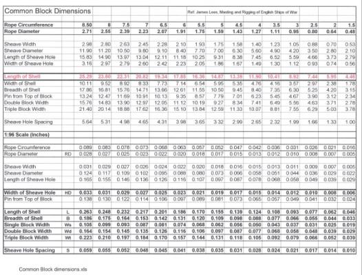


-
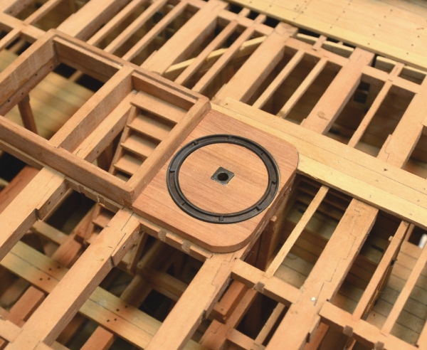
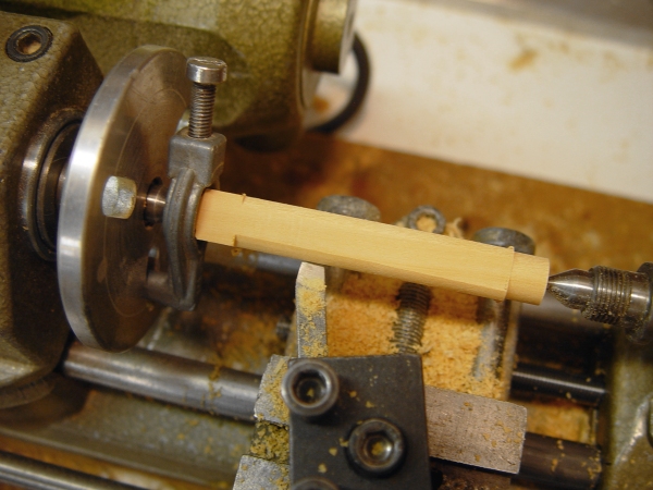
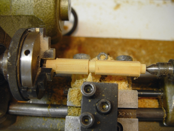
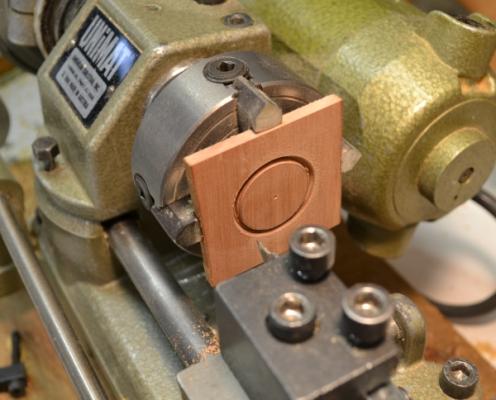
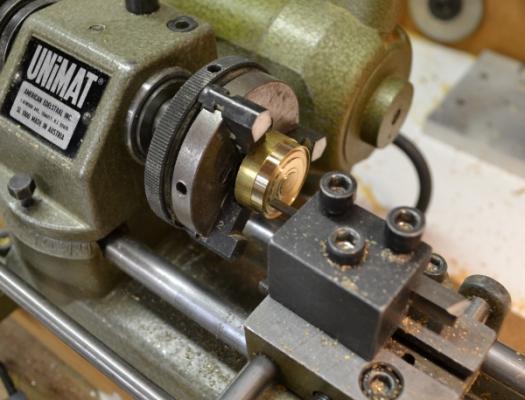
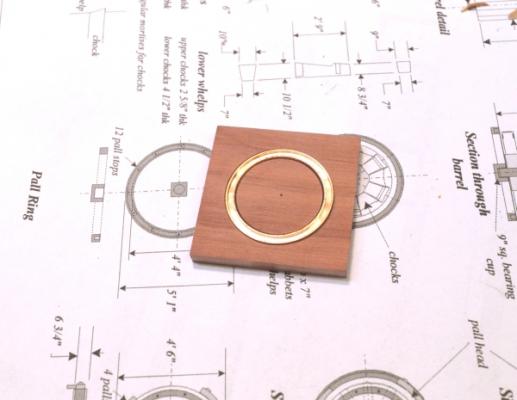
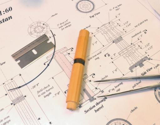
1:60 HMS Naiad 1797 Part 130 – Capstan 1 Posted 4/15/12 Although it has been a couple of weeks since the last post, work continues. As the work on the quarterdeck has been moving aft, the capstan has been looming as a major project. I spent a good bit of time examining drawings and the scantlings and then doing the 1:60 drawing for Naiad. The first step was to replace my previously installed upper deck step, which did not have a pall ring. The first picture shows the machining of the inset to take the ring. The inset was machined first, then the step sized around it. This was done concurrently with the machining of the ring itself, shown below, to assure a good fit. The machined ring is shown below fitted into the step. Eight palls were then silver soldered into the ring. The final ring is shown below after blackening, in the step, in position on the upper deck. The bearing cup, removed from the first step has been centered and installed in the new one. Concurrently with this work, the barrel of the capstan was begun. In the first picture a piece of European Boxwood is being turned between centers. With the piece between centers the end to the right of the picture was turned to a diameter of 24”. This is the width between flats of the 12-sided polygon shape. It will be used to set the height of the tool to machine the flats. The middle section was left larger. In the next picture the piece has been flipped and the round end held in the three-jaw chuck with the other end held on center. The tailstock end was turned to an actual 5/16” diameter to fit into a makeshift centering device shown below. In the picture the round bearing area at the level of the quarterdeck step is being turned to a 22” diameter. The next picture shows the piece, still held in the 3-jaw chuck, having the slots for the iron bearing strips machined with a very small spherical cutter. For this and the next step, the 3-jaw chuck has been moved to the milling machine set up with an indexing head with 48 teeth without removing the work piece. The opposite end is set up and held on center by the improvised piece to the left. Two increments between passes yielded slots for 24 strips. In the next picture the 12-sided shaped is being cut. As mentioned above, the height of the cutter is set at the diameter previously turned, now at the chuck end. There are four increments between each pass in this step, yielding the twelve-sided shape. The next picture shows the barrel with the 24 bearing strips installed. These were made from the black monofilament, shaved off flat at the diameter. They may be slightly oversize, but I could manage nothing smaller. I’m hoping to show some of this bearing detail on the finished model. The barrel is still over length at this stage Ed


-
1:60 HMS Naiad 1797 Part 129 – Y-Bitts, Forecastle Beams Posted 4/3/12 The fore jeer and topsail sheet bitts surround the foremast on the forecastle. On the Naiad draft, the jeer bitts are indicated as Y-bitts, but it is unclear if this specification is meant to apply to both sets. I decided to take this interpretation and make both sets as Y-bitts. The picture below shows the parts after fit-up and before assembly. The sheave caps on the sides were sliced off of the larger piece to the right. In this piece the sheave opening was milled and the decorative mold at the top filed by hand before slicing off the pieces. In the next picture the bitts have been installed. The white paper on the upper deck is my solution to minimize small parts dropping into the lower depths. This can be a real problem because tweezers are no longer a feasible extraction method if the pieces reach the bottom. I have had to unbolt the model once or twice to shake out parts that were too valuable to abandon until the next major clean out. The next picture shows the installation from forward. This picture shows that in my concentrating on these details I had forgotten to install bolts in the made beams and in the mast step. These were soon added. This is easier to do before installing the beams – obviously. In the next picture the beams over the stove are being installed. In this picture the carlings supporting the vent grating over the boiler lids are being clamped for gluing. I wonder if the barrels of salt meat were dumped into the boilers through this opening or from under the deck? There is not much space for the latter. There is also a grated opening framed over the range area at the front of the stove and the stack will come up through an opening in the deck that will be covered by a metal plate. This latter grated opening is flanked by two openings for rigging – but I am not sure which lines require these openings. The next picture shows some support detail for the beams at the aft end of the forecastle. There must have been a lot of onsite improvisation in configuring all these iron knees to avoid the ports, port ironwork, riders and each other. In this case, another iron knee supporting the breast beam – not yet installed – will fit between these knees and the rider. The next picture is a view of the installed breast beam. This is an interesting beam. It has a wood lodging knee on the aft side – the appropriate orientation for beams in the fore-body. It has an iron hanging knee that can be seen just aft of the rider. The beam has a rabbet on top to butt the forecastle planking and a decorative molding on its aft face. Because of the rabbet and the molding, this beam and its quarterdeck counterpart were made in one piece. The next picture shows a close up of the end of this beam. The forecastle and gangway planking will butt against the upper portion of the beam with the forecastle planks resting on the top rabbet and the gangway planks resting on the lodging knee. The rounded molded face at the top of the beam will be cut back to take the ends of the gangway planks. The hanging knee for the beam is hidden behind the rider in this picture. The next picture shows the forecastle framing completed and ready for coamings, head ledges and planking. This picture also shows that wax finish has been applied to the upper deck and between-deck structures below the forecastle. Cheers, Ed


-
HMS Victory by EdT - FINISHED - 1:96 - POB
EdT replied to EdT's topic in - Build logs for subjects built 1751 - 1800
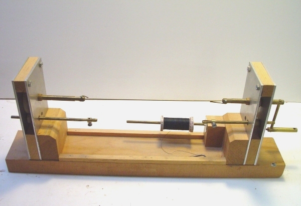
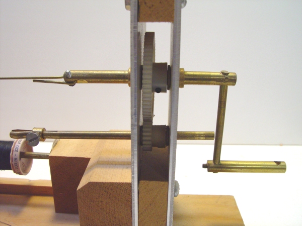
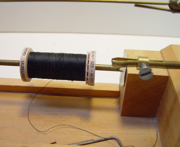
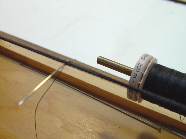
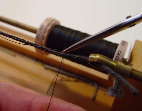
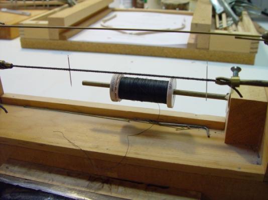
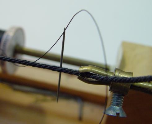
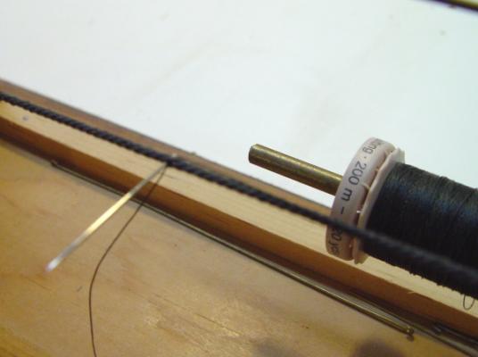
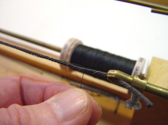
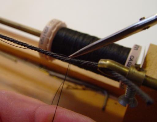
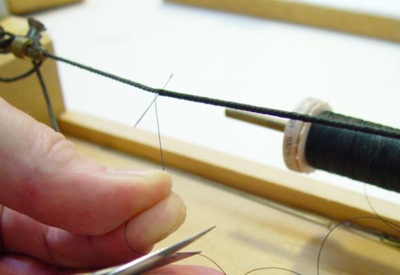
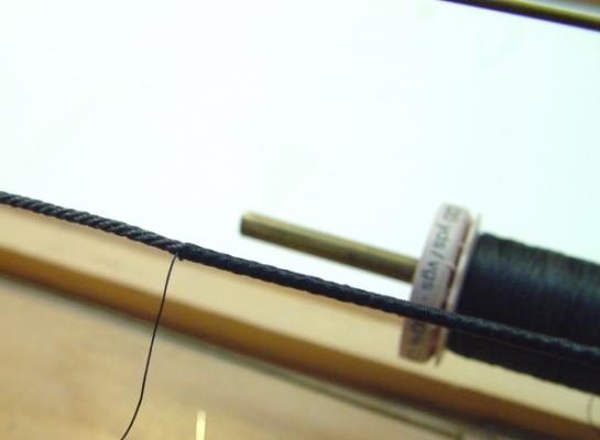
HMS Victory 1:96 Scratchbuild Project Part 14 – Serving Rope Posted to MSW 8/29/10 Some of the very first lines to be rigged required serving. Creating served lines on the model is simplified from what was done in real practice. Standing rigging that was subject to wear from rubbing or required additional protection was wormed, parceled and served. Worming refers to wrapping a rope of smaller size into the grooves in the main strands of the rope. The only lines on the Victory model that were wormed were the anchor hawsers and the mainstay. Others were too small for this. The next step, parceling, involved wrapping the wormed rope with tarred flannel – like tape. None of this was done on the model. Finally, the wormed and parceled rope was served. This involved wrapping it tightly around its circumference with small sized yarn. Many lines on the victory model were served – stays, lower and topmast shrouds, stay collars and all but the smallest that were specified for the treatment in the rigging schedule. None but the largest block beckets were served. The Serving Machine Some sort of device is needed to facilitate the serving process. Below is a picture of the machine I made for this. The basic principle of this machine is that a rope stretched and clamped between the two lower shafts, would be rotated in the same direction and at the same rate from both ends to avoid twisting the rope. Fine thread could then be closely and uniformly wrapped around the rope from a spool as the rope was turned. This is a closer view of the internals of the head end of the machine. A crank turns the shaft with the larger gear. This shaft is connected by a thick wire jackshaft to a large gear of the same diameter at the other end. These two gears rotating at the same speed drive smaller gears at each end on shafts to which rope is clamped. One turn of the crank gives, I think, three turns to the rope. Rope is held at the end of the shaft by jaws formed at the ends. The jaws are made tight on the rope by a threaded collar with a screw, which is slid forward. The screw is then tightened to hold the rope on the shaft centerline. At the other end, after clamping, the rope is pulled tight by sliding the shaft at that end backwards. With the right tightness on the gear set screw this can be done without having to tighten the set screw every time. Only enough tension is needed to keep the rope reasonably taut. The serving yarn used was very fine cotton thread. The spool was given its own shaft so it can unwind as needed. The Process First, the portion of a line to be served was marked out with a white chalk pencil. Often this was done by putting the line in place on the ship to get this right. Small sewing needles are passed through the rope between the strands at each ends of the area to be served. The rope is then clamped into the machine, which was clamped in a vise. This is shown below in the following demonstration. The end of the thread from the spool is then passed through the needle at the right hand end. It is then pulled through the rope and the needle is set aside. After being passed through the rope the thread is passed through the eye of the second needle and that needle is pulled through to a point where the thread is close, but not yet into the rope. The purpose of this is to keep the thread alongside the rope for the first part of the serving process. This is shown below. The next picture shows serving in process. The crank is turned so the thread gets laid over the top of the rope where it can be seen better. This helps assure that the turns are tight up against each other. After about ten or fifteen turns, the crank is stopped and the thread that runs along the rope to the other end is clipped off with small scissors as shown below. That end of the thread is now securely fixed under the first turns, leaving a nice neat beginning to the served portion. The serving then continues right up to the second needle at which time the thread is cut off as shown below, while maintaining a hold on the thread. The loose end is then passed through the eye of this needle and pulled through. It is then clipped off. The fully served line is shown below before being removed from the machine. I usually wait for the line to be installed before clipping this right up close. At that point the line is taut and in position, so it’s safe to put a tiny drop of CA on this end before that final clipping off. Eye splices were served by marking out just the loop of the eye itself. The needles were set at these points as above and the area between them was served exactly as above. Then the line was removed from the machine and the eye splice made. I will describe how this was done later. A needle was placed at the end of the area to be served below the eye. The eye itself was then clamped in the machine and the thread was tied to the bottom of the eye loop. The line was served up to the needle and finished off the same way. Where needed on stays, a mouse was formed in the serving machine in a much simpler way than the original. Thread was fastened at the mouse location and a bump was built up in the shape of a mouse by winding the thread over itself and touching it with a small drop of CA a couple times as it built up in diameter and shape. It was finished off with a clove hitch to secure the end of the thread. In the next part, I will describe how blocks and deadeyes were made. Ed Tosti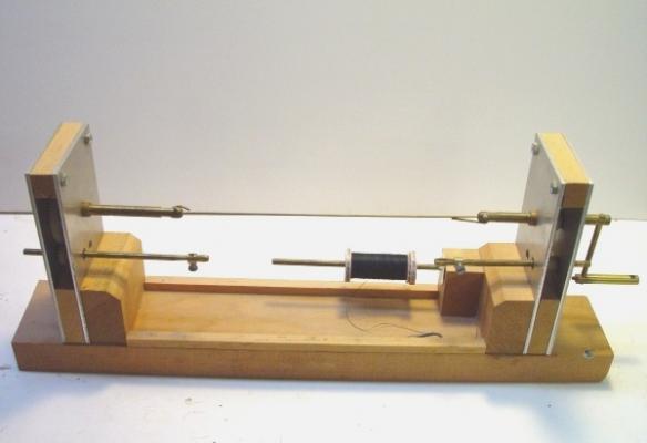


-
HMS Victory by EdT - FINISHED - 1:96 - POB
EdT replied to EdT's topic in - Build logs for subjects built 1751 - 1800
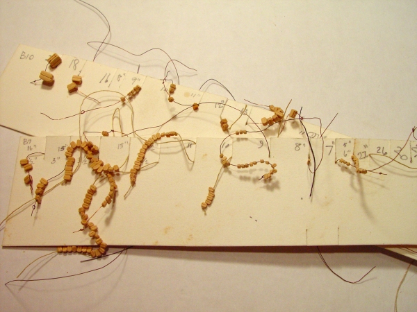
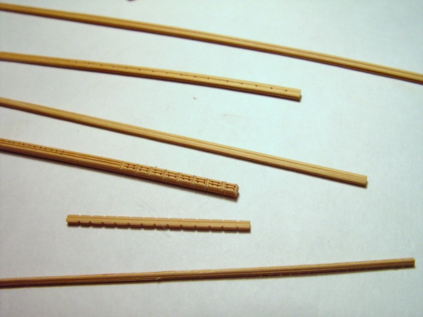
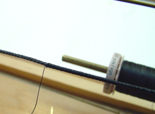
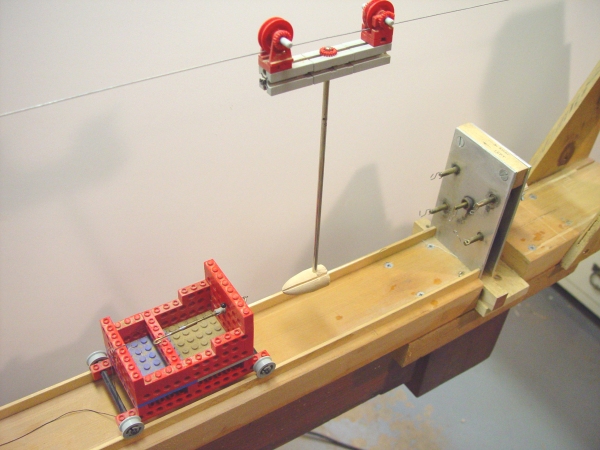
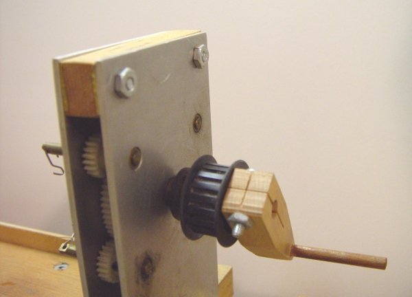
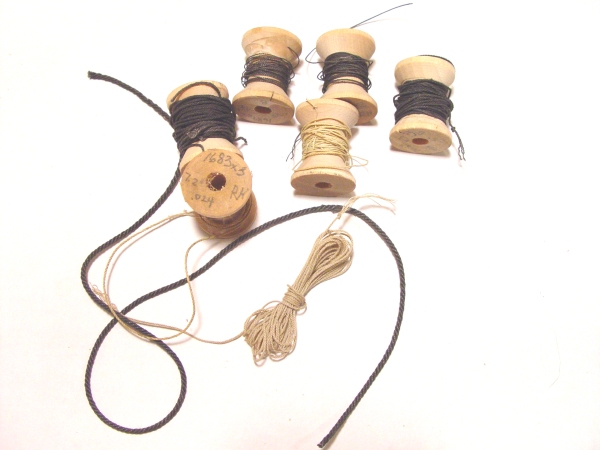
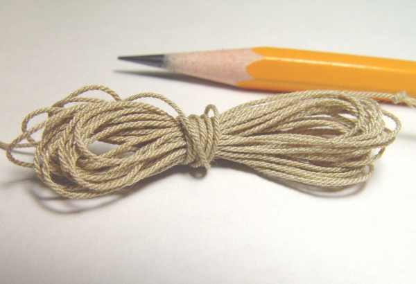
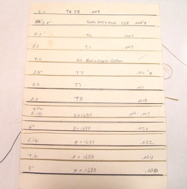
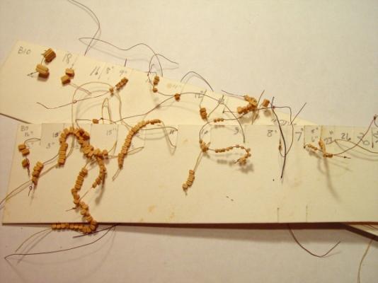
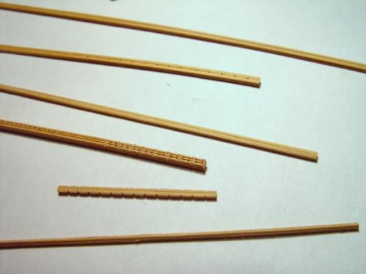
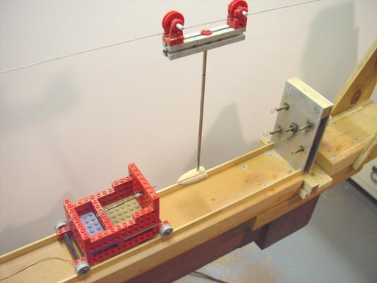
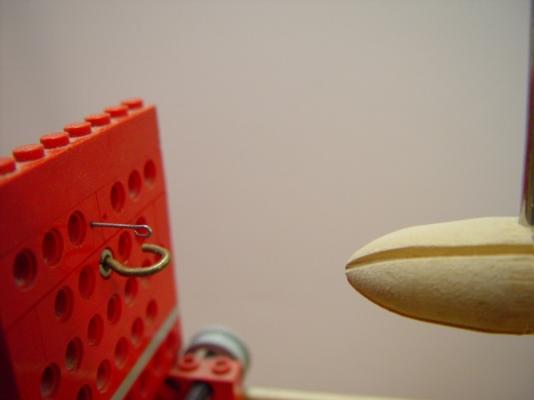
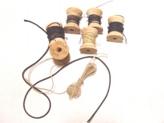
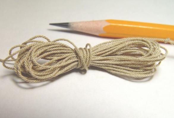
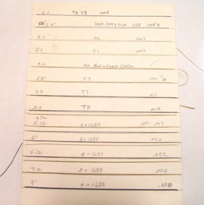
HMS Victory 1:96 Scratchbuild Project Part 13 – Ropemaking Posted to MSW 8/28/10 There is a lot of rope needed to rig Victory, even without the rigging for the staysails, jibs, and studding sails, which as mentioned earlier were not modeled because without sails this is not practical. The rope ranges in size from the 27” circumference (9” diameter) anchor hawsers, down to 1” for flag halyards. All rope size is designated by circumference and I will refer to sizes on the model this way, using full scale measure. The picture below illustrates some of this diversity of sizes and types. The largest line in the picture is the forestay, which is in a loop around the dense stack of shrouds above the foretop. This rope is 18 ½” in circumference. It has a bump in it called a “mouse”, which stops an eye splice. The stay is “served,” that is, wrapped with yarn, in this case very fine thread, from below the mouse around the masthead down to and including the eye splice. The smallest lines are the ratlines which are 1 ½” in circumference and tied around each of the shrouds with a clove hitch. The shrouds are 11” left handed, four strand cables, in pairs looped over the masthead. They are served from the masthead down below the height of the main yard. The first shroud on each lower mast is served over its full length. The sheets, which took the stress from the lower corners of the sails were among the largest lines in the running rigging. The end of the fore topsail sheets were 8” hemp. In this picture they rise up from blocks at the end of the yard where, in the absence of sails they are connected by a seized overhand knot through a loop of rope to the twin eyes of the clue line blocks, waiting for some miniature foretopman to untie them and make them fast to the corner of the foretopsail. . The standing rigging is black and the running rigging is hemp colored. The variety and complexity of all this adds a lot of interest to the model – and the modelmaking. The Ropemaking Machine Ropes down to 4 1/2” were made on a ropemaking machine, or model ropewalk, from small size linen thread. Sizes below 4 ½” were of mercerized cotton polyester thread. I will say more about this sizing and thread selection later, but first I will focus on the ropemaking machine itself. Longridge does a good job describing the ropemaking process and the machine needed and I have seen several good articles on this as well. I will describe what I did. Below is a picture of the heart of this machine. You can see from this that I was robbing my kids’ toy chest in making this. First, the bed of the machine is a 2X4 about 10 feet long into which two slots were routed lengthwise to take two 1/8’ wide rails. At each end of this there is a sturdy pylon with adjustable eyebolts that stretch a strong steel wire taut about a foot above the bed. The rails carry the Lego cart, which holds one end of the rope strands in a spinning hook. This cart moves forward toward the headpiece as the rope is being twisted up. The “high wire” supports a rolling device that holds a slotted mandrel to keep the strands separate and feed them into the forming rope. The string trailing behind the cart drops over the other end of the 2X4 and has small weights attached. These weights put tension on the strands to keep the strands from tangling together. They also resist forward movement of the cart to give proper tension in the rope as it is made. The headpiece component, shown closer below, consists of a central large gear with four planetary gears each with an extended shaft fitted with a stiff steel wire hook. The central shaft has a hand crank and is fitted with a timing belt sheave for connection to a motor drive. This drive (not shown) is made from an old sewing machine motor with an adjustable speed foot pedal. It can be attached differently to yield right or left hand rope by reversing the direction of rotation. Either three or four strands can be tied to the planetary gear shafts to make three or four strand rope. To make this machine, two aluminum plates were marked out and drilled accurately in a drill press to take the five shaft bearings at the right centers for the five gears. The gears are delrin on brass shafts and the bearings are brass sleeve thrust bearings. The two plates are spaced with shimmed wood blocks and bolted securely. The center gear is larger, I think 3:1, so, one turn of the crank gives three turns to the driven shafts. This assembly is securely bolted to the end of the 2X4. The last key component, and in some ways the most critical to getting good results is shown below. On the cart are two hooks, one for large and one for small rope. These need to be as free turning as possible. This helps get the twisting up started and keeps it going at a uniform rate. For very small work friction can be a problem. The small hook, made from a round-headed pin, is used for most of the rope. To the right is the mandrel, a smooth piece of wood shaped to a bullet point with four evenly spaced grooves around its circumference. These grooves come to a point allowing the strands to converge freely together when being twisted. I used the four-slotted mandrel to make all rope. An interchangeable three slotted version was made and is better for three stranded rope, but I seldom took the time to change them out. Making Rope Even with all this apparatus, I found that making small ropes is still an art form as opposed to a scientific repeatable process, especially in the small sizes. I will outline the steps and highlight the critical factors involved in getting successful results, but this is very much a trial and error, learn as you go process. First, a strand of linen thread is tied to the hook on one of the four shafts on the headpiece. I will discuss thread selection and size later. The cart is moved about seven or eight feet back and the other end of the thread is tied to the hook on the cart. The cart is then pulled back to put enough tension on the strand to make it straight and held in place with spring clamps placed in front of the front wheels. If four strand rope were being made I would loop the strand through the hook and take it back and tie it off to another on of the four shafts. Then a second strand is tied to one of the four shafts and taken through the hook and back to the headpiece where it is tied to another hook, trying to make the tension in all the strands as even as possible. Equal strand tension is the critical factor in this step. Next the three (or four) strands are distributed into the grooves of the mandrel, which is brought up to within an inch or so of the hook on the cart. It is important in this step that the height of the mandrel is the same as the hook. The crank is then turned by hand, or more normally, by the motor to start twisting the strands. Depending on the direction of turning, the linen strands may at first unwind before starting to twist up. Note that the clamps are still holding the cart. As the strands begin to twist and tension builds, the rear wheels of the cart will begin to lift. At this point the motor is stopped and the clamps removed. The tension on the weighted string at the back of the cart now becomes the critical factor. If weighted correctly, when the motor restarts the strands will continue to twist and the cart will soon begin moving toward the headpiece. Rope will begin forming between the cart hook and the mandrel, which will move toward the headpiece at a faster rate than the cart. When the mandrel reaches the headpiece, it is swung aside. The rope will now be about four to five feet long. feet long – 65 to 80 fathoms in real length. The rope end is held between two fingers and the strands are clipped off the hooks. A knot is then made in the rope end and the rope is tied to one of the four hooks. The hook on the cart is then stopped from rotating with a clamp and the motor is run again. This process tightens up the rope. The motor is then stopped and the rope is grasped at the cart end and pulled taut to help lock the rope fibers. It is then disengaged from the cart and pulled harder to tighten it further. It will stretch, but if it breaks you’ve pulled too hard. The rope is now made and stretched and can be removed from the machine. It will not unwind. It is now ready for the final step, coloring. Standing rigging was black and running rigging hemp colored. Right after the rope was made, it was dyed in one of these colors, stretched to wring it out, and hung up to dry. When dry it was stretched again, re-dyed and dried again if needed, and wound onto a labeled bobbin. Rope was dyed black with a diluted acrylic liquid artists color. Hemp coloring was mixed from acrylic designers guache then diluted. Acrylic artists colors are made from finely ground pigments, so unlike dye, they will not fade. With the diluted mixtures there is no noticeable stiffness in the rope from the acrylic polymer. Both colors were diluted enough so that the rope would show some contrast, with the crevices being darker. Black is not black black. Same with the hemp. Where thread alone was used, colors were selected to be close to the linen dyed hemp. The black thread is black black. Rope Sizes I used primarily two sizes of linen to make all the rope. Other materials could be used and I made some nice rope with other materials – cotton, polyester, etc. I was concerned about stretching, but after a couple years there has been none on the made rope or even on the plain thread that was used for smaller sizes. Based on this I would consider using other materials if doing this again, mainly because linen thread, even the higher quality type I used, has imperfections – bumps – which sometimes show up in rope. Below is a picture of some of the leftover linen rope. In this picture, on the end of one of the bobbins, you can see information about the rope on that spool – number of strands of which thread, right or left hand, and size. Here is a close up of some of the hemp rope. With only two sizes of thread, there were limits to the sizes of rope that could be made. The variables were, number of strands, size of thread, number of threads in a strand. The smallest made rope was 4 1/2” and was made from only two strands of the finest thread (1684). To set the sizes, rope was made by all the different combinations available, then each was measured with a micrometer and each size needed was assigned the nearest combination. The card below shows the assignments for the smaller sizes. This card was used throughout the rigging process to select the best size match for each rigging line. Below 4 ½” there are merely thread types, with their diameters. The larger sizes show the number of strands of which linen thread. The above sizes make up the bulk of the rope needed. Sizes above 9” were were listed on another sheet and made to size with more or bigger thread. In the next part I will discuss serving and the serving machine. Ed Tosti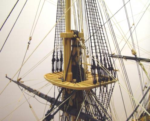

-
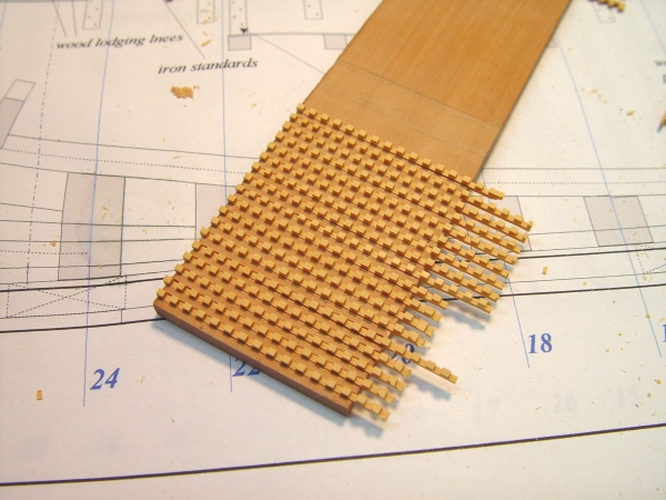
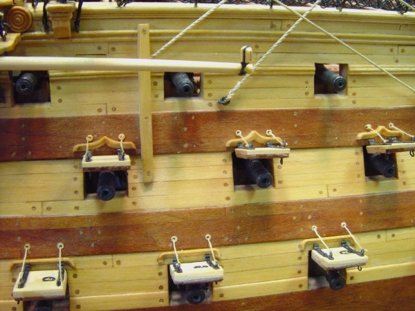
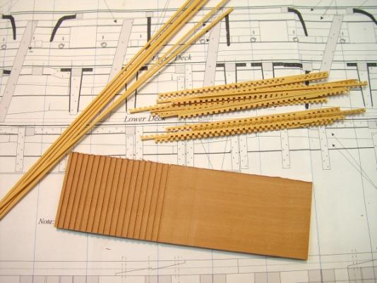
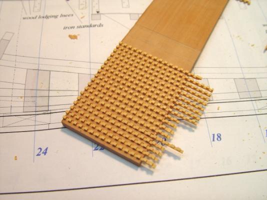
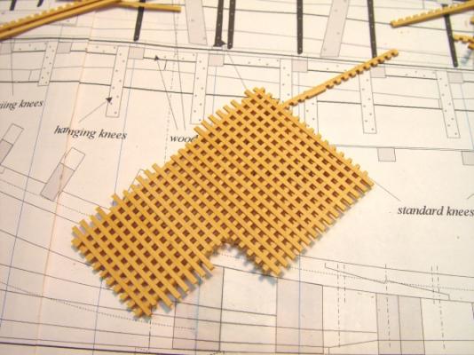
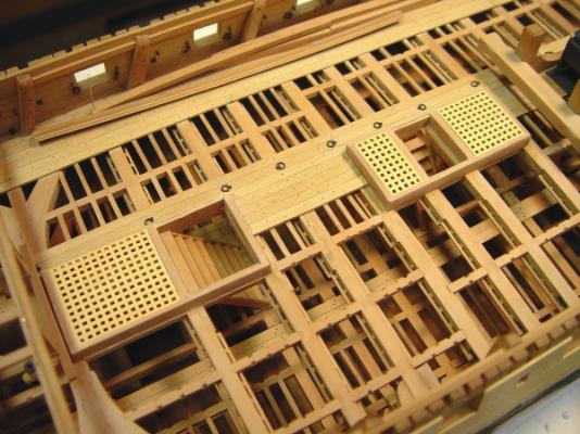
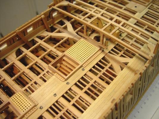
1:60 HMS Naiad 1797 Part 128 – Upper Deck Gratings, Shot Racks Posted 3/28/12 I wanted to model the gratings on the hatches on the upper deck in the waist. This reduces visibility down through the hatches, but there is a lot of open space on the starboard side to see down into the hull. These needed to be installed before the crankshafts for the pumps. I used the method that I am sure many have used to make these. The first picture shows the key parts ready for assembly. The supporting ledges and the slats are 2 ¾” wide. The ledges were made deep enough to allow them to be rounded up to match the head ledges of the hatches. The large piece in the lower part of the picture is the assembly jig. All these pieces except the slats were cut using the set up in the next picture. A square of Plexiglas was cut to fit the saw table. The saw was fitted with a 2 ¾” (.045”) slotting blade. A dado was ripped into the Plexiglas to fit a guide strip and the opening for the blade cut into it. The boxwood stock was then ripped by guiding it on the wood strip. There is nothing new about all this. The boxwood was then ripped into 2 ¾” wide strips using a much thinner blade. These were then placed in the fixture as shown below. The fit in the fixture is loose enough to slide the ledges back and forth. The slats were then fit into the notches. These were a tight fit, but a thin film of glue was applied to the bottom face to help keep the assembly together when removed. The next picture shows a section of grating before sizing. The next picture shows the gratings fit to the three hatches in the waist. The bottoms of the ledges were sanded until the center of the grating was flush at the head ledges. They were then glued in and the round up sanded top match the curve of the head ledges. They were then finish sanded and polished up. Shot racks were then made and added on the decked side only. The shot holes were made with a cannon ball sized spherical cutter in the milling machine, using the Sherline sensitive drilling attachment so the holes could be stopped at a uniform depth - about 1/3 the diameter of a ball - into the edge of a wide piece of pear stock. The strips were then ripped off, cut to length, rounded and glued in place. They were omitted from sides of ladderway openings. Cheers, Ed

-
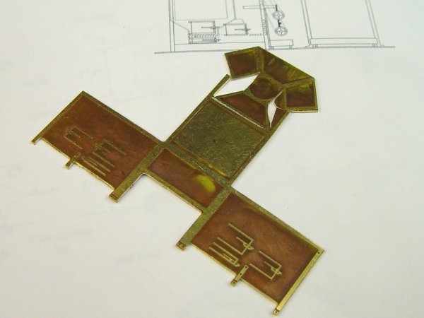
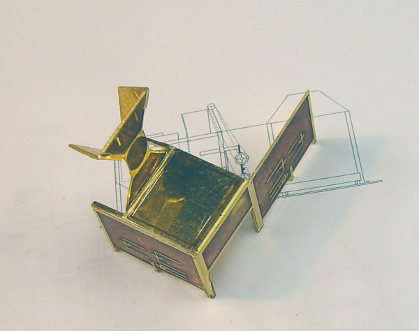
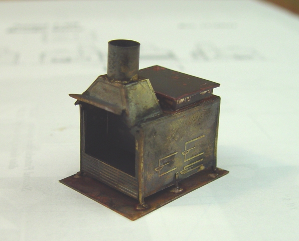
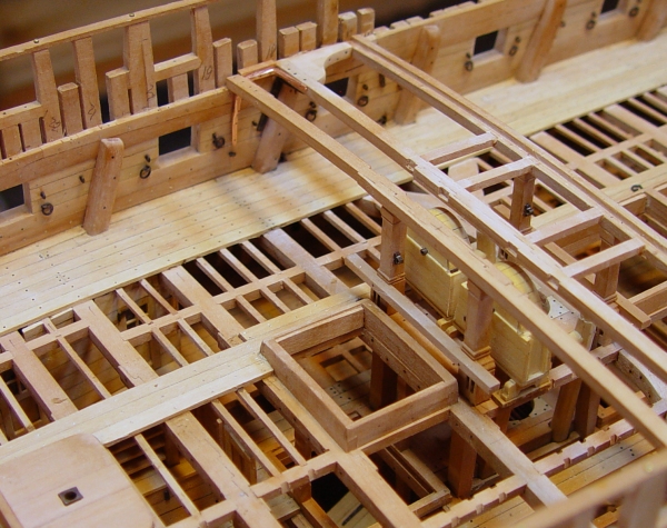
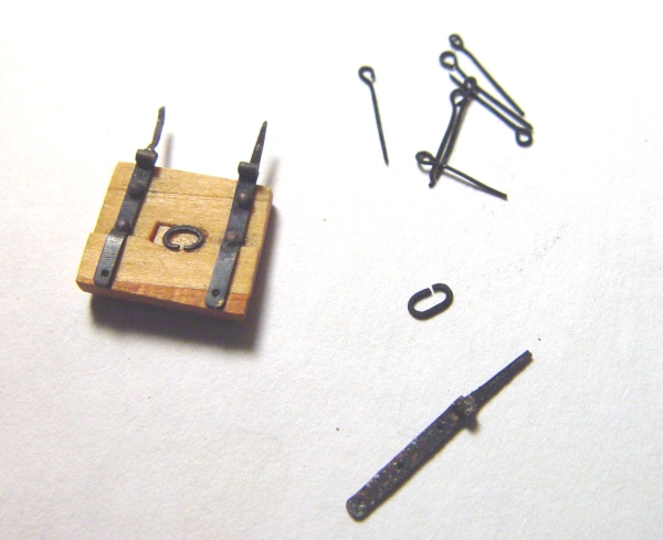
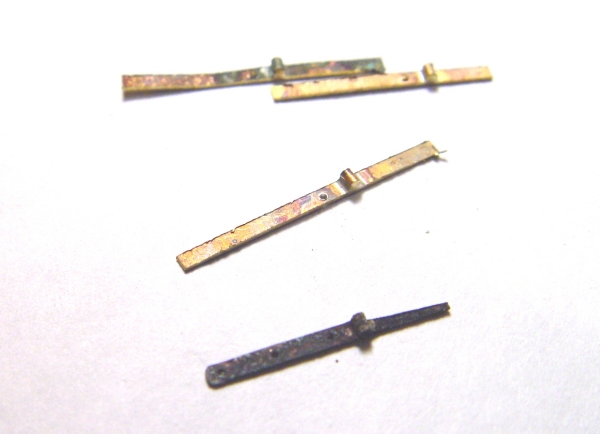
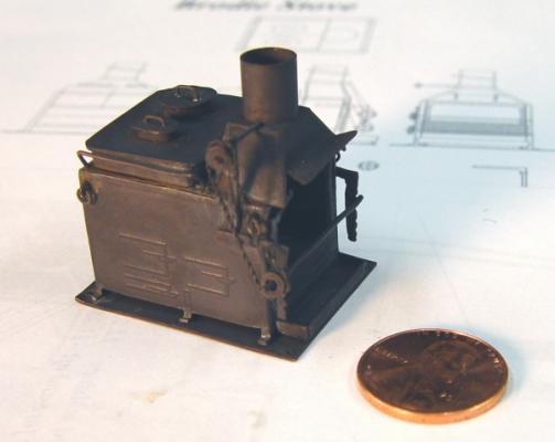
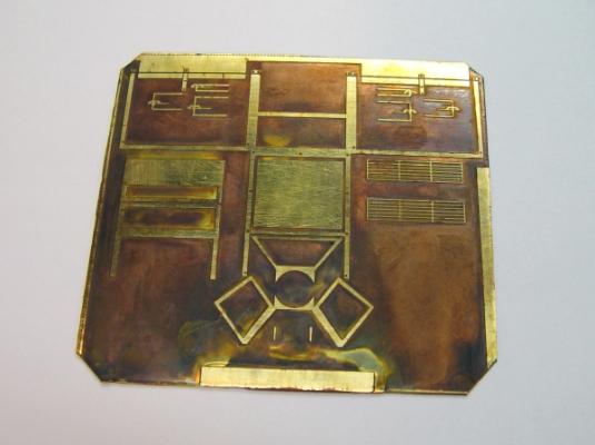
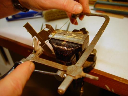
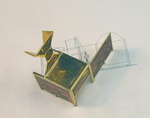
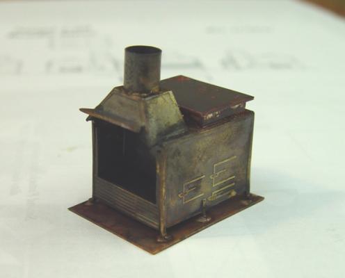
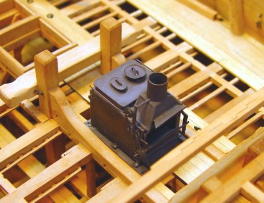
1:60 HMS Naiad 1797 Part 127 – Mr. Brodie’s Stove Posted 3/25/12 It has been two weeks since the last post. I’ve been working back along the forecastle with beams and the upper deck detail below them. The picture below shows beams 5 and 6 with the copper knees - not yet blackened. The foremast partners were installed before these beams and are partly visible. Beam 7 and 8 were also installed, but that was as far as I could go until the Brodie Stave was made and installed. The Brodie Iron Stove had become the standard by Naiad’s time. It was introduced in the 1780’s but was not dissimilar from types used up to that time. An iron housing contained two built in cauldrons for boiling water. One can imagine 250 pounds of salt meat being loaded into this daily. Below these pots was a firebox with doors on either side for charging fuel – wood or coal. A smaller door below the firebox grate was used to remove ash. A contained oven, accessible from doors on either side, could be used for baking. The front of the stove, the range, was open in the front and was equipped with arms for hanging pots and one or more rotating spits, turned by chain pulleys driven by a vane inside the stack. There was a drip pan under this spit. The finished model of the stove for Naiad is shown below. I have been working on this for the last few weeks. I decided to make it from photo-etched parts, but it proved impractical to photo-etch all the pieces then solder these very small parts together. I won’t go through the gory details of the learning process or the earlier failed attempts. I finally settled on making the basic stove structure from a photo-etched plate that could be folded up, origami style, into the basic stove, then making the detailed parts separately. This version has been in production for about a week The next picture shows this photo-etched plate, which was the starting point. Some of the stove detail is engraved on the sides – the firebox and oven doors and the front grille. The necking down of the stack transition is the odd part in the lower center of this picture. The next picture shows the basic shape mostly cut out. The fold lines were etched out on the back and also one on the front. In retrospect all the etchings could have been deeper. The next picture shows some of this being cut out with a jeweler’s saw. In this picture the front vent flap sides are being cut so it can bend up over the stove opening in the front. This piece was made from .032” brass. It might have been better to use a thickness closer to .020”. My early attempts were with much thinner material – too thin, but this thickness made the silver soldering, especially the fastening of the small details, a lot more difficult. The next picture shows the stove in the process of being folded up. The edges along the joints had to be chamfered back to make a tight fit along the seams. The next picture shows the basic stove after silver soldering. At this stage the internal partitions, the stack, the boiler top, the range grille and the base plate are attached. This soldering required high heat – a regular sized propane torch – hence the blackening. This was pickled off between soldering steps using Sparex dip. Finally the brass-copper fabrication was blackened with dilute Hobby Black. It took about an hour to turn the final shade – shown in the second and the next/last picture. The last picture shows the finished stove in its final position between the bitt standards on the upper deck. The base plate will be bolted through the deck. The upper stack will be added later when the forecastle is framed. Getting this built was a major milestone. The next big project is the capstan. Cheers, Ed

-
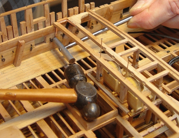
1:60 HMS Naiad 1797 Part 126 – Upper Deck Detailing (5) Posted 3/10/12 Before moving to the bow, I needed to install the third beam over the mast partners, above the upper deck. In the first picture the beam is ready to be installed. Because of the closeness of the beam ahead of it, this beam has U-shaped iron lodging knees. The hanging knees are also iron. These were bolted on before installation. The next picture shows the beam glued in place. Quite a few bolts need to be installed to complete the installation of this beam. The next picture shows one of these bolts being driven in. The hole in the end of the leg, in this case the bottom, was drilled first. Its bolt of copper wire was then pushed in with pliers and driven in as shown. The other holes could then be drilled without fear of the arm moving off the first hole. The steel hammering aid shown in this picture was made from drill rod for cases like this, where there is no room to hammer directly. A variety of devices – punches, bent rods etc. - are used for the different access needs. The holes are (usually) driven into but not through a frame, so the bolt can act like a nail. The horizontal holes between the beams, were, of necessity, drilled at a slight angle. With this done, the work moved to the bow. The next picture shows the catheads being glued to beams 2 and 3, there is no beam 1 – a design change. The catheads are identical mirror images. At the bottom they meet on the centerline under beam 3. The ends were then checked for length by measuring out from the side and with a square up from the drawing. The fore and aft angle was also squared up from the base drawing and the height of the ends checked.. The next picture shows the finished installation. Holes have been drilled down through the beams for bolts. This picture also shows the framing around the opening for the bowsprit. Beam 4 has also been positioned against the wood lodging knees. Beam 4 supports the upper end of the bowsprit step, which is shown in the next picture. This picture was taken when the rabbets for the manger partitions were being cut. A bevel was first pared on the lower forward corners. The bevel is shown on the right side in this picture. A groove was then pared down the center of this using the V-gouge in the picture. The sides were then pared with a chisel to a square rabbet as shown on the upper corner in this picture. A traced circle from the dummy bowsprit is just visible in this picture. It was used to center the square opening for the tenon at the foot of the bowsprit. The next picture shows the step installed. This picture also shows the “cast” iron knee on the aft side of beam 4. This avoids the gun port and serves as both a hanging and lodging knee. It has not yet been bolted into the side in this picture. The last picture shows the manger wall on the port side. The inside end fits the rabbet in the forward corner of the step. The outside end slides into a vertical cant at the side. The cant and the planking were installed as a unit from above. In this picture the beams at the bow seem to have less round up. I believe this is photographic distortion – but I will re-check. Ed


-
HMS Pandora (1779) CAD build log
EdT replied to SketchupModeller's topic in CAD and 3D Modelling/Drafting Plans with Software
A very interesting project I look forward to your progress with it. It my be helpful - perhaps you already know this - that Pandora was a member of Porcupine Class of 1776 - a Williams design. I mention this because The Shipbuilders Repository 1788 uses Porcupine as its example for a 24 gun frigate, which means that all the information included will be specific to Pandora as well. This includes the Table of Bodies and all the scantlings (sizes of every timber) - including those that are ship specific. If you can get your hands on a copy, it may be helpful. Ed -
HMS Victory by EdT - FINISHED - 1:96 - POB
EdT replied to EdT's topic in - Build logs for subjects built 1751 - 1800
HMS Victory1:96 Scratchbuild Project Part 12 – Masts, Spars and Rigging 1 Rigging Overview Before beginning the rigging, a number of questions had to be answered about the extent of rigging to be modeled. First was the question of sails. I knew I did not want to model sails, even though they provide an opportunity to model a lot of very interesting rigging features. Having decided against them, some rigging could simply not be modeled effectively, for example, staysail halyards and sheets. Beyond this type of rigging on staysails, jibs and studdingsails, I decided to model everything else on the rigging list. This list can be found in Steele’s Elements of Mastmaking, Sailmaking and Rigging and is duplicated for Victory in John McKay’s book in the Anatomy of the Ship series. As shown partly in the picture above, Victory’s rigging consists of hundreds of lines of many different sizes. Some are right hand three strand hawser laid, some are four-strand left hand cable laid, with several varieties in between. Each line has a variety of blocks, deadeyes, hooks, etc. associated with it. Each line has a specified length and some are deceiving, introducing the possibility of coming up short after putting a lot of work into a line. All this information is included in Steele’s for each class of ship and in McKay for Victory. To make the use of this information easier, I made an Excel spreadsheet, specific to Victory to make all this information usable, to help total up numbers of parts, rope lengths, types and treatment and to provide a checklist where fabrication and erection of each item could be checked off. This was an invaluable aid and a constant fixture on the workbench for years. A sample page from this 20-page document is shown below. Longridge was the other indispensable resource. His book covers every single item of rigging in a simple ‘how to do it’ style. Other important references I used were the McKay book and James Lees, Masting and Rigging of English Ships of War 1625-1860. The order of rigging is often discussed. I followed three simple rules in the following order. First, fore to aft. Second, bottom to top. Third, standing then running. I applied this approach to masts and spars along with the rigging, because so much rigging is attached to these before erection. So, for example, the main topgallant lifts were made and installed before the lower mizzen mast. Mixing the work between spars, rigging and other items like the tops and cross trees also helped relieve potential tedium. This approach worked well with only a few awkward situations. These were overcome with some good long tweezers, surgical clamps, long curved needles and a dose of patience. Materials need to be decided. I elected to make all the masts, tops, cross trees, caps, parrals, blocks, deadeyes, and most other accessories from boxwood. Yards, except for the lower studdingsail booms were made from Gabon Ebony. In larger sizes, 4 ½” circumference and above, rope was twisted up on a ropemaking machine from fine linen thread, three or four strand, right or left hand as required, if doable at the scale. There is actually a lot of two-strand made rope on the model, because it looks better than plain thread. Plain thread, mostly mercerized cotton polyester was used for the smaller sizes. The smallest cotton thread I could find was used for serving. Later, I will describe two machines that were made to: 1) make rope, and 2) serve rope. Shaping Masts and Spars Almost all of the masts and spars have some variation of diameter over their length, for example yards are tapered from the center out. Most have either an octagonal or square section somewhere along their length or a combination of the two, for example, topmasts have a square of octagonal shape at the bottom, a flared octagonal shape under the cross trees and a tapered square section at the top. For these reasons all these pieces were made by hand. The process is simple and widely used, but I will describe it for those who may not have had a chance to try it yet. First, a straight, straight-grained piece of wood, in my case this was box or ebony, is cut square on the circular saw to slightly over the final maximum dimensions. This is then planed down square to the maximum diameter of over its full length. The ends are then center-marked with a cross at the center of the breadth and width (not corner to corner). Keeping these marks in the center of each side as the work proceeds is important to assure that the finished spar is straight. The squared-off blank is then marked at points of decreasing thickness, or at points where it transitions in shape, along its length. The square is then shaped on all four sides down to these dimensions at these points, always making sure the center marks at the ends remain centered. The spar is then placed in a v-shaped groove in a jig rotated so one of the corner edges faces up. Using a small plane, scaper blade or files, that corner is taken down to the correct final dimension. Doing this to all four corners yields an octagonal shape. These tools Tools used for this and three sizes of jig are pictured below. The plane blades are kept very sharp and only fine shavings are taken. The rectangular scraper blade is a type commonly used in furniture making. The scaper edge is filed square, then honed square on a flat fine sharpening stone. I use a soft Arkansas stone for this. A burnishing tool, consisting of a polished hardened steel rod is then used to form a small curl on the edge of the blade. This curl does the scraping. In the next steps the eight new corners of the round sections are taken down to yield sixteen faces and corners continue to be taken off until the final round shape is reached. Some sections are left square, others octagonal. The transitions are then worked with a file, the spar cut to length, other details added, and finally polished ready for rigging out and installing. All masts and spars were made this way. Lower Mast Cheeks Making the lower mast cheeks presents an interesting problem. The inside of the cheeks for the model are made concave to fit snuggly on the mast. There is one for each side of the lower masts and a rectangular section at the top on which the beams of the top platform rest. The cheeks taper to a narrowed shape, fore and aft, at their lower ends, and also in the side direction. They were formed in one piece, turned to shape. The fore and aft narrowing was planed off after turning. Following is the process used, essentially as proposed by Longridge. The lower main mast with its cheeks installed, with the framing for the top in place, is shown below. The cheeks on either side of the mast and the rectangular section at the top were made from a single piece of boxwood slightly longer than the length of the cheeks, squared to a dimension slightly larger than the top rectangular section. A long hole is bored down the center of this piece lengthwise to the diameter of the mast in this area. For my model this was 3/8” for the fore and main, and 24” for the mizzen. This was a convenient coincidence that allowed me to drill these with long brad point drills of those sizes. The resulting piece was then put over a mandrel of the same dimension as the hole (a medium tight fit is desired). The mandrel was then set up between centers in the lathe, as shown below, and the piece turned down to the shape of the cheeks. The cheeks get very thin towards their bottoms, so very light cuts must be taken in the lathe, or the problem shown below is likely to result. This process wastes a lot of costly boxwood even when successful, so breaking the parts adds insult to injury. When the pieces are finished turning, they are planed down on the fore and aft faces to yield the shape of the cheeks. These parts will fit neatly over the mast, as shown in the picture below. The cheeks are fit temporarily in this picture. Before final attachment, metal rings needed to be formed, soldered, blackened and fixed on to the mast under the cheeks. After the cheeks are installed others are fit over it. In my case these rings were thin enough to fit under the cheeks without causing a gap to show. The joints in the rings were hidden under the rubbing paunch, a timber that fits on the front of the lower mast. The finished lower foremast is shown below. Iwill not discuss the making of spars any further, but if there are questions, please ask them and I will be glad to discuss those issues further. I will add a few more pictures to show some of this work. The above picture shows stiffeners being added to the top decking of the main top. These structures were very lightweight, basically just crossed members of thin planking on a grid of four horizontal crossed timbers. The seams in the planking are black paper. The side rails are slotted to take the topmast deadeye chains. Rounded bolsters are placed on either side of the lower mast open to prevent chafing of the shrouds. Another timber across the back wil be drilled for handrail stanchions. Above is the parral holding the spritsail yard to the bowsprit. These were fitted to all but the lower yards and allowed the yard to be raised, lowered, and rotated easily. The wheels for these very small working parts were turned from boxwood and drilled in the lathe before parting off. The trucks were shaped and drilled in a thick piece, then sliced off on the circular saw to assure a similar shape to all the pieces. They are then held together and bound around the mast by rope. Note the center section of the spritsail yard is octagonal in shape. This was true of all yards. The multi sided polygonal shape can still be seen on the round part of the bowsprit above the parral. The iron ring just above the parral is a part of the traveler for the jib. The knotted ropes in these pictures are the horses for the jib boom and the yard. These were of the smallest made rope on the ship and have only two strands – a modeling configuration only. Above is the finished fore top. The holes through the aft hand rail and the lower horizontal piece were drilled through one piece, which was then slit into the two parts. This assured perfect alignment of the holes so the rail stanchions would be vertical and parallel. The toggles on the decking between stiffeners support rigging blocks suspended below the top. These were all put on before installation of the top itself. The vertical battens around the square top section of the lower mast fit over the square iron straps and to absorb the rubbing of the lower shrouds. The two pair of burton pendants have been lashed together and put over the mast to be following later by the paired shrouds. The cap on top of the mast has a bolster on top with round grooves for slings, which will be put on later. Above are the finished fore crosstrees. Note the sheave in the bottom octagonal section of the fore topgallant mast. This was provided for raising and lowering the mast into position – a frequent activity at sea. The hole in the cap and the square opening in the cros trees were just large enough to allow the mast, including its flared out section at the top to be dropped when a supporting fid, just visible at the bottom of the lower square section, was removed. In the next section I will discuss rope-making and ropemaking machinery. Ed Tosti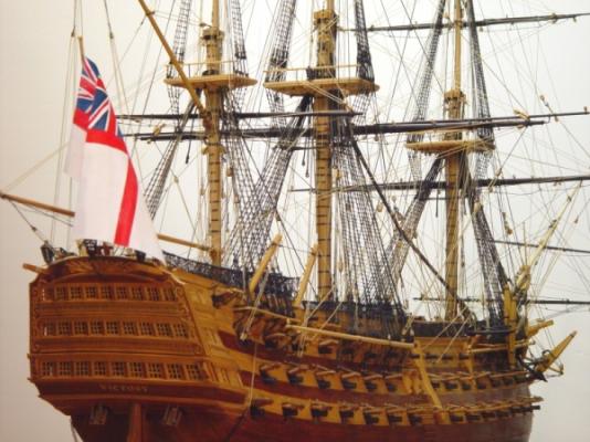
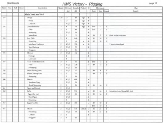

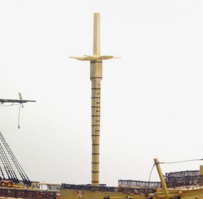


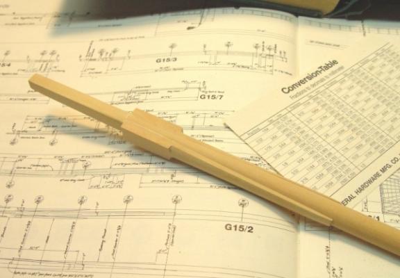
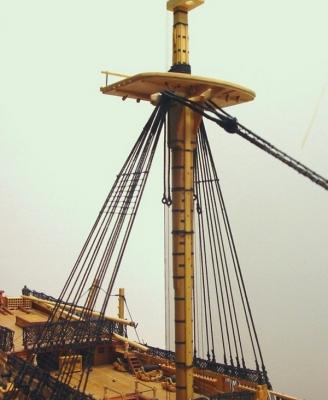
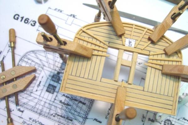
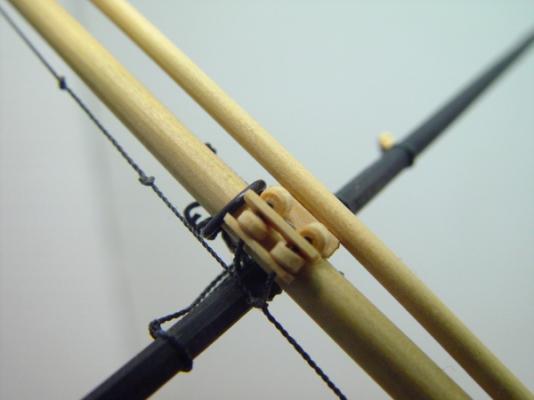
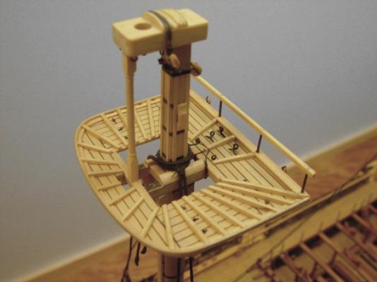
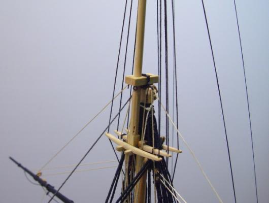
-
Lovely work. I really like the carvings. Ed
-
Martin, Yes, I was referring to an Archimedes type drill. However, in almost all cases I use a small rotary tool to drill holes. The ones I have are Wecheer - they are less than 1" in diameter and have virtuall no "kick" when placed over the wood and turned on. The copper bolts, with some exceptions on size are made with 22-gauge copper wire. Off the spool this is about .025". I pull this with one end in a vise until it breaks. This is to straighten and stress-harden it. After this it is reduced in size to about .022". This is about the same as a #74 drill. I drill the holes through the beams, and into the frames with that size drill. The holes through the knees may be one size larger. However, drills can make holes larger than their diameter, so the important thing is to use a drill that will give a sliding fit - with some resistance in the wood - so the wire can be pushed through the beam or into the bottom of the hole in the frames with pliers. On bolts through the beams, I cut the back side off flush and cut the wire off about 1/64"+ above the face of the iron knee. The beam is the laid on a metal surface and the wire over the knee peened with a hammer. If the top bends, its too long. On bolts into the frames, the hole is not driven all the way through - unless you have an extra pair of hands and access to provide backing for peening. In this case, I cut a sharp point on a length of wire with clippers then push it to the bottom of the hole with pliers, then clip off the top above the knee face - you will have to experiment to determine how much to leave - then tap it into the wood to peen over the top and drive the point into the wood. In either case the knees are held securely. I suggest testing this until you get a combination that works. Good luck, Ed
-
Gary, your work has been an inspiration to me. Thanks for reposting these pictures again. Ed
-
HMS Victory by EdT - FINISHED - 1:96 - POB
EdT replied to EdT's topic in - Build logs for subjects built 1751 - 1800
HMS Victory 1:96 Scratchbuild Project Part 11 – Gunport Doors and Quarter Galleries Posted to MSW 8/24/10. The topics covered in this part are both somewhat out of sequence. I was going to cover the gun doors last because installing them was the very last task in completing the model. This was left till last to avoid the mass of rigging lines getting fouled with the doors, having to be untangled, or worse, breaking a door. However, some interest was expressed in this, so I have moved it up in the sequence. Interest has also been expressed in the quarter galleries so I have added them to this part. They were built when the planking and details on the sides were done. Some of their construction was similar to what I described in the section on the stern galleries, some had other issues. The Gun Doors Although in this picture there is a bit of overexposure on the tops of the doors, they were planked on their outer face with the same boxwood and cherry as their surrounding planking. In fact, when closed the doors would match their surroundings, thicker if cutting a wale or the black strake just above the main wale, as seen in this picture, and of the same wood. Making the doors was pretty straightforward. They consist of two layers of plank set at opposed angles. On the model the inside layer was cut from a single piece of cherry, 1/32” in thickness. The sides of the ports are vertical, since they are flanked by the frame timbers. The sills and lintels parallel the respective gun decks, so some of the ports have a slight trapezoidal shape, more at the fore and aft ends of the ship. Note that they do not parallel the sheer. This means that the outside planks of the door will sometimes be at an angle to the sills, where the sheer is more pronounced compared to the deck line. To get this correct the cherry inside blank was fitted to the port and marked at the planking seams on each side. Planks of the appropriate thickness and wood type were then glued on so their seams would match the marks. Excess at the sides was then trimmed off. The door in the picture below, which somehow got mislaid during construction, shows this slant in the planking and the difference in thickness and wood. This picture also shows the closed vent opening, which was a feature of the lower gundeck doors, and the somewhat crudely made horseshoe hinge for this. The hinge was made by elongating a ring of the type cut for ringbolts and flattening it with a hammer. It was then glued on with CA. The other items in this picture are the very small eyebolts which were fitted at the bottom edge of the doors both top and bottom. These were formed from brass wire with a pair of small needle nose pliers which had been ground down at the ends to a small point. I will show these pliers later in the rigging discussion. Four of these were inserted in holes after the hinges were installed and glued with CA. I discussed making an applicator for very small drops of CA in a previous section. Finally there are the hinges. One is shown at the lower right in the above picture. Two are shown on the doors after bending their profile to fit the wood thickness. They are attached by two small brass nails each, and further secured at the ends with the top eyebolts.] The Hinges Proportionality in the hinge detail was the principle factor in making these. This out weighed any thought of making working hinges at this scale, so a dummy hinge that would look like the original was adopted. The hinges were made by taking a strip of brass plate, the thickness of the hinge and about 1” wide by a couple inches long. A piece of straight brass wire was then silver soldered down the length of this strip at its center. The strip was then clamped firmly on top of a block of wood and the hinges were sawed off to the correct width. The resulting hinge blanks are shown below. The hinges could be sawed manually, but I used a thin saw blade set up in the milling machine to slice these off. This assured the exact same width and minimized cleanup of the sawn edges. The three holes were then drilled in each hinge. A small drilling jig was made so these holes would all be spaced uniformily. The blanks above have had their first hole drilled and the finished hinge at the bottom has its final three holes and has been blackened. This hinge has also been filed down in size on the portion that will fit into a hole in the side of the ship. These holes were made small so they would not be visible when the doors were pushed in. The holes were spotted for drilling on the side using the final assembled door for that port as a marking guide. The picture below shows some more doors and the underside eyebolts. Note that the ports in the waist do not have doors. Gun Door Lift Tackle Making and installing the rope lifts to raise the doors presented the interesting problem of how to fasten the ropes inside the hull. The two lower deck aft chase ports under the wing transom were done simply by pushing line into holes and grasping the line inside with tweezers, then tying the two inside ends together, pulling the line out and tying it to the top door eyebolts. This would not work for the side ports for a number of reasons so another solution was needed. The sleeves on the real ship protrude a bit from the side. They were probably lead liners through holes into the gundecks, where the tackles would be suspended from the beams. All I needed to do was simulate the sleeves and secure the lines inside. This was done by making small boxwood sleeves. These are about the size of the sleeves on the real ship and have a hole drilled through them just large enough to take the lift line. Below is a picture of some leftover sleeves and a piece of blank from which they were cut. The sleeves were made by drawing strips of boxwood down to the outer diameter of the sleeve to form a long thin dowel. A drilling guide was then made with a hole through it the size of the sleeve. This guide was then secured in the cross feed of the Unimat. Actually, the guide was secured first, so the hole would be exactly centered in the lathe. The drawn boxwood dowel was then placed in the three jaw centering chuck in the lathe. The tool rest was moved toward the headstock to bring the dowel to the front face of the guide. In this operation, the hole through the guide, which just fits the boxwood dowel, keeps the spinning dowel centered for drilling. The small drill bit in the headstock was allowed to protrude only enough to drill one sleeve. This reduces drill wandering in the hole. To drill a hole, the tool rest was backed toward the headstock until the dowel was even with the face of the guide. The tailstock was then advanced with its handwheel to drill the hole and then pulled back. The picture below shows the next step. In this picture I am showing how a sleeve was parted off after drilling using a razor blade in a slot set back from the face of the guide by the length of the sleeve. Very gentle pressure is used with the lathe turning. It is very easy to crush these small blanks. When the sleeve was cut through the tool rest was moved toward the headstock and the finished sleeve pushed out. The next sleeve was then ready for drilling. A razor blade was used for this because even the finest saw I had fractured the fragile sleeves. To install the sleeves and the line, holes were drilled in the side of the ship above the hinge holes. These holes, of course, matched the diameter of the sleeve. The line was then pulled through the sleeve and knotted on the inside end so it would not pull out. The sleeve was then dipped in Titebond glue and inserted into the hole. Later when the glue was set, the doors were inserted and positioned and the lines were tied to the door eyebolts, with proper tension on the line to maintain the door height. The picture below shows some more doors, including the vertical opening bridle port doors doors of the infirmary on the middle deck. Quarter Galleries The main issue I had in making the quarter galleries was the overall shape. The drawings I had were not overly detailed, and although I used a very simple underlying structure for these, a number of factors affect their final alignment and appearance. The slight s-shape vertical curve of the hull combined with the slant and step tiered construction of the three levels makes the galleries a bit hard to visualize and depending on the view point they may look correct or incorrect because of these factors. Also, the outward curvature of the rail structure affects the window slant and to some degree where the columns between the windows end up if the parallel window geometry is maintained. The best advice I can give about these is to get the best set of horizontal rail profiles and fore and aft vertical sections of these that you can find. I have mixed feelings about my final results with these, but these were not negative enough to redo them. This picture was taken during construction of the starboard galleries. Curved sections of rail were cut to shape and moldings were scraped on the outer edges with molding scrapers. These were made heavy enough to provide the underlying structure of the gallery. They are held in place with pegs and glue. Curve sections of thick cherry were then shaped and inserted between the rail sections. The balusters were carved in exactly the way described for the stern galleries, except that these balusters are slanted backwards and inwards along the rail, with the slant being more pronounced at the fore end. The picture below shows the slant of these balusters. This picture also shows the slant of the window columns, which were held nearly parallel with each other, with their bottoms and tops being set back by the same amount where they meet the rail. Finally the window frames and mullions were installed in much the same way as the stern galleries, except that with a lot more slant, the interlocking notches needed to be cut on angles. The above picture shows the alignment of the galleries. Its close the original, but but perhaps not perfectly matched. I’ll let the reader judge. The following picture has been mirrored to align with the picture above. It is actually of the starboard gallery. It is taken from a lower angle than the above picture and from further astern. I believe the way is now clear to move on the masting and rigging and I will start that in the next part. Ed Tosti
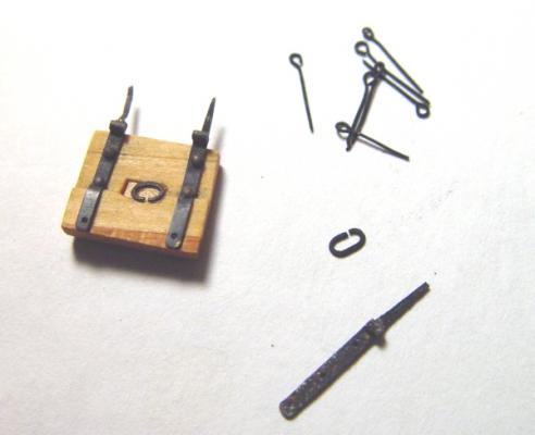

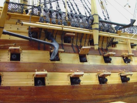

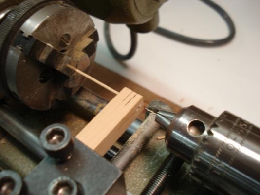
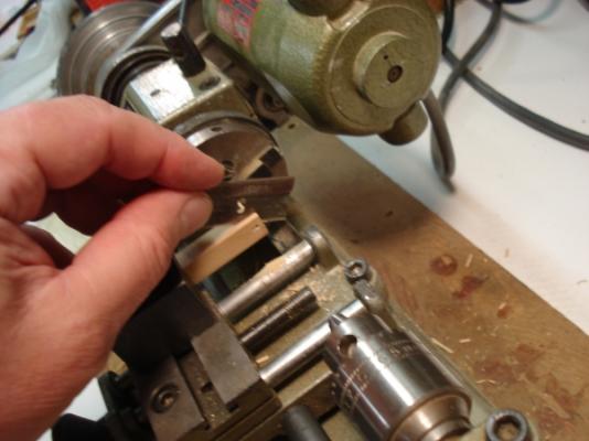
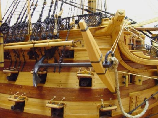
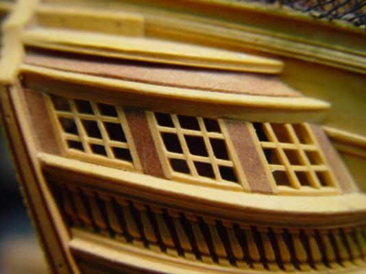
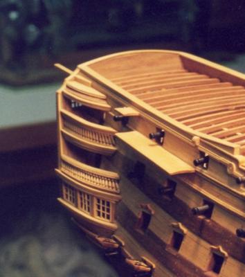
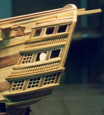
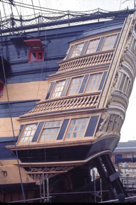
-
1:60 HMS Naiad 1797 Part 125 – Upper Deck Detailing (4) Posted 3/6/12 With the decking completed in the area of the riding bitts the crosspieces could be installed. The first picture shows the aft cross piece glued and clamped. The height of these above the deck is set by the wood shim in the picture one on each side. There is an eye in the cross piece at each end, to take a hook that is bolted into the bit. I installed the eyebolt with the hook on the cross piece first. Then when the glue was set, hammered in the bolt through the eye in the hook. This was easier than trying to engage the hook in the eyebolt after both were fastened in place. I did try that. In the next picture the adjacent gun port is coming in handy to drive in one of the hook bolts. The holes for these bolts were also drilled through the ports with a push drill. In the next picture both crosspieces are installed. The hooks and eyes have been blackened. The next picture shows the crosspiece on the jeer bitts installed. The scores for both these pieces were cut before installing the bitts. Bolts were added to hold them in place. These can be seen in the next picture. In this picture, two of the three beams over the mast partners have been installed. The breast beam is connected to the sides by curved iron knees to avoid the gunport. Wooden lodging knees are installed between these two beams. There will be lot of variety in the knees for the beams at this level due to the interferences with gun ports and the variation in spacing between the beams. This leads to an interesting variety of wood, L-shaped iron hangers - some curved or canted, and some U-shaped lodging knees. There is no definitive historical source for all this, so I based the drawings on as many typical references as I could find. The next picture shows the fastening of the aft beam of this pair. Another iron knee – this one shaped to the stepped planking and angled to fit avoid the top rider. All the copper wire bolts in the vertical legs of these knees were driven in and peened over after the beams were installed. Holes were drilled through the holes in the knees into the frames for these bolts. The iron knees were attached to the beams before installing and bolted up through the top of the beam. The lodging knees and all their bolts were also bolted on to the beam before its installation. The next picture shows these two beams from above. The picture shows some of the very few carlings at this level. These frame openings in the deck to pass rigging to the sheaves in the jeer bitts. These openings will extend aft for rigging to the topsail sheet bitts, the two aft posts in this picture. This picture also shows the rabbet in the breast beam that will bed the quarterdeck planking. Getting these beams in will provide some protection for the pumps and the details on the bitts. When the third beam is installed I will probably move forward to work on the cathead beams, the bowsprit step, and the manger. Ed