EdT
-
Posts
2,214 -
Joined
-
Last visited
Content Type
Profiles
Forums
Gallery
Events
Everything posted by EdT
-
HMS Victory by EdT - FINISHED - 1:96 - POB
EdT replied to EdT's topic in - Build logs for subjects built 1751 - 1800
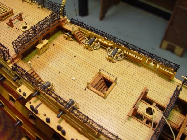
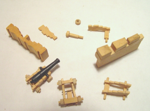
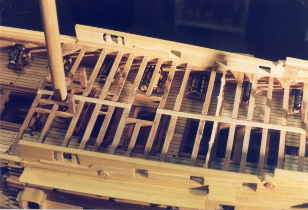
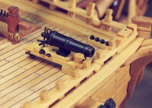
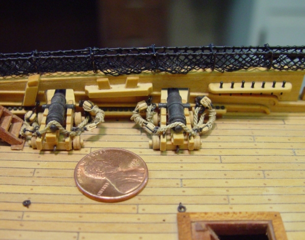
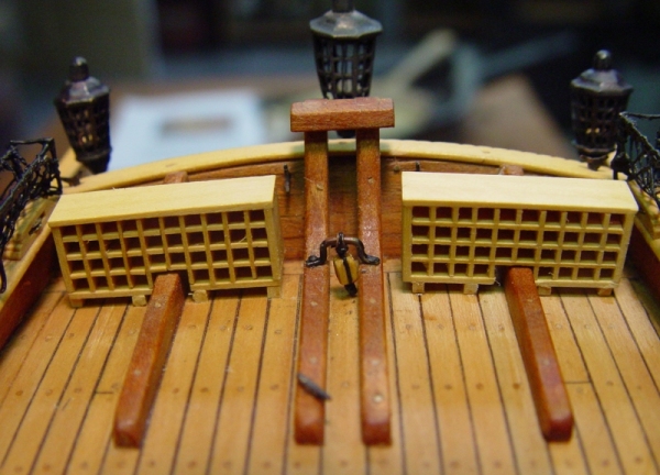
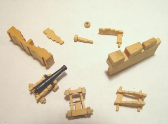
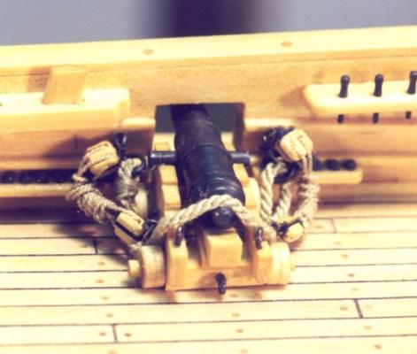
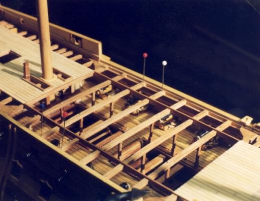
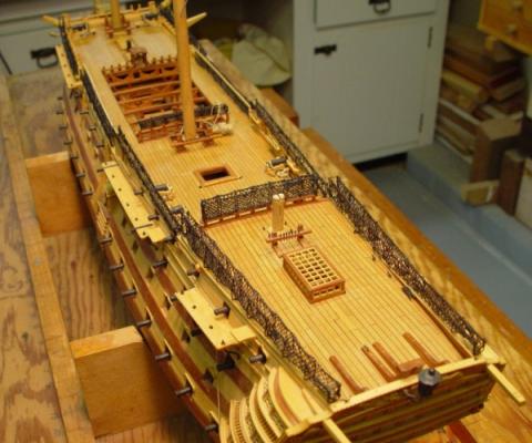
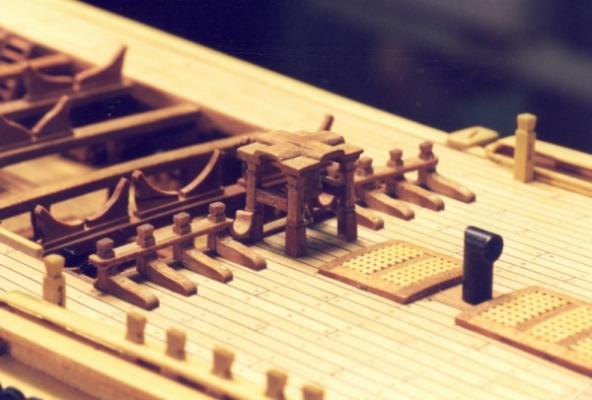
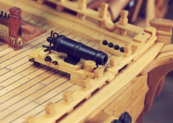
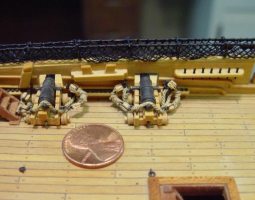
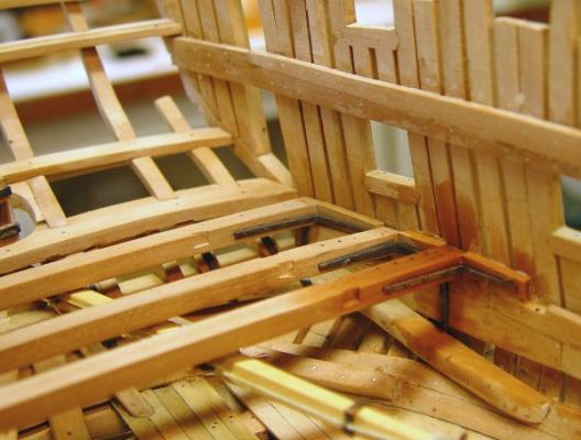
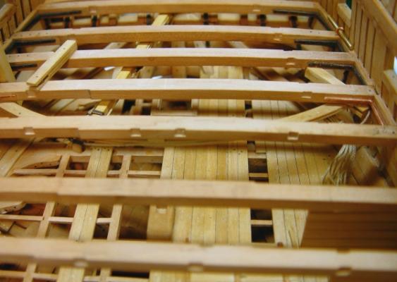
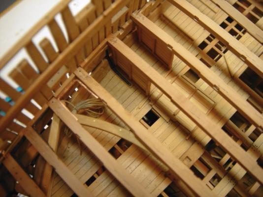
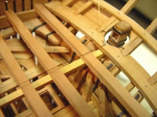
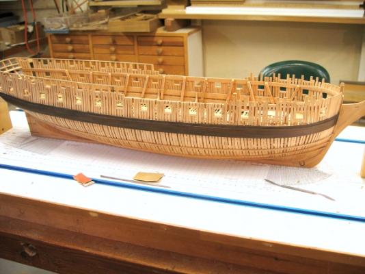
HMS Victory 1:96 Scratchbuild Project Part 8 – Deck Details 1 Posted to MSW 8/20/2010. In the next three parts I will describe, in general, the construction of the upper decks and their detailing, taking the narrative up to the completion of the hull. I have selected a few parts of this work to describe in some detail, but will not cover every point. As always, I welcome any questions. If there is some aspect where more detail is desired, let me know and I will be glad to describe it. The picture below shows the status of the model by the end of 1996. The exterior and most of the interior of the hull and the upper gun deck has been planked. The partition, which bars the way to the Admiral’s cabins is in place and framing of the quarter deck is about to begin. The extent of detailing on the upper deck was limited to what would be visible, so no more of the interior aft partitions or decoration was done beyond what is shown in this picture. Details visible through the hatches were modeled, for example the capstans, one of which is visible below the main hatch. The planking of the upper deck, the quarterdeck the poop deck and forecastle was done in European Boxwood using a four butt shift pattern. All the planks were glued and pegged with boxwood treenails. These were described in an earlier chapter. The 12” wide planks were ripped from 1/8” thick by about 1 ½” wide Boxwood strips using the Unimat circular saw. The black caulking between planks was simulated using black construction paper, which was glued to the strips before ripping them into planks, so that after ripping, each plank would have one edge with paper attached. This saved a lot of messy gluing of individual strips between planks. It also eliminated the need for scraping off excess glue and paper. Only the ends of the planks had to be fitted with paper strips. After gluing and tree nailing, the tops of the nails were cut off, the ends filed down flush and the decks scaped to a smooth finish with a 1/2” scraper. The picture below shows some of the finished decking, as well as some of the final deck detailing. However, quite a bit of work had to be done before getting to this stage. Back at the stage of the first picture, the next task, to be done before framing the quarterdeck, was the installation of the thirty long 12 pounder upper deck guns. On the finished model, some of these would be totally visible in the waist, and to some degree under the forecastle and quarterdeck, so these had to be well detailed. The gun carriages of the lower and middle decks were roughed out in maple and not rigged. The visible guns of the upper decks, all long or short 12 pounders, were modeled more completely and precisely, with full rigging. The carriages of these guns were made in boxwood, based on large-scale drawings. The barrels were described earlier. The picture below shows a collection of leftover or reject parts, which will help describe the carriage construction. The items in the above picture are laid out in a circular progression of the various steps. Starting at about ten o’clock is an odd shaped piece of boxwood. This has been milled to the shape of a carriage side, actually two sides facing away from each other. The sides were then ripped off of this on the circular saw and trimmed to size. The axles were made from rectangular pieces, which were drilled to accept the round parts which were inserted in each end. The wheels were turned to size, bored, scored around their circumference and parted off in the lathe. The larger assembly of wood at 3 o’clock is an assembly jig, into which the pieces were inserted for gluing, yielding the assembly at 4 oclock. Finally, an iron bar was inserted between the sides to hold the elevating wedge platform. Eyebolts were then added, the guns were pinned to the deck and rigged. Below is a picture of a finished quarterdeck short 12 pounder. The rigging of each gun includes the heavy breeching which restrains the recoil of the gun when fired. One end of this has an eye spliced around a large ringbolt in the side. The other end goes through another ringbolt on the other side of the gun, loops back on itself and is seized with lashing. Two training tackles, each consisting of a double and single block attached by hooks to eyebolts on the carriage and in the side. These were coiled up for storage. Ringbolts were also installed in the deck behind each gun. All the eyebolts and rings were made from brass wire. Rings were made by tightly wrapping brass wire around a rod the diameter of the ring. This coil of rings was then sawed through along the axis of the rod, producing many open rings. The ends of each of these were then silver soldered together to form a strong ring. All the brass parts were blackened chemically. I elected not to model the breeching rings on the pommels or the brackets over the trunnions. The scoring around the middle of the wheels was to simulate the two pieces of wood bolted together crosswise to make the wheels. The above picture also shows some of the very few purchased parts in the model – the belaying pins and the cannon balls. The pins were too short and a constant headache during rigging. The balls were perfectly sized and held in place with cyanoacrylate. With the upper deck guns in place, the quarterdeck framing could proceed. Some of this is shown below. It is semi authentic and certainly not completely represented. The upper deck guns are visible in this picture. Notice only those forward of the partition (and visible) are rigged. The first plank, the king plank, in the center of the deck has been laid. In the following picture the quarterdeck and forecastle planking has been installed from the center out to the inside line of the gangways. The waist beams have been temporarily setup to fit the notched gangway facings, which line the waist opening, and also to fit the turned posts, which support these beams. The beams themselves are 50 feet long and so are scarfed together with a long vertical scarf, which can just barely be made out in this picture. When all these parts fit correctly they were glued and treenailed into pace. All the remaining planking at this level was then installed. The next picture shows the model with all the decking and most of the deck detail finished. This picture shows the extent of the hammock netting. I will describe how these nettings were made in part 9. The remainder of this part consists of some pictures of other deck detail, which I will describe only briefly, but will be glad to discuss further if someone is interested in more detail. The above picture shows the belfry, the vent stack from the stove and low profile, rounded up coamings and gratings of the forecastle. On either side of the belfry is a row of timberheads with knees. These will carry buntlines, leechlines and braces for some of the forward sails. On the waist beams are the shaped supports for the ships boats. I will cover the modeling of these tiny, planked boats in a later chapter. All of this woodwork is cherry. The two boxwood posts at the rail on each side are kevels. There are several more about the deck. These two will take the fore topsail tyes through their sheaves and belay them around the timberhead top of the kevel. The starboard 68 pounder carronade is shown here before its breeching was installed. Four of its large diameter balls are in the shot garland along the catbeam. The timberheads along the forward fife rail have simulated sheaves and timberheads and will eventually be almost completely covered with the many lines that belay here. The topsail sheet bits, shown partly in the upper left corner have brass sheaves, which will take topsail sheets later. The above picture shows ringbolts in the deck for the guns, some of the shorter hammock netting, the large wooden staghorn for the port main sheet, and more of those purchased belaying pins. The penny was not part of the real ship. This last picture shows the flag lockers, which held the dozens of different signal flags. These were made, “egg crate style” by a method like that used for gratings which was discussed earlier. The stern lanterns are prominent in this view. I will discuss how these were made in part 9. Cheers, Ed Tosti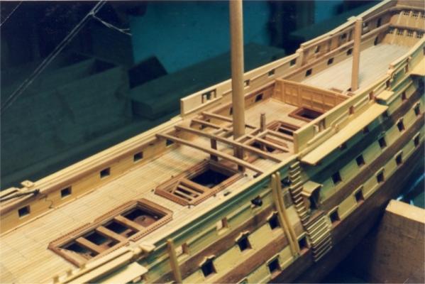


-
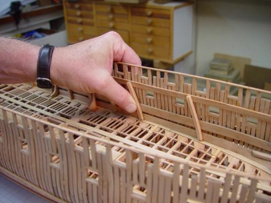
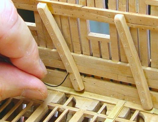
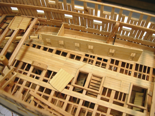
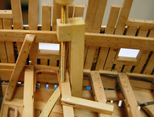
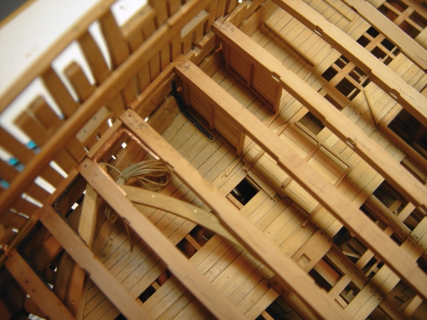
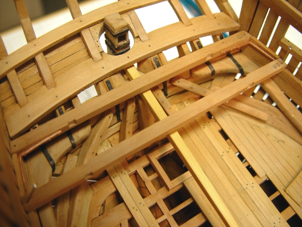
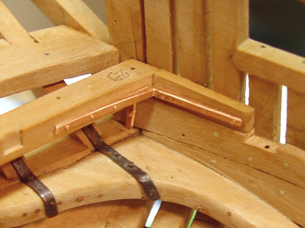
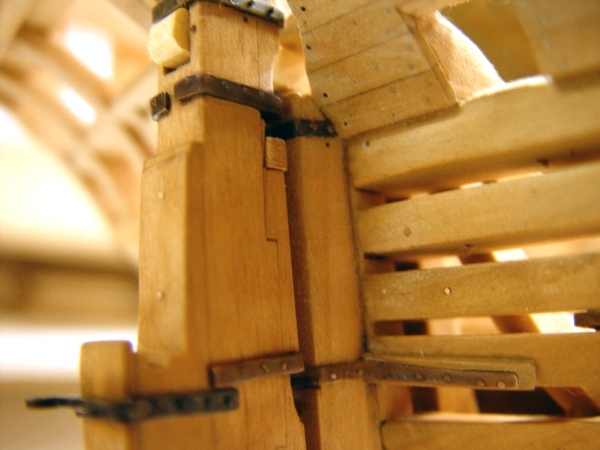
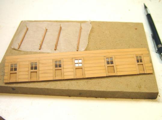
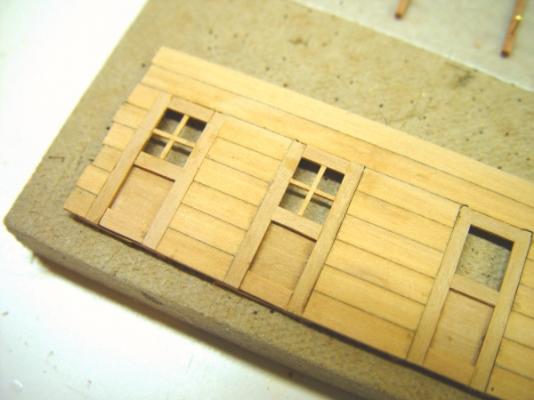
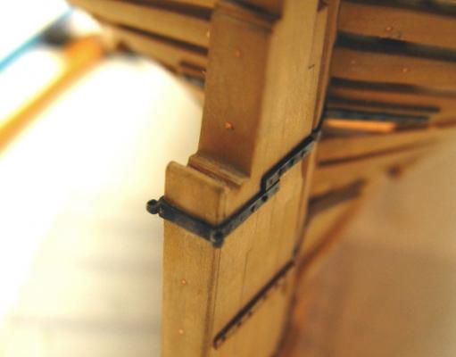
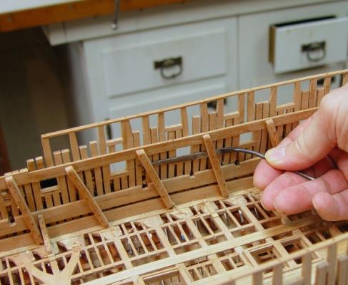
1:60 HMS Naiad 1797 Part 106 Officers Quarters/Tiller Sweep Posted 11/1/11 The next step in the puzzle was to fabricate the inside fore and aft wall of the officers’ cabins. This needed to be done at this time so the doors could be lined up with the opening in the baseboards on the deck before the beams would block access for this. The doors were made as simple paneled doors with glass lights. This was done in a simple way from the outside because the insides will be completely enclosed by the decking on this side and not visible. The next picture shows this simple construction. The stanchions for the wall were first laid out and pinned on the grey Homasote board and the planking was glued to them over the full length. The doorways were then cut out on the circular saw. With the bottom panels glued into the openings, the side frames and stretchers were glued in place. The window mullions were then fabricated as tees from notched strips, cut to size and glued in. The mullions were then bearded slightly on the outside to eliminate the clunky square appearance seen in the above picture. Transparency film was then cut to size and fixed to the back of the door with holding strips. The next picture shows the wall in position so the notches for the beams can be marked. The next picture shows the wall with notched for the beams. These cuts are a bit loose so the wall can be slipped into place after all the beams and internal partitions are installed. This is necessary because access is needed to install the knee bolts for each beam and this could not be done with the wall in place. The door hardware has also been installed in this picture. The doors get a bit more elegant at each deck – simple planked doors on the lower, simple paneled doors at this level and hopefully more ornate fancier panels on the next deck – the Captains quarters. Unfortunately the lower deck doors are mostly now out of sight. Beam 25, which supports the center of the sweep, was then installed along with its iron knees. In the next picture the sweep is being permanently fixed into place. The next picture shows a closer view of this. The port side of the tiller is threaded up and the near side still has a remnant of the rope that was originally installed on that side. That will be removed when the final attachments are made later. There is a small pinhole visible in the top of the tiller just aft of the sweep. This was used to align the sweep to the tiller arc so when the gooseneck is installed it will not bind when the tiller is moved. The last picture shows this assembly from forward. The scarph bolts are also visible in this picture. These have now been installed in all the made beams. The deep notches in the deck clamp visible in this picture are not the beam notches, which are very much shallower. These are the cutouts for the ventilation scuttles – one in each cabin on each side and six more for the other 250 or so crew. Ed

-
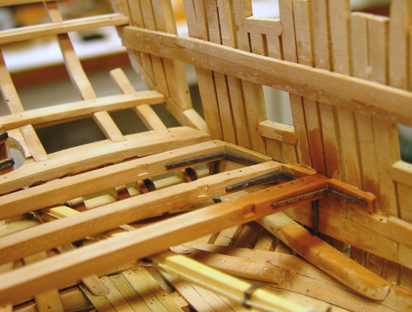
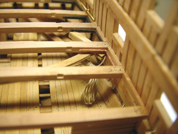
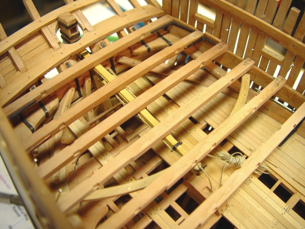
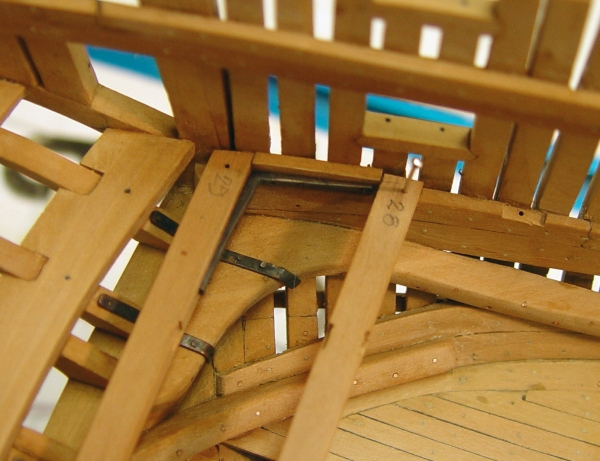
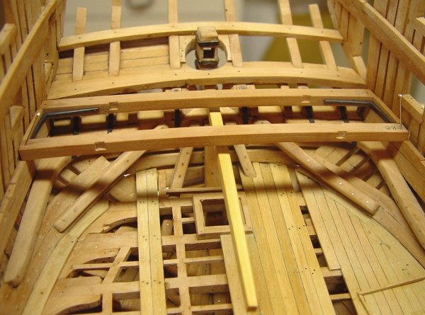
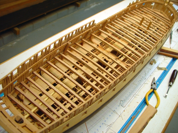
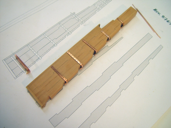
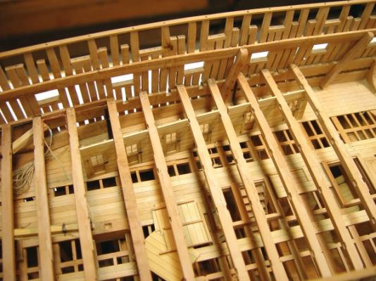
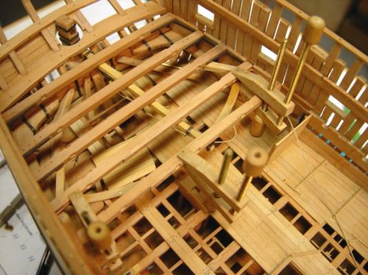
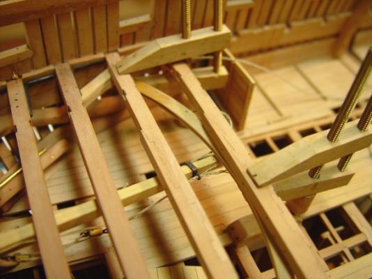
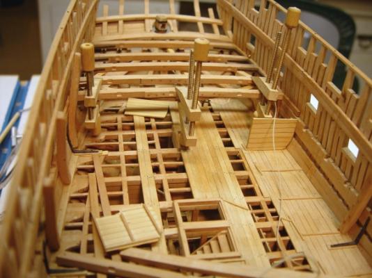
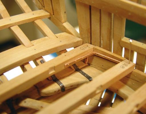
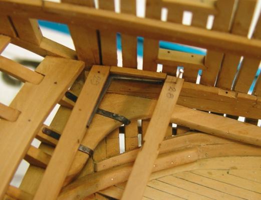
1:60 HMS Naiad 1797 Part 105 Aft Upper Deck Beams Posted 10/28/11 In Part 103 I discussed the way the beams with iron knees were being fabricated and the sequence for installing them and in 104 discussed the tiller sweep. The installation of the beams that will support the tiller sweep and the associated sheaves, in and around the officers cabin partitions, turned out to be an interesting puzzle, but first some improvements in the beam and iron knee process. The first picture shows a step in the slightly modified process for attaching the iron knees to the beams. Initially the bolts were basically “nailed” into the beam in predrilled undersized holes and in the nailing process a head would be formed and peened over on the copper bolt. The new process is somewhat more authentic. The copper wire is forced all the way through the beam, then cut flush on the back side and cut somewhat higher above the surface of the knee. The picture was taken just before cutting off the excess. The beam was then laid on an anvil and the bolt hammered to form a head on both ends, leaving (usually) a very tight bolt. The next picture shows a pre fabricated beam assembly. I believe this is beam 27 on the drawing. The next picture shows this beam glued in and the bolts installed through the filling pieces into the frames. These are still being done like nails. The wood is wet from washing off of the sulfur blackening solution. The next picture shows a U-shaped lodging knee, necessitated by the presence of the rider forward of beam 25, leaving no room for a lodging knee on that side. This knee is bolted to beam 26 in the picture, but bolting to beam 25 to the left will have to be done in place, but first beam 25 needs its hanging knees. The picture also shows one of the sheave assemblies that will be installed at the ends of the sweep under beams 26 and 27, the middle two in this picture. The sweep is also clamped temporarily in place in this picture. The next picture shows the present state of construction with the aftermost 4 beams installed. In the picture the end sheave assembly has also been installed. The sweep is still only clamped. The sheave bracket needed to be precisely located so the rope would run smoothly into the groove in the sweep. The officers’ cabins further complicate this work and need to be fitted up in concert with the sweep so the rope will not be fouled by the aftermost partition. This required laying out the run of the rope to the location of the sheaves ahead of the mizzenmast that will lead the rope up to the wheel. This all required a lot of finicky checking and some adjustment to the partition location. The next picture shows the sheave with the rope led into the sweep. I left the end of the sheave bracket open to facilitate feeding the rope through. This side was threaded up first because all this will be covered with decking. The other undecked side will be threaded up after the wheel is installed and the rope will be made off to the other side of the tiller. The next picture is another view. The rope is comfortably in the groove and barely visible. The last picture is an overhead view showing the U-shaped knee on the port side. The aftermost partition was removed for this picture and is lying on the deck. The next two are in position. They fit right under the beams to one side of the iron hangers yet to be installed. The sheave brackets leading the rope up to the wheel, will be fit between beams 24 and 25 and will need to be positioned around the space for the mizzen mast. Whew! This has been a very interesting and at times frustrating bit of assembly, but I think it is going to work out. Ed


-
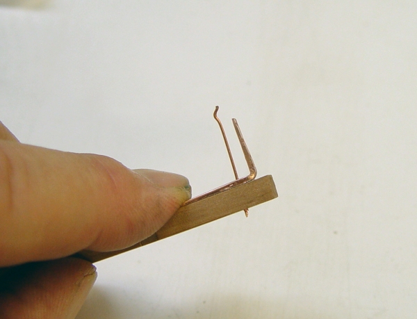
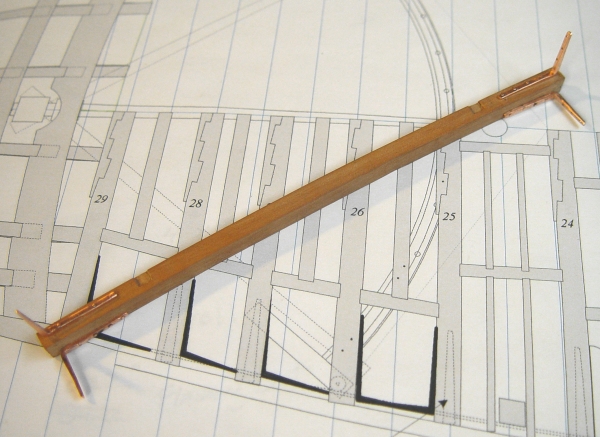
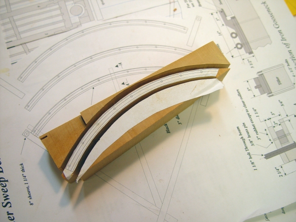
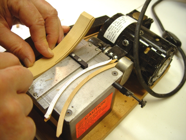
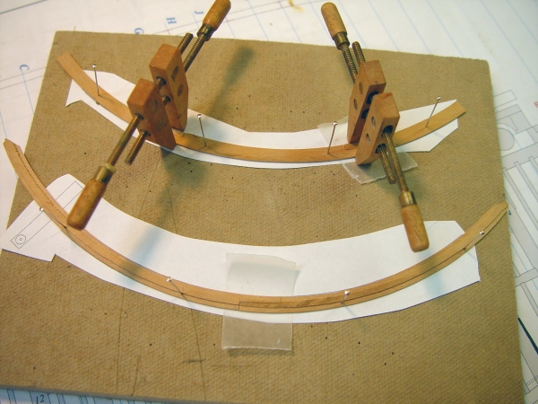
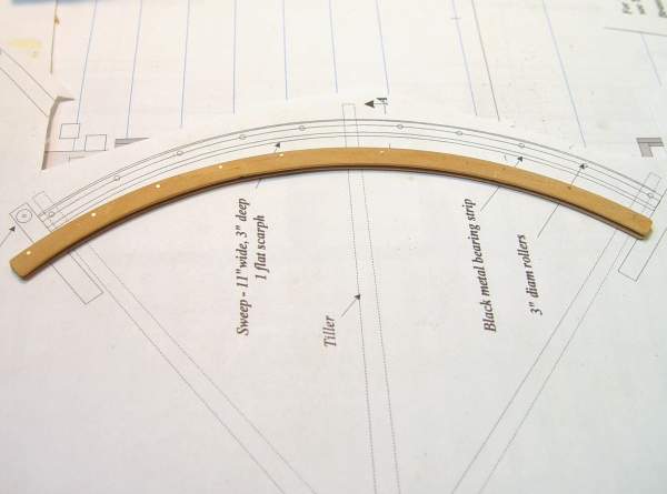
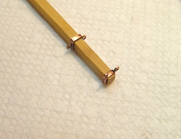
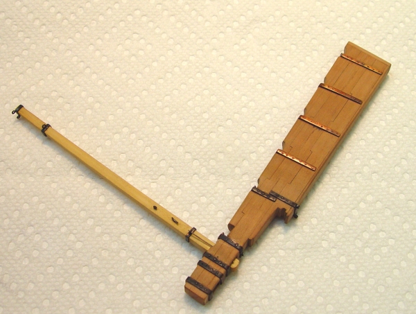
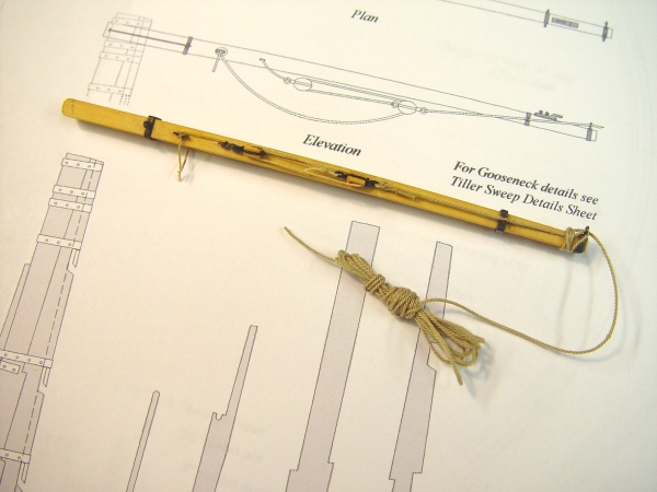
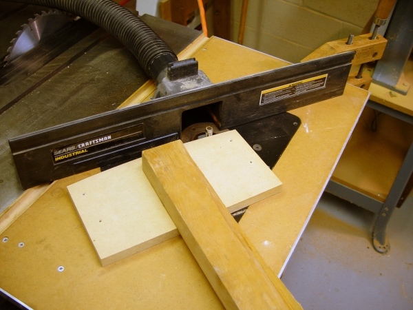
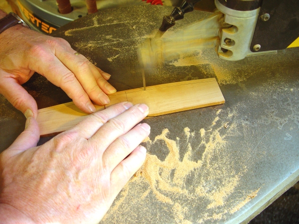
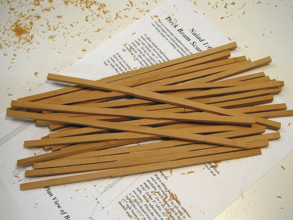
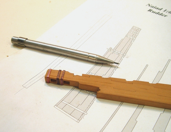
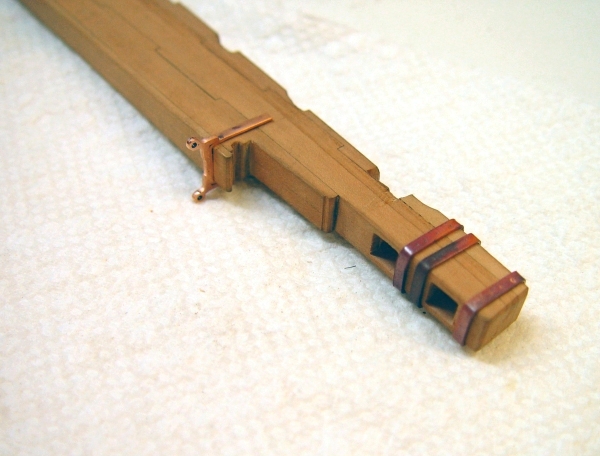
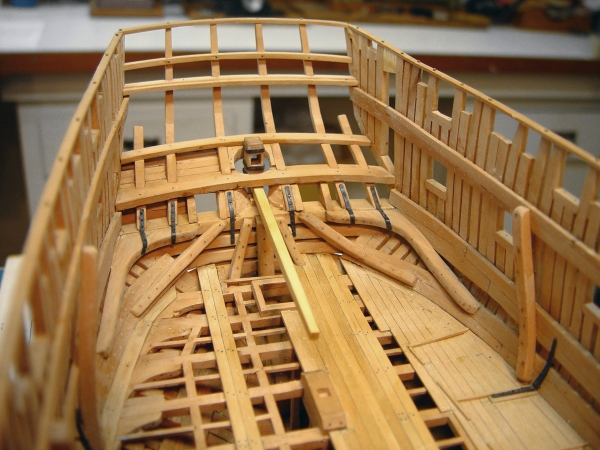
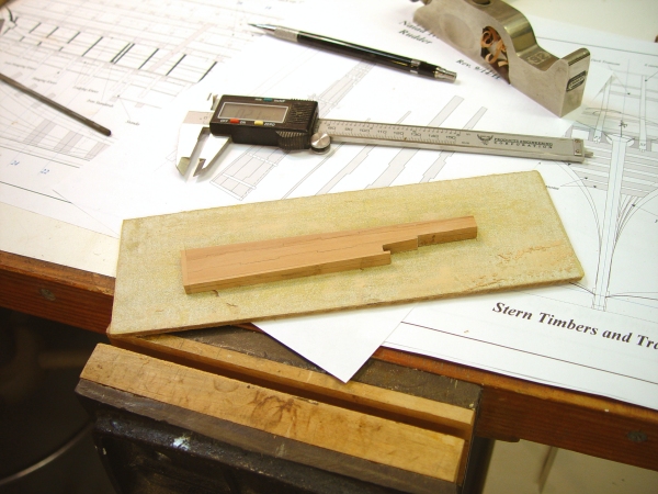
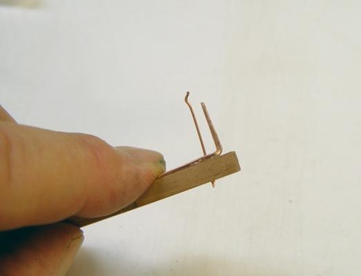
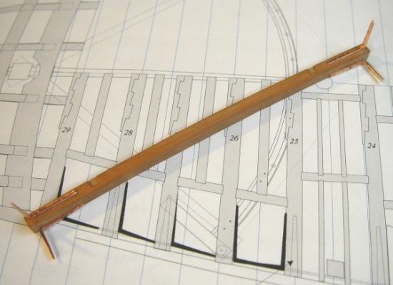
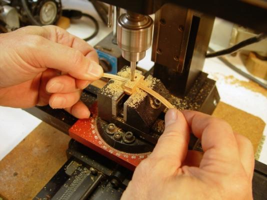
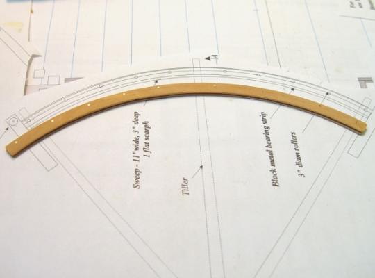
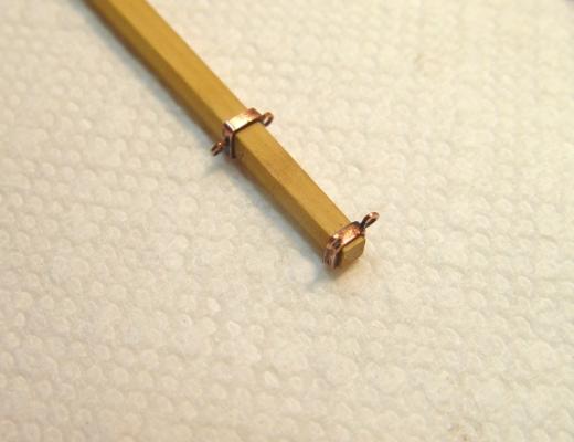
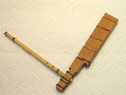
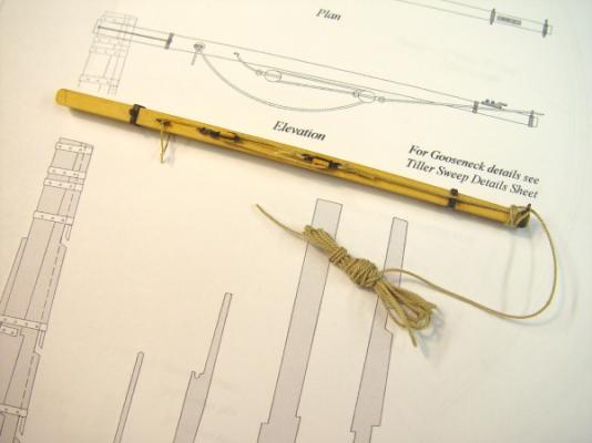
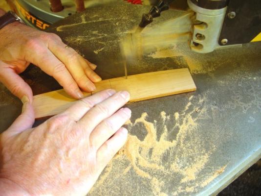
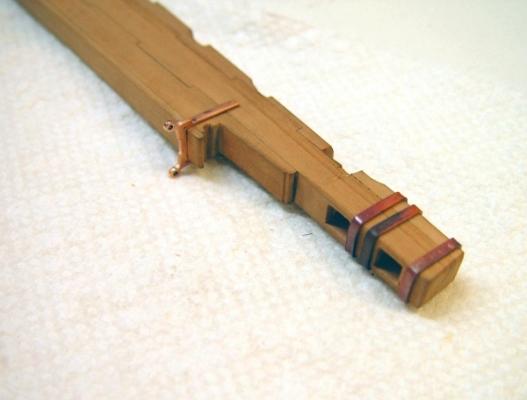
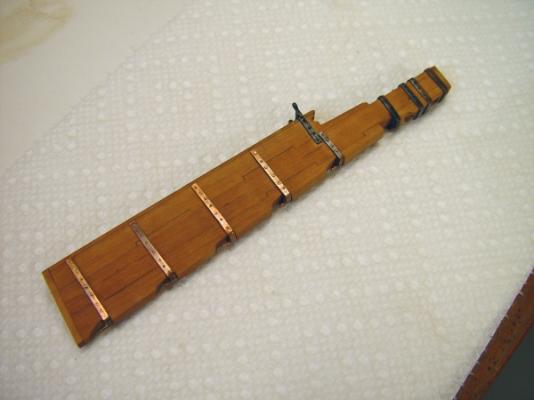
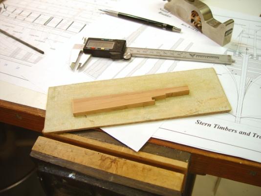
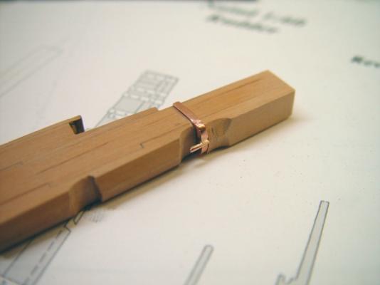
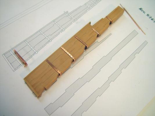
1:60 HMS Naiad 1797 Part 104 – Tiller and Sweep Posted 10/24/11 Before installing the upper deck beams aft of the mizzen mast, the tiller and its sweep mechanism needed to be made so all this could be installed together in some way – as yet undetermined. The first picture shows the curve of the sweep cut out of a thick Castello block. This was then sanded to the pattern on the disk sander and curved strips to make the sweep were sliced off on the circular saw as shown below. The sweep is made in two layers, the bottom from two pieces and the top from three to offset the scarped joints. The bottom part is thicker and is rabbeted on the inner and outer edges to accommodate the gooseneck guide on the inside edge and the rope to the wheel on its outer edge. The rabbets were cut on the milling machine with the aid of a guide as shown in the next picture. The two halves were then assembled on the patterns as shown below. The next picture shows the finished sweep. It is quite simplified from the original. The brass pins are larger than the prototype pins for the 3” wooden wheels between the layers on the aft side. On the model the pins will serve as rollers. The tiller was made from Euro Boxwood and fitted with copper fittings. The picture below shows the end fittings before blackening. The next picture shows the tiller/rudder assembly. The tiller is fastened to the rudder by two long bolts which, allow it to flex up and down. This is required because of the angle of the tiller relative to the axis of rotation of the rudder. The parts have all been blackened in this picture. The next picture shows the rigging of the tiller. Two single blocks with tackle were fitted on each side so the main tiller rope could be tensioned. The larger tiller rope is attached to one side only in this picture and wrapped temporarily around the end of the tiller.. Later when the wheel is installed the excess rope coiled up in this picture will be threaded up to the wheel and back through the sweep to be attached to the block and tackle on the opposite side. All this rigging was made from parts and rope left over from the Victory model. The last picture shows the tiller and sweep installed temporarily under the aft upper deck beams, which are also only set temporarily. There are two mounted sheaves yet to be made which will be placed at the ends of the sweep to guide the rope from the wheel into the sweep track at the ends. These will be made and fitted along with their supporting beams. Ed


-
Thank you for these comments. They are well appreciated as always. Wacko, its easy to make a little hammer. Its the little hand that is difficult. Martin, I really am looking forward to posting the new progress. Getting those postings up has been one of the drivers that has kept my nose to the grindstone. Pat, I tried to mechanize the fabrication of beams as much as possible to remove the skill factor from the finished product and to save time. So, cutting the tables in the scarfed joints - so they will actually fit together - is left almost completely in the hands of the calibration wheels on the mill. The beam curvature is set by the jig with the round up built into its face. The less importent curve on the bottom of the beam is accurately sanded based on the top curve using the thickness sander. The scroll saw cut of the bottom curve is just cut close enough to the line to allow the thickness sander to finish the job on all the beams at one setting. In any case, the curve of the lower face, if done by hand in the absence of a thickness sander, is not that critical - or that visible. The top face is the one to worry about, since it has to be fair for the deck planking.
-
Thank you for all these comments and for the interest in the book. As far as the value of the book to builders with limited experience, I can only say that my goal was to write it in a way that does not assume a lot of knowledge of the subject or of scratchbuilding methods, while at the same time describing the construction of a fairly complex model. Readers will have to judge how well this was achieved. Hopefully experienced builders will be patient with some content that they already understand. Volume II is well along, with only the last 4 chapters to write. Of course, there is a lot of editing and checking to do - and there is the production process. Again, thanks for the interest in the book. Ed
-
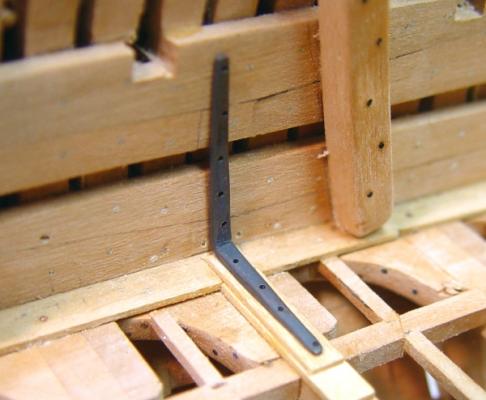
1:60 HMS Naiad 1797 Part 103 – Beam #29 Posted 10/18/11 I knew I was letting myself in for a lot of work and some uncharted territory when I decided to model ironwork knees on the upper deck beams. There are two basic types with a number of variants. First there are ordinary iron knees of the type shown previously where they were used for the lower deck standards in the officers’ cabins. There will also be Roberts plate knees – I hope. Making the ordinary iron knees is fairly straightforward. They are formed from copper strip cut to size on a circular saw, then bent, tapered, drilled for bolts and polished. The picture below shows two of these on the aftermost beam - #29. There are also two iron hanging knees on this beam, but are not visible in this picture. Beam #29, the first upper deck beam to be installed, was a test case for the installation sequence, which is a bit complicated, mostly due to the bolting issues. The next picture shows a closer view of the iron knees after the first series of steps. All four knees are permanently nailed to the beam at this stage, but the beam is still loose in its position on the clamps. The filling piece behind the lodging knee is temporarily in place so the knee’s bolt holes can be marked on it. It was then removed and the holes drilled for the bolts. When possible these holes will be drilled in place so the bolts can be directed through the frames. These holes are smaller than those in the knees. The holes for the hanging knees were also marked on the clamp and drilled with the beam removed. The next picture shows the full beam assembly in position. After drilling the filling pieces were glued in and the beam was glued to the clamps. Bolts of drawn 22 gauge copper wire were then pushed through the knees with pliers as far as they would go. The bolt was then clipped off just above the surface of the knee and tapped with a hammer to drive it tight, expand it in the hole in the knee and peen the top. The tiller sweep is shown in this picture lying on the top of the beams. It will be secured under these beams after they are installed. I will discuss making this sweep in the next part. The next picture shows the port side knees at this stage. All this work was done before blackening because all these operations will scratch the metal and leave bare spots. The next picture was taken after blackening the copper with liver of sulfur solution in place. The filling piece will be trimmed back to be flush with the tops of the beams. And the next picture shows the entire beam permanently installed. This sequence seems to work effectively so it will be used for all the beams of this type, working from the ends toward midship. I may need to make a small hammer to drive the bolts on the hanging knees under the beams. Copper is being used for these parts because it can be blackened in place without staining the wood. It is easy to cut, shape and polish but because it is soft it can be hard on the #71 drill bits, which I am now buying by the dozen. Cheers, Ed


-
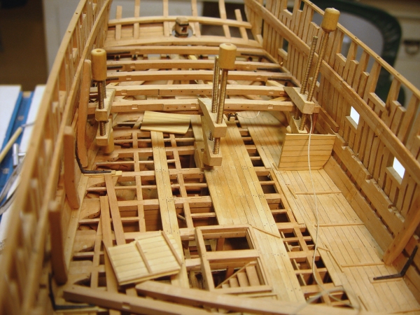
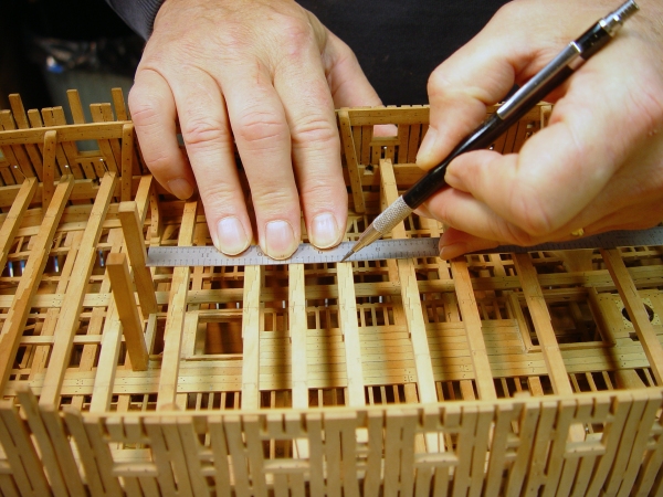
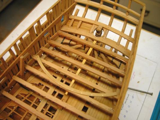
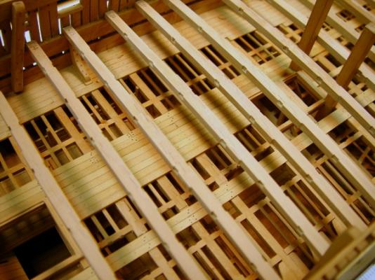
1:60 HMS Naiad 1797 Part 102 – Making Upper Deck Beams 2 Posted 10/18/11 The next step after making the rounded up beams, was to set them on the clamps. The first picture shows this in progress. To get the beams into position, some of the top riders had to be removed on one side. I decided to remove these from the port side, since that side will be planked internally and the riders, in addition to blocking the setting of the beams, would also have made the planking more of a chore. In this picture some are removed. The rest will also be coming out. Shallow notches were cut into the clamps to seat the beams at their ends. When all the beams were set and pinned into position a wire was stretched tightly along the centerline of the deck and each beam marked in its center. The aft end of this wire is shown in the next picture. The rudder and tiller are still only temporarily positioned in this picture. After marking the centerline on the beams the wire was removed. Next the seats for the carlings were cut into all the beams. The next picture shows the locations of the carlings being marked on each side of each beam. There are about 100 ordinary carlings on this deck, requiring twice that many joints to be cut. Marking one side of each seat with the beams in position using a straightedge helps assure the lines of the carlings will be straight. There are three tiers in the midship area diminishing to two at the ends. The beams were then individually removed and the seats marked out and cut into each one with a small chisel. The next picture shows one of these after cutting the joints – and the chisel. Only seats for the ordinary carlings were cut at this stage. There are a number of larger special purpose carlings that will be cut next, but it seemed easier to focus on just one size first. After cutting the joints in each beam it was given a sanding with 220 grit paper for smoothing to remove all the pencil marks. Each was then renumbered and returned to its position. The last two pictures show the beams in place with the carling scores cut. The lodging and hanging knees for this deck will feature a lot of ironwork, a combination of plain iron knees such as the few lower deck standards installed earlier, and Roberts plate knees. Use of iron was becoming more commonplace by this period. There will be a number of wooden knees as well. The installation sequence necessary to get all these knees in and bolted is still being worked out. In general the method followed for the lower deck beams, of pre installing the knees before setting the beams, will be used. The last picture shows the full set of beams set in place. The next step will be to remove each beam, cut the remaining special carling seats and install the bolts through the scarphed joints. Ed

-
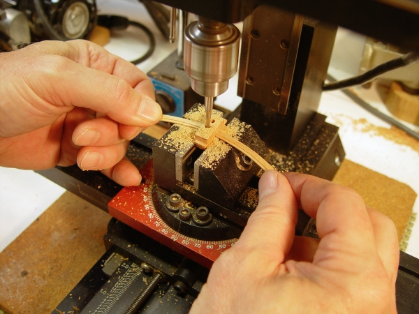
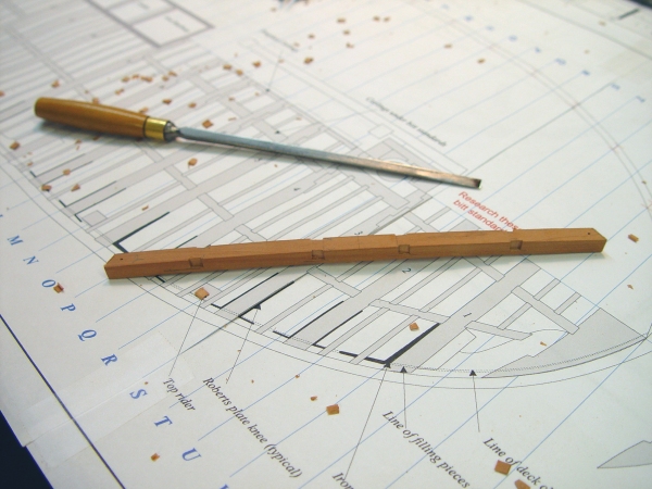
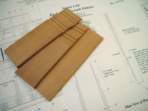
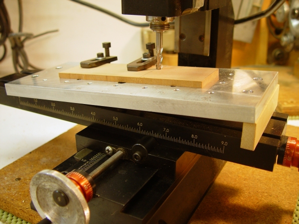
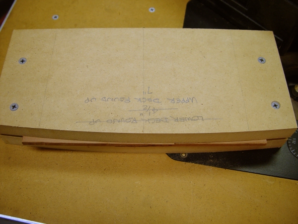
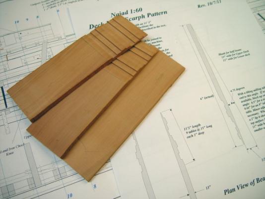
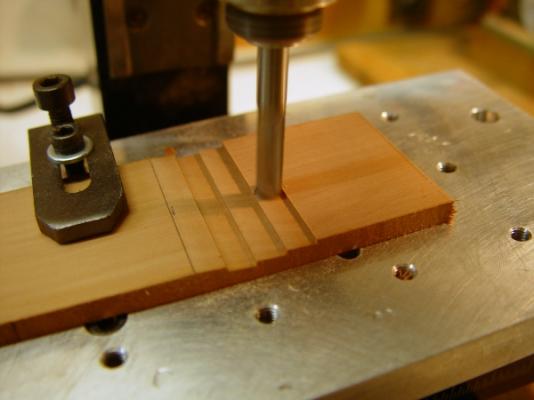
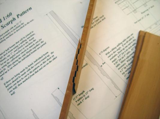
1:60 HMS Naiad 1797 Part 101 – Making Upper Deck Beams Posted 10/6/11 At the end of the last part I was planning on doing the tiller and sweep next, but before any of this can be installed the upper deck beams need to be made, detailed and set up in place so I decided instead to tackle the large job of making and detailing the upper deck beams. But before getting into that I did a bit of rework on the rudder spectacle plate to bring it to a more typical shape. This is shown in the first picture. The original version was taken from White’s AOS book on Diana and had the eyes on extended arms. This arrangement is more conventional. So, on to the deck beams. Like the lower deck beams, these were made in two pieces with a long vertical tabled scarf joining them at the center. The next picture shows the tables cut into 2” wide blanks surfaced to the width of the beams, 13 inches. When these pieces are joined, the beams will be rounded up and cut from these. The tables are each 15 inches long and 3 inches deep. Nine tables make up the 11’3” length of the joint. It is a slightly simplified arrangement to facilitate the machining. The next picture shows the milling machine set up for cutting the joint configuration. The angle of the scarph is roughly 5 degrees (actually 4.75) so for a milling table length, in this case, of 10 inches, one end needs to be elevated 0.8 inches (actually .83). That was done using the wood block cut to that size. This setup is very rigid. The angle was tested first by traversing the cutter. It leaves a 2” lip at the end and just skims the surface at the beginning of the joint as shown in the picture. The next picture shows a joint being cut. The 15” table length allows a ¼” cutter to be used – not a coincidence. After each cut the position of the cutter is reset using the mill calibration wheels giving very accurate dimensioning. The next picture shows the fit up of two of these wide pieces. The initial fit is very tight so the sides of the tables are given a few passes with a file so the pieces slide easily together and leave enough clearance for the glue joint to show. When the pieces are glued up the next step was to cut the round up on one edge. This was done using the curved jig shown below. The blank was clamped as shown into the jig and the surface rounded off using an edge trimmer in the router. The bearing on this bit rides on the pattern and the cutter duplicates the curve. This is the same jig used for the lower deck beams but has been re shaped to the larger round up of the upper deck. The next picture shows how this jig was shaped – also using the router table. I have a pattern for the round up, but I do not trust my eyesight to shape this manually, especially since it will be used for 25 plus beams. Also the pattern the pattern from the drawing is only the length of the beam and I like to have excess in the rough beam length. The picture above shows one half of the jig attached to a length of 2X4, which acts as a radius arm. The other end is pinned at the radius of curvature of the round up, which is calculated for the 7” round up to be 52 real inches (263 scale feet). Moving the router bit into range allows this curvature to be cut very accurately. The second half of the jig is then attached to the first and its shape duplicated. When the curve was cut on the edge of the blank the first beam thickness was marked and the beam cut off on the scroll saw, freehand, as shown below. After parting off, the underside of the beam was sanded to the final depth of 11 inches using the thickness sander. The next picture shows the result of two afternoons of work. This process produces identical, rounded up, scarphed beams that can then be cut to length and fit into position. There is still a lot of work to be done on these – bolting, fitting of the knees, etc. The next step will be to finish the tops of the clamps, which were installed earlier. Ed


-
Daniel, thank you so much for this comment. Reposting the log is fairly easy, since I saved all the text and the pictures for each in separarte folders. It only requires editing some text formats, reloading the pictures and placing them in the text. Doing more than a few at a time is, however, tedious. I am looking forward to finishing the task soon and posting the final work on the model, which is almost complete. Thanks, again. Ed
-
Thanks, Martin. It won't be long Maury. Cheers, Ed
-
OK. A milestone. The first 100 parts reposted. 77 to go and we can get back to real time. Ed
-
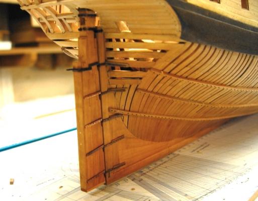
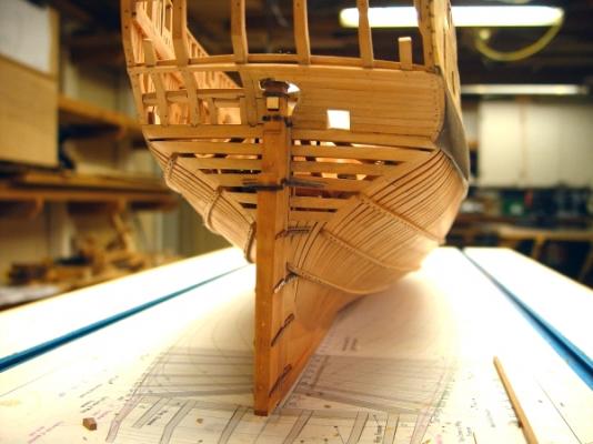
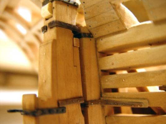
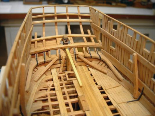
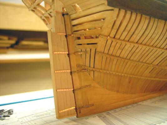
1:60 HMS Naiad 1797 Part 100 – The Rudder 2 Posted 10/6/11 In the last part the pintles had been fabricated and test fit. The next picture shows additional work done on the rudder. Three iron hoops at the top have been made and fit to the head of the rudder right after they were silver soldered and pickled in vinegar – hence the color. The hances were also formed and the notch cut for the wood chock under the top pintle to keep the rudder from being unseated. The next picture shows the fabricated spectacle plate for the chain preventers. All the iron and bronze work was made in copper as described earlier. The next picture shows the finished rudder. The fittings above the waterline were iron and below “mixt metal”- bronze. All the parts were colored with liver of sulfur solution– basically potassium sulfide. The lower fittings were cleaned off with water right after the application of the solution to give them just a brown “bronzy” patina. The parts at the top were treated until black, with the same solution strength but allowing more time. I decided to try something new with this. I mentioned that the sulfur solution does not effect the wood, so rather than coloring the parts before installing, all the coloring was done after the polished copper parts were fastened on with the copper bolts. After installing the bolts and buffing them with a fine Scotchbrite pad they were washed off with acetone. When dry the parts were brushed with the sulfur solution and when the desired color was reached the solution was washed off with water. This allowed the fittings and the bolts to get to the same color and avoided bright spots and scratches from the installation and bolting. This worked quite well. It is much easier to do the nailing before the nails are treated. The bolts were made from a length drawn copper wire, clipped sharp at the end, pushed all the way into a tight hole with pliers, clipped off just above the surface then peened down with a hammer The next picture shows the rudder in place. As mentioned earlier, the rudder has been adjusted downward so the bottom is now at the height of the top of the false keel. The next picture shows the rudder from directly astern. The tiller has been inserted in this picture. That small piece of wood in the lower left part of the picture is the retaining chock. The next picture shows a close up view with this chock inserted below the top pintle. The tiller is held in place with two long fore and aft bolts through the rudder on either side of the tiller mortise. The head of one can be seen in this picture. The bolts are long and fasten to a fitting several feet forward on the tiller. This allowed the tiller to rock up and down as it swung to either side so it would stay engaged on the sweep without binding. These bolts will be installed later when the tiller is permanently fixed. Holes have been drilled in the fore side of the rudder where these will be inserted. The next picture shows the tiller on the interior. Note the second square tiller hole above the upper deck transom. This was an emergency provision, which would allow a second tiller to be fitted if needed. The tiller will be just below the upper deck beams and its forward end will be vertically restrained in a track-like “sweep” – an arc of wood bolted to the bottom of the beams. This is a fairly complicated device and I will not attempt to describe it until later when it is made. The sweep is horizontal. Given that the axis of rotation of the rudder is not vertical and that the tiller will be angled down at its forward end to match the sheer of the deck, it is easy to see why a joint at the rudder that allows up and down rocking is necessary. If this is not clear, it will be later when the sweep is installed. The next steps will be to make and fit the tiller hardware and permanently install it and the rudder before going on the upper deck beams, Ed

-
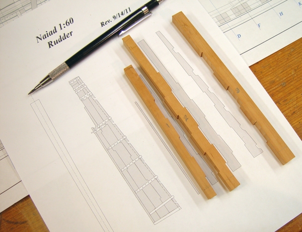
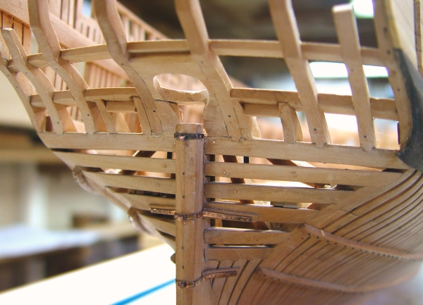
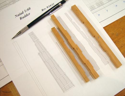
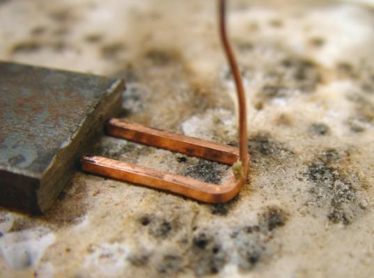
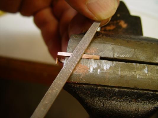
1:60 HMS Naiad 1797 Part 99 – The Rudder 1 Posted 10/2/11 It has been a while since the last update. We took some vacation time, but the work has also been time consuming for what appears to be small progress. In the last part the framing and planking of the lower counter was completed in preparation for installation of the rudder. The plan is to install this and its operating mechanism concurrently with the installation of the upper deck beams. I had not done the drafting needed for all this, so some time was taken for that. The first picture shows the main timbers of the rudder cut out and their joints machined. The joints were cut on the milling machine, straightforward work except that the joints need to be placed to avoid having some pieces too thin, especially around the cut outs for the pintles. Three pieces were used for the main section and are shown above. The two to the left are parallel to the aft edge and the one to the right will be tapered on its fore edge. There is also a thin strip on the aft face and a bottom piece. The next picture shows the rudder after its forward face was bearded back to clear its rotation and after tapering. Before bearding the rudder was sanded down to its maximum breadth on the thickness sander. The bearding of the front face was then done. Both the post and the rudder have bearded edges, cut about 6 inches or so back on the side faces to allow the rudder rotation. With this done the rudder could be tapered. This was done by sanding, initially on a belt sander and then as shown in the above picture on flat panel covered with 120 to 220 grit paper. The next picture shows the top pintle being fitted. There are six of these of increasing length going down. There were originally made of “mixt metal”, a bronze type of alloy. I used copper as I have done for all the copper bearing fittings. This picture also shows the transition from the bearded section to the squared off top. The hances on the aft face will be shaped later. The next pictures show the way the pintles fittings were fabricated. The first shows a rough piece set up for silver soldering the pintle to the bracket. The square U-shaped section shown in the picture was cut from a sheet on the circular saw using a thin slotting cutter blade. It was then bent to fit tightly around the rudder and cut roughly to length. A slot to fit the pintle itself was then filed in the end and a copper rod of the correct size fit into the slot. In this picture the rod is forced down into the refractory surface to hold it in place. The bracket is held in place with the piece of steel barstock. A small amount of solder/flux paste has been applied at the joint and all that is needed now is the torch. In the next picture the bracket is being filed to shape. As each piece was finished it was fit to the rudder and the rudder fit into the gudgeons, one at a time, so that when all six were made they would fit accurately into their mating fittings and allow smooth rotation of the rudder. They were then marked for drilling the bolt holes. The next picture shows all the pintle brackets made and temporarily fit to the rudder. After drilling with a number 74 drill, they were be-burred, filed smooth and polished. The next picture shows a fit up of the rudder to the post with all the brackets. These still need minor adjustment and it is obvious in this picture that they are not yet aligned. When this is done they will all be perpendicular to the forward face of the rudder. As these were being fit the opening of the helm port was adjusted to give full range of rudder movement. In this picture the stern post is showing the effects of my dirty hands from the metalworking. This will of course be cleaned up. There is additional metalwork to be made and installed, the spectacle plate, one or two reinforcing straps and a number of straps around the top. There are also the two tiller holes to be cut. Those are the next chores on the agenda. When all these pieces are made and fitted, the rudder will be polished up and all these fittings chemically darkened and bolted on. Ed
-
Thanks, Remco. Problem is, we don't have too many old castle gardens over here in the new world - or wood instrument makers for that matter. It would be nice to find a supplier, however. Ed
-
Egen, you are correct. There is quite a bit of preparation needed for a project like this. Good luck with the build. Ed
-
Salvatore, The 6 1/2" dimension given on page 45 appears to be a typographic error. The rising wood, or deadwood should be 8 1/2" thick and 18 1/2" wide as is shown on the drawings and on the patterns for the frames. Sorry about the error. Generally, I would rely on the drawings in case of any discrepancy. Drawing 4 and specifically the Drawing Notes sheet for that drawing on the CD are correct. I for scantling dimensions like this one, the notes sheets are the best source. Thank you for bringing this to my attention. In spite of extensive checking I expect other discrepancies may arise as people start building. I will be happy to resolve any any of these when they arise. Ed
-
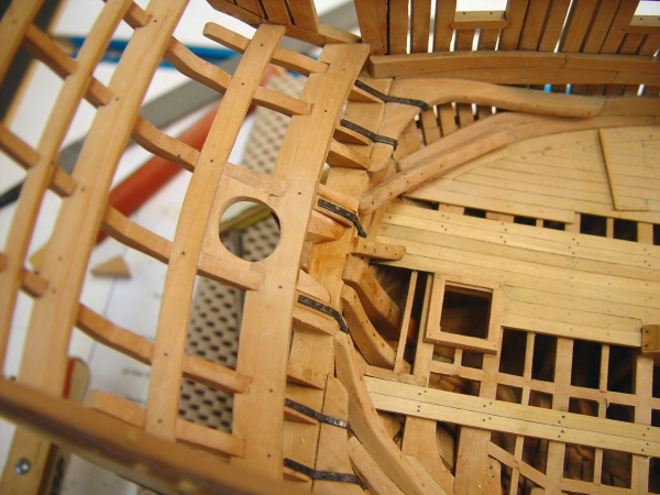
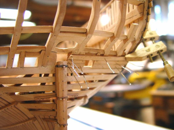
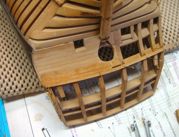
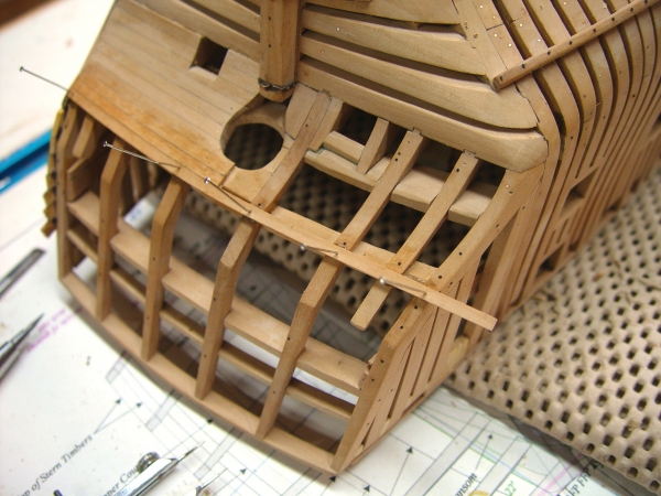
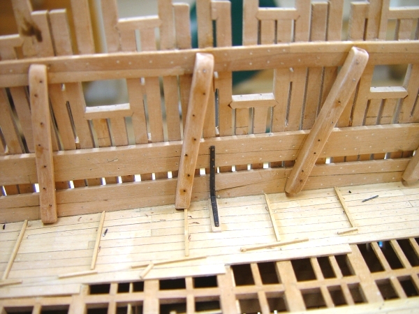
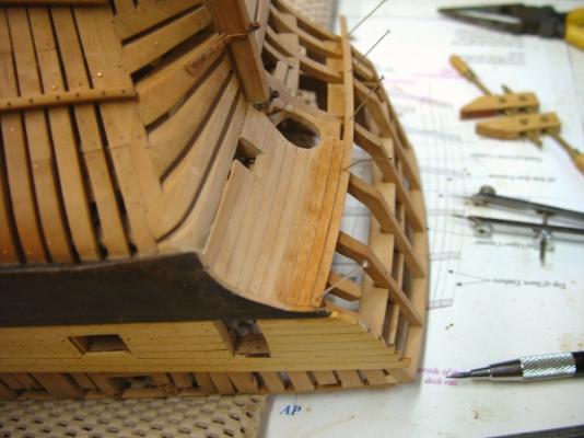
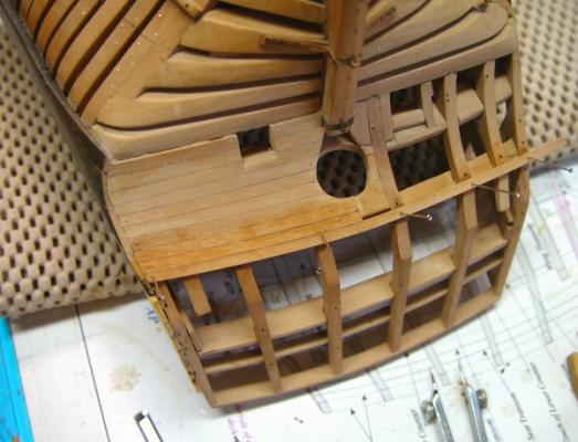
1:60 HMS Naiad 1797 Part 98 – The Lower Counter Posted 9/13/11 I doubt this part will generate as much interest as part 97 on the lid stops, but who knows. Before getting to the lower counter framing and planking I finished up a couple of loose ends on the lower deck. The first picture shows one of the iron standard knees in the area of the officers cabins, before bolting. The knee is copper blackened with liver of sulfur solution. It rests on a “shole” on top of the decking, which is curved on its underside to fit the waterway. The large timber to the right is a top rider and the notch to the left is a roughed opening for a ventilation scuttle. These were covered earlier. The next picture shows the first steps in framing the lower counter and also the starboard straps on the lower ends of the counter timbers – also installed at this time. First the sides of the ports were framed. The helm port opening between the upper deck transom and the seat transom was filled in with blocking shaped to the counter timbers and the helm opening. Below the upper deck transom the port is also blocked out to bed the counter planking around the helm port at this level. The tiller will pass beneath the upper deck transom and upper deck beams and above the head of the sternpost. The tiller and its apparatus will need to be installed with the deck beams so this work had to be done at this time. The next picture shows this framing from the outside. And the next picture shows it from aft. It is still pretty rough. The filling pieces around the helm port are somewhat speculative, but it is likely that chocks perhaps like these were used. The planks needed to be bedded right up to the opening. This picture also shows the framing of the lower deck ports that penetrate the lower counter. The next picture shows the first of the lower counter planking being installed. This will be done on the starboard side only, in keeping with the model’s format, which exposes the framing on the port side. The next picture shows this planking well along – essentially finished. The planking lines on the lower counter are not parallel because the round up and round aft of the wing transom is roughly half that of the touch of the lower counter. So, the counter is broader at the center by 4 or 5 inches, requiring the planks to be slightly tapered at the outer ends. The uppermost plank has its top edge right on the touch of the lower counter and it is modelled the full breadth. A decorative molding will seat against this and be the base for the planking of the upper counter above it. The next picture shows another view.. Before doing this planking the shapes of the counter timbers, particularly the pointed touch points were checked carefully against the drawings. Once the exact touch points were marked, the counter shapes were given a final adjustment with a file and the planking was then brought right up to the lower counter touch line. The upper counter has the same round up and aft as the lower, so that band will have parallel strakes. The round up of the tafrail is more pronounced than the upper counter. That will come later, but all the points were checked at this stage. The last picture is another view. The darker area is moisture from washing off the excess glue. When the glue has set, the pins will be removed, the excess cut off this near side and the planks bolted and treenailed. Ed


-
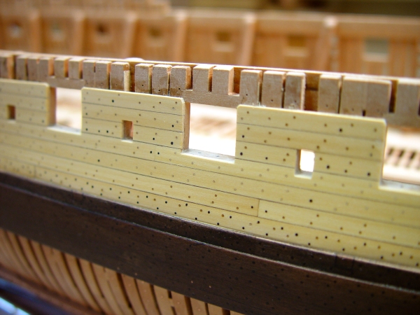
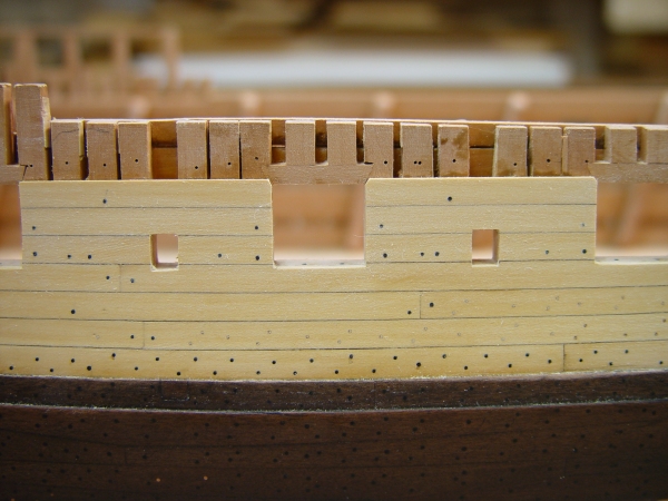
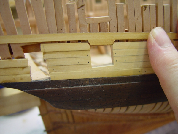
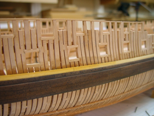
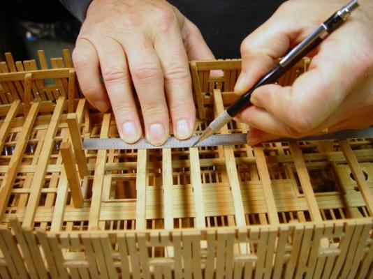
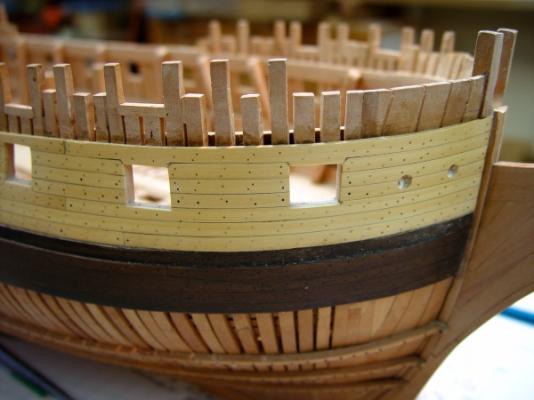
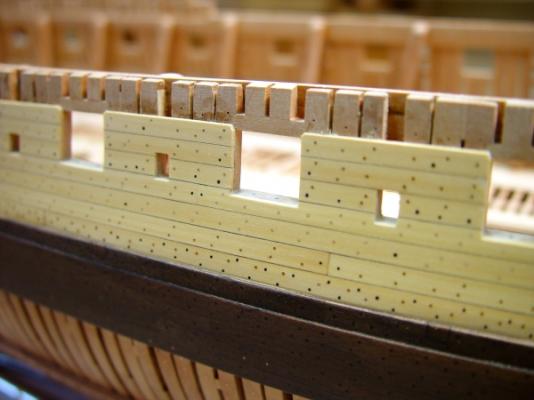
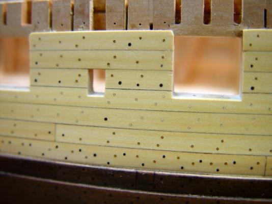
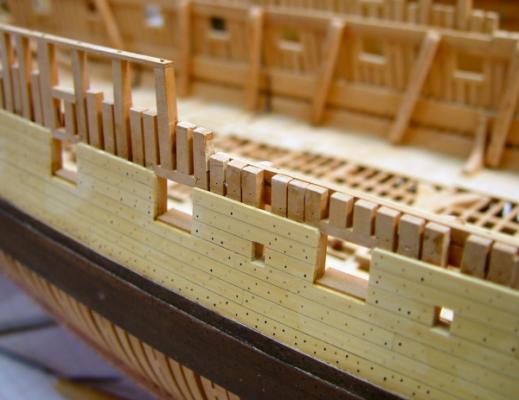
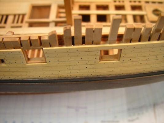
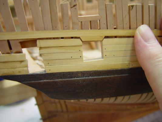
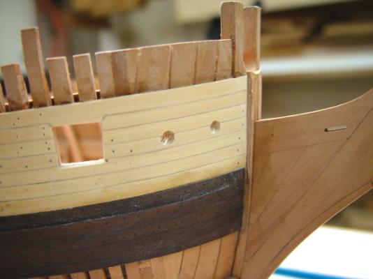
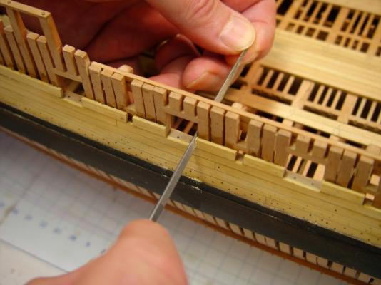
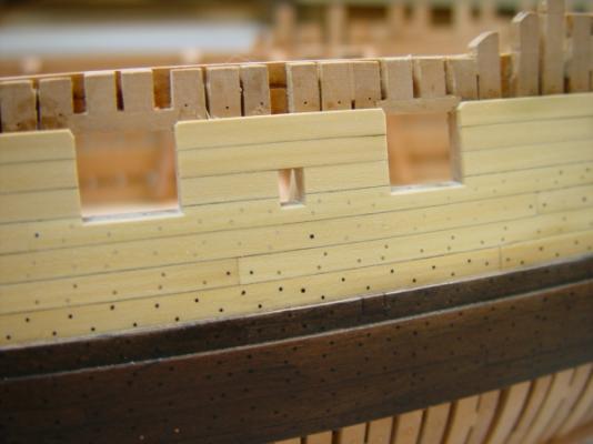
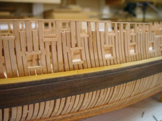
1:60 HMS Naiad 1797 Part 97 – Port Stops Posted 9/10/11 The treenailing and bolting of the seven strakes of planking above the black strake was completed this week. The next three pictures show that stage of completion. The purpose of doing this outside planking was to be able to install the port stops – the window frames, if you will, on the sides and bottom of the port framing. These will be discussed below. In the above picture the hawse holes are only roughed in. They still need to be sized and lined. This picture shows some typical bolting and treenailing. The lowest yellow strake is loaded – with both treenails and bolts for the lodging knees of the upper deck, which still have to be installed on the inside. The next picture is a close up of this area. I mentioned before that the treenails are about 1 ¼ inch. There are also 1 3/8 and 1 ¼ inch bolts. The pin holes above the top strake are left from the temporary ribbands that were removed earlier. They are at the level of the sheer strake and sheer rail. In the next picture the horizontal port stops have been installed. These lay flat on the sill and their outside edges are at the inside face of the planking. Their insides were oversized and get cut off flush with the inside of the frames. The next picture shows the inside being finished off flush after the side stops were installed. I knew when I put the riders in that I was creating a future headache for myself, but they really needed to go in before the upper deck beams and knees, even though it would mean slipping planking behind them. It also presented a problem in facing off the stops. The first step was to pare these back using a chisel and a curve-bladed scorp – not shown. This was followed by filing flush using the bent-handled file, as shown above. This all went surprisingly quickly. We’ll see how the internal plankng goes. The notches in the upper deck clamps are the openings for the lower deck ventilation scuttles. The next picture shows some stops after facing the insides. These stops are 2 inches thick and are placed on the bottom sill and the two sides. They serve to stop the closure of the port lids and probably were fitted with oakum or some kind of gasketing to keep the water out. The ones for the sweep ports are 1 inch thick. The next picture shows the inside after the stops were faced off. The next major task in here, after installing the remaining few standards, will be to install the upper deck beams followed by the waterways and spirketing, which will go right up to the top of the lower sills. With that done the scuppers can be drilled out and lined. The next picture just shows a few of each type of port finished off. The boxwood has been sanded pretty well at this stage – up to 400 grit. No other finish will be applied to this until all the rails and other external fittings are installed – the steps, the scuppers, the fenders, chesstrees, etc. – way down the road. Ed


-
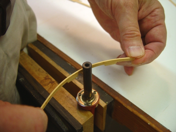
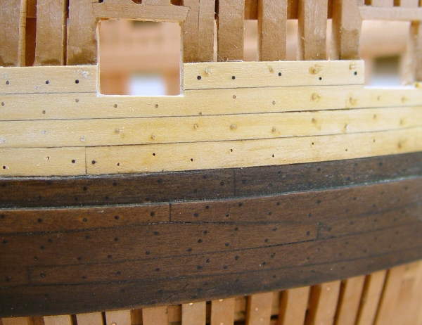
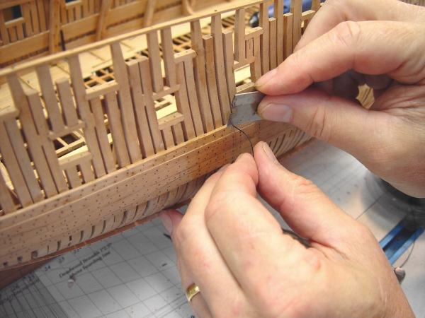
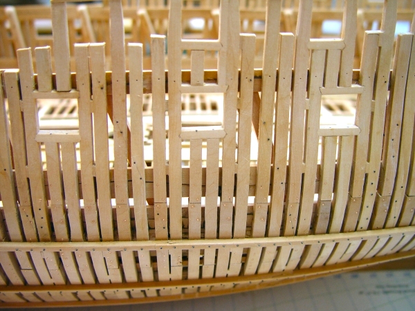
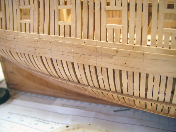
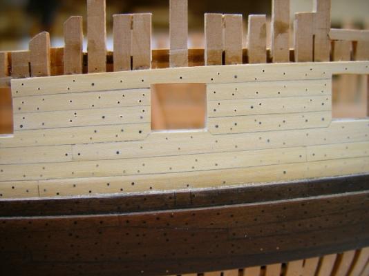
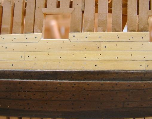
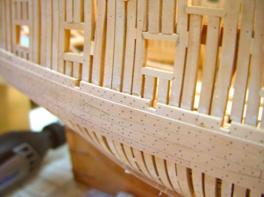
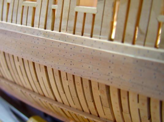
1:60 HMS Naiad 1797 Part 96 – Outside Planking 3 While the remaining planking was getting installed, I started installing bolts. My process here is to install all the bolts first, then go back and do the treenails. In some cases the bolts will be placed so that some treenails are not needed. The picture below shows an area with the bolting installed. All the closeups have lens distortion. Believe me that line of frames at the top is not curved up. In this picture there are a few different bolts. The double row at the bottom of the boxwood planking is for the lodging knees of the upper deck. The two rows of four large bolts each slanting up to the right are for the internal riders. On either side of each gun port there are three bolts, which on the inside will be eyebolts, a large bolt for the breeching, a smaller one on further out on either side for the training tackle and a smaller one above the breeching bolts for trussing the gun up. In addition there is one bolt at the butt of each plank, except for the short planks between the ports. In the next picture the highest strake above the ports is being fit up. The two strakes aft of the quarter gallery door have yet to be installed. After this plank is installed the opening will be filed up to the top sill. In the next picture one of the last bow pieces is being shaped to a curve using the shaft of a small soldering iron to heat the concave side. For this thin boxwood planking this is much faster than steaming, which is the approach I have been using on the thicker structural pieces or where some edge bending is needed. This piece will fit above the bridle port and port number one. The next picture shows it in place. This is the last strake for now. It fits right up under the knighthead and is flush with its forward face. It was nice that this strake just fit. There is still some finishing work to be done to clean up the stem and the ends of some of the planks. The hawse holes were roughed out before these planks were installed, drilled with a smaller drill then filed open parallel to the keel with a slight downward slant.. they are not finished, but I wanted to get a hole through the planking. In the next picture the drilling for the treenails is in progress. More distortion. The pattern here is alternating between two nails and one nail in each frame along the plank with the pattern offset for adjoining strakes. The bolting prevents the pattern from being completely uniform, but I suspect that was pretty much the result on the prototype. The next picture shows the planking for this phase all installed, except for treenailing and some bolting. The next picture is just another view. These last wo pictures are pretty representative of the true colors of the different woods. After finishing the treenails – or maybe sooner – I will be returning to the inside work. Ed


-
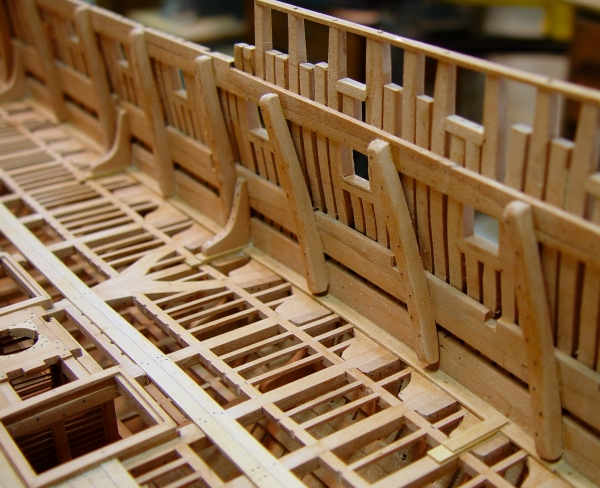
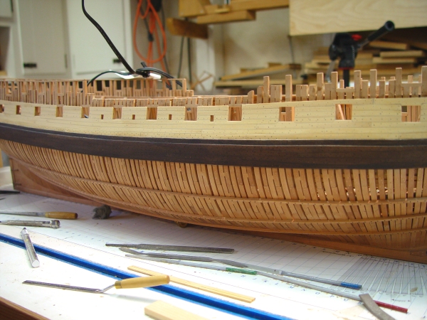
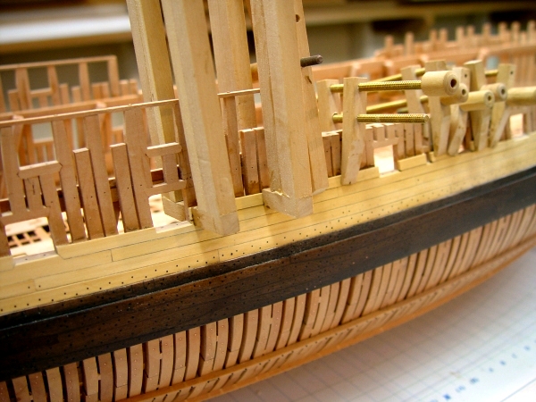
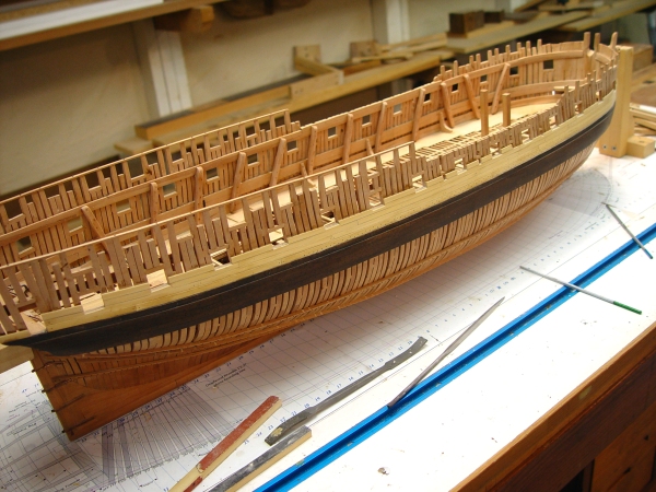
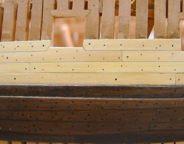
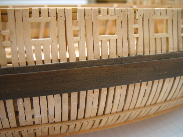
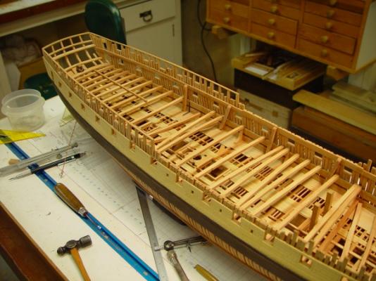
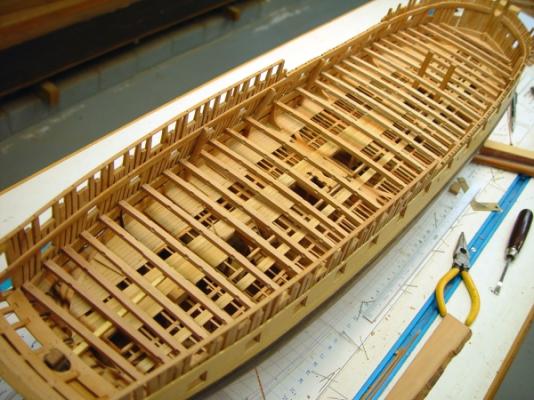
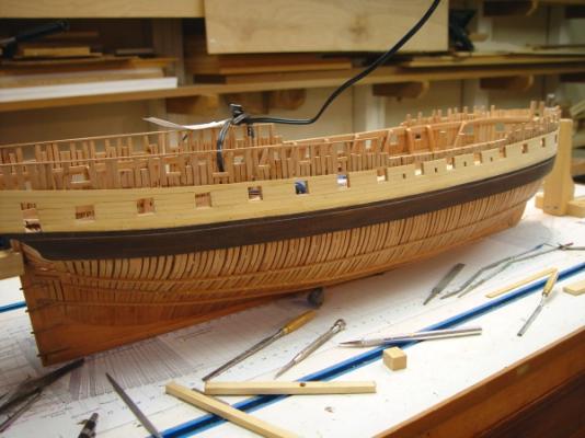
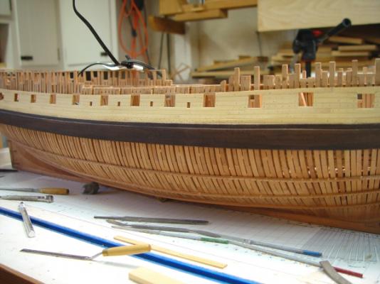
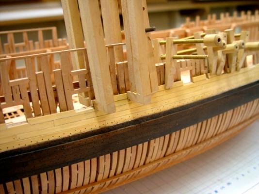
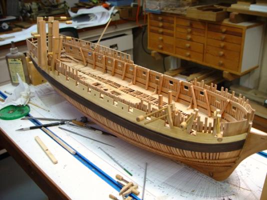
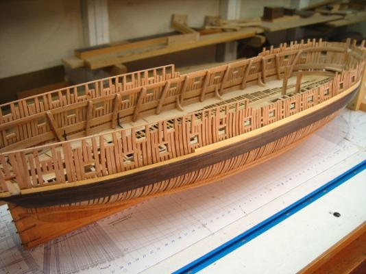
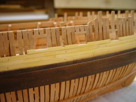
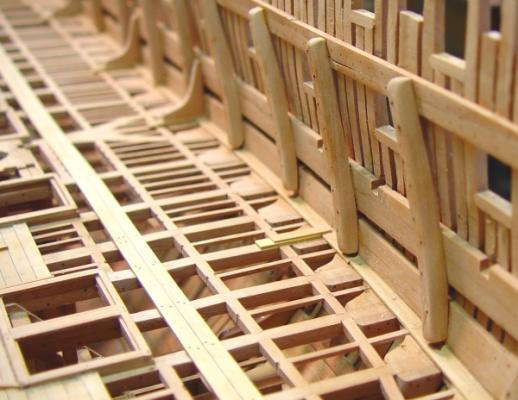
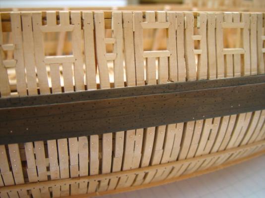
1:60 HMS Naiad 1797 Part 95 – Outside Planking 2 Posted 9/1/11 Planking on the starboard side of the hull continued this week. The first picture shows pieces between the ports clamped during gluing. Planks are 3 ½” thick at this level. The planking in the waist area is now getting close enough to the topside to allow normal screw clamps to be used. The planks are being glued in with darkened glue and before being ripped off a wide strip one side of that strip was given a coat of light brown acrylic paint to help highlight the joints. The next picture shows progress up to a few days ago. In the next picture the excess ends of the planks are being removed with a #0 Barrette file. This does not cut on its edges. The next picture is a close up of the current state. The planks have been leveled off and given a preliminary sanding. Final sanding and polishing will await the treenailing. The black bolts in the strake above the black strake are mostly bolts for the lodging knees of the upper deck, which runs at the same height as this strake in the midship area, dropping down below it as the ends are approached and the curve of the sheer becomes higher than the curve of the upper deck. The two larger bolts in the center of the picture go into and through the internal riders. The lighter fasteners are .019 inch bamboo treenails. The chamfered corners of the top planking pieces in this picture will seat areas of increased width in the next plank up, as was done on some of the planks below the ports. In general, this was done wherever the cut out plank width would have left less than half the original width. The waist rail, a molded decorative rail will eventually be installed along the center of these ports – approximately at the height of the plank just above the sweep port in the picture. The next picture is a close up from above the side at the waist. The last two planks up in this area, not installed yet, will be thicker and joined at their ends with hook scarph joints. They will Take the external planking up to the level of the strings and tops of the frames in the waist area. The last picture shows the whole hull in its present state. Cheers, Ed


-
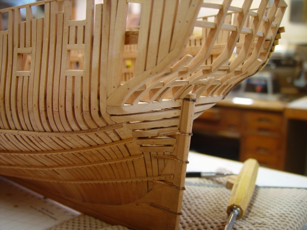
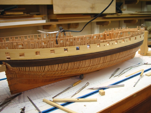
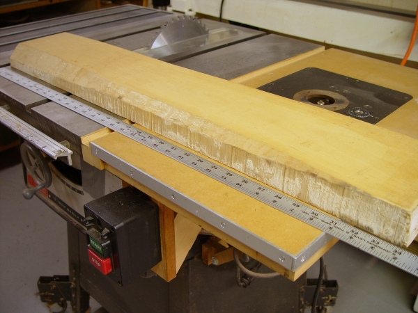
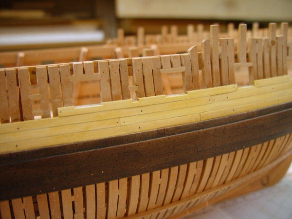
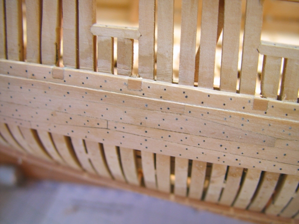
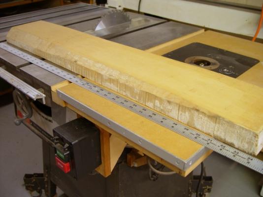
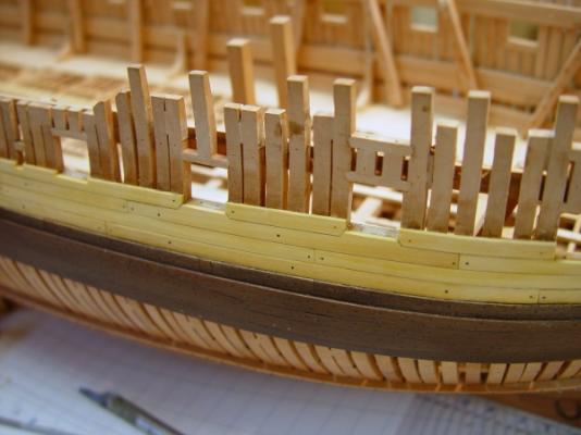
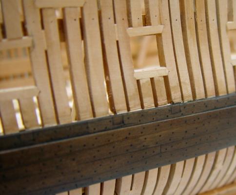
1:60 HMS Naiad 1797 Part 94 – Outside Planking 1 Posted 8/26/11 The first picture shows the model at the stage we left off in Part 93. The wale is finished and I was contemplating starting the exterior planking on this side above the rail. I would like to get the planking finished up to above the ports so the port lid stops can be done before doing the upper deck spirketing. The spriketting goes over the stops. The first step was the most difficult. In the next picture I am about to cut into the last of two beautiful pieces of European Boxwood, buxus sempervirens , that I bought in the 1970’s. Cutting this was painful. These pieces were virtually perfect with no imperfections or discoloration. If anyone knows where I can get more like this one, let me know. I wanted to use this for the yellow of the external planking, but also for other exposed rails, details, etc. I used the first one of these on Victory and for other things, tools, etc. The next picture shows the first strake above the black strake partly installed. The dark yellow is still wet from washing off the glue. This is where I miss using ebony for the wale. The finishing of this strake is almost impossible to do without marring the black finish on the top corner of the black strake. The next picture shows the full hull at this stage. This is one of those rare moments when everything was cleaned up and uncluttered. The picture below shows the planking rising up around the lower deck ports. In this picture the bolting has begun. There are several large, 1 3/8” bolts in slanting rows for the internal riders. There are also smaller, 1” bolts at the end of each plank. The plan is to do the bolts first, then fill in the rest with the treenails. Below is another picture taken at this stage. There is still some leveling of these top strakes to be done. These pictures help me find things that I don’t see as readily with my eyes – like that slightly protruding plank just aft of the right hand port in this picture. This picture also shows the planking cut out at the bottom of one of the sweepports. The next picture shows some more bolting and some of the first treenailing. There are three bolts through the side on each side of each gun port. The pairs closest to the opening are large bolts for the breeching eyebolts and the next two, one through each of the next frames are for the training tackle eyebolts. These will not go all the way through on the model. The treenails in this picture are added to supplement the bolts, so the pattern is a bit random. The last picture shows some treenails installed further forward. These have not been filed down as yet. Holes are drilled for the lowest strake but no nails yet. The treenails .019” about 1 1/8”. All these close up pictures show some distortion that makes their centers bulge a bit. Work has been slow for the past couple weeks, but I’m hoping to up the pace a bit in the next two weeks. Cheers, Ed

-
Thank you all for the comments. Greg, the clamps are just a variation of the simpler two-screw type shown earlier made with Castello and 6-32 threaded rod. I dded reinforcement on the backs of the first, thiiner legs after breaking a couple. On the Euro Boxwood paint, you had me going for a minute. Its not a paint but a species of wood - European Boxwood aka English boxwood - sp. buxus sempervirens - or just plain boxwood, although Castello, a tropical species, has co-opted that name to a large extent. They are not the same. More on that in the next repost, which I will do now, considering your question and the great comments. Ed
-
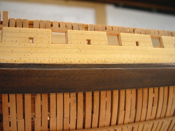
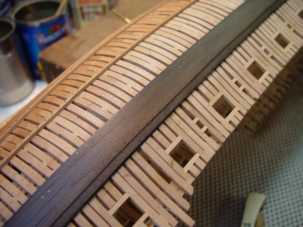
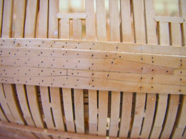
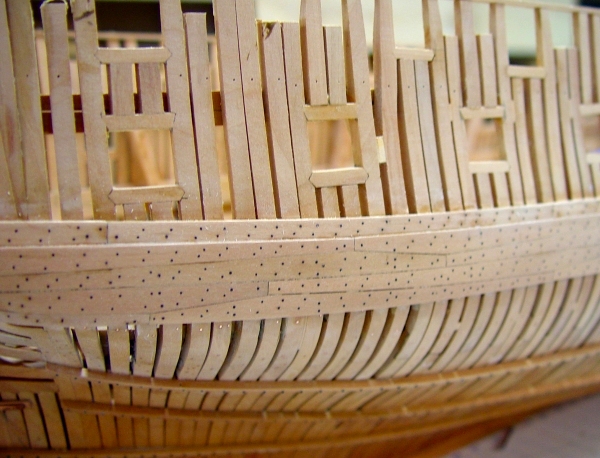
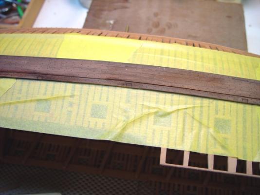
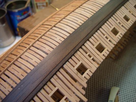
1:60 HMS Naiad 1797 Part 93 – Vent Scuttles –Wale Finish Posted 8/8/11 More has been going on in the last two weeks than was shown in the last part. There are 20 9” X 7” scuttles on the lower deck for ventilation and light, 10 on each side. There is one in each of the officers cabin aft and everybody else gets to share the other eight, four on a side. But before getting to those, in response to questions, I wanted to share one picture showing how the monofilament is cut off flush with the top of the planks. This is done immediately after inserted the filament with CA glue, so the glue can be washed off with acetone before it sets or pentrates too much into the wood. The razor blade tends to get glue on it, so I use two. When one gets gluey I drop it in a jar of acetone and use the clean one. In maybe 5 minutes its time to change. The acetone dissolves the CA almost immediately. So, what about these vent scuttles. The next picture shows three of these cut into the black strake. They slant upward 4 inches or so from inside to out and this puts them roughly on the line of this plank. On the inside as seen in the next picture they are cut into the deck clamps. The trick with these is to get them positioned between timbers, in the correct cabin, while avoiding the riders, the knees the beams, chain plates, etc. This is not easy and I spent some time placing them between the different views on the drawings before settling on their locations. For the sake of neatness they are all cut so their tops are flush with the top of the black strake outside and the clamp inside. This leaves the inclines within a few inches of what Steel says they should be. The next picture shows the doors installed. These will eventually get horseshoe hinges but for now they are just glued in with very dark glue. On the other side where there is no planking they will show the cuts trough the frames in more detail. Since some of these cut a few inches into the frame I suspect that reinforcing fillers were put between the frames at these points, much in the way it was done near the chain plates, or gun breechings and in some other areas. In the next picture the wale is in the process of final sanding and polishing before getting blackened. The scuttle doors are barely visible here. After this picture was taken I did accentuate their borders with a chisel point. So, on to the finishing of the wale. A lot of thought and also a lot of input from people on the forum went into this. I believe I did mention the final decision on the process, but briefly it uses a dilute black stain made with Speedball acrylic black ink in water. The wale was sanded with grits to 320, then buffed with Scotchbite pads. It was wetted a few times between final sandings to pre-raise the grain, which was then sanded off. After the first stain coat the surface was checked for light spots and there were some where the CA penetrated around a few of the bolts. This was re-sanded. The next picture shows the wale drying after about the third or fourth coat of ink stain. Before each coat the surface was dampened, either from the previous coat of ink or with a damp rag to keep from blotching. There were eight to ten coats all together until it got to a shade I wanted where the plank joints and bolting could still be seen. The ink was very dilute so I would approach the final shade slowly. The next picture shows the final shade. The picture was taken after one coat of Watco oil was applied. This was done after the ink was completely dry. It was preceded by buffing with Scotchbrite. A total of less than five drops of oil were used, on a Q-Tip and the surface was then buffed dry with a cloth. This buffing was repeated about 20 minutes later when some of the oil came out of the pores – which it likes to do. The next picture is a close up of the wale. And the last picture is another view. I’d say these three last pictures give a pretty accurate rendition of the finish. More oil will be applied. This is for protection. In the above picture the fasteners, the planking seams, the scuttles and some of the wood grain are showing. The area above the black strake will be planked in Euro Boxwood so I was not too particular about keeping that framing pristine. There are file marks and ink. Wdith this done, the outside planking and parallel work on the inside can proceed. The area below the wale can also be given its final wax finish. Ed


-
1:60 HMS Naiad 1797 Part 92 –Top Riders/Main Wale Posted 8/7/11 After the last report the rest of the top riders were made and installed. The first picture shows one of these being fitted on the starboard side. The next task was to install the bolts for these. There are eight in each. In the next picture a monofilament bolt is being slipped in with CA glue. It will then be cut off flush like the one below it. The following picture shows the rider bolts installed on the outside where there will be no planking. The riders usually hit three or four frames with two bolts in each. To keep the bolts in neat rows inside and out the holes are drilled and the filament inserted from each side. I just haven’t found a reliable way to drill al the way through and get a neat result. To the right of the picture is a vertical row of bolts for one of the lower deck standards. Below is a picture of the rider bolting finished on the inside. This wood work still needs final sanding and some polishing up. The strips on the deck are to anchor the cabin partitions. The next picture shows the beginning of bolting through the wale. The angled lines are for either riders or for dagger knees. I believe all those in the picture are for riders. The vertical lines of bolts are for the hanging knees or standards. On the wale black monofilament is being used for both the bolts and the treenails. In the case of the nails this is to make them show up after the wale is blackened. The treenails are smaller. The strategy for this was to install all the bolts first, then fill in nails where a bolt is not already in place, two per frame. These include bolts for the riders, lower deck knees and one at eac butt on each wale plank. In the above picture bolts for the knee are being installed one at a time from the top down. And only some of the rider bolts are in. The horizontal row of copper bolts below the wale are holding the lower deck lodging knees and some of the bolts for the hanging knees are also visible. Except for a few copper bolts for the lower deck spirketing, all the wale bolts are black iron. The next picture shows the difference in size between the bolt and the treenails. It also shows the nailing pattern where the nails fill in around the bolts. The last picture shows a section of the wale with all the bolts and nails installed. There are about a thousand fasteners in the wale, a time consuming task. In the next part we’ll finish up the wale with the cutting through of the lower deck ventilation scuttles. Ed