EdT
-
Posts
2,214 -
Joined
-
Last visited
Content Type
Profiles
Forums
Gallery
Events
Everything posted by EdT
-
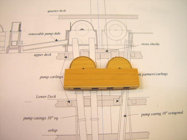
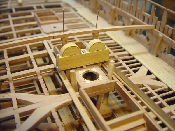
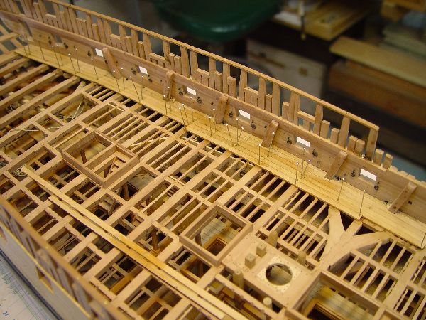
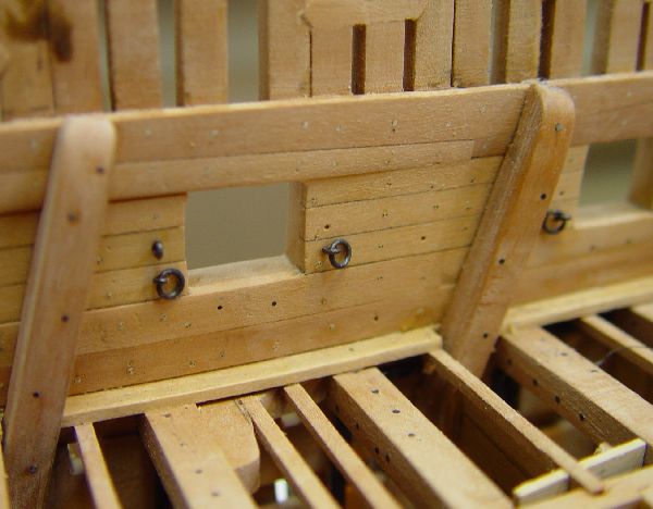
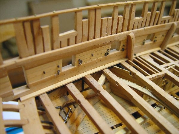
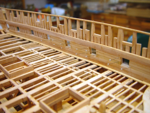
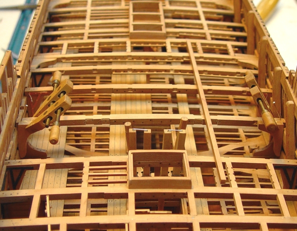
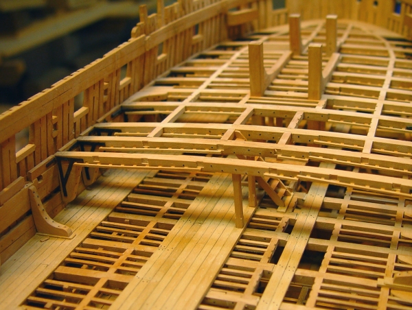
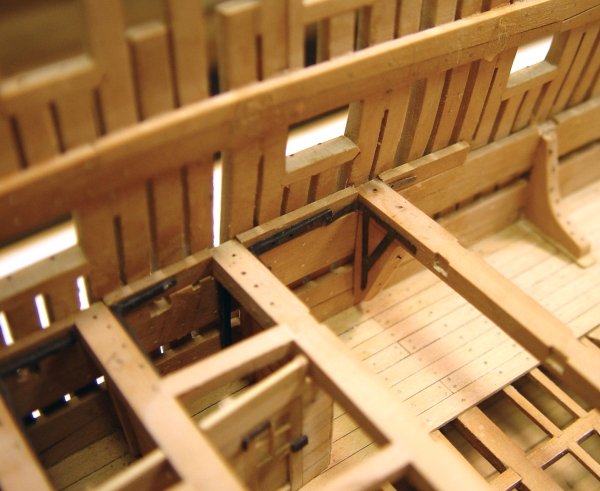
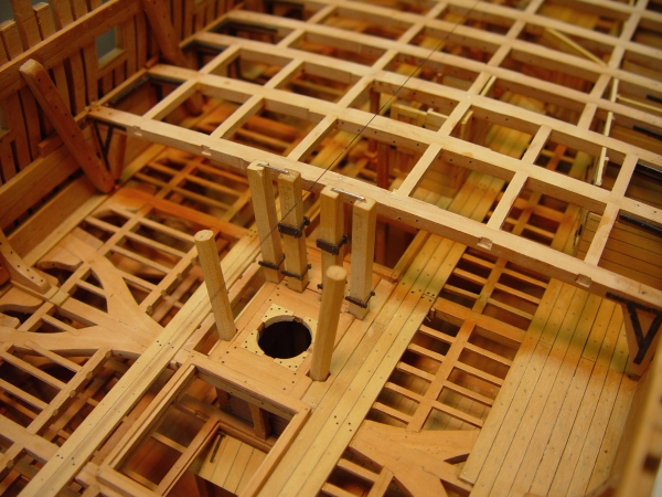
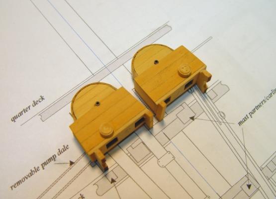
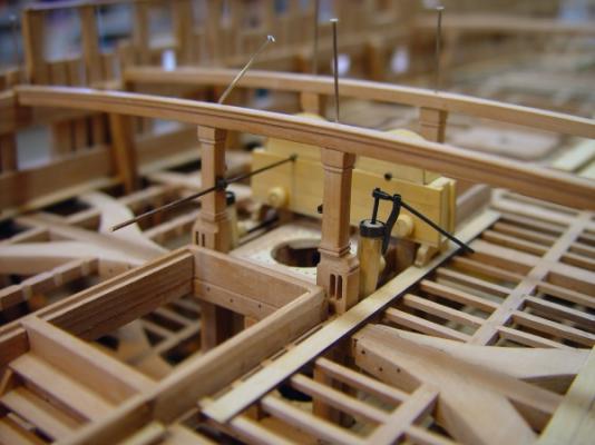
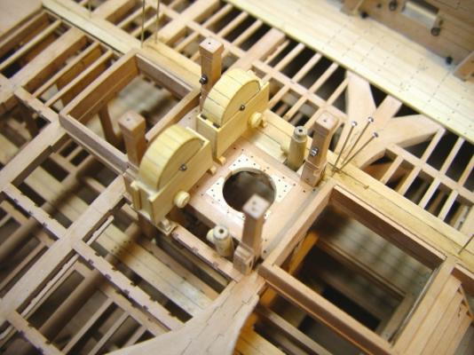
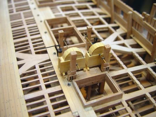
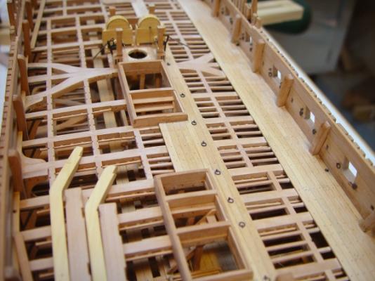
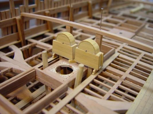
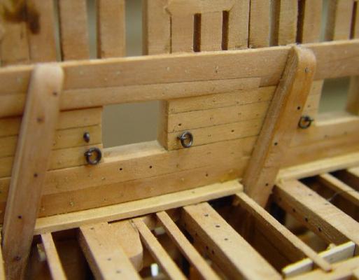
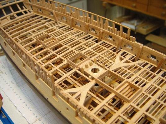
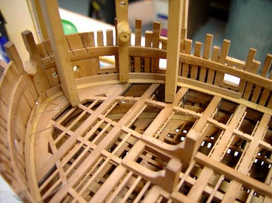
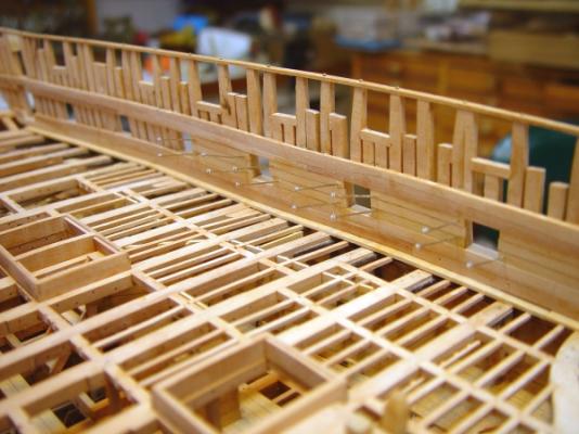
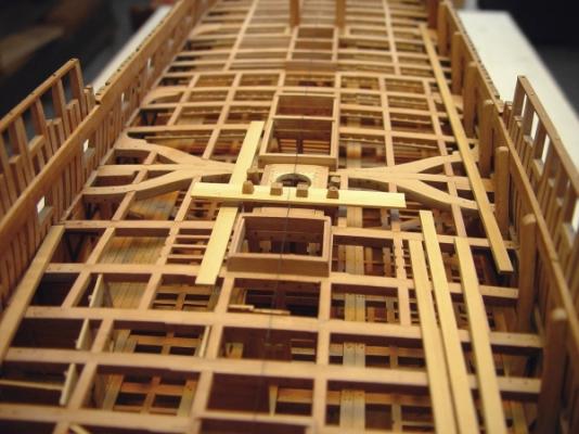
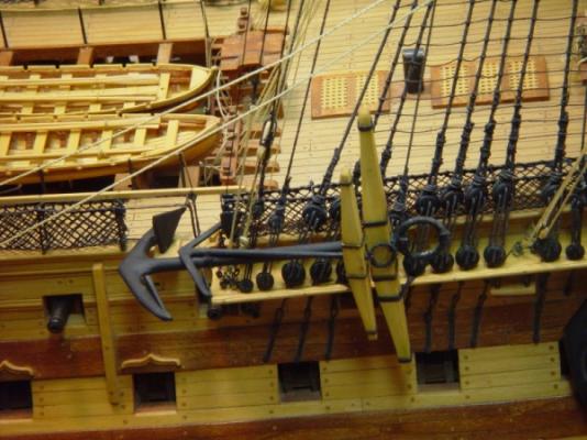
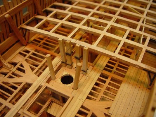
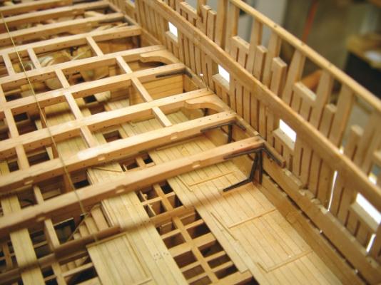
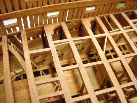
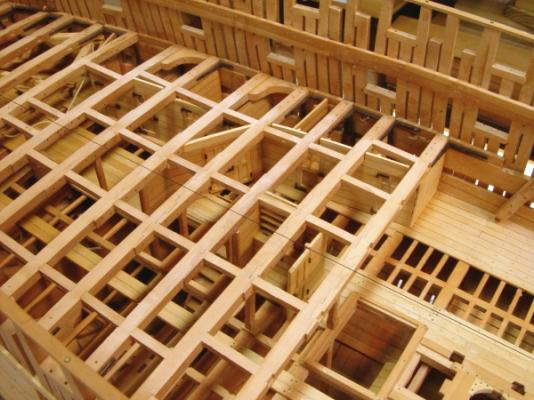
1:60 HMS Naiad 1797 Part 124 – Upper Deck Detailing (3) Posted 3/1/12 The steering wheel has had me pre-occupied for awhile, but other work on the upper deck has been moving ahead, mostly in the area around the main mast. The first picture shows the two cisterns /top-works housing for the Cole pumps getting some detail – feet, shaft bearings and plugs for the drain holes. The next picture shows the two elm tree pumps with their top works. These parts were made from brass, silver soldered and blackened. They are slipped over the tops of the octagonal casings only temporarily. The next picture shows the pump components temporarily positioned on the deck. The jeer and topsail sheet bitts are not attached yet. They still need sheaves. The “rhodings” for the crankshafts have been installed on the bitts in this picture. These were fabricated from small bore brass tubing silver soldered to a length of brass strip then sliced off on the saw to make the small bearing. The alignment of the pumps and the posts are obviously important here. The next picture shows a somewhat later view of this. In this picture the deck planking is proceeding. The cut out plank around the pump casings has been installed. The discharge nozzles have also been installed on the elm tree pumps. One on each just above the upper deck and one on each – not visible - to service the lower deck. These shafts have been permanently fixed at this stage. In the next picture sheaves in the bitts have been installed and also handles on the pump drain plugs. All four pumps and the bitts are permanently installed at this point. The cross pieces to the bits have not been installed. The pump shafts are just temporary – to maintain alignment while gluing the pumps in place. The sheaves in the bitts are just visible in this picture. At this stage the decking is complete, treenailed and polished up except for some at the aft end. One of the gun ringbolts can be seen in the above picture. The next picture, looking forward, shows some more ringbolts. Those forward of the main hatch are large sized stopper bolts. These doubled as gun bolts. Aft of the main hatch a smaller ringbolt is positioned to serve each gun. These are smaller diameter. The next picture shows more of the stopper bolts going forward. There was one of these stopper ringbolts in each beam. The eyebolts are semi-sunk into the deck. I made a small tool out of a 2d nail to make the indentations for this. I did not use any glue on these. They are made from copper wire and were blackened before installing. The outer decking in this picture is finished and all this decking and the upper deck framing could be given a wax finish at this stage since there is nothing else to be glued to it. There are still some training eyebolts to be installed between the ports. Ed


-
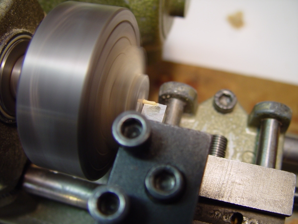
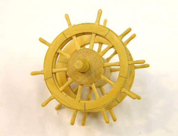
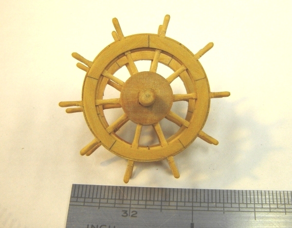
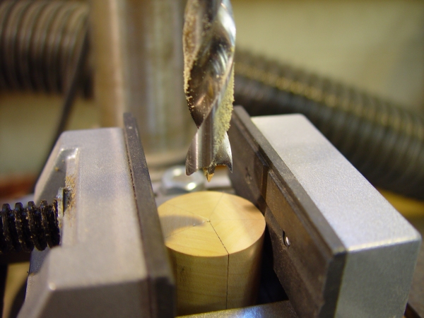
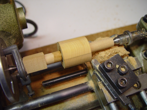
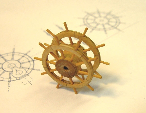
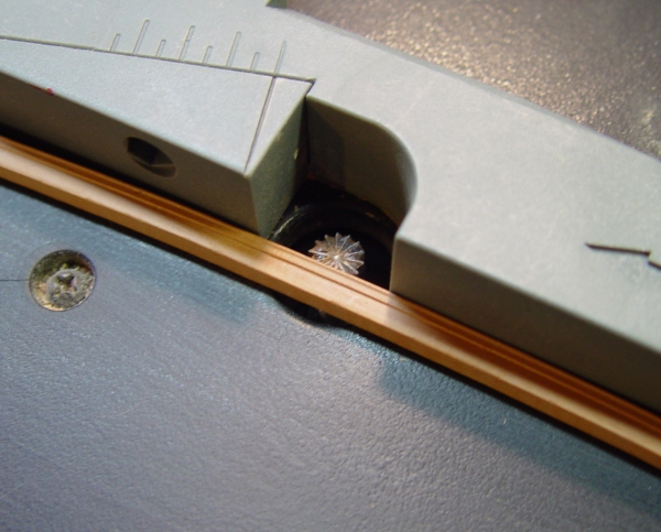
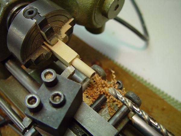
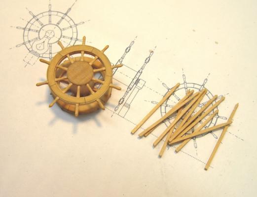
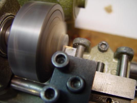
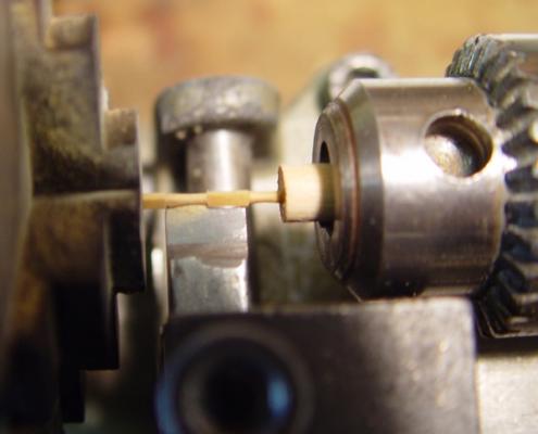
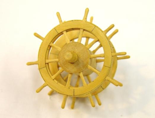
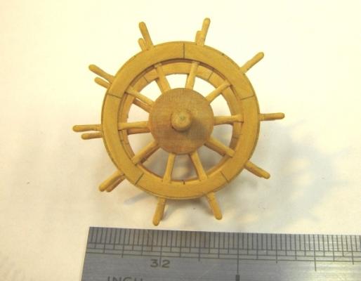
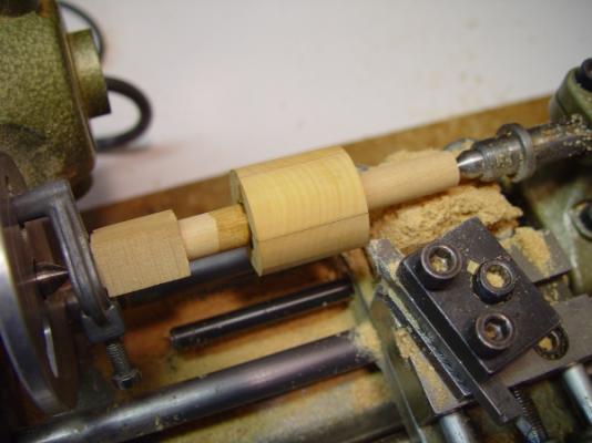
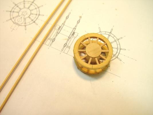
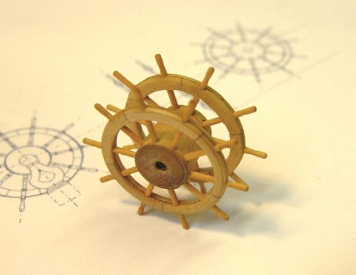
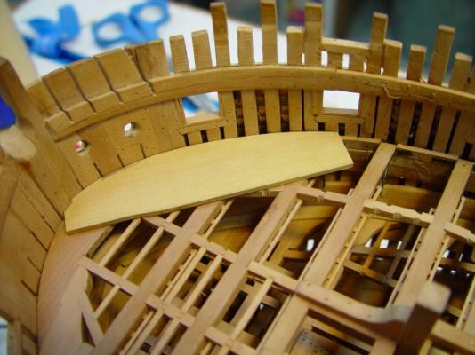
1:60 HMS Naiad 1797 Part 123 – Steering Wheel 2 Posted 2/25/12 In the last part I generally described the process used for making the wheel rims and the hub assembly. The goal was to make each rim as an assembly of segmented pieces with their joints offset and to have a precisely spaced, regular pattern of the ten spokes set between those joints. Most of the responses to the post focused on making the spokes, and the difficulties of turning these small pieces. Although I was concerned about turning the small spokes, I was surprised to find it took only two days to get a reasonable set of spokes made and installed – as opposed to over two weeks to on the rims/hub assembly. Turning these small squares is a lot harder than turning full size table legs. It took some experimentation to get a workable turning process, so I will discuss the final method in some detail for those who want to try this. The first picture shows the first set of spokes inserted in one rim and the second set waiting to have their center portions turned. The spokes are 2 ¾” (.044”) square and were turned from square strips of European boxwood. The turnings came out reasonably uniform in shape – acceptable (by my standards, at least) for this scale. The next two pictures show the pieces being turned in my ancient Unimat SL. Two profile cutters were used, one for the handles and one for the turning between the rim and the hub. Their shape was adjusted by trial and error until a reasonable turning could be made without instant breakage of the part. The cutters were ground and filed to shape from ¼” square mild steel bar stock. The top edges were set precisely to the centerline and honed smooth with a stone. The relief angle under the cutting edge was small – about 10-15 degrees. These are really scrapers. The handles were turned first. They were set up in an independent four-jaw chuck. Getting the square strips centered was non-trivial and very important to get a successful shape. The depth of cut is less than .01”. A number of other factors were important in reducing breakage. First, the pieces were turned at very highspindle speed – 12,000 rpm – flat out on the SL. The tool feed was done very, very sensitively – in steps of much less than one graduation on the wheel – with periods in between to allow the part to re-center. The tool was kept as close to the chuck as possible as shown in the picture. Everything was set up to be as rigid as possible on this machine. There is flex in the Unimat bed, so the feed wheel had to be handled very lightly. With all these precautions the yield on handle turnings was about 50-60%. The next picture shows the setup for turning the center sections. All the procedures described above were followed in this step. In addition, a wood centering bearing was drilled to support the handle end while turning the center section. This is shown above. The yield on this step was better – about 80%. Although I am using European boxwood for the wheel, I also tried doing some turnings using Swiss Pear and Castello. Both these species could be turned in the same way. The next pictures are of the (almost) finished wheel. The wheel assembly was held together by temporary spokes when it was finished off in the lathe as described in the previous part. These were removed one at a time when the permanent spokes were installed – to preserve the alignment and concentricity. These are not glued – at least not yet. They are fairly tight in the holes. The wheel will be exposed for some time on the open deck. If any spokes get broken, they can be pulled out and replaced – or if I decide I don’t like the looks of one or more. . . The last picture shows the wheel next to a ruler to help visualize the 1:60 size. The rims are slightly less the 1” diameter. I am still thinking about fasteners (bolts) for the rim segments. I will probably use the version-one wheel to test some out. I hope this detailed discussion is helpful for those who want to turn some square spokes. Ed
-
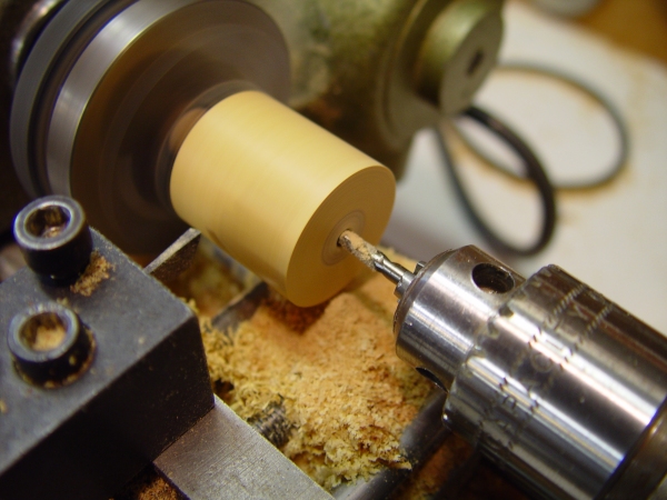
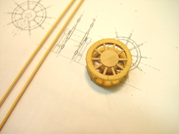
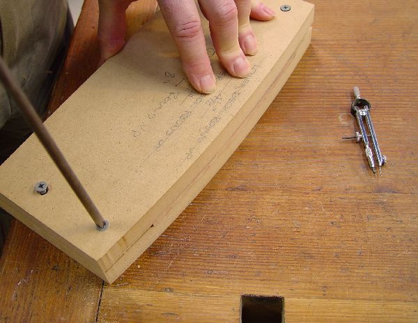
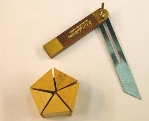
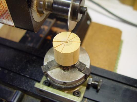
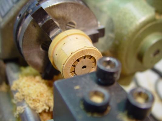
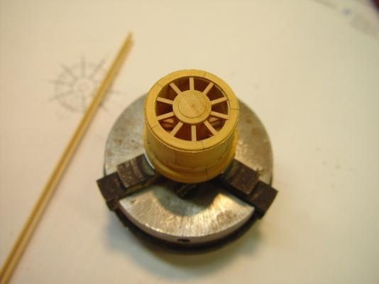
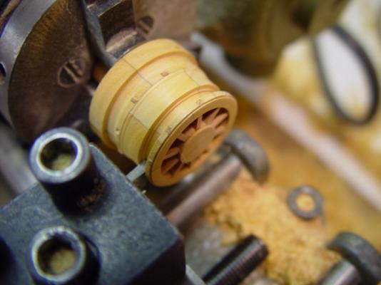
1:60 HMS Naiad 1797 Part 122 – Steering Wheel 1 Posted 2/23/12 In the last part I mentioned work on the ship’s wheel. I wanted the wheel to be built up as a five piece segmented assembly with the joints offset. Also, I wanted the 10 spokes on each wheel wheel to be evenly spaced and to be of square section where they pass through the rim. The process for making this is quite complicated and prone to error. I used up a lot of precious Euro boxwood in working through it. In this part I will outline very generally the steps to make the two-rim/hub assembly. The first step was to form a block consisting of five triangular pieces large enough for that steps that follow. These were cut on a 10” table saw then refined to the precise angle required using a disk sander. The top and bottom were scribed with an oversize circle and the block was sanded to a roughly circuklar shape. In the above picture the cylinder is about to be drilled through for the hub, which will also serve as a mandrel to turn the piece in the lathe. The (oversized) hub was turned between centers to just fit the hole. The parts were then glued together and the assembly set up between centers to accurately turn the outside and square up both flat faces. This would allow the piece to be held accurately by one end for succeeding steps. Maintaing an accurate centering through all the steps was critical. I learned this the hard way. The piece was then able to be held centered in the three-jaw lathe chuck. In this picture a hole for an axle is being drilled. The next picture shows the machining of the square spoke holes for one wheel. Before this step, a disk was parted off the cylinder while still on the lathe. This would be reattached later. In the step shown above square slots are being cut in one face of the cylinder for the spokes using slotting saw blades. The same three-jaw chuck was used mounted in an indexing head with setting divisible by 10. After cutting these slots the disk removed earlier was re-attached to the removed disk piece with the segment joints offset. The next picture shows later work after a series of pieces were parted off, after the slots for the second wheel were cut, and after the pieces were all assembled. In this picture the final assembly is set up for final machining. This will be done in one piece to preserve the alignment of the slots. The inside diameter of the wheels are just beginning to be cut in the above picture. The next picture shows the final assembly after this step and before parting off the wheel rims. Temporary square spokes have been inserted through the rims into the hub. This will maintain the alignment when the rims are parted off. The next picture shows the beginning of the parting off process. The outer rim is being done first. The picture below shows the finished wheel assembly after parting off. The temporary spokes will remain in place until they are replaced with the final detailed versions – one at a time. I will cover the spokes later. They will be .045² square and I am not sure yet by what means they will be shaped. I have skimmed over the steps involved in making this – too many to be described in detail here. Perhaps in the future book I will be able to describe these fully enough for some brave soul to follow them. Ed


-
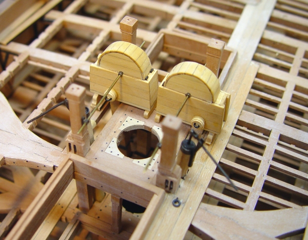
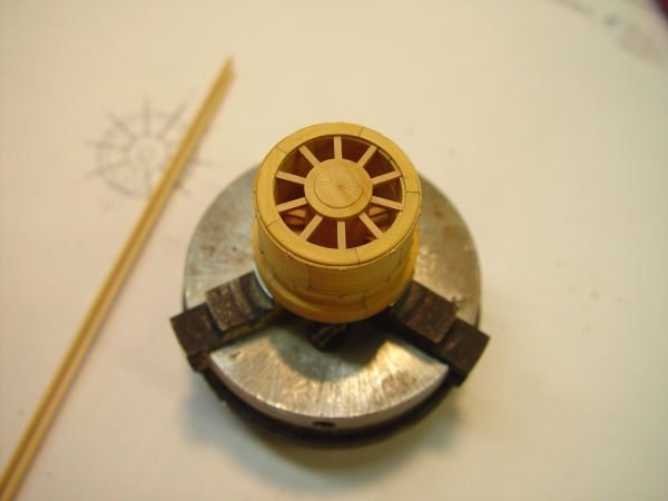
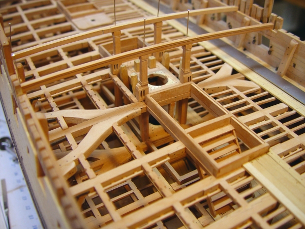
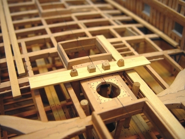
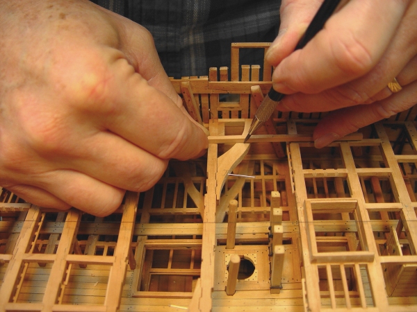
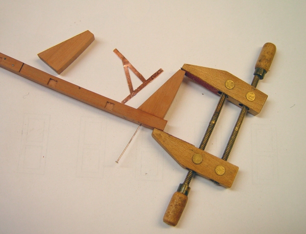
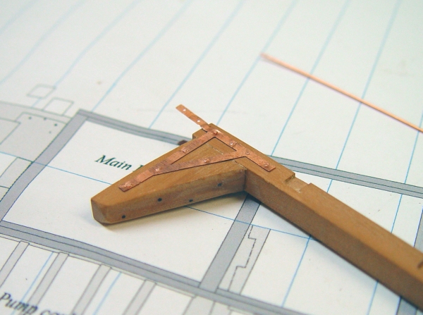
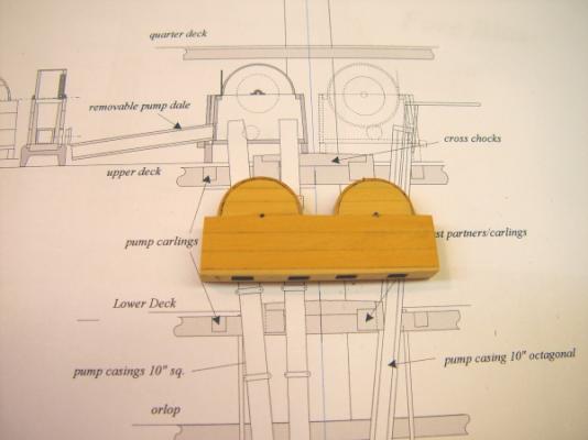
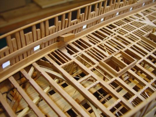
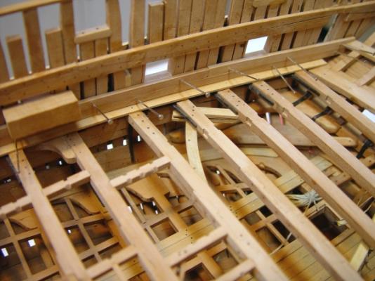
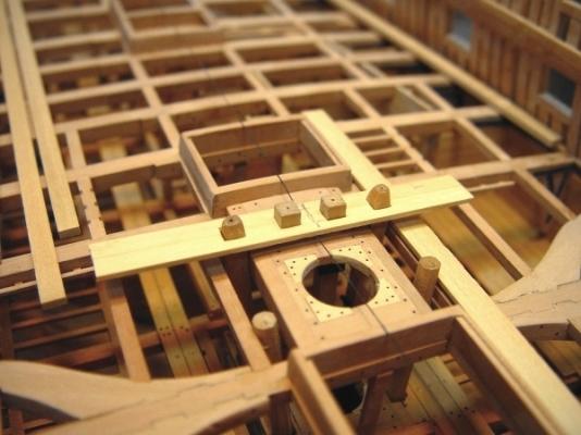
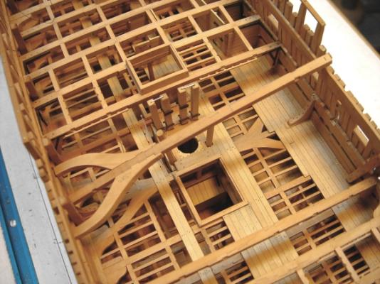
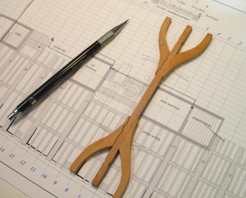
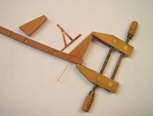
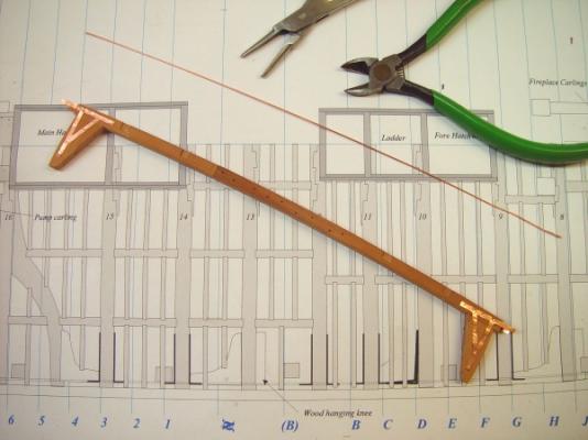
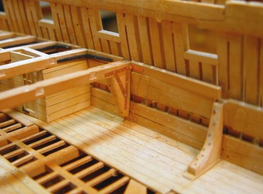
1:60 HMS Naiad 1797 Part 121 – Upper Deck Detailing Continued 2 Posted 2/20/12 It has been a couple of weeks since the last post. I have been working on a number of different areas of the upper deck and it has taken time for some of this work to come together. In particular, I have spent a lot of time working on a process to make the split rim segmented wheel assembly. I will report on that later when I have finalized the method and produced the final wheel. Here is a picture of the first attempt. This was made using Castello. I am not entirely happy with it and expect to make a replacement. The final version will be boxwood. The purpose of this picture is to show the segmented split rim with offset joints and the symmetrical spokes. That part I’ve got down. I would like to have square spokes but that may not work out. I’ll describe the process later. The next picture shows some progress toward the bow. The first beam has been installed with wood lodging knees and iron hangers. The as yet unblackened copper hanging knees are curved to avoid the ports. Planking in this area is in progress. The next series of pictures covers the work around the mainmast. This involved a lot of interdependent components – the beams, the topsail and jeer bitts and the pump cisterns. The first picture shows work on the breast beam, This beam and the one at the forecastle are deeper than the rest because they incorporate a rabbet on the top to bed the ends of the quarterdeck (or forecastle) planks. This picture shows how these rabbets were cut using a Dremel router table. This tool is not as precise as the milling machine but for routing, the high speen of the Dremel tool gives a much smoother cut. The forward face of the beam has a molding decoration. This was made using a small scraper. The next picture shows this beam pinned in place with the roughed out jeer bit pins being fitted. These pins support the beam and are scored on the upper and lower deck beams. In this picture they are pinned in place after having their length adjusrted. Some small adjustment in the location of the breast beam was needed to bring it directly over the pins. The pins also need to be spaced correctly athwartship relative to the pump sprocket spacing. More on this below. In the next picture all four pins have been detailed and are pinned in place. Sheaves will be added later, before permanent installation. The next step was to make and place the pump cisterns. The base for these was made previously in one piece to fit neatly over the pump casings. The two cisterns were built on this base in one piece to assure alignment and spacing. In the next picture this assembly is shown temporarily in place. This approach also allowed the spacing between the horizontal crankshafts to be located precisely in relation to the pins, which hold the crankshaft bearings – called “rhodings.” In this step the cisterns are leveled, with stock for the feet sized to fit between the deck and the base of the cisterns. Doing this in one piece helps keep everything lined up and level. In the next picture the assemblies have been separated and the outer feet have been glued on. The inside feet will be added next and then the rest of the detail added to the cisterns. The new, correct length elm tree pump shafts have also been made and await detailing. I still have not settled on the way to support the decking between the mast partners and the pump carlings (the opening for the pump casings). There must have been some small ledges installed here. Anyone with a suggestion? Ed


-
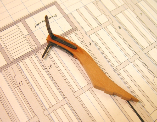
Thank you all for these comments. This work was all done over a year ago, but it seems like yesterday. Perhaps going through it all again in writing Volume II has kept it fresh. Greg, the chock can be daunting, but I believe it can be done quite easily and risk-free. I spent some time thinking about how to describe what I did on this for V2 and included a full description of the process plus a diagram. There are some simple ways to avoid destroying the bollards and ending up with a good fit. Guy, the camera was just a small Sony Cybershot - nothing special. I was suprised at the time at the quality of these and wished I had taken more like this earlier on the decks below while there was still room for the camera. Martin, I use only bolts of copper wire to hold the knees. They are really like small nails. The final installation can then be blackened in place with liver of sulfur solution without having to remove excess glue. That would be a major problem. Just to add a bit of a progress report on the model. I don't want to publish new work until the reposts are finished. The model is almost complete. Most of what remains is exterior iron work - chains, eyebolts, etc. I have reworked some earlier work due to some new information or some disatisfaction on my part. Not much, but a few things, I look forward to posting this soon. Thanks, again, Ed
-
HMS Victory by EdT - FINISHED - 1:96 - POB
EdT replied to EdT's topic in - Build logs for subjects built 1751 - 1800
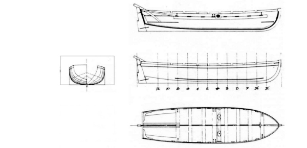
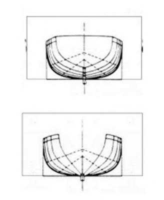
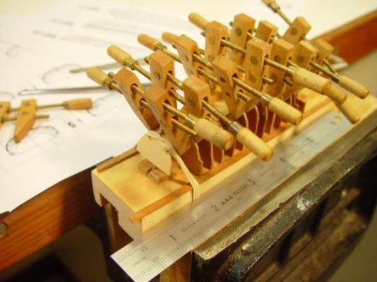
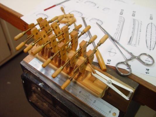
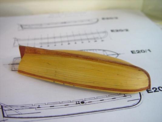
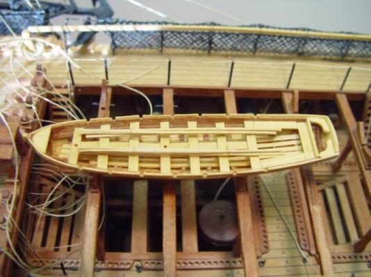
HMS Victory 1:96 Scratchbuild Project Part 10 – Deck Details 3 Ships Boats The ships boats are prominently displayed on supports on the skid beams in the waist, and for whatever reason, the eye seems to be drawn directly to them when looking at the finished model. For years I was aware that they had to be modeled very well, but was stumped for a good process. I spent a lot of time over the years thinking about the inevitable task of building these. Finally a couple years ago, it could be put off no longer. I had a process in mind and in the end I was quite satisfied with the results. Before wading through the details I will show a picture of the finished product. These are only two of the traditionally modeled five. I actually made three, the thirty-four foot launch, the thirty-two foot barge, and the twenty-eight foot pinnace. Only the latter two were installed, mainly because I did not want to completely obscure the view into the waist. The boats are made with scale thickness boxwood planking, cherry frames, stem and keel, and boxwood internals (seats, flooring, oars, etc.). The boats are carvel built, meaning the planks are butted together, not overlapped. The following image is of the 34 foot launch from John McKay’s Anatomy of the Ship Series on the Victory. Many sources of drawings for these boats are available in various books. This one shows the hull profile with frame lines, a body plan and other necessary details. I scanned the image, resized it to my scale and made some modifications which are shown in the next diagram. In the diagram below the image has been split, flipped and re assembled so that all the aft and forward frames are on their own single view. Below the aft frames are on top. In addition, a rectangular box was put around each of these plans. The height of these boxes is the same distance above the top of keel in both images. These boxes define the size of the rectangle of wood from which each frame will be cut. First, multiple copies of these were made, enough so that a frame could be cut from each. They were then pasted on to cherry squares the thickness of the boats frames, about 3” (1/32”). The external shape only of each frame was cut out, leaving the top and sides of the rectangle intact above the gunwale on each. The top of the wood was held precisely to the top line. This would become a datum line on which the framing would be setup for assembly and planking. The next two pictures, taken during the planking process for this boat, show how these frames were setup, upside down, on a block of wood for assembly and planking. First the frame bulkheads are glued upside down onto a block of wood. They are kept aligned with two strips along the sides. Their spacing was matched to the profile drawing. The boxwood transom was then cutout (from the last aft pattern) and glued in place, along with the keel and stem assembly. Boxwood planks, 1/64 ‘ thick and 1/32” wide were then cut and fit into place. A lot of clamping was needed to hold these tight against their neighbors so no gaps would appear. The gunwales were put on early in this process so the planks would end up parallel to it at the top. Stealers were used to bring these planks up fair. This process was described earlier in the section on the planking of the main hull. Unfortunately I have no pictures of the final steps, but once all the planking is done up to the gunwale, the boat is sawed off the frame bulkheads just above (ie below) the gunwale and detached from the wood block. The bulkheads were trimmed down the correct height at the gunwale and were then hollowed out to their final moulded breadth inside the hull. This was done with small chisels. A rotary tool could be used if handled very carefully. It is very easy to split the fragile frames, or worse, gouge through the hull. If done carefully with a very sharp tool, the frames can be reduced to a scale moulded breadth. The above picture shows the finished hull planking on the launch and the last picture is a closeup of the interior of the 28 foot pinnace taken during the rigging of the ship. The oars were made from boxwood drawn down to about .020” in the treenail drawplate. They were then steamed until soft. The blades were then formed by rolling the ends flat and wider, being careful not to oversquash them. When dry the flat ends were impregnated with CA. In the next part, before going on to the masting and rigging, I will cover the very last task done before completion of the model, which was the making of the gunport doors, their hinges and their rigging. These were left until after the rigging was complete so they would not be ripped off by the tangles of rope during during that process. I will then plunge into the rigging. Cheers, Ed Tosti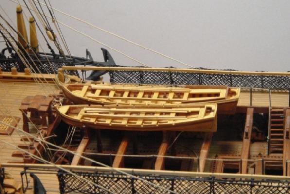
-
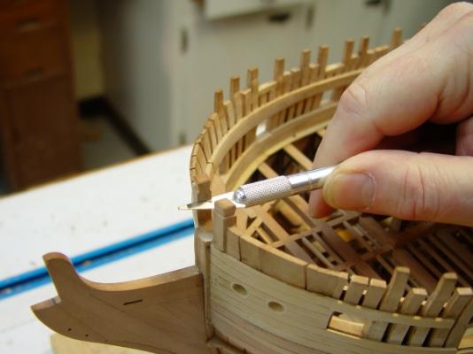
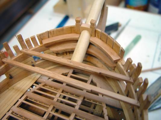
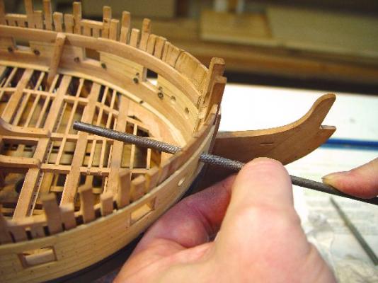
1:60 HMS Naiad 1797 Part 120 – Upper Deck Detailing Continued Posted 1/31/12 After making the beams for the quarterdeck and forecastle, they were sized, fit temporarily in place and pinned to their clamps. As mentioned earlier, some of these beams are needed to complete the detailing of the upper deck. The first picture shows all these beams in place, except for those over the waist. The next picture shows a closer view of the quarterdeck beams. At this stage the beams are set on top of the clamps. No attempt has been made at this stage to score the clamps or set the beams to their final level. The next picture shows the bow area on the upper deck. The linings of both hawse holes have now been completed and the breast hooks above and below them have been installed and bolted. The cants on either side of the hawse holes and the mortises in the bolster below the holes have been added. The opposite unplanked side will remain as is. It was finally time to detail the knightheads. This needs to be done to accurately construct the bowsprit step, which fits between the two decks. First the heads were trimmed to the correct height and their tops shaped. The next picture shows the first step in fitting the tricky bowsprit chock. The top of the chock will be level with the top of the side. The upper horizontal cut for the chock joint is being done using a small razor saw. A triangular space was then cut out below this saw line from the point where the center line of the bowsprit fits against the knighthead, fore and aft. This point is lower on the aft side. The chock was then shaped by trial and error to fit into this joint, mostly using a disk sander. The hole to fit the bowsprit was then opened up at the correct angle using a round file followed by sandpaper on a dowel until the bowsprit gauge shown below just fit inside. The next pictures show the completed work with the surrogate bowsprit gauge of the correct diameter in the hole. The next picture shows this gauge still in place after the forecastle deck hooks on either side were installed.. The opening in the frames for the cathead on the starboard side has been cut out in this picture. The first two beams have been set up to help in fitting the catheads. A fair amount of drafting was required to correctly loft the two catheads. The first cathead prototype was then cut from the resulting patterns using scrap wood. The shape could then be finalized and the patterns refined. The final cathead timbers were then cut from those patterns. These were made from European boxwood. The detailing of their sheaves is shown in the next picture. The sheaves were turned from ebony and pins are black monofilament. The end caps will be done later. The next picture shows the two catheads temporarily clamped in place. These will get their final fitting and will be installed when the first two deck beams have been permanently fitted, but there is work to do before that, starting with the rest of the decking of the upper deck and its treenailing. The upper deck and between deck detailing will then proceed from fore to aft. Ed


-
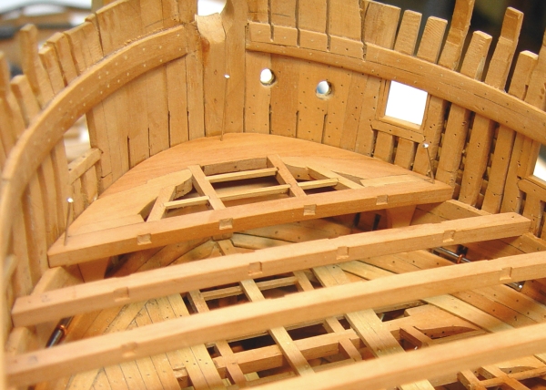
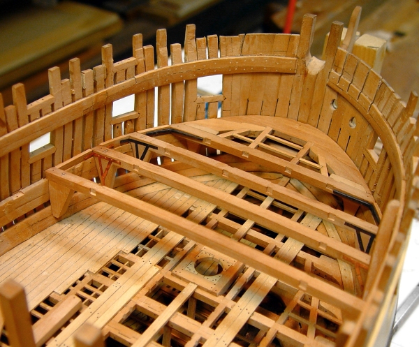
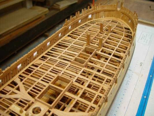
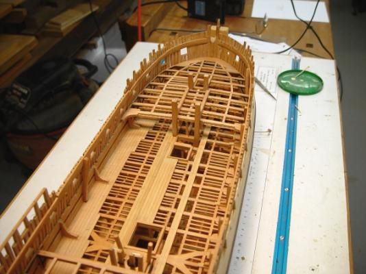
1:60 HMS Naiad 1797 Part 119 –Upper Deck Details – Quarterdeck Beams Posted 1/31/12 There are a lot of details to attend to on the upper deck. The first picture shows the gooseneck installed on top of the tiller. This rides in the circular track, maintaining the height of the tiller and keeping the line in its track. In this picture the port deck planking has been brought out as far as the as yet uninstalled carlings for the half beams on the aftermost five beams. The next picture shows the step of the capstan. The black, square object in the center is the cup, or lower bearing for the capstan spindle. It was bored to fit the spindle. It is made of brass, blackened. Installation of the starboard top riders is in progress as shown in the next picture. The waterways had to be notched for these and the spirketing, the inside of the frames and the quarterdeck clamps all finish sanded before installing these. The areas between the ports on this side will not be planked. In order to line the hawse holes and to finish the details on the inside, the outside planking in the bow area needed to be installed. Although the port side will be left unplanked, the construction of the head structure rests on top of the planking so the most forward part of the hull is partially planked on this side. This is about the extent of this except for a few strakes to take it up to the top of the frames. The hawse holes have been sized but the linings are not installed yet. The next picture shows the four half beams fit into place at the stern of the quarterdeck. I don’t know the purpose of this different framing in this area. Perhaps the captains wanted more structure under their dining tables or desks. The carlings are glued in but the beams are still loose to facilitate tying off the tiller line after the wheel is installed. A lot of the upper deck details require the quarterdeck and forecastle beams to be fit – for example, the upper deck bitts, the bowsprit step, the capstan, partitions, etc. Also, I expect to install the wheel on the qdeck and thread it up before completing the upper deck details. So, the next step was to make all the beams for the qdeck and fcsle. Although these are smaller in section than the beams below, they are still in the range of 35 feet long, so I decided to make all but the shortest few as scarphed beams. The next picture shows one of the later steps in the process. First the tables for the scarphs were cut in wide planks on the milling machine. I believe I described this earlier. They were then glued up using dark glue and tightly clamped. When dry, the piece was clamped in the routing jig as shown above. The making of this jig, which sets the round up of the beams, was described earlier. The same jig was used for all the beams, with the new correct round up being shaped for each set. In the next picture the top curve has been routed and the piece is being marker with the beam depth. The beam is then cut off on the scroll saw and the top of the next beam routed to the pattern. After sawing, the bottoms of all the beams were then sanded to the final depth using the thickness sander. The next picture shows some of the beams. The scarphs reverse at midship, so they need to shaped for the correct orientation. The next picture shows all 40 beams made, numbered, and laid on the hull. Several extras of each type were also made – just in case. It took a couple days to make all these beams. Because the beams are narrower than the earlier beams the machining was slightly different. I used tables that were slightly less deep but the same width and number. Ed


-
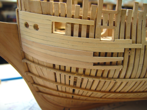
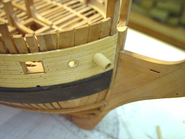
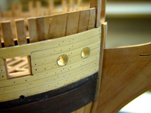
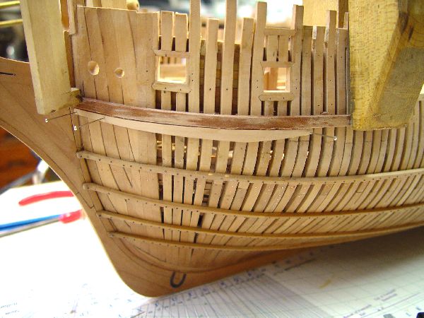
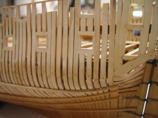
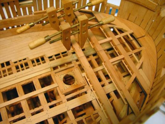
1:60 HMS Naiad 1797 Part 118 –Upper Deck – Hawse Holes, Decking Posted 1/25/12 The hawse holes had bit pilot drilled undersize through the hawse timbers some time ago. It was now time to finish these so that area could be detailed inside on the upper deck. The holes needed to be 14 ½” inside diameter after the linings were installed. I decided to make the lining 1 ½” thick. The first picture shows a Castello tube being turned that will be used to make the lining insert. The hole was drilled first - an undersized 7/32”. Apart from not having a 0.242” drill bit, a tube with a wall thickness of only 1 ½” (.025”) would probably not survive the turning process, so the hole will be enlarged with a file after the lining is safely glued into the hull. After drilling, the outside of the tube was turned to the final size of 17 ½”. The next picture shows the installation of the tubes. The outer tube has been glued into its hole after the hole was carefully enlarged to just fit the tube. The inner tube has been fitted. It will be marked, cut to size and glued in. The next picture shows a lining being enlarged to the ID of 14 ½” using a round file. Diameter gauges were turned so the holes could be checked for size and roundness The next picture shows the completed holes on the starboard side. The tubes were scored to represent a pieced lining. This picture also shows the through bolts around the bridle port. These include the bolts for the gun tackle and the two spirketing bolts through the sill. The next picture shows the hawse hook being installed on the inside. After quite a bit of deliberation I decided to stay with my original plan to omit the inboard planking on the starboard side, except for the structural parts – spirketing and clamps. There will be one piece installed just above the hawse hole to bed the upper deck breast hook, which will be installed shortly, allowing this area to be detailed.. The next picture shows some work on the outside of the hull that needed to be done before detailing the hawse holes on the port side. The port side of the model will be unplanked to expose the framing, but in order to install the head structure some of the planking will be needed at the bow, because the head rails and cheeks fay onto the planking. In this picture the most forward upper piece of the wale has been installed and a section of the black strake is being clamped above it after boiling to set its curve. This area of planking will be extended to the top of the side. It needs to be installed before the hawse linings on this side. The inside hawse hole has been sized in this picture. While this one-step-at-a-time bending-drying-gluing process was going on, work on the deck planking began, as shown in the next picture. The deck planks are 3” thick Castello. They are about 10” wide and they taper down at the stern. The first strake inside of the waterway had to be notched to fit around the top riders. The next picture shows the amount of decking completed so far. Another strake or two may be added on this side, then all taken the full length of the deck. Then there will be open space in as far as the binding strakes. Those will be installed and the remaining area planked to the centerline. The starboard side will be unplanked. There is quite a bit of detailing to be done on this deck, but some will require the beams of the next level to be fitted; so making the quarterdeck and forecastle beams is now on the schedule. Ed


-
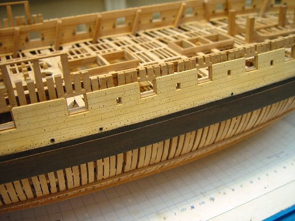
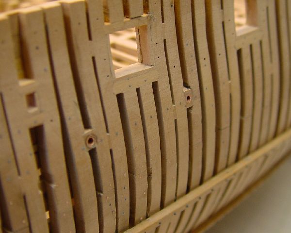
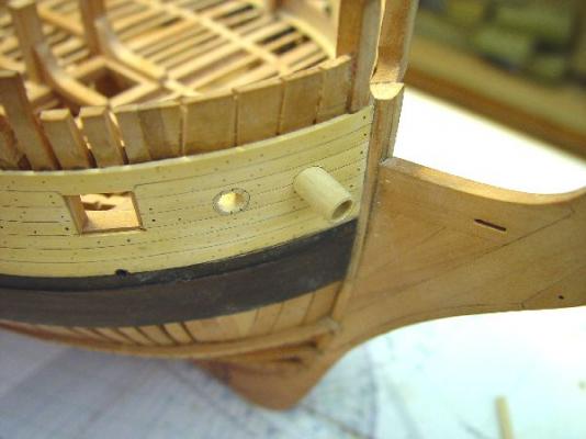
1:60 HMS Naiad 1797 Part 117 –Upper Deck – Ironwork, Scuppers, Riders Posted 1/23/12 This week all the inboard planking of the upper deck was completed on the port side. I haven’t made a decision on the stuff between the ports on the starboard side yet, so work continued on the port side. The first picture shows some ironwork on one of the ports. The tackle eyebolt on the forward side of this port is not yet installed, nor is training eyebolt forward of the ringbolt, but the hole is ready for it. The two spirketing bolts through the through the sill can be seen. The next picture shows some more of this in the area of the captain’s cabins. There was no fancy side paneling in the cabin area but the inboard planking was supposed to be planed smooth. The carlings for the half beams and the half beams themselves are not installed yet. The next picture shows the area at the forward end on the waist. Some eyebolts are still missing. Two of the scuppers can be seen in this picture. The next picture shows more of this side. All the top riders on the port side have been fit up to the planking and reinstalled. More of the scuppers are visible in this picture. The next picture shows some of the scuppers on the external starboard side. On each side there are several 4” scuppers for general deck drainage and two larger 5” scuppers – one for the pump discharge and one all the way forward to drain the manger. These were fashioned from copper tubing to simulate the lead flanges at each end of the pipe. They next picture shows the detail on the unplanked exterior port side. The copper tubing was fit into square stock and then notched into scores between the frames. Inside and outside parts were made separately. Since the exposed port side has not been final sanded at this stage the scuppers have not been blackened yet. The last picture shows current progress looking aft. Ed


-
1:60 HMS Naiad 1797 Part 116 –Upper Deck – Quickwork Posted 1/17/12 The first picture shows some of the last work on the upper deck spirketing installation at the bow. The piece on the port side is being glued – held in place by pins. The piece on the starboard side was boiled and clamped to set the bend. In this picture it has dried and is ready to be unclamped, sanded and glued in place. The next picture shows work on the stuff between the ports. This work proceeded concurrently. This thinner planking is Castello, to give some contrast with the pear spirketing and the quarterdeck clamps. The three strakes are pinned in place for gluing. Only the port side will get this planking. I’m trying to keep up on the outside of the hull. The next picture shows some work done concurrently with the inside work. In this picture the upper deck lodging knee bolts have been installed in a long fair line on the outside of the frames. Most of the hanging knee bolts were installed earlier. Also, the holes for the spirketing bolts through the sills and the bolt holes for the gun tackle ironwork have been drilled on both sides of the ports – all the way through from the inside. The next picture shows a test of one of the ringbolts on the inside. The eyebolt has an inside diameter of 2” and ring 4 1/2'”. These will be inserted halfway through the hole and glued with CA. These are blackened copper. Monofilament will be used to simulate the outside of these bolts. The next picture shows the first group of these fittings installed. The sequence here was to install the treenails, fully sand the planking, fit and re-install the topriders, then install the ironwork. I am doing this one section at a time, working forward – to break up the monotony of treenailing. This picture also gives a good view of the two spirketing bolts through the sill. The next picture shows the area of the upper deck finished so far. And the next picture shows the work forward of this – the treenailing. These have yet to be leveled off and sanded. In doing these I have to remember which holes will get bolts and leave out the nails. I’ve had to redrill a few so far. In this picture the waterway has been cut to receive the riders. Also note the step up from the end of the quarterdeck clamp to the string in the waist, just where the Qdeck ends. A few more days work should see the end of the inboard planking on this deck. Ed


-
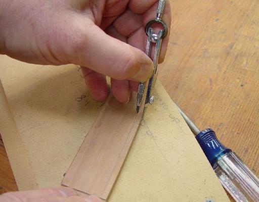
1:60 HMS Naiad 1797 Part 115 –Upper Deck Waterways, Spirketing Posted 1/10/12 After the last posting, all of the remaining ledges of the upper deck were installed. The framing of the deck was then leveled out where needed and the filling pieces at the side were pared down level with the tops of the deck beams. The next step was to install the waterways. In the next picture stock is being shaped to make these. The waterway is thicker under the first strake of spirketing, tapering down in a curve to the thickness of the deck planking. The machining of this shape was done in two steps. First the concave curve was cut with a round ended milling cutter. Then the second cut was made to level the end that would abut the deck planks. The simple jig in the picture was made to guide the pieces through the cutter. The next picture shows one of the forward, curved pieces of waterway being fit. The flat piece of Castello was shaped to fit the curve of the frames using a disk sander. For curved pieces like this I do not bother with card forms or spiling. The shape was roughly drawn on a rectangular piece of wood and then progressively sanded to shape until a tight fit was obtained. The width of the piece was the marked with a small compass, cut on the scroll saw, then sanded to shape. A different jig was used to machine these curved pieces. The next picture shows the waterways installed. This picture also shows the installation of all the ledges. On the starboard side, the joints are cut, but the actual ledges are left out for visibility into the lower decks on that side. Next is another picture taken further aft. The top riders were all removed before installing the waterways. The waterways will have to be cut out to permit these to be installed later. This seemed easier than trying to fit the waterways and the rest of the interior planking behind the riders. Before moving to the spirketing, the port gunport linings had to be installed. The next picture shows a couple of these after the linings were faired down with 120-grit paper. There is a bit of lens distortion here which makes the line of these last three ports appear humped. The outside of these port frames will be finish sanded later, since they will be left exposed. The notches in the frames below the ports are the openings for the lower deck scuttles. The next picture shows the spirketing on the port side mostly installed. This comes up to the tops of the port sills and its upper edge is dubbed off to be horizontal at the height of the linings. The large block is holding one of the guy wires that keep the hull in place. These were removed to work on this in that area, then replaced. The next picture is a closer view of the aft sections of spirketing being installed on the starboard side. The spirketing on the lower deck is installed with anchor stock configuration. This was spelled out specifically in the three contracts from the Naiad period that I am using. This was not specified in any of those for the upper deck, so these are being installed as straight planks. The pins are forced through slightly undersized hole using pliers to hold them in place when gluing. The tops of the planks were dubbed off using a Stanley number 93 plane with the stock held in a wide vise. The last picture shows the run of spirketing on the port side, pinned and glued in place. While these pictures were being taken, the curved section at the bow was being clamped to shape in place after boiling. The next step will be to plank between the ports on the port side only. The top riders can then be reinstalled. Ed


-
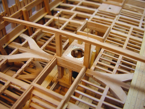
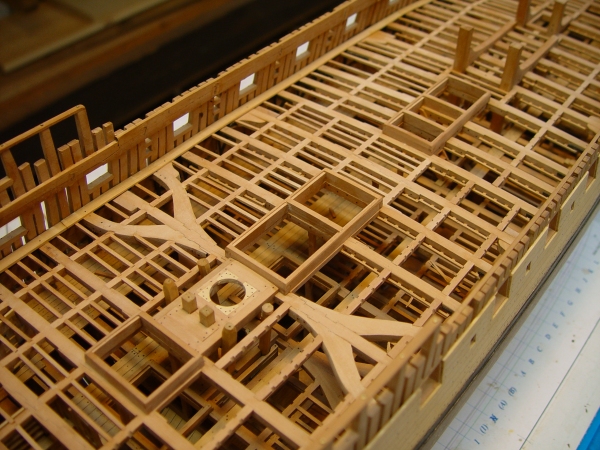
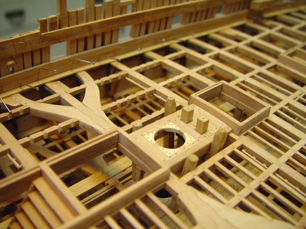
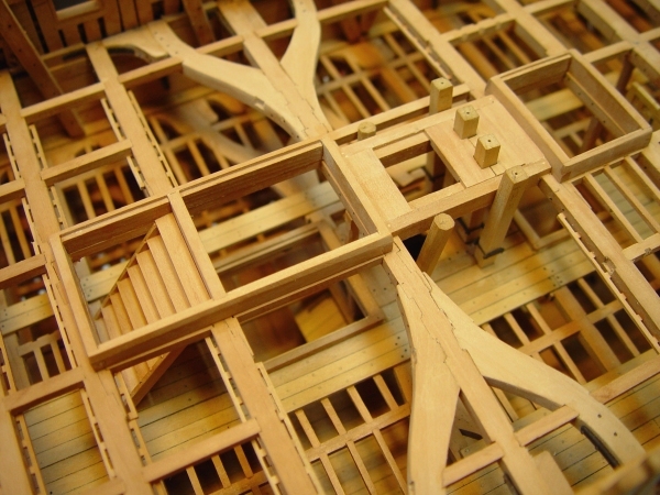
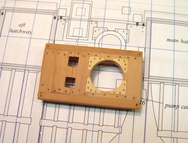
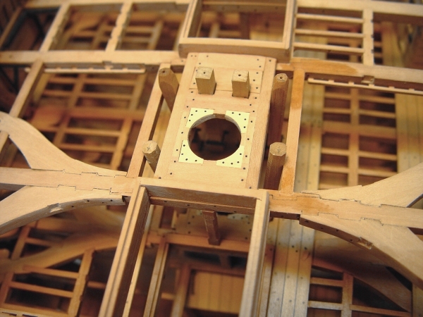
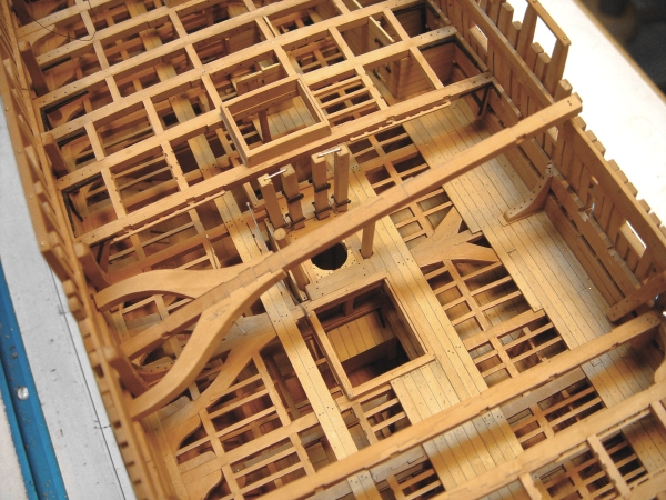
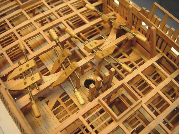
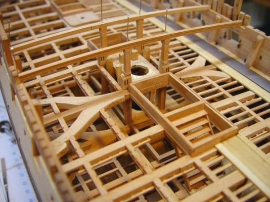
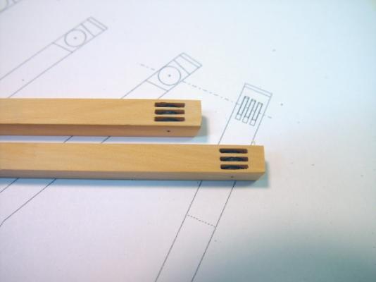
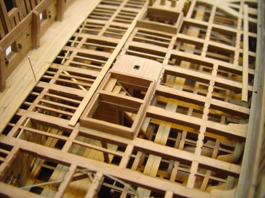
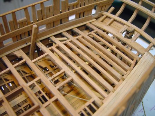
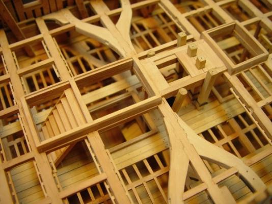
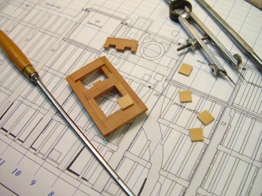
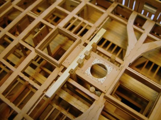
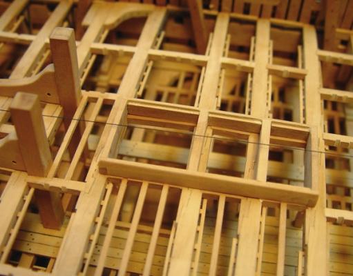
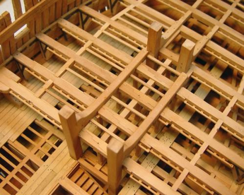
1:60 HMS Naiad 1797 Part 114 –Upper Deck Main Partners Posted 12/31/11 In the last post the central beam and beam arms were installed. The next step was to fit the main mast partners, the main hatchway carlings and hatchway details. The first picture shows this area. The hatchway coamings and headledges for the main hatch and main companionway, including the steps, are installed in this picture. Also, the cross chocks of the partners are set into the rabbets in the large sized partner carlings, which are fitted but not glued. At this stage only the fore and aft chocks are glued to to the carlings to allow the assembly to be removed to the bench for detailing. The cross chocks around the pump casing have been cut to fit but are loose at this stage. The next picture shows the assembly removed for further work. In this picture the central cross chock and fillers on the sides of the openings have been glued in. The outline of the corner chocks has been marked out and one of these is set over its location so the rabbet lines for it can be marked. Rabbets were then let down and the cross chocks inserted. These are made in two parts, top and bottom, to avoid having to cut rabbets in these very small pieces. The finished assembly is shown below. The cross chock section just aft of the openings for the pump casings is still loose in this picture, to allow the assembly to fit over the casings. In the next picture the installation is complete. The four Cole pump casings are now permanently glued on to pins in the well and all the sections of the cross chocks and the whole assembly is glued in. The two elm tree pump casings, for some reason are too short, so these will be replaced. The two pump carlings, outside of the partners, are also installed in this picture. The next picture shows some preparatory work being done to get ready for the pump cisterns. In this picture the cross piece of boxwood has been fitted around the pump casings. This will then be slit into two pieces that will then be edge glued to form the floors of the two cisterns. The next picture shows the two pieces joined and fit over the casings. The blank for the cistern floors has been made in one piece to help assure that the two cisterns are precisely aligned and not affected by misalignment of the four casings or due to differences in the cutouts. The next step will be to rip this piece down to the bottom width of the cisterns then separate it into the two separate floors. I do not expect the cisterns to be watertight. The last picture shows the state of the upper deck on the last day before New Years eve 2011. The thread on the centerline has been a big help in keeping things centered on this deck. All the upper deck carlings are installed at this stage. The long strips of Castello lying on the deck are blanks for the waterways. These will be milled and installed on both sides as was done on the lower deck. The inside planking of the port side can then begin. Happy New Year everyone. Ed


-
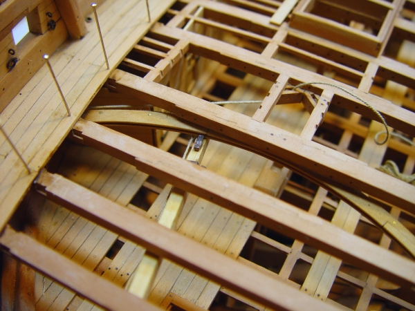
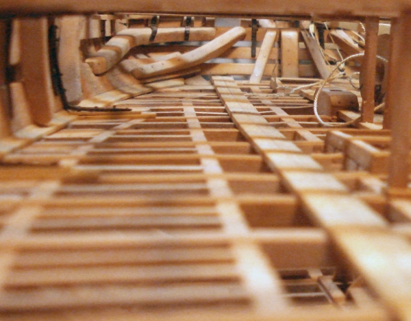
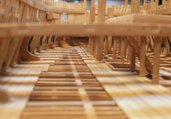
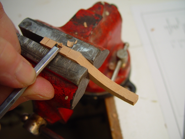
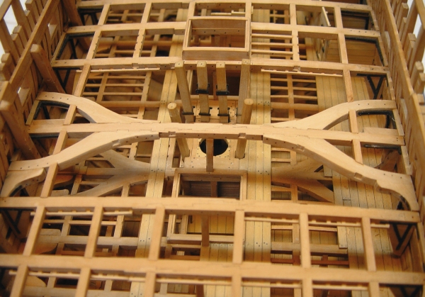
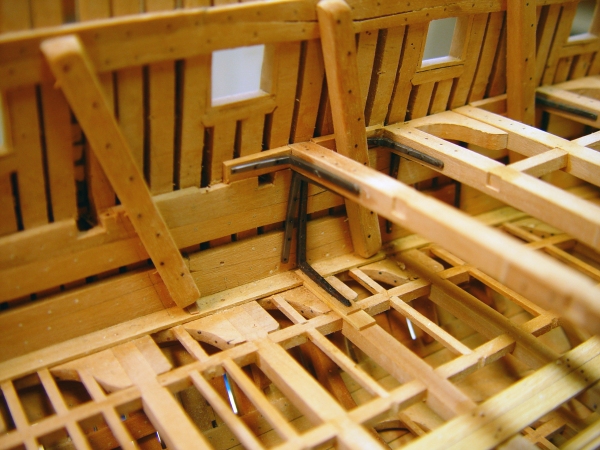
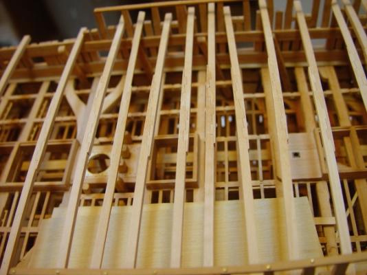
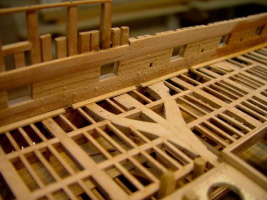
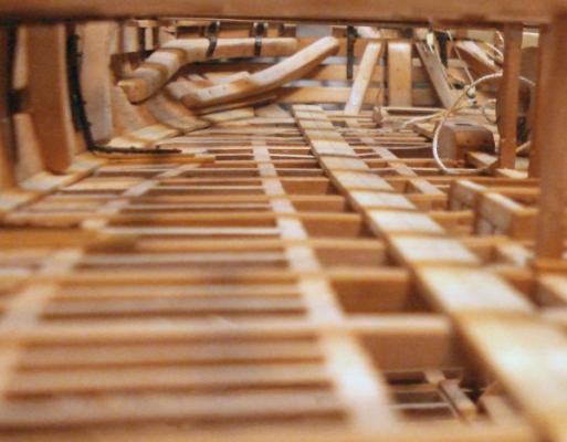
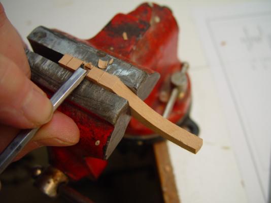
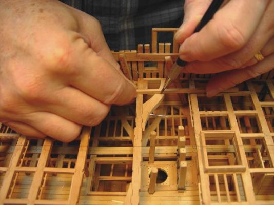
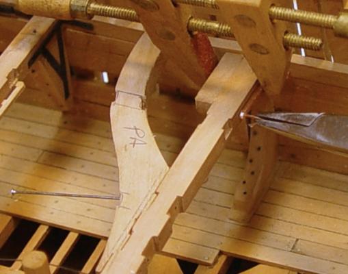
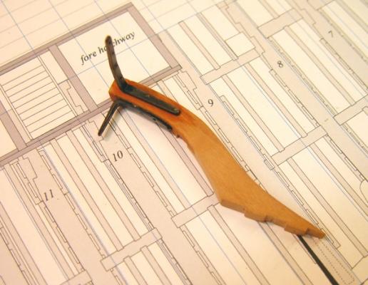
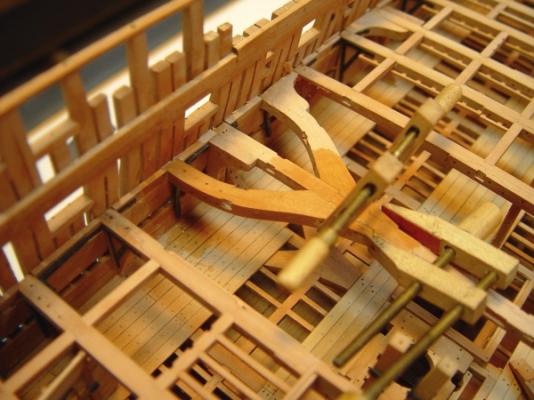
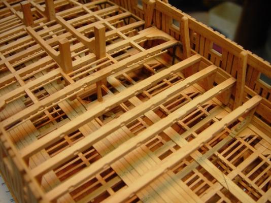
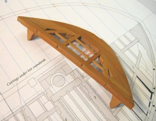
1:60 HMS Naiad 1797 Part 113 – The Last Upper Deck Beam Posted 12/19/11 The last beam was the most complex and most interesting to install, but first two pictures on the lower deck – the last opportunity to put the little camera into the gap between beams. Depth of field isn’t great, of course. This is looking aft on the lower deck, giving a nice view of the wing transom knee, sleepers and sternson knee. The rope is waiting to be threaded up through the wheel and back through the tiller sweep. Port side looking forward. The small forest of pillars to the right, between the bitt pins, supports the fireplace. Finally, the last beam. This beam, number 16, is just aft of the main hatch and just forward of the main mast partners, so it is quite a distance from its two neighbors (Beam 15 is still out in this picture.) The beam is reinforced with two sets of beam arms just like its lower deck counterpart. The beam could not be prefabricated with its arms. The problem is illustrated in the picture. Getting this beam in even by itself required some deflection because of the tapering in of the sides. There was no way it could be set with even one of the arms attached – well, maybe one. There are a variety of wood and iron knees used in this assembly and they will be described below. We do not know exactly how these were done on the actual Naiad, so the mix is speculative. Getting a workable sequence for fitting all these knees and assembling the beam in place was an interesting problem. The first step was to make the beam arms and the tabled scarphs to the main beam. The picture below shows the basic pieces. After cutting the basic shapes of the arms, the scarphs were marked out while the pieces were fit in place on the model – not from this drawing. The scarph tables were all cut manually. One of the steps is shown in the next picture. The joint lines were first cut with a razor saw, then pared out with the chisel, then dressed with a file. I could have done these on the mill, but this way is easy and avoids set up on the mill In the next picture, wood hanging knees are being glued to the ends of the beam. The beam is pinned but not glued. It was then removed to level the tops of the knees and install the hanging knee bolts through the beam. It was then permanently glued in and its pillar installed. The lodging knees for this beam are iron and will be shown later. The beam arms were then pinned in place so the mortises for the carlings could be marked out as shown in the next picture. A long strip of carling stock is being used to mark the mortises and assure the overall line of carlings is straight. The mortises will then be chiseled out on the bench. The next picture shows the wood lodging knees on the forward arms being glued to the arms. The arms are only pinned in this picture. The hanging knees for these forward arms are iron. The next picture shows an iron lodging knee for the main beam being installed. The iron (copper) knee is clamped to the beam. The hole for the first bolt has been drilled and the bolt is being forced to the bottom of the hole with pliers in this picture. It will then be cut off above the surface of the knee and hammered in, expanding the head. The other bolts will then be installed including one into the frames. The fore and aft arm of this knee is short because there is a rider to be installed just forward of the beam. The next picture shows an aft arm assembly about to be installed. This arm (upside down) has two iron knees that have just been blackened after bolting. The wood is still wet from the sulfur solution being washed off. The next picture shows a beam arm on the port side being glued in place. These were done one at a time with their knees installed. With both arms permanently fixed, the bolts through the beam were installed through holes drilled earlier. Bolts were then also installed in all the iron knees. Holes were predrilled for these while the pieces were still removable. The last picture shows the completed beam installation. The outer tiers of carlings, except for one piece, have been installed in this picture. All the upper deck beams are now installed. Time to take a Christmas break and ponder the next move. Best wishes to all for the holidays! Ed


-
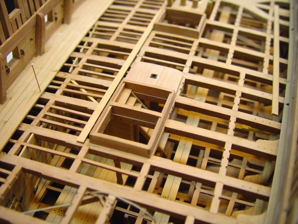
1:60 HMS Naiad 1797 Part 112 - Upper Deck Beams – Hatchways Posted 12/2/11 Work continued this week on the upper deck beam installation, which is now becoming routine – fit the beam, make and fit the wood knees or chocks, bolt on the iron knees, set the beam install the pillar, then the hammock battens and then the carlings. The first picture shows beam 9 installed, the first beam aft of the main bitt pins. The next four beams, 10 to 13, are temporarily positioned with the filling pieces between them installed at the sides. The next picture shows beams 10 to 12 installed. I have been installing the carlings and in some cases the ledges with the beams, partly to break up some of the monotony but also to allow some of the between deck structures to be installed, like the ladderway aft of the fore hatch shown in this picture. The next picture shows beam13 installed and the next two laid in place. Beam 13 has wooden hanging and lodging knees – a small change of pace. A further diversion this week was the installation of some of the coamings and head ledges for the hatchways as shown in the last two pictures. These coamings and head ledges rise 13” above the deck at this level. To do that they need to be 16” high, considering that the deck planking is 3” thick. The coamings are rabbeted for the grating ledges and the corners are made with locked lap joints. The sides are bearded at the top 1” and the corners will be rounded above the level of the deck. The intermediate cross pieces are set in scores on the coamings. All these will be bolted to the beams. The next picture shows the hatchways further aft. The single large opening to the right is the aft hatch, which, like the fore and main hatches, goes all the way down into the hold. The double hatchway to the left will have a ladderway in the forward opening. The aft opening is a hatch only to the lower deck. The step for the capstan will cover the opening just ahead of this hatchway structure. Ed


-
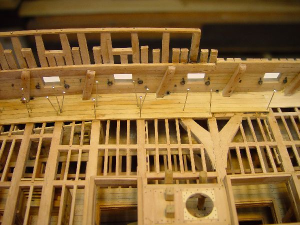
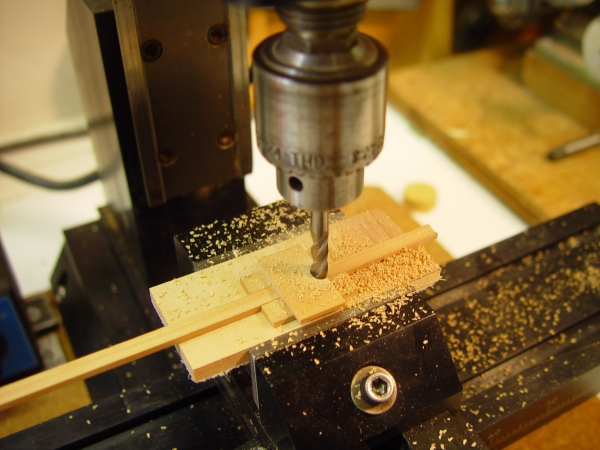
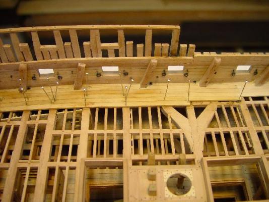
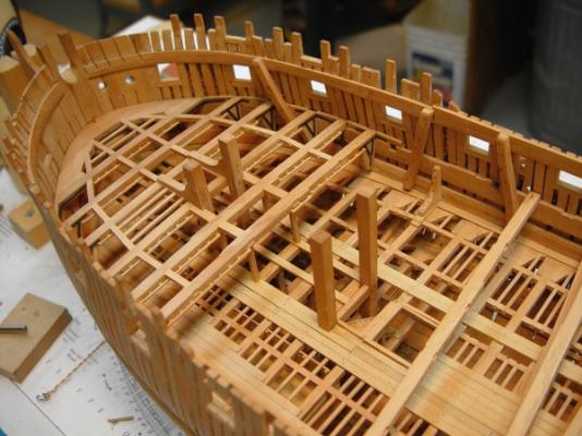
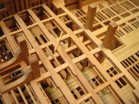
1:60 HMS Naiad 1797 Part 111 - Upper Deck Beams – Riding Bitts Posted 12/2/11 After the last post there were some questions about the hammock battens. The first picture shows how they were milled on a wide piece before being slit off on the circular saw. This piece is about 6“ thick allowing for a 3” square batten with three inch blocks to offset it from the beam. A 3/16 inch square end mill was used and advanced ¼ inch after each pass. Two of these pieces were needed. The next picture shows how the sliced off battens were fastened. I found that these were easier to glue on and clamp after the beams were installed. They are flush with the bottom of the beams and held with clamps after gluing. After the first four forward beams were installed the riding bitts had to be addressed with the next set of beams. The first step was to install the forward bit pins against the aft side of beam 4 and the same beam on the deck below. The main issue with these is that they be equidistant from the centerline and vertical. The thread line seen in most of these pictures was used constantly. The next picture shows the forward pins and their standard knees installed. The knees of these forward pins form the sides of the rabbet for the cross chocks that make up the mast partners. The carlings under these form the supports under these chocks. The rest of the mast partners assembly will be installed later. The next picture shows a top view of this with Beam 5 installed. Beam 5 has plain iron knees because of its proximity to the first ridersnotshown), which leave no room for the tabs on the plate knees. Beams 5, 6, and 7 have double pillars supporting their centers. These beams supported the galley stove and its heavy layer of refractory brick or stone, which was used to insulate the wood structure from the hot stove fireboxes. It was probably important that this structure be very rigid to keep the brickwork from breaking up as it flexed. The next picture shows a beam being “jacked up” or “sprung” so it can be popped into place. If the beams are cut to just fit between the frames, this bending is necessary on this deck because the tumblehome of the sides prevents the beam from fitting above its notch in the clamp. Having the beams fit tightly, apart from the aesthetics, is a good idea because it makes marking out the centerlines and carlings more accurate and helps maintain straight lines. This beam had the hammock battens installed on the bench, but with this heavy handling it is easy to break them – one of the reasons I later decided to wait for the beams to be installed before adding these.. The next picture shows beams 5 and 6 installed. In this picture the wider carlings under the bit standards are also being installed along with each beam. I made these flush with the beam tops like the other carlings, In practice the bitt standards were let down 1 to 1 ¼” on the beams, which would require the carlings to be lower by that amount and the ledges to sit above the tops of the carlings by that amount. These .02” scores will be barely discernible on this deck so I took the simpler approach. The next picture shows the carling under the fireplace – another interesting bit of construction. This long 9” square carling is scored and let up about 2 “ on the underside of the beams. The space between the top of this and the undersides of the ledges was filled with fir filling pieces. In the picture the fillers and the ledges are installed in the forward two spaces. In the third space only the filler has been installed with the ledge still lying loose. The fourth space has no filling piece as yet. Beam 8 is securely fastened to the aft bit pins with two bolts. It is also fitted with wood hanging and lodging knees. The beam was installed first with the ends fastened securely with its knees and bolts. The starboard bit pin was almost perfectly positioned, but its partner was leaning a bit to the center. The starboard pin was then glued and bolted to the beam. When this was secure the port pin was then forced slightly to the side to make it right, wedged in place at the beam score, glued, clamped and bolted. The deflection was slight but the small misalignment was very noticeable. The next picture shows the aft bitt standards after installation. These are bolted through the beams and through the wide carlings below. This picture also shows three pillars under the fireplace carling for additional support. This final structure should have no problem supporting my model stove, no matter what it is finally made of. The last picture shows the overall model at this stage and the amount of upper deck structure remaining to be installed. The work from this point going aft is pretty straightforward up to the last remaining beam with its two curved beam arms. All of the remaining plate knees have been etched out. The first few were .005” thick, but all the subsequent ones are made from .01” copper. They do not look much different but they are a bit more resistant to handling damage when the beam assembly is being taken in and out.. Ed


-
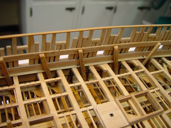
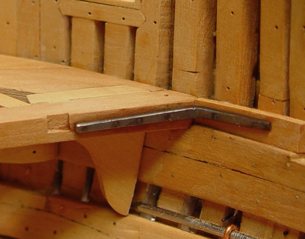
1:60 HMS Naiad 1797 Part 110 - Forward Upper Deck Beams Posted 11/21/11 After installing the aft upper deck beams as far as midship, I moved to the beams in the bow so that beams are being installed smaller beams first. This facilitates the maneuvering of succeeding beams into place and also the installation of the lodging knees, which were always on the midship facing side of the beam. The first piece to be made in the bow was the upper deck hook. This was cut and fit against the hawse timbers then removed so it’s assembly with beam #1, the ekeing pieces and the beam’s hanging knees, carlings and ledges could all be done on the bench. The first picture shows the finished assembly. Beam #1 has wood hanging knees and angled iron lodging knees. The next picture shows the installed assembly. You will notice in this picture that the forecastle clamp has been sawn through in four places because I forgot to cut the air gaps between hawse timbers before installing these clamps. This piece and the same piece on the port side will be replaced. The next picture shows the iron lodging knee on the starboard side of beam #1 being bolted into place. After marking and drilling undersized holes in the beam, the drawn copper wire is being forced to bottom in the hole with pliers. It will the be clipped off just above the surface and peened over with a hammer. The next picture is a scary closeup of the finished knee taken right after chemical treatment. That’s a three-penny finishing nail at the bottom of the picture holding a copper guy wire. The picture also shows a black monofilament bolt that has gone astray and missed the beam. Isn’t magnification great? In the next picture beam 2 is installed and beams 3 and 4 are being fit up. The next picture shows the first two beams with their carlings and hammock battens installed. These battens provide spaces for hammocks to be hung on the prescribed 14” centers. Hammocks would have been slung between battens on every other beam. The battens on the aft side of beam 2 will pair up with those on the fore side of beam 4. Most beams will have battens on both sides, but not those at the ends. These forward hammocks would probably have been in the sick bay. There will be about 250 hammock spaces on this deck. Everyone slept on this deck except the captain and the few junior officers with spaces on the platform below at the orlop level. Things on this deck were a bit tight to say the least. The last picture shows the extent of upper deck beams installed so far. Time to photo-etch some more plate knees. Ed

-
Thanks, runner and Len for your comments. Len, on the shipping costs you should check with Seawatchbooks.com. I do not have that information. There is an appendix in Volume I of about 30 pages discussing drafting model plans from Admiralty drafts using CAD based on the drafting methods used by the original surveyors. However, it is not CAD tutorial. Software differs and I wanted to focus on the drafting. A CAD manual would be larger than Vol I. I did not address 3D drafting. There is a section on fairing out the lines at the stern where the body plan and the waterlines are not sufficient in themselves to establish the final lines. Lofting of frames is covered in depth based on body lines developed by original methods. The appendix is my practicum. If I were to write another one, I would have to give up either eating or sleeping. Maybe someday. Ed
-
Thank you Christian and Greg, Yes, photo-etching is something of an art form, but for me it doesn't come close to trying to make soldered brass stay black, I have finally surrendered and painted Naiads stack - after watching white powdery corroasion develop over a month or two - four times - with every washging idea I could come up with. With photo-etching, the metal is either there or not there. Ed
-
HMS Victory by EdT - FINISHED - 1:96 - POB
EdT replied to EdT's topic in - Build logs for subjects built 1751 - 1800
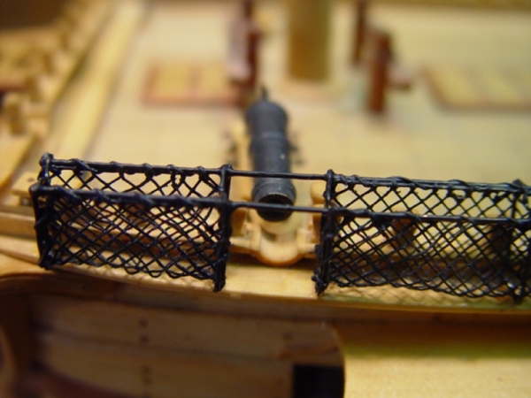
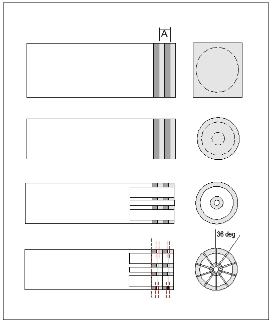
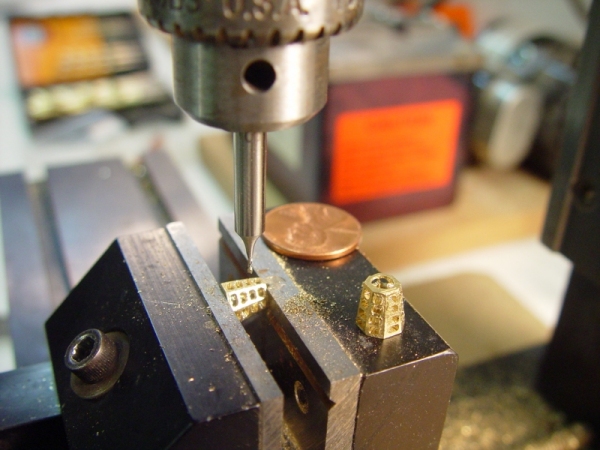
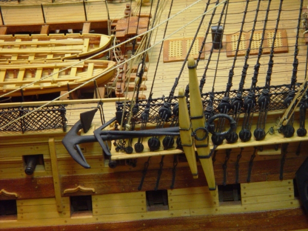
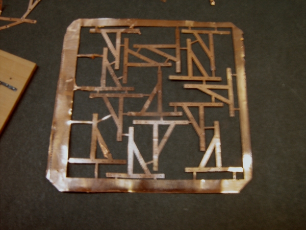
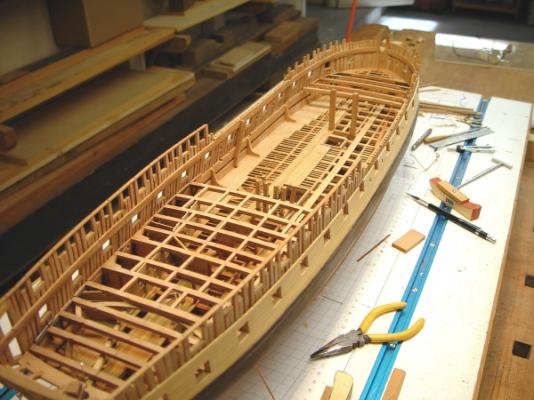
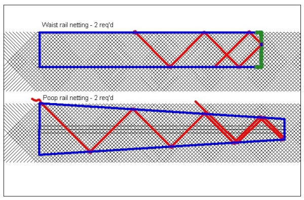
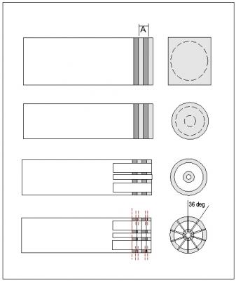
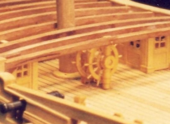
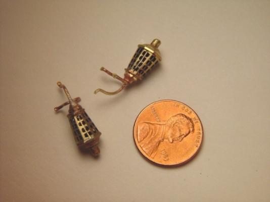
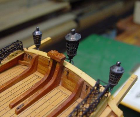
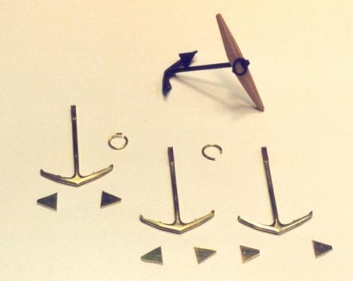
HMS Victory 1:96 Scratchbuild Project Part 9 – Deck Details 2 In this part I will focus on four modeling processes – the hammock nettings, the ships wheel, the lanterns and the anchors. Hammock Nettings Victory had hammock nettings on just about every rail, perhaps because they had to accommodate the hammock bags of 800 crew, but also, I am sure, because the more protection from flying fragments or splinters in battle the better. Anyway, there are a lot of them. They are of different sizes and those along the poop deck rail are tapered, being shorter at the aft end. If you look at pictures of the real ship, these nettings droop and sag as you would expect rope netting to do, so using rigid screen, for example, was out of the question. The method I used was to weave fine cotton thread on a 6” mesh grid to fit the shape of each of the sections of netting, then fasten these to the ironwork u-shaped hammock cranes that were fashioned from brass wire soldered together. The hammock cranes were straightforward. On the real ship they were square, but because of the scale, I simply used stiff brass wire. This was bent into the u-shapes and a short piece was soldered to the bottom for insertion into the rail. Then longitudinal lengths of wire were soldered on at the tops to tie them together and provide support to which the netting could be lashed. Short pieces of wire were soldered across, between the tops of each crane. These assemblies were trial fit into place on the rails before adding the netting. The nettings were a more difficult problem, though once solved the only issue was the tedious job of making them. First, a CAD drawing was made of the layout of each unique section of netting. An example for two of the sections is shown below. On this drawing the diagonal lines are spaced 6” (1/16”) apart and the boundary of the net is drawn on this grid. A copy of this was the placed on a piece of Homosote board and a piece of wax paper placed on top of that. Pins were inserted at the four corners of the section and at the intersection of each grid point with the outside line. A piece of fine copper wire was then strung around the four corners and twisted taut. The following picture will help describe this. In this picture the blue line represents the fine wire around the outside and the green closely spaced dots the location of some of the pins. When all these pins were hammered into place, fine cotton thread was tied off on one pin and then woven back and forth as shown by the red lines above. At each pin the thread was looped under itself and around the wire and then woven under and over previously laid thread alternatively to form the final woven mesh. A small curved sewing needle was very helpful in doing this endless over and under weaving. When the section was completely woven, the mesh was pulled up on the pins about 1/8” to get it off the waxed paper. It was then coated with shellac to stick it together. This was done in several dilute applications to avoid the shellac filling in the holes in the mesh. If the mesh is bridged with liquid this can be removed easily with a Q-Tip. When dry and with all the weave secured, the pins were carefully removed leaving the completed section of netting. This was then folded, inserted into its wire frame and secured to the top longitudinal wire with fine thread. The assembly was then given a coat of flat black enamel to deaden the sheen of the shellac and blacken the wire, an exception to my no paint philosophy. When finished, the assemblies were fit into the holes in the rails and given a small drop of CA glue. The tops were then bent to the sag seen on the real ship. Some of the photos in Part 8 show these nettings well. The picture below is a close up of some of this on the port forecastle rail. These netting structures need to be fairly strong because it is impossible not to abuse them somewhat when doing later rigging, and once the mesh is in place they cannot be repaired with solder. At this point I will mention a tool that was made to deliver very small drops of CA. Most applicators yield drops that are too large for most of this work, especially later when used for rigging. I use a very thin CA, which I buy in 2 oz. Bottles. I do not use the applicator tip. Instead the bottle is placed open in a safety holder made from thick wood with a hole bored to the diameter of the bottle. A 4” wide base is put under this. You do not want open bottles of CA free-standing on your workbench. I then dip an applicator into the bottle. The applicators I use were made from a piece of .020” brass stiff wire. A fine slot about ½” long is sawn into the end of this wire on the centerline with a fine jeweler’s saw. The end is then filed round and the two parts of the tip bent slightly into a shape resembling an old style drafting pen. This then holds a very small drop of cement. At least two of these are needed, because they quickly become coated with CA. The spares are kept standing upright in a tall closed jar with about 2” of Acetone in it. This quickly dissolves the CA so that a clean applicator is ready when needed. After awhile the Acetone needs to be refreshed. Keeping the jar closed is important, first because Acetone is hazardous from a health and fire standpoint, but also the vapors in the jar help clean the applicators. The Wheel The ship’s wheel is one of my favorite parts on the model, but unfortunately it is almost invisible tucked in under the poop deck and behind the binnacle cabinet. It is modeled in boxwood and is a pretty close replica of the original considering its small size of about ½” in diameter. The assembly consists of two wheels each with the standard 10 spokes. The steps to make these two wheels and the central spindle so that all the holes for the spokes were properly aligned is shown in the following drawing. The first diagram at the top shows a square block of wood slightly larger in width and breadth than the finished wheel diameter. This is made long enough to eventually fit into a lathe chuck. To one end of this, thin pieces of boxwood are glued with alternating grain direction. In the diagram the darker grey is end grain, the light grey side grain. This lamination will yield strong wheel assemblies and mimics the real construction to some degree. “A” is the distance between the centers of the two wheels and the joints between wood layers must be located precisely on this dimension. The dashed line in these pictures represent the cuts to be made next. This piece is then setup in the lathe between centers and turned to the outside diameter of the wheels as shown in the second diagram down. This now round piece is chucked in the lathe. I used a three jaw centering chuck. A center hole is then drilled to take the spindle axle and the wood between the spindle and the inside diameter of the wheel is removed with a very small lathe tool. The bottom view shows the final steps. The ten holes for the spokes are drilled 36 degrees apart around the outside diameter, all the way through into the central spindle, before the wheels are parted off. The distance between these holes can be set off with dividers. It is essential that the piece be set up for drilling so that the drill is perpendicular to the tangent of the outside diameter at each point. If not, the wheel spokes will not be radial and that is one of the main goals of this process. An index mark is placed on both wheels and the spindle to assure correct alignment later. Finally the wheels and the spindle are parted off where indicated by the red lines. This must be done carefully to avoid breaking the wheels. The excess at the end was taken off by turning it down on the lathe. Then the two wheels were parted off manually with a fine blade jewelers saw and the sawn surfaces were sanded flat and smooth. Spokes of the correct diameter can then be inserted to assemble the three parts. This can then be mounted on an axle and supported by appropriate pillars. The best picture I still have of this assembly is shown below. Lanterns There are four lanterns on Victory, three at the stern and the Admiral’s lantern mounted on the aft side of the main top. I felt these were too small to be made in wood and decided to make them of brass to be chemically blackened. Making the main body of the lantern with its paned windows was the most challenging part. The lanterns are octagonal with the fore face of the bottom aligned vertically with the fore face of the larger top, so they basically slant aft. Each face has two vertical rows of panes, slanted down its centerline. The forward faces have no panes. The tops and bottoms have a curved shape on each octagonal face segment and each lantern has a small octagonal chimney on top. There is one large central lantern at the stern flanked by two smaller ones. The lantern in the maintop is quite small and eventually was done as a solid chunk of brass. First the outside shape of the lantern was filed into a small block of brass. Extra length left on this was then clamped securely in a milling vice and the inside of the lantern was hogged out on the milling machine. In the next step, shown below, the bodies have been cut down to final length and the window holes are being milled out with a 1/32” milling cutter. These were milled across the whole face, since the cutter and my files were too large to make individual small panes. After this milling step, the holes were squared as much as possible with a very small (1/32” sq.) jeweler’s file. I have had two of these for years, one square, one round, but have never seen them on the market since. I try not to break or lose them and save them for jobs like this. After squaring the holes slots were sawn vertically down the center of the faces to take the center mullions, which were made from brass wire and were soldered into place. Two of the completed lanterns with their mounting brackets are shown below before blackening. The last picture shows the three lanterns mounted at the stern. Anchors Victory had several anchors of various sizes. There were, of course, the two main bower anchors, which were attached to their hawsers and made fast to the side below the catheads ready if needed.. In addition, there were two spare bowers lashed to the side at the aft end of the forecastle. One of these had the smaller sheet anchor lashed to it for storage. Lastly there is the kedge anchor, which was stored on one of the mizzen channels. The bower anchors were huge, 21 feet long and weighing almost 8400 pounds. Making them with eighteenth century technologies with only muscle power forging was a major feat of engineering. For the model all these were made from brass and blackened chemically. The picture below was taken during fabrication. At the top is a finished bower anchor and below are the parts of its three mates. The shaft is square at the top so was turned from a square brass rod along the middle section. It was left square at the bottom to fit into a notch that was let into the piece that was cut from 1/8” plate in the shape of the arms. These were silver soldered to the shafts and filed to the rounded shape as shown. The triangular flukes were cut from 1/16” brass sheet and silver soldered to the arms. Each was filed to the correct final shape. The rings were inserted into holes drilled in the square tops and then silver soldered together. After blackening, stocks made of boxwood were and fitted, square brass metal bands installed (not shown above) and the ring was “puddened”, that is, wrapped with thread. The picture below shows the spare bower and the sheet anchor, both lashed to the starboard fore channel with the fluke of the bower resting in a special block for that purpose on the planksheer. Silver Soldering The last thing I would like to mention in this part is silver soldering. I have referred to it a number of times and there is a great deal of it to be done in the fabrication of all the ironwork on this model, some of large pieces, like the anchors, and some of very small pieces, like eyebolts and small diameter rings. This can be a difficult technique to do reasonably well, let alone master, and many shy away from it. I had a lot of difficulty with it until I got a small propane torch and the right soldering materials. A small propane torch is inexpensive and very adequate for this type of work. I have a small dual gas high temperature torch which was expensive and uses expensive fuel. This is not needed. However, I found that the right soldering materials are most important. I started with brush on fluxes and wire solder, which had to be cut into small pieces which always seemed to be too large or resistant to being attached to the work. All these problems ended when I went to syringes of powder solder in flux, which can be injected directly where needed in very small amounts, easily controlled. Toxic and non-toxic, high and low temperature varieties are available. I purchase mine from an online jewelry-making supplier. They are inexpensive, last a long time, and for me at least, have made the process simpler and if fact manageable. They have also helped produce higher quality work, avoiding large blobs of solder on the final piece. In Part 10, the last section on deck details, I will discuss the modeling of the planked ships boats, two of which are partly visible in the above picture. Please stay tuned. Ed Tosti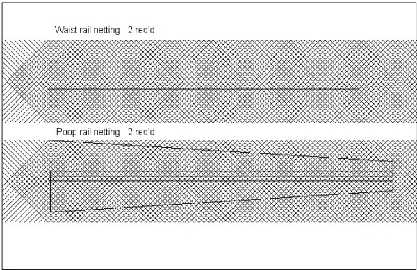


- 57 replies
-
- 10
-

-
USF Confederacy by Rustyj - FINISHED
EdT replied to Rustyj's topic in - Build logs for subjects built 1751 - 1800
Beautiful job, Rusty. Ed -
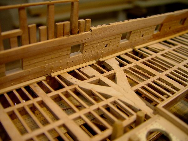
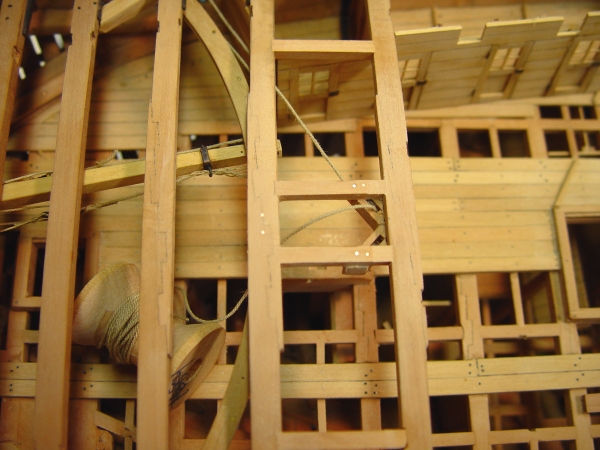
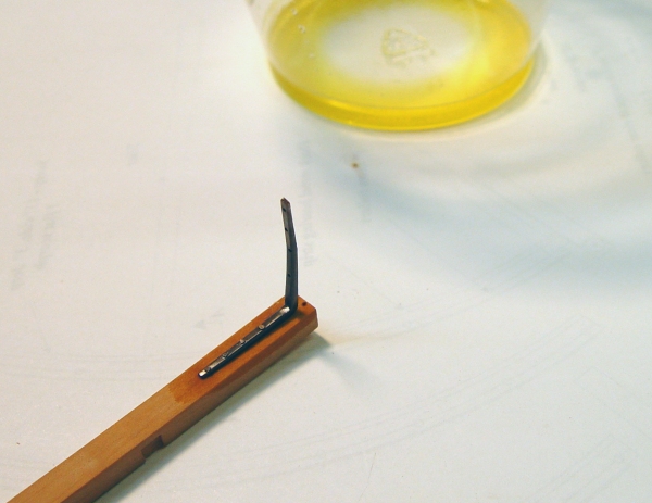
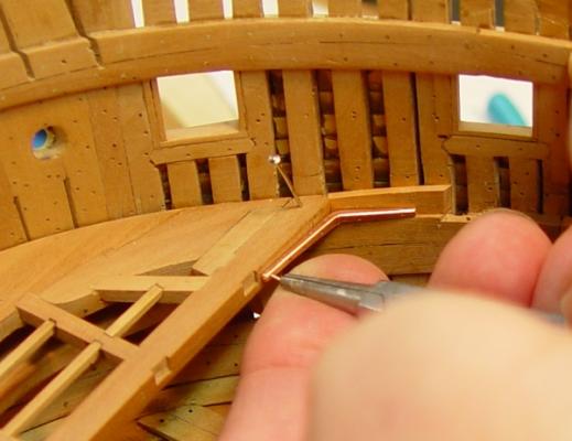
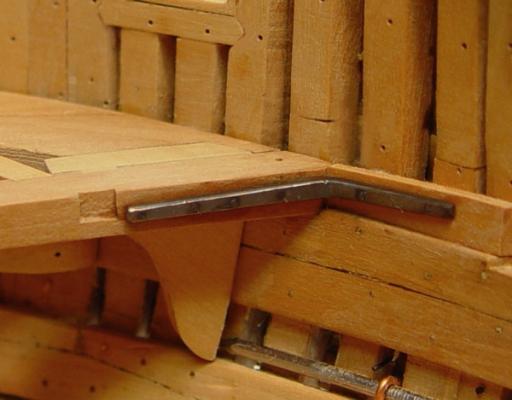
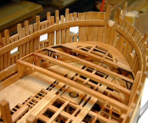
1:60 HMS Naiad 1797 Part 109 Upper Deck Beam #17 Posted 11/17/11 Up to this point the beams from #29 forward to #17 were fitted with angled iron knees to leave the officers some room in their tiny cabins. Beam #17, the first to be clear this area is being modeled with Roberts style plate knees, one on each side of each beam end. The simple chocks used between these plate knees did not require compass timber and that was a key reason to move to iron. The next beam forward, #16, with its beam arms, will be the last to be installed, so after #17 the work will move to the bow area. The Roberts type plate knees were made by photo-etching sheets of .005” copper. The third attempt at etching is shown in the next photo. Photo-etching is, to say the least an interesting and intricate process. I think it will take some practice to get 100% yields, but this third attempt produced 12 out of 14 good knees. In the first attempt the holes came out too big so the size had to be reduced on the “artwork.” The entire photo resist was lost on one side on the second attempt due to poor laminating. I won’t go further into this process except to say there are a lot of steps and some nasty chemicals involved. The next picture shows one of the chocks being pinned and glued to the beam. With the beam in place the chock was held against the side and the pinhole drilled. It was then glued on as shown above. After this gluing step, two copper bolts were CA glued through the beam from the top to hold it together securely. The chocks were then tapered. They are somewhat narrower at the bottom and flush with the beam sides at the top. The next picture shows the plate and all the bolting installed on one end. In practice these plates were set into the wood, but I wasn’t up for that task. The bolts went all the way through both plates and the chock. The model bolts in the plate are really nails. A piece of wire like the one in the picture was forced into a tight hole with pliers, clipped off close to the surface and peened over with a hammer. The extended tabs at the end of the beam will be bent over to bolt into the filling pieces and frames. The black bolts through the chock into the frames are black fishing leader. The next picture shows the whole beam assembly. The next picture shows the assembly fit into place for the marking of the holes in the filling pieces. The filling piece shown is loose and has not yet been cut to size. The next picture shows this connection, after blackening the knees and gluing the beam into place. The bolts in the tabs can now be installed. The filling pieces will be dubbed back to the beam height later before installing the waterway. The next picture shows the beam completely installed, with its pillar (not visible) and carlings. The picture also shows the pump shafts, which need to be detailed and maybe installed before the upper deck framing is done in this area. The four square Cole pump casings have had their clamping brackets installed at this stage – ebony plates with long wire fastenings. The bent wire staples in the top maintain the distance between casings at the top of each pump. The lower deck structure, decking and partitions have been given a coat of finish up to this point. The work will now move to the upper deck beams in the bow area so it can continue in a sequence from smaller to larger sized beams finishing up with the beam just forward of the main mast and its arms. Ed


-
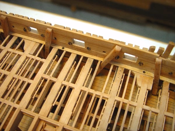
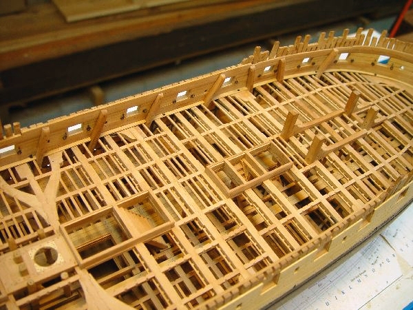
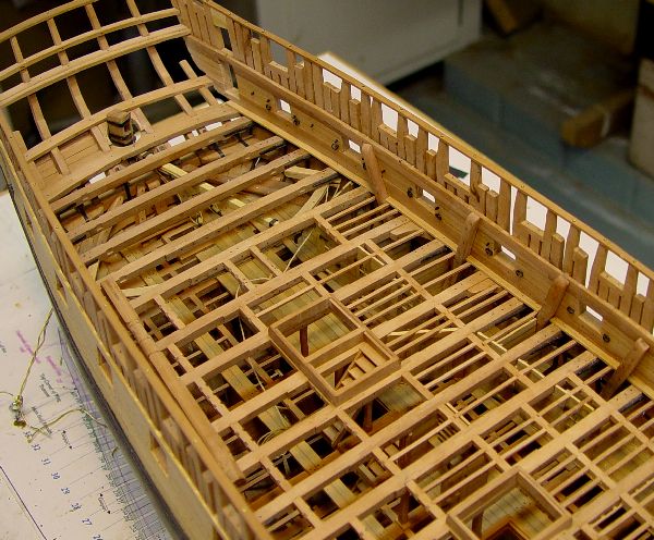
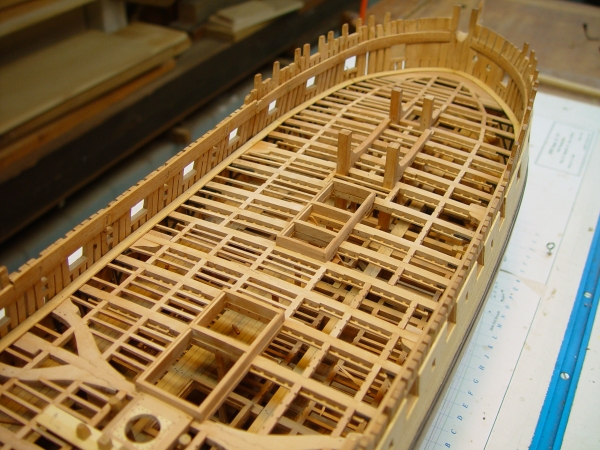
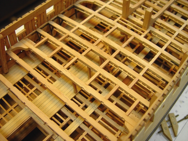
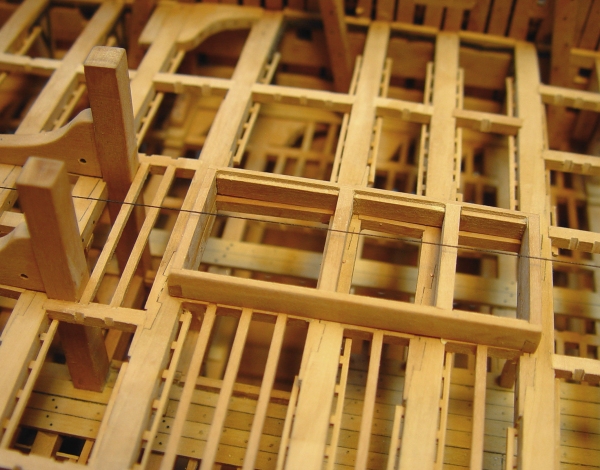
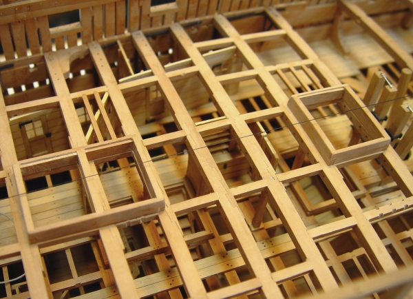
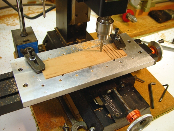
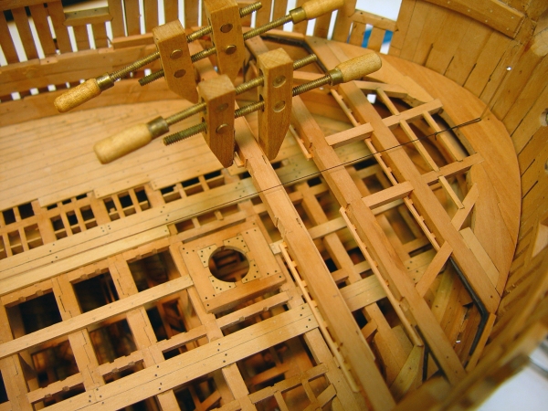
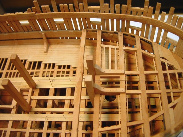
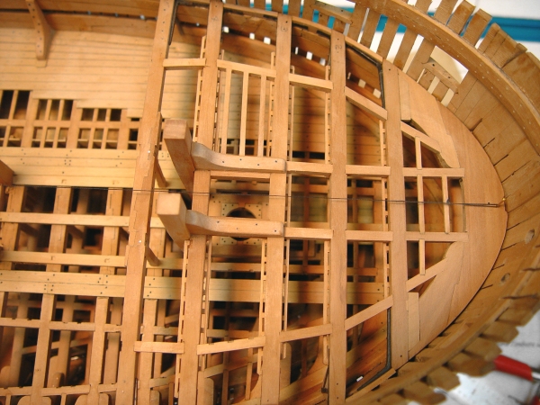
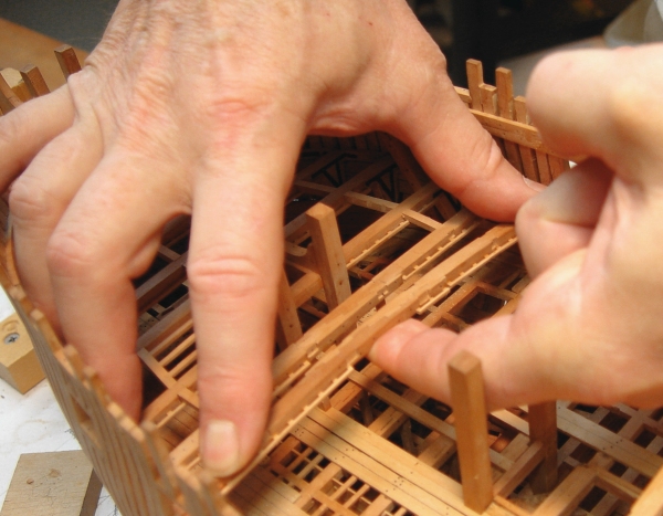
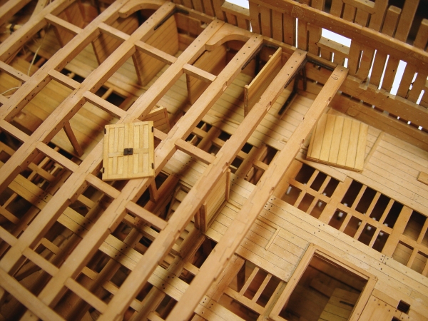
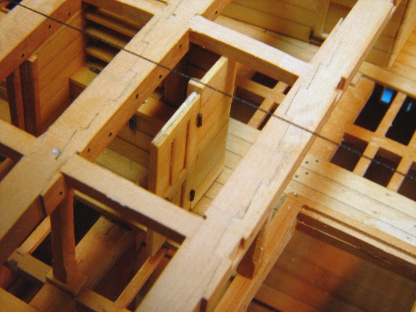
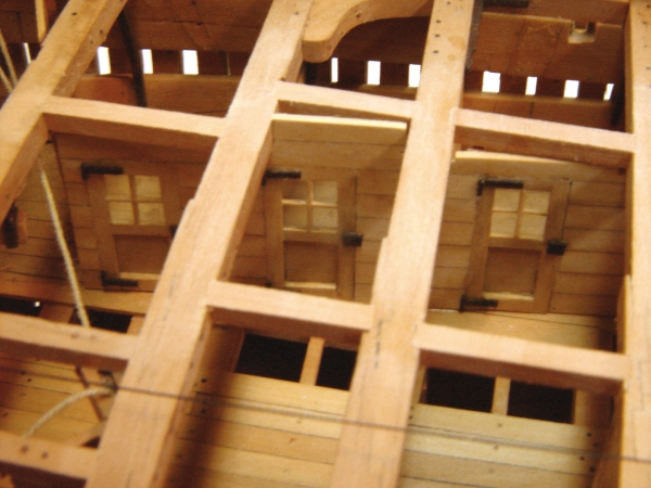
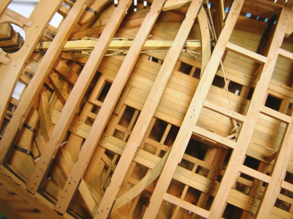
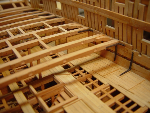
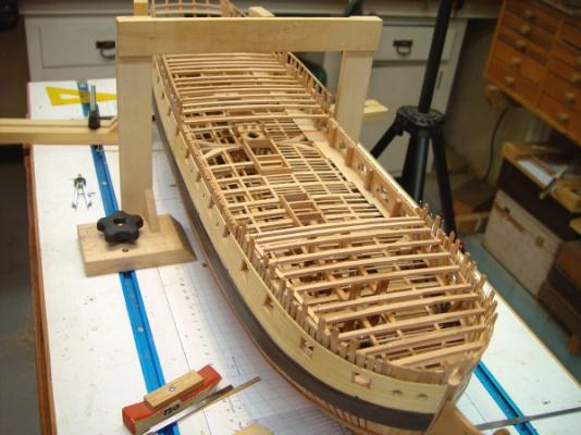
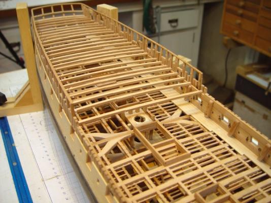
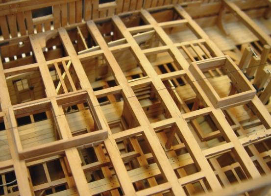
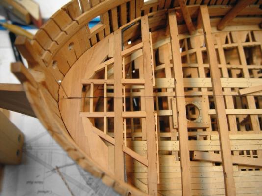
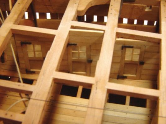
1:60 HMS Naiad 1797 Part 108 Upper Deck Beams, Continued Posted 11/14/11 The upper deck beams continue to march forward – one beam, two filling pieces, four iron knees, 32 bolts, a pillar and four or so carlings at a time – plus some partitions. The first picture shows the first additional beam added since the last part. The next picture shows the ironwork on the other side of this beam. The hanging knee in this picture is canted slightly to get the two lower bolts into the next frame forward of the one holding the standard knee bolts. The boltholes on the lodging knee were drilled to go into a frame. This knee has a short horizontal leg due to the closeness of the next beam forward. There are a lot of partitions on the aft end of this deck and they have been installed progressively with the beams. If these were installed before the beams it would be impossible to drive in the bolts or peen over the bolt heads on the knees. Drilling the holes and installing these bolts is a challenge even without the partitions. Most of the holes into the frames are being drilled with a Dremel tool with a right angle head attachment. The next picture shows some of the partition work in progress. Partitions and doors were prefabricated to fit before the beams were in place, then installed after the beams. This picture shows the pre-made double paneled doors to the ward room and one of the dividers between the officers’ cabins before being installed. The long wall with the officers’ cabin doors is not shown in this picture. It was made early on in one piece but could not be fit until all of the overhead beams were in. The next picture shows that wall installed and also the slanted wall with double doors dividing off the ward room – of if you prefer the officers mess, or my preference, and Patrick O’Brien’s, the gun room. The door hardware in this area was simply made using small ebony bits. This allowed all these very small pieces to be glued with Titebond rather than the messier CA - had blackened copper been used The next picture is from a different angle and shows all the beams and partitions as currently installed. The double, paneled gun room doors can be seen just above the right center of this picture. Just below the center on the centerline is the Captain’s pantry with one paneled door, a storage bin and some shelves. Partitions are only being installed on the port side, which will be partially planked. The starboard side is all about structure. The next picture is a closer view of one half of the Captain’s pantry. The thread running along the centerline is being used to constantly check alignment - more on this below. The next picture is a close up of the three cabin doors within the gun room area. The tiller rope and sheave can be seen to the left. I have not included much on the need for alignment as the decks progress upward. I have shown wire and thread lines in some past photos. This alignment requires constant attention. The centerline is one important reference but the upper framing needs attention as well, as beams are tightly fit within the frames at each level. The next picture shows what I have been doing to keep the frames equidistant from the centerline on both sides. These plywood templates were made from the top part of the frame patterns for every fifth station or so. Since they include a centerline it is easy to check that this line matches the center string line when the patterns are fit over the sides. As internal and external planking gets added the slots on each side need to be opened up so the template will fit. These are being used periodically when the beams or other structural parts are being fit up. The area just completed has involved the most complex installation sequence so far – largely because of the problems getting the bolts in – and some preplanning was well worth it.. With the last of the beams over the officers’ cabins installed, most of the remaining knees will be of a different type. For the most part these will be Roberts plate knees. I am expecting to make these by photo-etching copper sheet. Perhaps some of that will be done by the next part. Ed


-
1:60 HMS Naiad 1797 Part 107 Upper Deck Beams Continued Posted 11/5/11 The work on the beams of the aft part of the upper deck continued. These beams are over the officers’ cabins on both sides so they were fitted with iron angled knees to provide more room in these already cramped spaces. The first picture shows this type of knee fitted right up against one of the partitions – or vice versa. This picture was taken right after installing the bolts in the knee and touching up their heads with some sulfur solution. The picture also shows the ventilation scuttle openings – one to each of these cabins – cut through the deck clamps. The glue residue where the rider was removed still needs to be cleaned off. The next picture shows the other side of this beam. There will be no partitions installed on this side, which will have open framing on all decks. If the partition were installed on this side it would fit right between the iron hanging knee and the standard. Since this side will not be planked on the on the inside, the riders have been left in place. They were removed from the other side so the beams and the interior planking could be fit in. At least one side had to be removed to allow the beams to be inserted. The next picture shows a wooden lodging knee being fitted to the beam in the above pictures. There were some wood knees installed along with the iron, but I do not know why or the logic for where they were installed. The next picture shows the rudder rope sheaves with their brackets installed beneath the beams and carlings just forward of the mizzenmast. The purpose of the spool is to try and keep the excess length of rope out of the way until it can be rigged up. The next picture shows an iron hanging knee fitted to a beam. The knees are first made and positioned on the beam while it is in place so at least one bolt hole can be marked. It is then bolted to the beam with copper wire through bolts. The knees and bolts are then cleaned with acetone and treated with sulfur solution before installing using a cotton swab. I had been doing this treatment after installation, but found it easier to do it at this stage and then touch up the side bolts after. The plastic cup at the top contains a complete batch of sulfur solution. It works best when it is fresh and the amount in the cup is many times what is needed for one beam’s ironwork. It is applied with a cotton swab. The surrounding wood seems to return to its normal state whether the solution is washed off or left on. The solution neutralizes to a clear liquid. All these beams forward of the tiller are supported in the center by pillars. The next picture shows the height of a pillar being measured. The pillars are being mortised into the underside of the beams and in this case into the top of the head ledge of the hatch on the lower deck. The other pillar in the picture is let down into a mortise in the thicker central deck plank. The next picture is an overhead view of the aft beams and the tiller sweep installation. the carlings for the aftermost five beams have not been fitted. They will support half beams midway between the main beams. I still have a bit of research to do on these. Prior to taking this picture, the lower deck and the structure below the upper deck in this area was given a coat of finish while it is still accessible, since no further work will be done on this. The last two pictures show some of the progress on the beams forward of this area. Both these pictures give a pretty good idea of the amount of ironwork in this part of the ship. This side will be fully planked on the inside. This side will not be planked. Carlings are being installed progressively with the beams. Ledges will be installed later. Once the beams proceed to the end of the cabins the ends will be supported by Roberts plate knees. That will involve a new and interesting modeling process for me. Ed
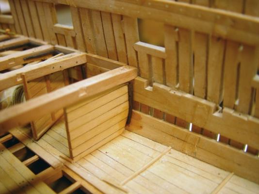
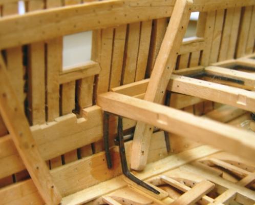


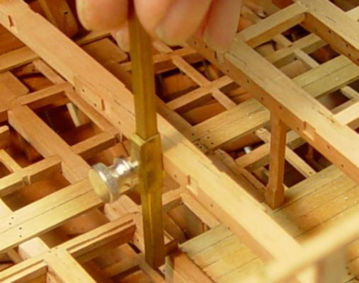
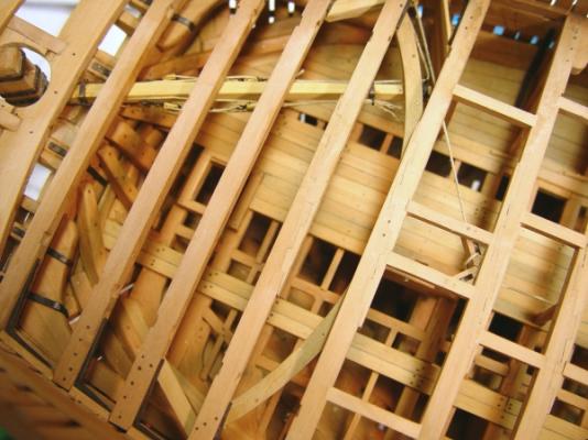
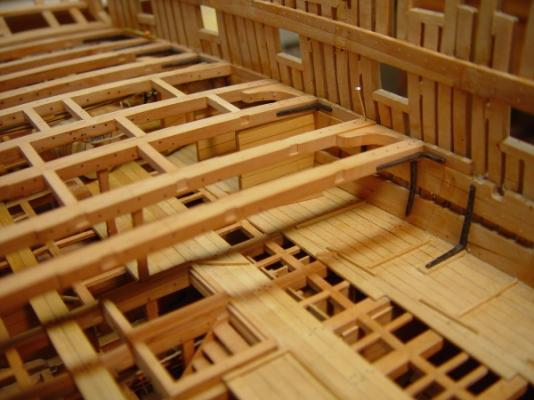
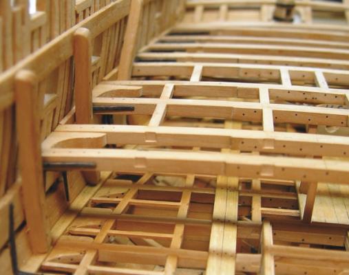
-
Guy,the partitions shown above are on the lower deck, so I assume you are asking if they are like those on the platforms below. I used the same process for all the partitions but the doors get less plain at the higher decks. I genrally described the process in part 106, so I'm not sure what I can add to that, except to answer any specific questions. For the wall panels, check out part 47. The window mullions in the doors are made like small crosses slit from a wider strip that was notched on the mill, or the saw, I can't remember. Either way works with the right size blade. The crosses are then cut to fit into the window opening. Does this address your question? Ed