


ChadB
-
Posts
184 -
Joined
-
Last visited
Content Type
Profiles
Forums
Gallery
Events
Posts posted by ChadB
-
-
-
-
-
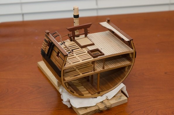
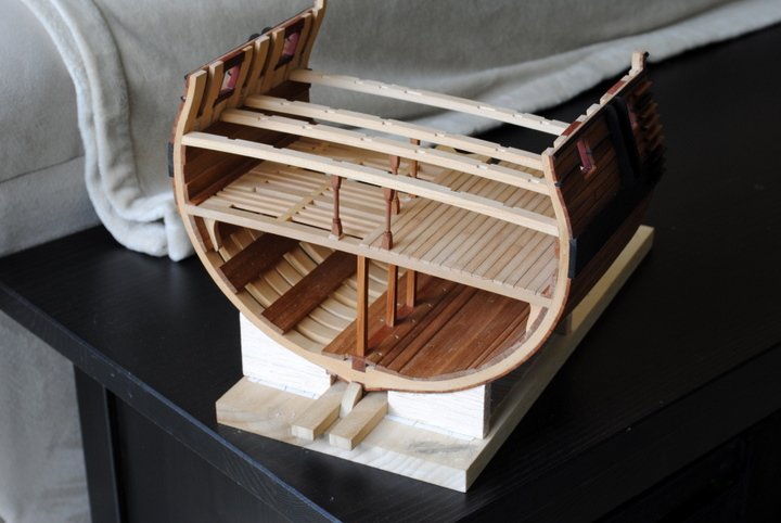
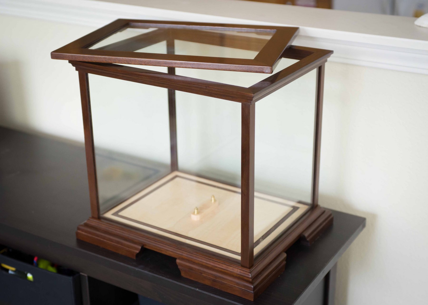
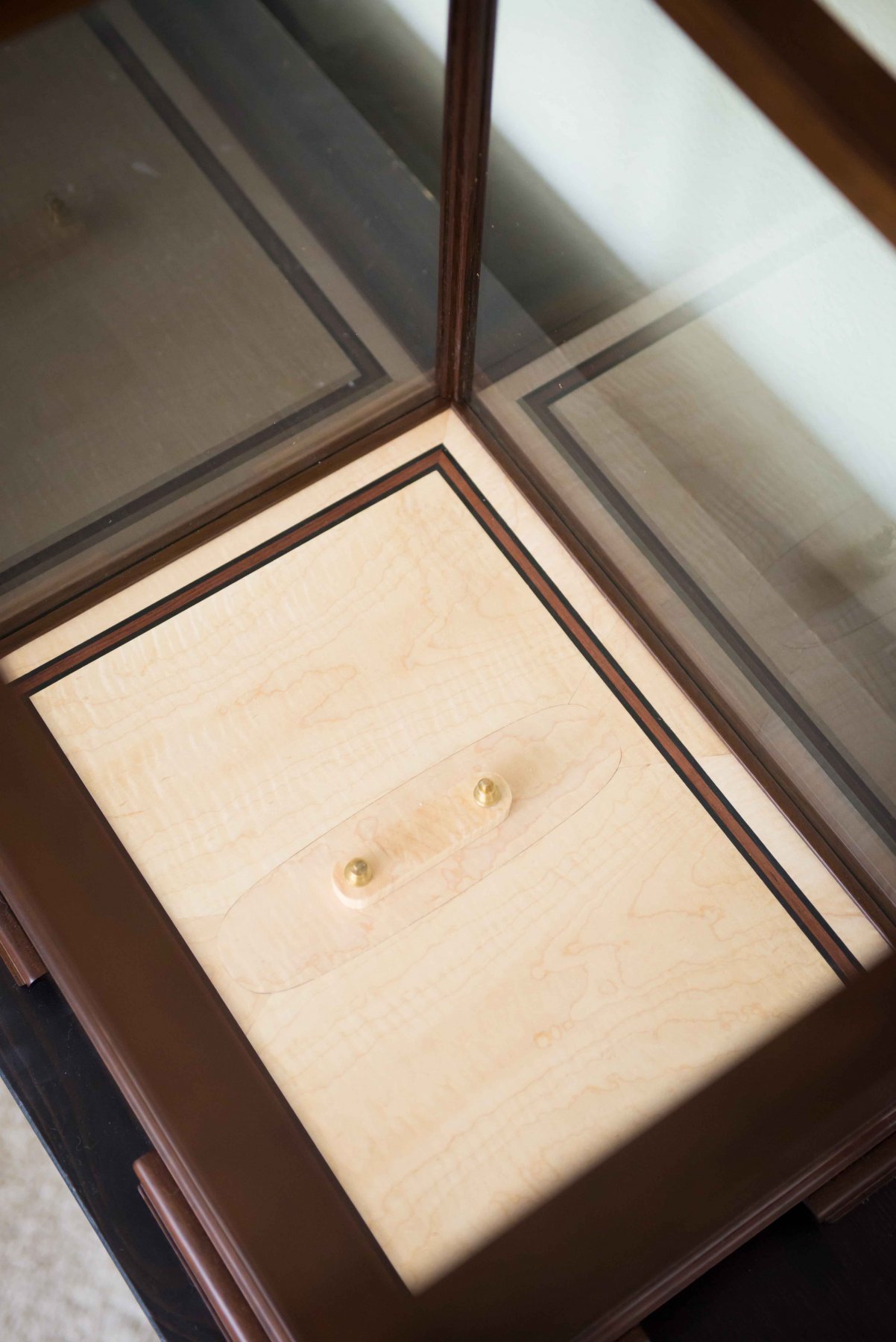
...and with that it was done. I then ventured into my first somewhat -bigger woodworking foray and making a case. I was surprised (and have continually been) at how robust the Byrnes table saw is at cutting bigger stock. I made the case out of Peruvian Walnut which is a fairly soft for a hardwood (and very porous) and finished it with a french polish which is a total pain in the *** but looks beautiful. The base is curly maple with an ebony and rosewood inlay, and the model was mounted on two turned brass pedestals. As i just mentioned in my comment to Derek I really wish I had the forethought like him to install mounting hardware way back in the beginning, the problem being that my cross section kept listing because of the cannons on one side. It ended up taking epoxy to get it to sit right and now the Triton will never be leaving it's stand!


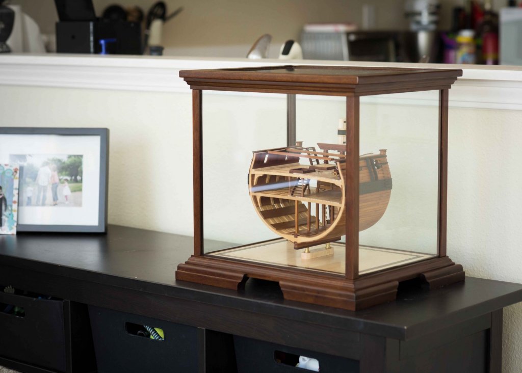
And that's that! It was a fun (and glacially slow) build, but I couldn't be happier with the final product. Every day for the last couple years my wife and kids walk by my Triton cross section, stop, stare in awe, and never fail to exclaim something like "Wow, Dad- that is amazing!" Just kidding- none of them care and the only time they mention it is when we need to move it to put up the Christmas Tree.... but to me it was the journey. Everyone is going to have their own outlook on modeling, but I hope if you are starting this project that you don't take the mindset of this being a throwaway project that leads to something bigger- enjoy the ride and do the best you can. Personally, when I'm old and my hands don't work anymore I'd like to look back on this hobby and have built maybe a handful of incredible models that I know I put all my effort into and will be kept in the family than a houseful of models that I blew through and my kids toss in the trash the day after I die. Enjoy the ride and make sawdust! -Chad
- mtaylor, VTHokiEE, Jolley Roger and 8 others
-
 11
11
-
35 minutes ago, Derek C said:
I am building this now , thanks for the posts your log has been very helpful and your cross section is beautiful
Derek
No problem Derek- Your cross section is coming along great! I really like your forethought into mounting hardware- it will really pay off down the road (mine was an absolute pain to mount without it lopping over to one side).
-Chad
-
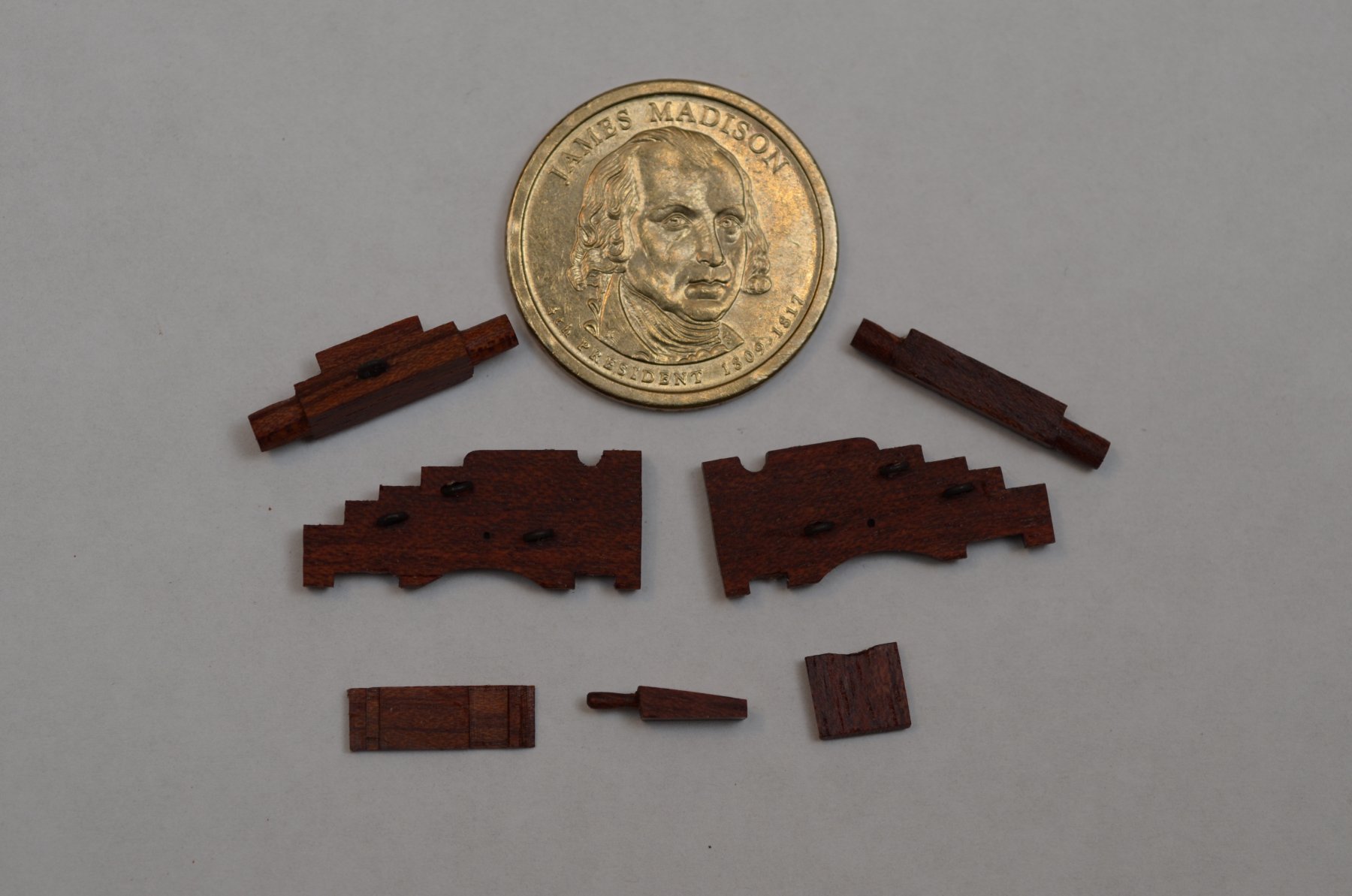
Carriages
Carriages were cut from bloodwood and wheels turned from boxwood I believe. It was pretty straightforward using the plans, although you can see where I needed to wrap the front axles with black construction paper because I sanded it down too much. This actually helped keep them from rolling around. Once they were assembled the blackened cannons were mounted.
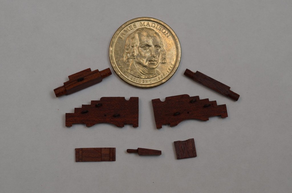
After that they were installed on the model and rigged!
.jpg.4245e0cae514d2ebd5c41f58928cff21.jpg)
-Chad
- Gabek, Captain Poison, mtaylor and 1 other
-
4
-
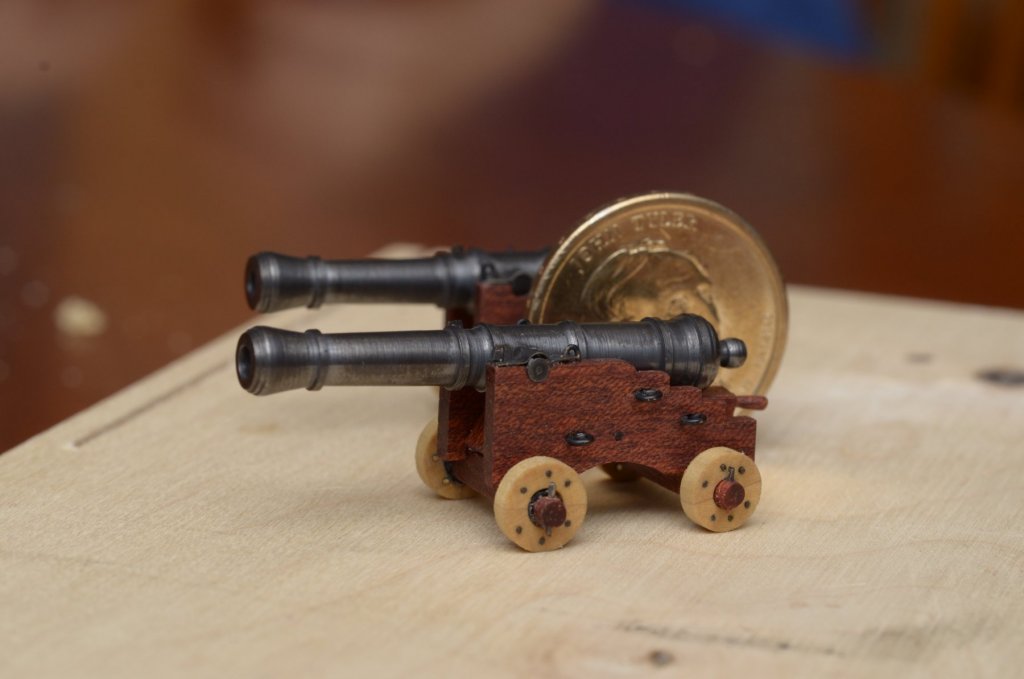
Cannons
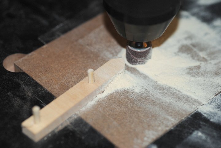
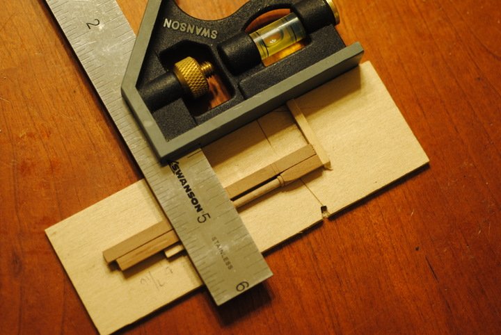
Turning the cannons started with a drawing that was way more intricate than it probably needed to be (but resulted in a nice finished product). My guess is I was stalling as long as possible before I HAD to use the lather and actually turn them.
.jpg.0a3bc9e75031bd6b597697141b977731.jpg)
I came up with this wacky setup to measure distances on the lathe, and although it worked I think I'll find a better way of doing it when the day comes to turn cannons again.
.jpg.fb0df13041fd3f8d3a5eb5214a99e187.jpg)
Then it was just a matter of turning them. The first couple were scrapped but then it became a pretty easy process once you got it down. It was nice only having to have two really good ones.
.jpg.206e0f853a7eec5211a0007275423f96.jpg)
.jpg.c64f554c0aee2ecd4b68ade58b237dbc.jpg)
.jpg.05e7016ee66332c99a08542efa473bfd.jpg)
.jpg.b02d7a310a106618f3efbfb06235733e.jpg)
Drilling out the trunnions was done with a simple little jig, although getting the offset requires them to be pretty snug so they don't try to turn.
.jpg.a14dc0f5c6be3c41dc81c4eeaad18146.jpg)
-Chad
-
Well... unfortunately, that's where the saved file of my original log ends so the rest of this may be incredibly anticlimactic (and if you jumped in somewhere in the middle and are incredibly confused on what the hell is going on, the first post should explain it all). When I did the original build log I included as much detail as possible so that others may have something to follow as something of a practicum, so if you've made it this far then the rest should be a breeze, anyway.So without further adieu, here's some photos of the ladders and cannons with me trying to guess how I did it five years ago!
Ladders
Ladders were made out of Indian laurel using somewhat of the same process as the louvres for the well mod. I made this little jig to keep everything squared and sturdy while inserting the rungs since it was pretty delicate. I had dry fitted the sides first, knowing that trying to cut out notches or sand them after the rungs were inserted would be a disaster.
.jpg.1584a345bfd3b6b7d94138e3cca2dd4f.jpg)
.thumb.jpg.d48a30df0044e5b248bf614d9722e7ba.jpg)
.jpg.0c5f937913faab15bfd11e64c0d2bf06.jpg)
-
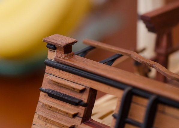
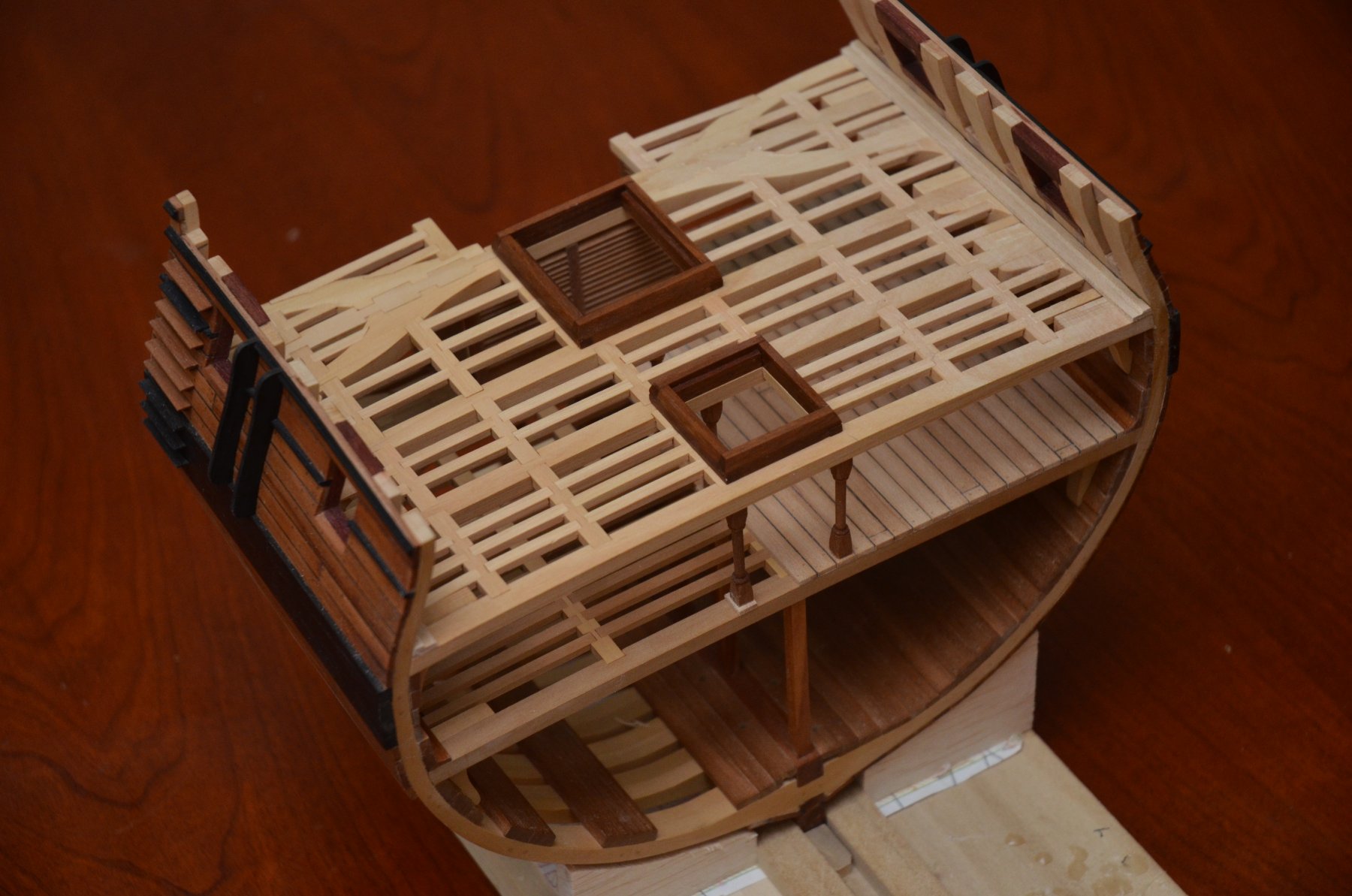
Railings, Catwalks,
Well, it's been a while (again), but some work has taken place and hopefully I can put this baby to bed over the next month or so. It's funny how, as a parent, you think you'll get more free time as your kids get older, but it generally seems to be the opposite that happens. Oh well-they're only young once and soon enough they'll be rolling their eyes at me!
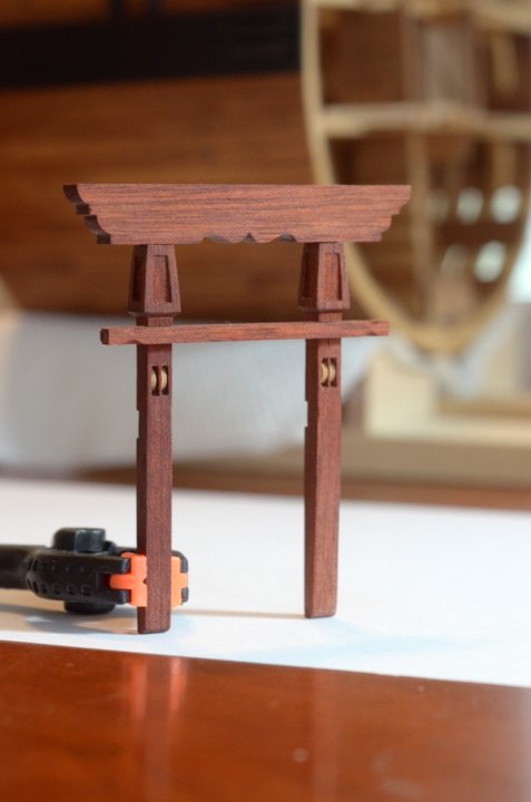
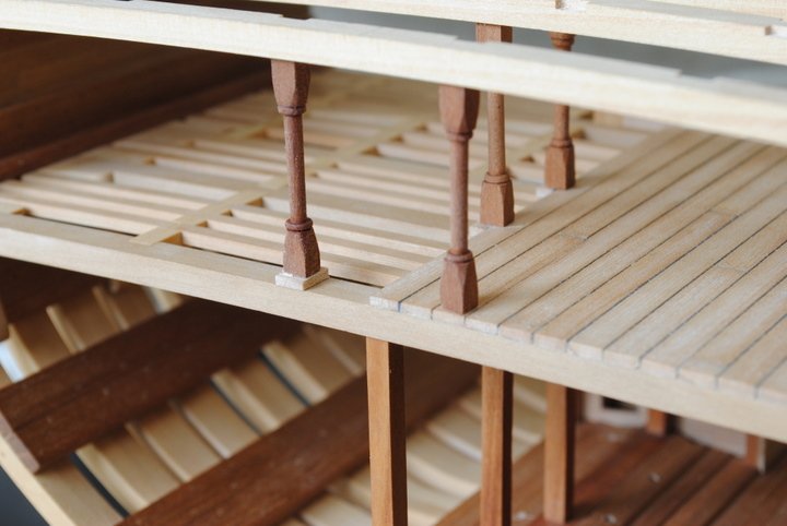
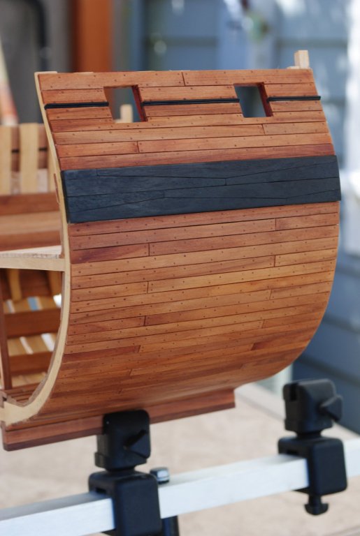
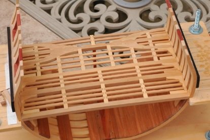
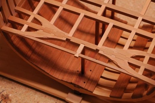
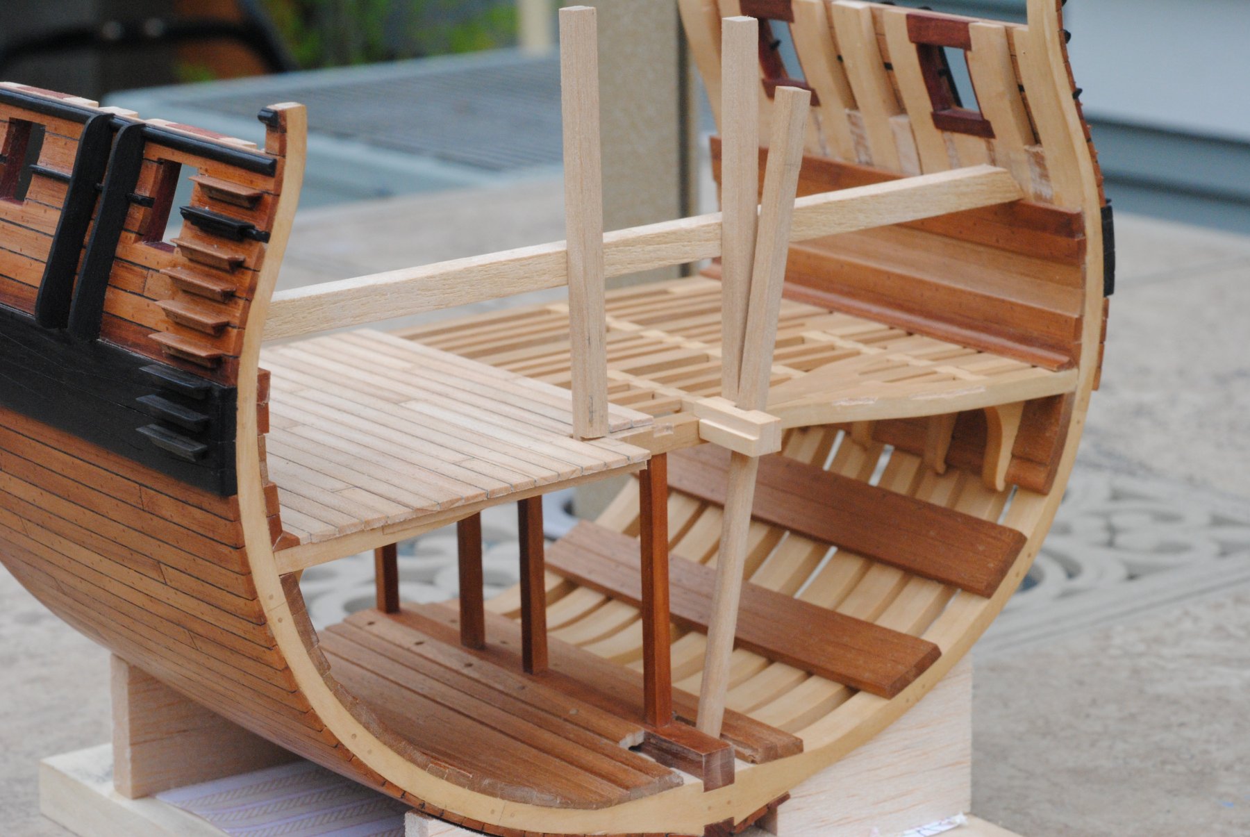
So the first thing I took care of was the railings. I've had them made for quite some time, but was hesitant to install them until I figured out how to cover the exposed section on the rearmost frame. It's been bugging me for quite some time and finally stumbled upon one of the Triton drawings that gave me a clue. I took a little artistic license and came up with this (this and rails were made of Indian laurel)...
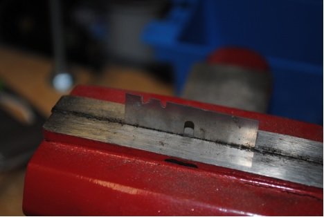
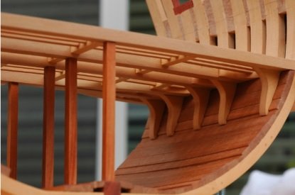
Once that was done, it was time to start on the brackets. The two problems I encountered while making these were cutting thicker brass sheets, blackening them. I used something a bit thicker to add a bit of structural integrity, but didn't feel like sitting there scoring a strip for a half hour (cutting made it curl and bend toward the cutting side). The solution was scoring the strip on the edge of the sheet to the right width a few times with an exacto and a ruler, then bending it off with a pair of cheap welding pliers from harbor freight. Now, they're cheap for a reason- I needed to file the edges so I didn't mar the brass, but after that worked well. I think at some point I'll cut up some thin rubber strips and glue them into the jaws. Finally I just gave a quick file to cut side of the brass strip and that was that. I decided to solder the brackets, which was a pain without a set of helping hands- so i'd suggest one of those little bases with the alligator clips on them to avoid frustration with this. The second problem was blackening. This thread pretty much sums up my ineptitude without going into it here. The short story is I stink at getting Blacken-It to work and ended up painting them. I wanted to stay away from paint, but the finish with the powder black model RR paint I used looks fantastic. I ended up painting over the bands on the mast also because it looked so good.
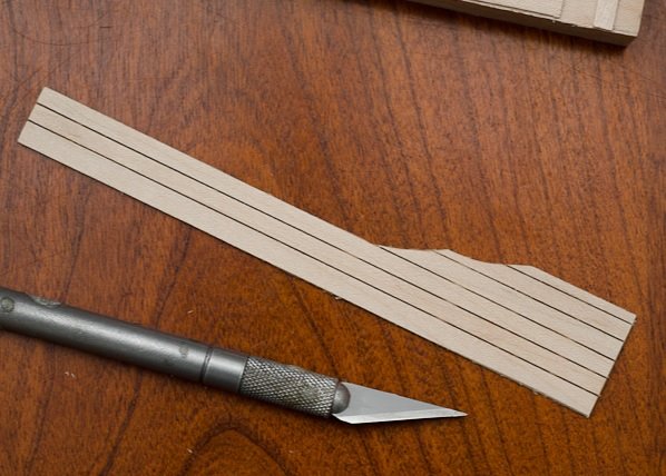
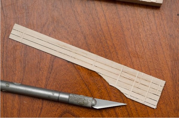
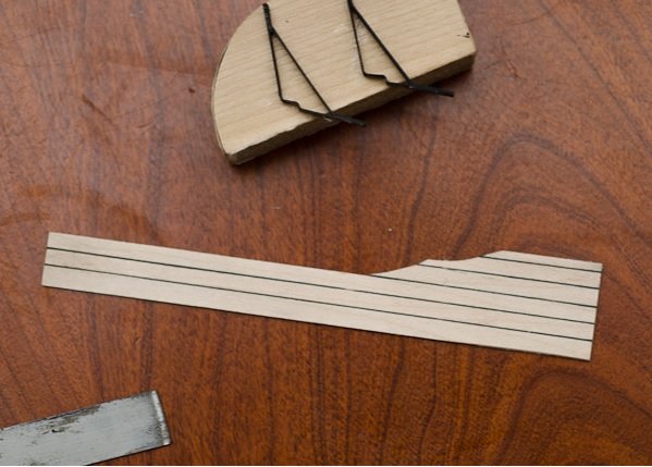
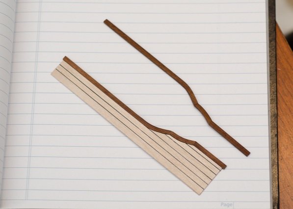
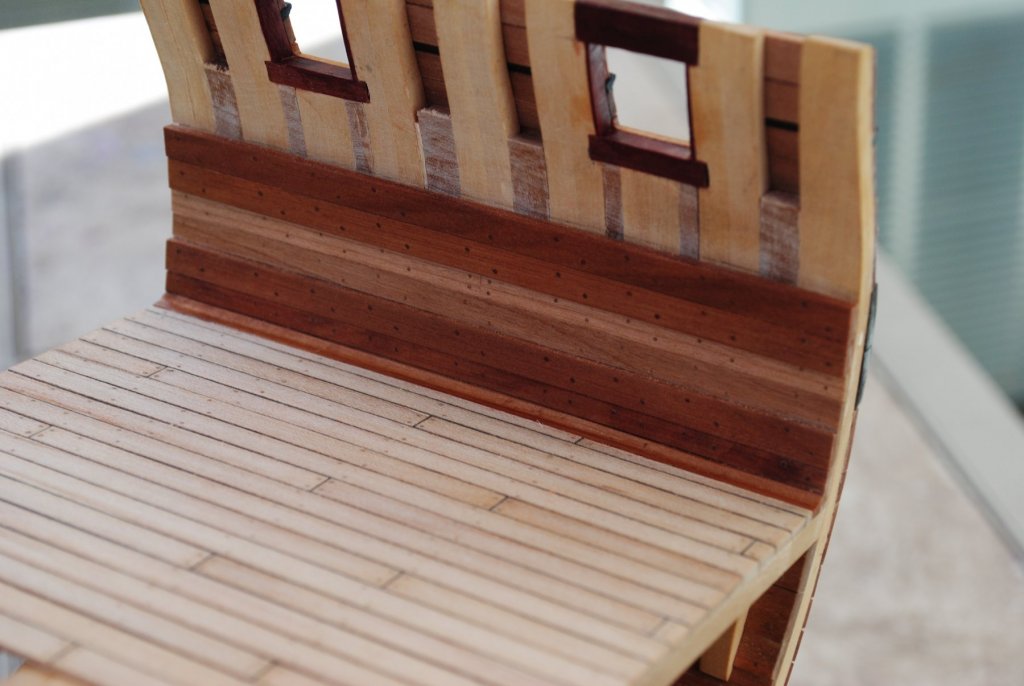
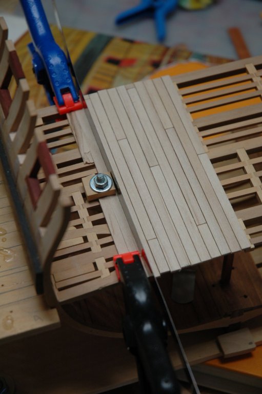
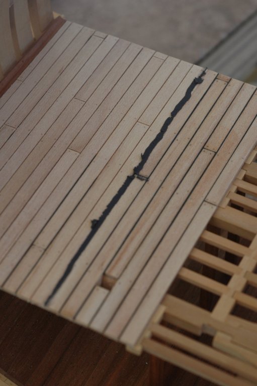
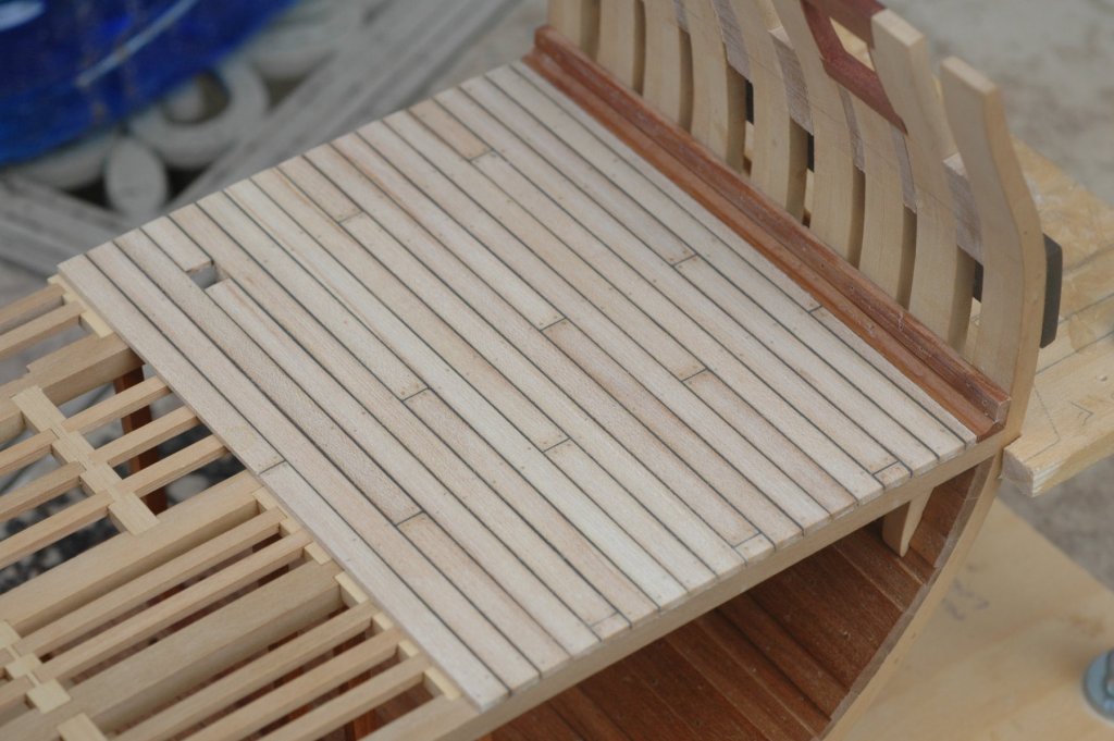
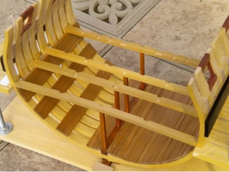
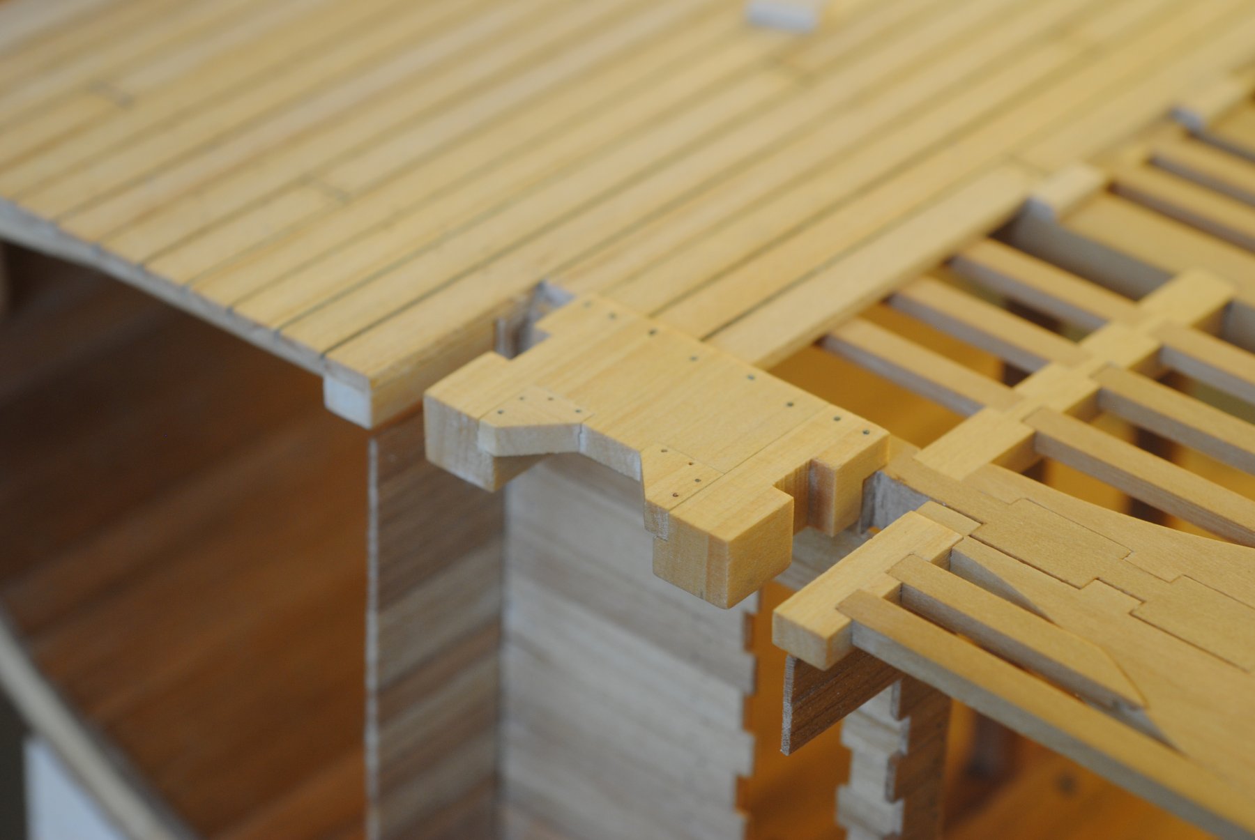
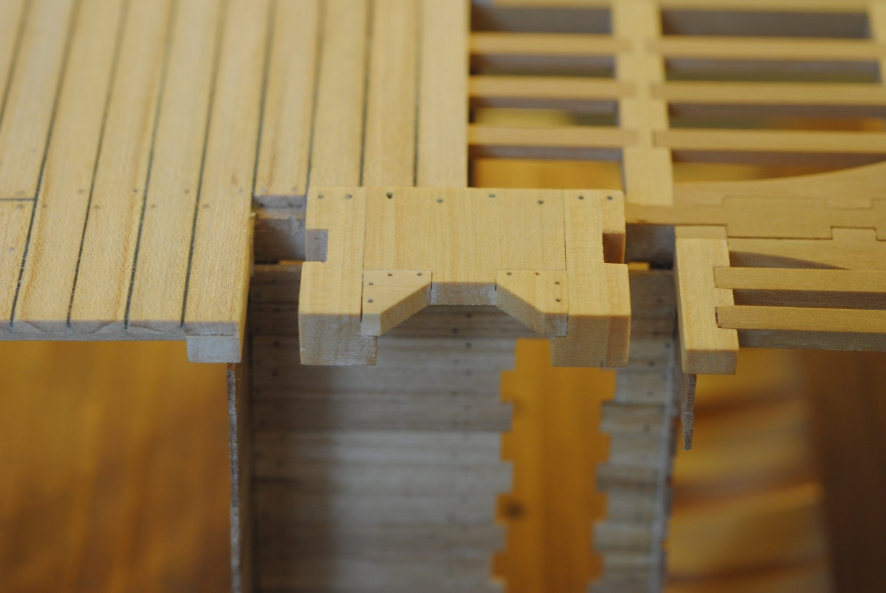
Next were the catwalks. i wanted to make them off the model so I could caulk them the same way as the deck. If I did it by laying the planking on the brackets, I was pretty sure I would ham-fist it and break something. The challenge is finding a way to make a gap between planks from end to end but still have it all connected without seeing. The answer ended up being using a slitting blade to add a very small batten to the back. I started with the three long planks and added the battens where the the brackets would be It would be tough to see anyway, but just in case...). Unfortunately I sometimes lack foresight and forgot about the rest of the planks to follow, which is why in the second photo you can see all the other battens. Once the three long planks were battened, I made the next plank and slit them, then added the batten, then rinse-and-repeat fro the next two planks. When it was all done it was waxed, then caulked the same way as the decks (done in maple).
battened, pre-caulking..
back side showing battens...
caulked..
I actually made the edging (Indian laurel) first, so that was probably a bit "cart-before-the-horse," but pretty straight forward. They're made of three pieces then glued together. It's worth noting that I probably gave myself the second "best' cut with an exacto blade (brand new, even!) during this step. I'm glad my wife is a nurse and was able to get me to stop hopping around like a little girl, but was quickly followed by a stern look and a declaration of my future demise from my tools. Moral of the story-be careful.
To install them, I wrestled with what to do with the "open" side of the model-I didn't want a full catwalk, but I also wanted to make it's presence known. I settled on only the edging, which i really like the look of. I'm still not sure if I'll do guns on that side, but if I do it will give a full view of them.
Other than that-the mast has been secured, so the "well-mod" is officially completed, and added the ringbolts for the gun tackle. So really it's only ladders and guns now...let's see if i can get in under 5 years

- Jolley Roger, Derek C, mtaylor and 2 others
-
5
-
Grating
Alright then, so back to work-where did I leave off? Seriously-where did I leave off, because it was six months ago... HAVE been working the last couple months as it's been getting bearable in the garage. I decided with the planking for the gundeck that I was going to start ripping my own planking, which turned out to be a bit more work than I anticipated. The first set I ripped and lay down all the way to the waterway, when I realized it was thinner than the lower deck planking. For whatever reason this bothered the bejeezus out of me so I tore it up and started again. Since I had it tore up, I figured I might as well punish myself and lay down the top and butt planking under the guns, also. I went ahead and ordered the Jim Byrnes jig for making angled cuts, which worked pretty good, although I think some improvements could be made to it. I did the decks the same way as the lower deck (an upside to making a really detailed log is if it takes you four years to make a cross section, you can go back and teach yourself how you did the lower deck!) and was pretty happy with the results.
. Aghh..just a little humor there after awaking from my winter hibernation. Actually I
The planking around the ports was done in bloodwood to match the insides of the ports and was pretty straightforward. I trennailed it with bloodwood, which was a pain in the butt. A good tip for pulling hardwood through a drawplate is to give it a light sanding with 300 grit sandpaper between holes. Until I did that the dowels would snap on me every time. I also drilled the holes for trennails and cannon mounting hardware before installing since the angle of the deck would make it tough to get in there afterward.
The grate was done according to the procedure set forth by Bernard Frolich in The Art of Ship Modelling. I haven't poked around MSD to see if the procedure is in there, but if not I could put together a tutorial for anyone that would like it. This was my first time making grating and had a pile of scrap boxwood at the end, but was happy with the outcome.
.jpg.f949dc6188fffa9fbe8cd2fec129c6a5.jpg)
.jpg.c8c9fbf21b7996e9622f6d08ad33d767.jpg)
-
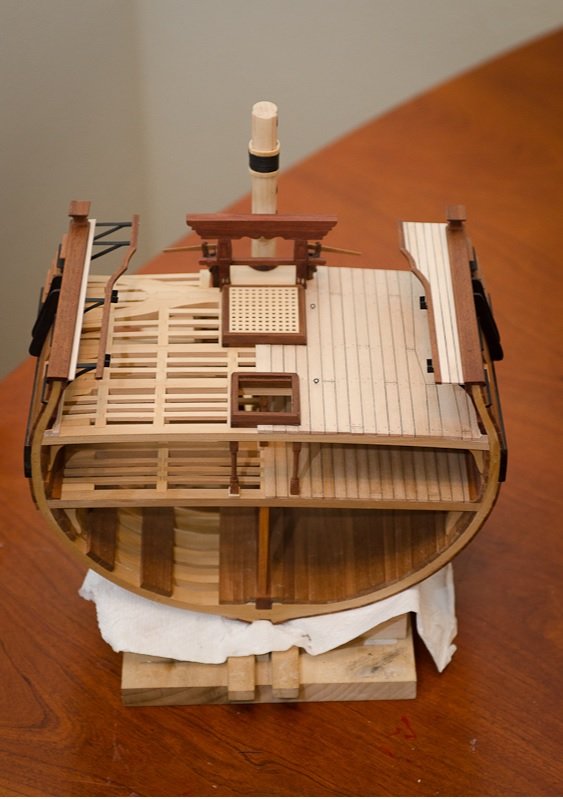
Bitts, Mast, and Pump Installation
Alright-the "well, mast, and pump mod" is essentially complete.It turned out take more time researching and planning than to actually make everything, but I'm pretty happy with the results. The mast and pumps will be set aside until the deck is planked and the chance for destroying anything has been minimized, but they all fit nicely together. The bitts have been installed and hopefully will stay in one piece while my fat fingers work around them. Here's a photo of them installed (and dusty...)
.jpg.f342fba55aaf31ed4a5fb09f6d5c4bc3.jpg)
The mast was turned from hard maple and the front fish and fillings were made from the same and finished with wipe-on poly. The woolding hoops were made from boxwood and finished the same way. I tried to make them out of cherry for a bit more color contrast, but boxwood turned out to be the only wood I had on hand that would allow me to sand the rings down that thin and not break in my hand The bands are all blackened metal and covered with a clear enamel and the woolding is line that has been rubbed with flat black paint. The pumps are made of indian laurel and finished with tung oil, and the plans for them came from TFFM. The handles are made of apple for a bit of color difference, which apparently didn't happen since they look identical. The metal band around the top is blackened metal and were an absolute pain in the butt to attach. I'm just hoping they'll stay on...
.thumb.jpg.6c2758db8b8ac3e68aac0c62fe113ef8.jpg)
It's tough to see in the above photo, but there's a small dowel between the wedges on the mast that will keep it in place. I may do the same thing to the pumps, but haven't decided yet. The gun deck planking should keep the port-side one in place, but I'll need something if I don't plank around the "open sided" one. Anyway-here's the "finished" product...
.thumb.jpg.df87f7b0d5bd8a466a942a406f8a2b1a.jpg)
-2.jpg.d2e5ae8d45c4e0059ba52aff5d40aefb.jpg)
-2.thumb.jpg.fbc2622ac712e81e8e0b8c9a90b4ed32.jpg)
.thumb.jpg.3c1e2e5694d21870c2789f6131723f29.jpg)
-
Bitts
Anyway-Things are moving along and most of the mods are done, or at leastto the point where it all fits together nicely. Until I get some photos taken of the pumps and mast, here's the finished sheet bitts. I decided to fancy them up a bit since it was one of those things on the cross section I really liked the look of. The structure is made of bloodwood and the sheaves were turned from boxwood. The only real hitch was getting the slots for the sheaves to have a rectangular shape since it's such a small space. The best way I found to do it was once it was drilled out to the approximate width (which leaves the top and bottom rounded a bit) to put two scroll saw bladed through and manually saw the top out to square it off. Then take them out, turn the teeth the other direction and do the same thing. I probably could have spent a bit more time on it, but was getting a bit antsy to move on to the pumps.
I'll also mention that the overall design was shamelessly lifter from TFFM vol.1. I've said it about a thousand times since I've gotten them, but they've been an incredible help so far. I'd highly suggest them to anyone, especially if you are thinking of undertaking this cross section.
-
Upper Deck Planking, Coamings
The deck is done the same way I did the lower deck, with boxwood and a wipe-on poly finish. The hatch coamings are done in Indian Laurel, which wins the award for worst wood I have ever worked with. It's like cutting a rock on the table saw and smells like butt. -Chad

-
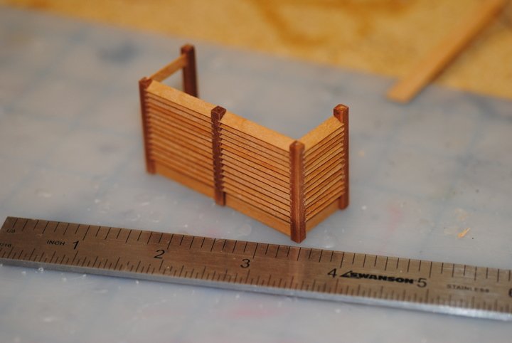
Well Mod Pt 2
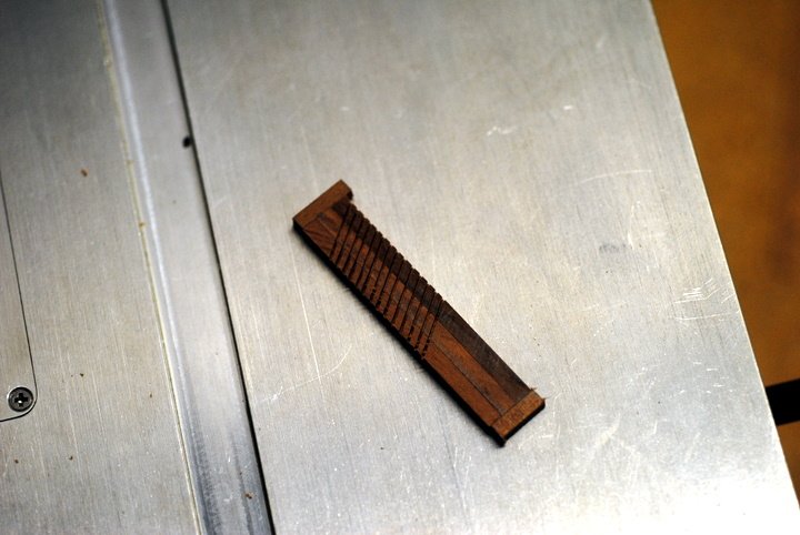
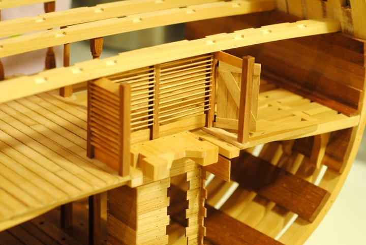
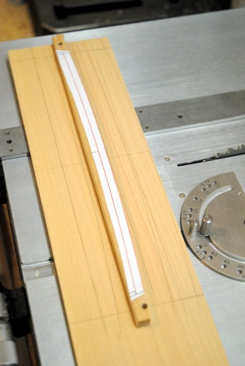
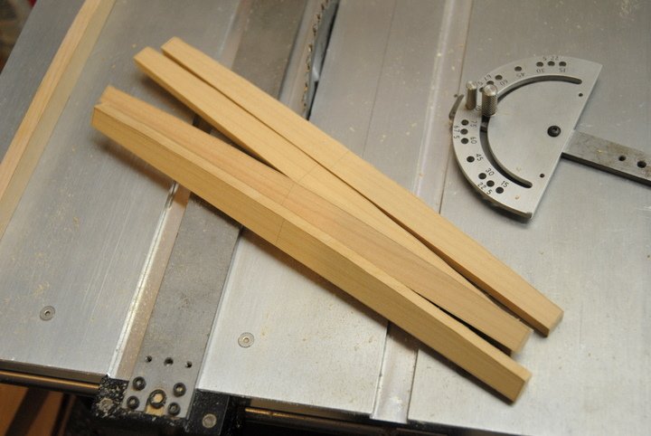
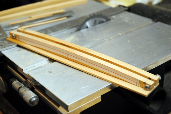
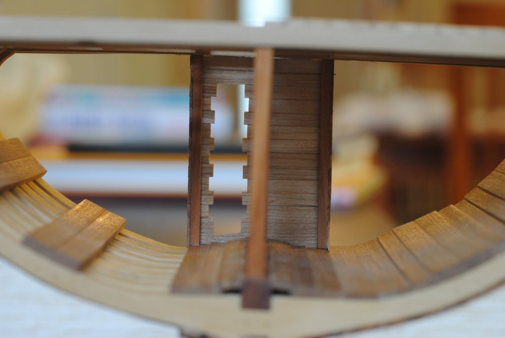
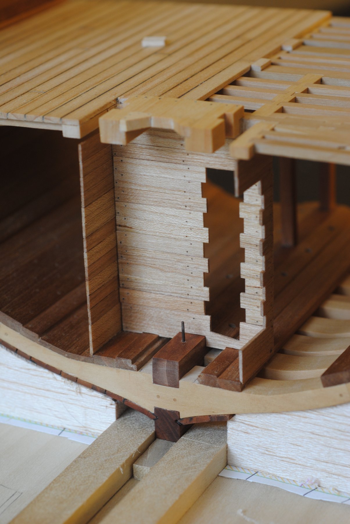
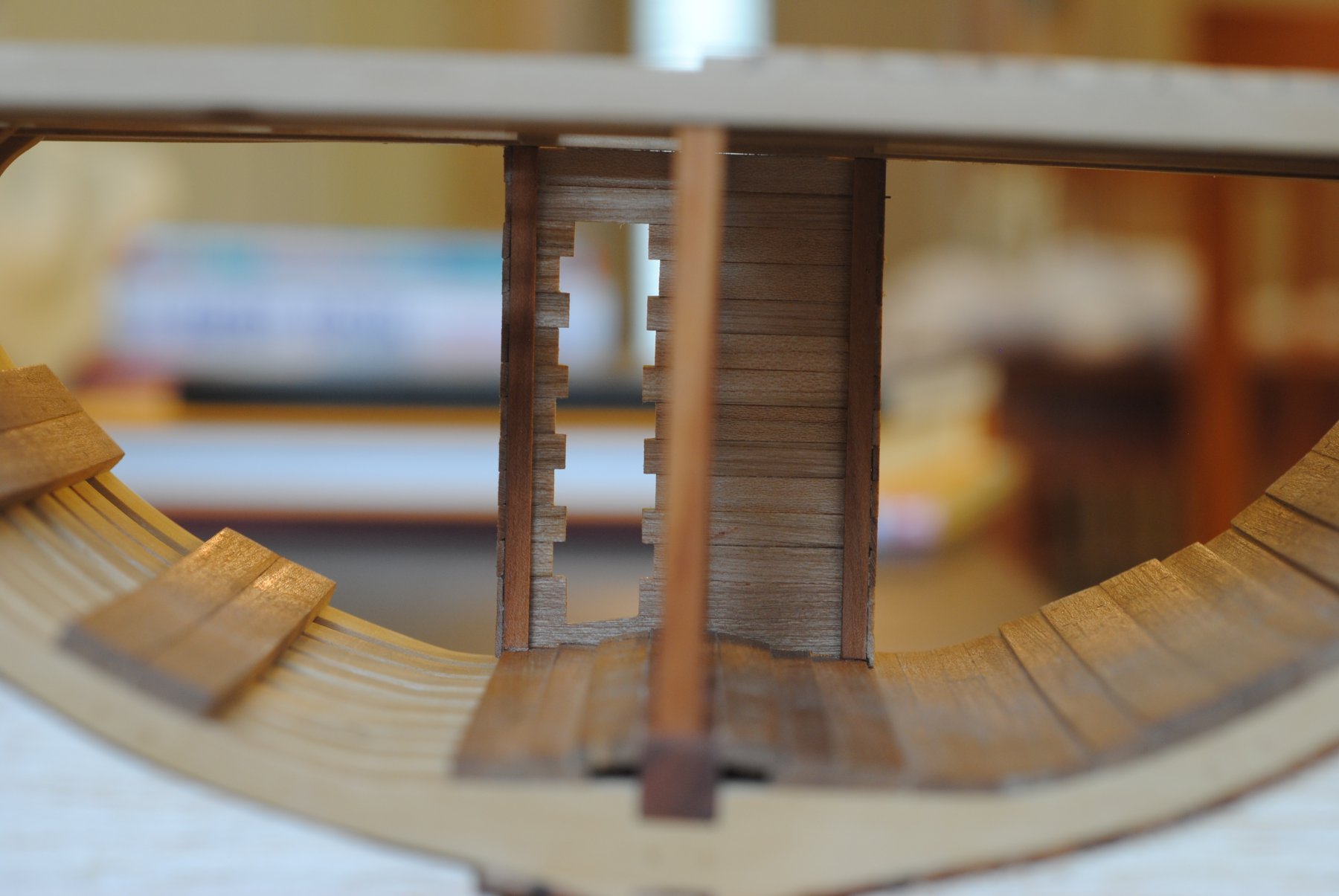
OK, so I finished the upper well and Greg was right-fitting louvers was definitely not a breeze. That being said, it wasn't TOO incredibly hard-just took a lot of thinking thru and the problems I did run into were all self-inflicted. My two main sources for this were TFFM (again..) and Gary's Alfred build (again...). The upper well consists of essentially a room that is fitted with louvers on all sides (ventilation?), stanchions on the corners, and a door for access. The first and hardest step was making the stanchions, which included the slits that the louvers would sit in. If all the slits didn't match up, then the louvers would be crooked and probably look bad-so that was the first fear to conquer. This was overcome by cutting all the slits at one time into stock that was cut purposely long. The stock was all put together with the ends glued to scrap to keep it together thru the process..
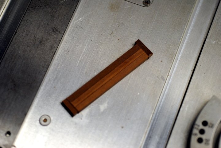
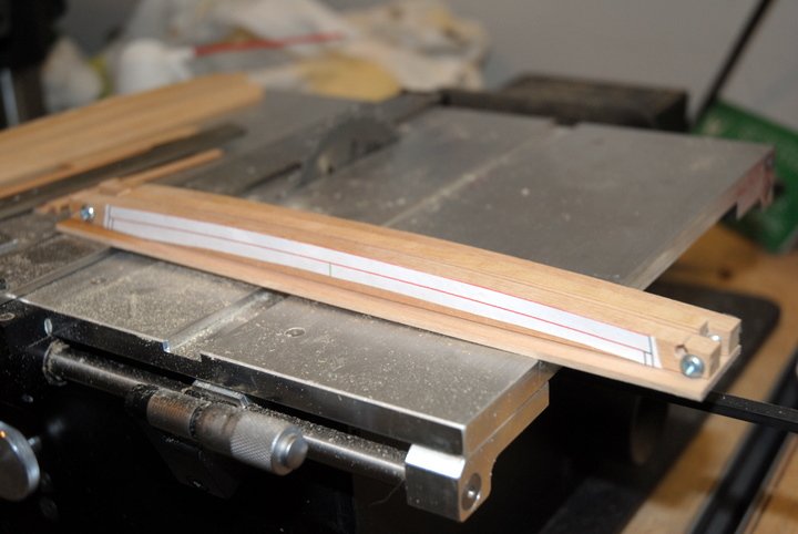
I then set up the tablesaw, which is just setting the angle and using some scrap as an extension. The fence was used to keep the scrap extension from sliding around...
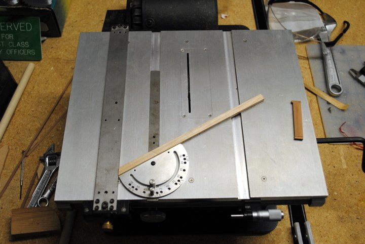
Now the slit cutting can be done essentially the same way as most how-to's on making grating, but for some reason that totally slipped my mind until I was all done (this seems to happen a lot to me..). I just lined up the stock for the first cut (with the blade set to about 1mm height), then moved the stock fort he next cut by lining up the previous cut to a mark on the tablesaw. Essentially I eyeballed it. I got lucky, but I don't think I'd try my luck multiple times...
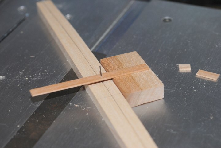
After the first cuts, it was necessary to turn the stock pieces to the proper alignment for the next cuts if needed. I'm not the sharpest tool in the toolbox, so a good diagram came in handy for this step. Matter of fact, one of the best things I've started doing is keeping a notebook with notes on stuff I come across or ideas...
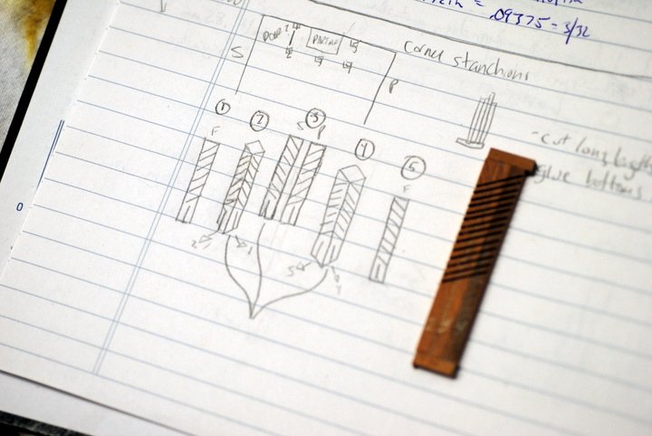
Once I decided what direction everything needed to go and that the cuts would be correct (I honestly sat there for about 20 mins trying to figure this out..) things were aligned and put together the same way..
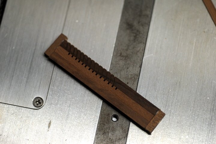
That finished all the cuts. The effort put into making things were aligned payed off when the louvers all fit nicely. Fitting them was fairly easy, although the thickness took some playing around with. Too thick and they won't fit, too thin and the whole thing loses any semblance of sturdiness..
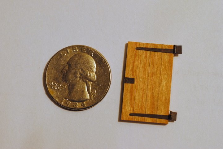
Next up was the door. I figured I'd try to make an actual working scale door, so I started with a sheet of really thin brass and cut the pieces needed. A pin was put through smaller pieces and glued in, so the whole thing kind of works like the pintles and gudgeons of the rudder. I wish I could explain better, but I'm not really up on my door hardware lingo. I think the photos will explain it best..
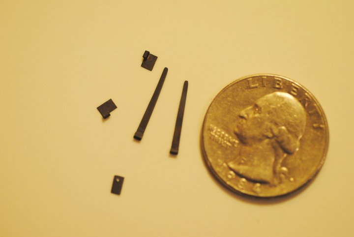
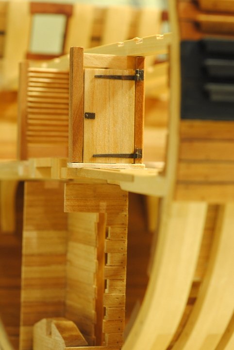
The door itself was pretty standard and both sides can be seen in the following photos of it installed. It's a bit different than what was explained in TFFM, but I'll admit a bit of artistic licence here (pay no attention to my terrible blackening skills)..
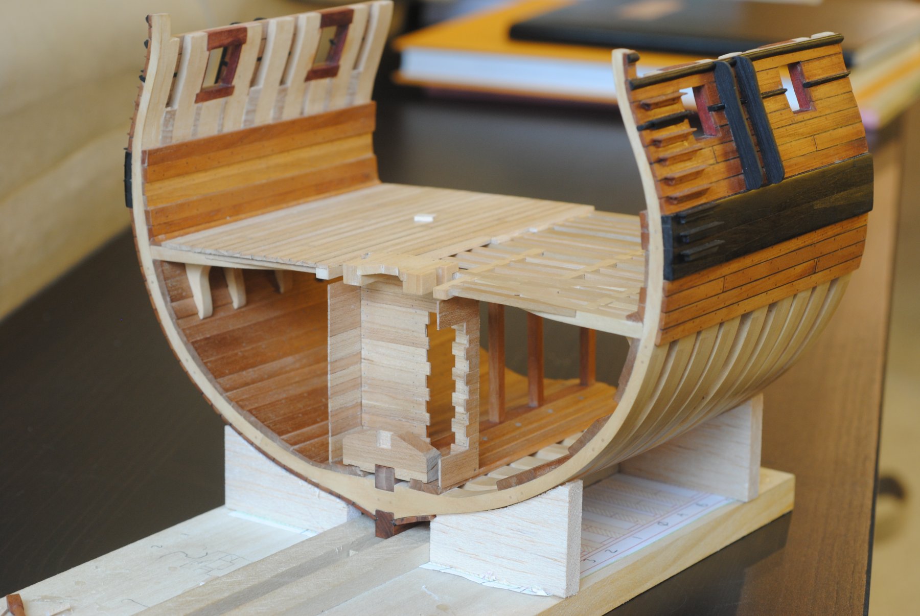
Everything installed (sorry for the yellowness-I'm still frustrated by these damn energy saving flourescent lighbulbs..)
And now into the doldrums of knees, beam arms, carlings, and ledges...ugh. -Chad
-
Gun Deck Beams and Stanchions
Ok-time for an update. I'm actually falling behind in my updates, which is a welcome feeling since it means things have been picking up steam. I tackled the lower deck stanchions, which was my first time using a lathe. I actually bought a Taig lathe bit by bit between 6-12 months ago and it just sat waiting for it's first cameo, which ended up being later than expected .
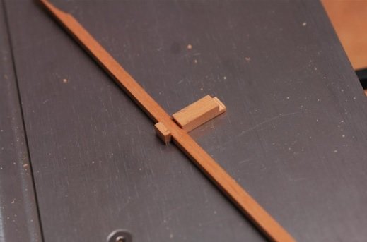
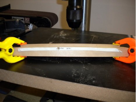
Before I got into the stanchions, I decided to tackle the upper deck beams. I noticed after making the first deck beams that there was a bit of discoloration from the soaking-nothing terrible and only noticeable if you are looking for it-but I thought I'd avoid that and cut them out with the camber. For whatever reason I was scared to death to do this but It was much easier than I expected and my now preferred way of doing it. My first step was to create a jig that would would give me 4 uniform deck beams. The first step was to create two pieces of wood that would have the top camber of the beam.
Before sanding....
.thumb.JPG.90d4a4b56fe3684f5a8bec4a96946d87.JPG)
Then they were lined up so the bottoms would be even and holes were drilled in each side. I used bamboo dowels to keep them even while I sanded down the top camber. I actually did one piece first, then the second, but it would have made more sense to do them at the same time.
Dowelled, one side sanded...
xxpicxx
I then used one of the jig sides made above to trace and cut "blanks" for the deck beams.
Blanks...
Then back to the jig. One of the two cambered sides is glued to a base, and two screws are used to tighten the sides together with a blank in between. If all goes well the blanks should be pretty close to what's needed and only a bit needs to be sanded down.

Jig with a blank
Once the top camber was done, I drew out the bottom camber. I made this little job because I am to cheap to spend 15 bucks on a decent compass
I then cut out most of the extra and made this little jig on the drill press to get the bottom camber. A piece of wood was set the correct distance from the sanding drum and the deck beams were run thru.
This little process gave me some great deck beams. A quick look at the leveling and they were all spot on, so I think I'll be sticking with this process in the future. As for the stanchions, I wish I could explain it well, but I definitely don't feel qualified enough to accurately describe anything that went on with my lathe-I just know I spent most of the first few hours bracing for the inevitable splintered piece of wood to hurtle thru face and disfigure me for life. Luckily that never happened. The only real advice on making stanchions I can give is that the Dockyard chisels I bought to do the notches in the deck beams were priceless. The center column was done easily with the lathe tooling, but the rounded ends were all done by hand. The only photo I took of the process shows how I marked the important divisions in the stanchion-where it goes from straight to donut-shaped, and where it goes from donut-shaped to the chambered of square ends. This helped keep everything the same size. I cut them from longer stock and cut the ends on both sides to the right sides afterwards.
The stanchions were doweled into the deck beams and the deck to keep them secure, and had small pieces of deck planking placed under them on the "open" side for correct height..
The last deck beam is just dry fitted at this point, as the upper well has to be added and supports the beam.
-
Well Mod
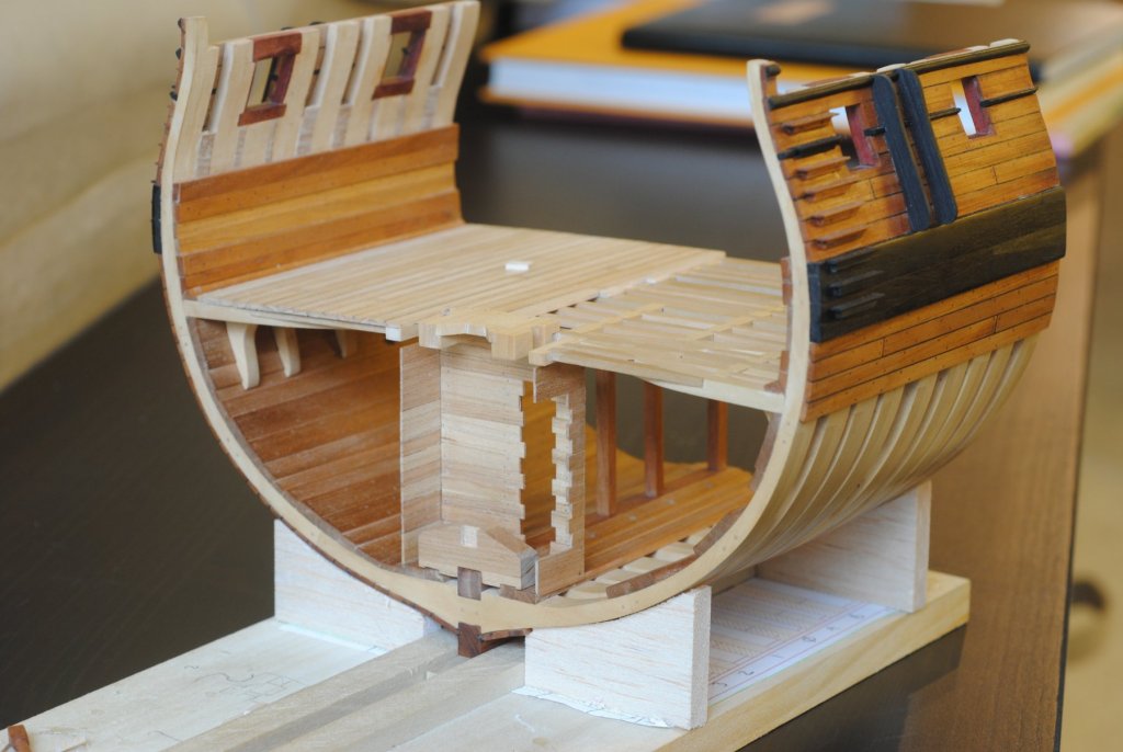
OK- time for another update. I've pretty much completed the modification to include part of the main mast, well, and pumps. I spent quite a bit of time researching it to make sure I got it right- and honestly still don't feel like I nailed it. Either way, I'm pretty happy with the results and think the time put in will pay off when it all comes together.
The first thing I did was research, research, research. I knew next to nothing about mast steps or wells, so TFFM vol 1, Goodwin's Sailing Man of War, and the original Triton drawings that are posted in the stickies section were used a lot. I also pestered Greg and Gary with countless PM's on how things worked- so much appreciation goes out to them! Once I had all the dimensions a pretty good feeling I wasn't about to sabotage my build, I set about undoing some things.
First up was removing the rear center carling and making two carlings that would create the opening for the well and lower partners. This was pretty easy work except for the open deck side not being as sturdy as I would like. It's not falling off or anything, but I won't go putting weight on it..
.thumb.JPG.92053ddbcf6a172fe85a4f4b3fe5c306.JPG)
Once that was done I started on the lower partners. This was and still is somewhat of a point of contention with me. I'm not totally confident I got it right, but this is the point all the research led me to. TFFM and the Triton plans are at odds with which type of partners are used on which deck. The plans show something close to what I have below, while TFFM shows a single piece of wood with holes for the pumps and mast cut into it- which is what is shown for the gundeck in the Triton plans. With Greg's encouragement I went with the Triton plans setup...to a degree. The Triton lower deck plans show a setup that is similar to what Gary used on his Alfred, but looks a bit different. Gary's setup and the setup in Goodwin's book seemed to mesh so that's what I went with. Gary was also nice enough to draw up a detail of how it all went together, which helped a lot. The bolts and nails are all done throughout the mod with brass wire that was cut and blackened (which was a loooong and tedious process, and the reason it took so long..). A notch was cut into the carlings for the hand pumps when the y are later installed, which will allow it to have it's proper angle..

When that was all done, I started working on the partner. The first hurdle was deciding how I wanted to show the mast and partner, since the mast will be protruding aft past the last frame. I ultimately decided on showing a cross section of the partner that will show the mortice that the mast sits in. TFFM and Goodwin were used to find dimensions and I finally got it right on about the 15th try. It was just one of those parts that for whatever reason I just kept screwing up. It actually got to a point where I was laughing at myself as the pile of rejects grew. The "winner" is made of cherry, which I can't decide is what I want to go with. Chances are it'll stay to the side until I'm sure and decide what the mast will be made of (suggestions are most definitely welcomed!)
Finally- the thorn in my side for the last two weeks- the well itself. It's really a simple construction (excellently described in TFFM), but things just didn't want to cooperate. I wasn't able to tenon the stanchions in since the deck beams above were already in place, which made putting any pressure on them nearly impossible. They constantly popped out while placing the boards. Eventually they just came out and everything was assembled separately and placed when it was finished. I didn't want to make it totally enclosed so that the pumps could be seen at least on one side, so I came up with the setup shown below. I also decided it would be a good idea to show the nails. The problem is I drilled the holes not fully realizing how small 30 gauge wire is (REALLY small!) and that most craft stores don't sell it. I ended up spending a few days waiting for it to arrive and a few frustrating nights inserting tiny nails with tweezers. In the end I'm happy with the results, but buy was it a pain in the butt. Also- in the photos below you can see a pin in the keel. This is the bolt that was the stop for the mast step. When the step is installed I'll add the wedges that were driven in between the bolt and step to keep the mast in place.

Hopefully I'm out of the woods and the upper well will be pretty easy. If anything looks wrong or there are any suggestions, please speak up! If I can't change it, I'd love to know for the next build. Deck beams and stanchions are up next, which have already been made so another update should be coming shortly. Although I don't look forward to another round with hanging knees- I think I can the finish line on the horizon!
Chad
-
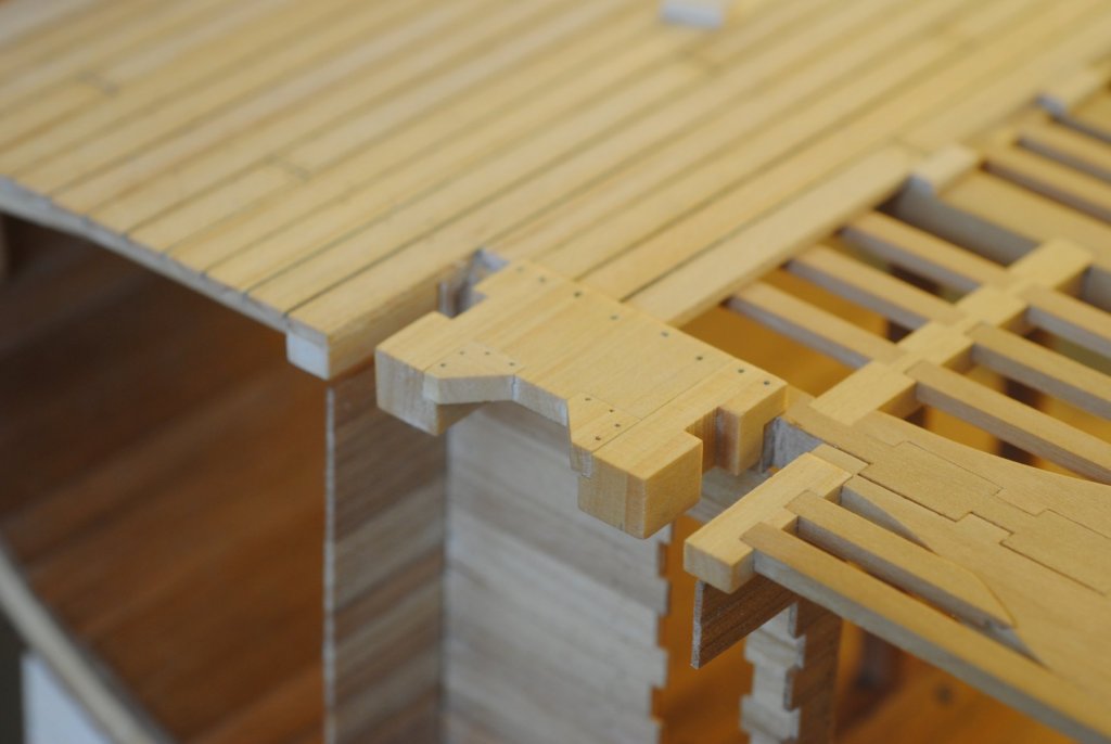
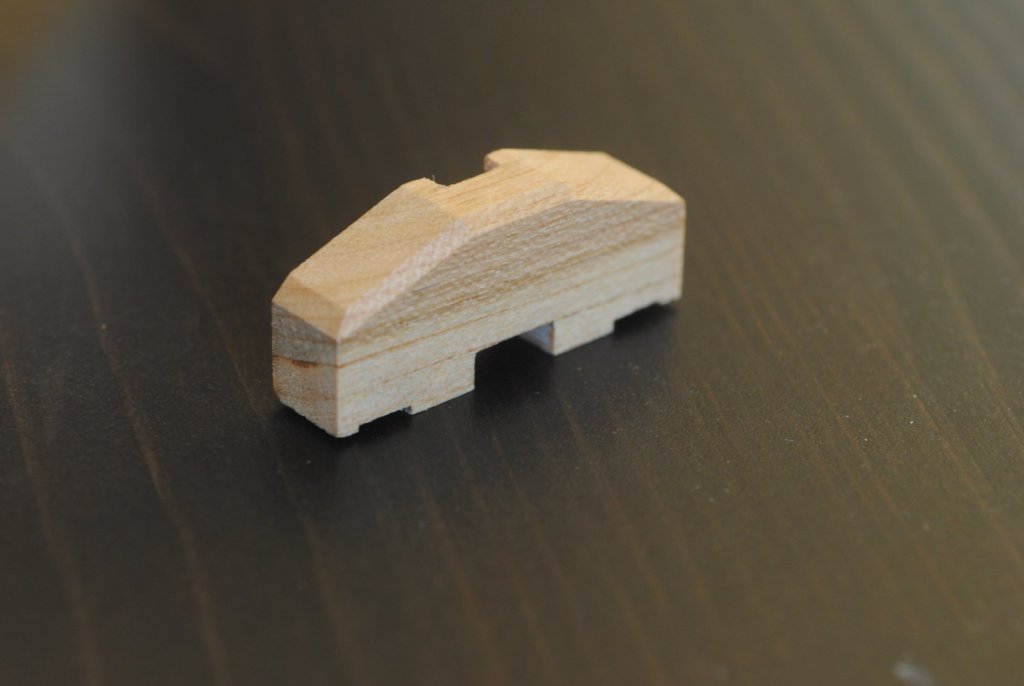
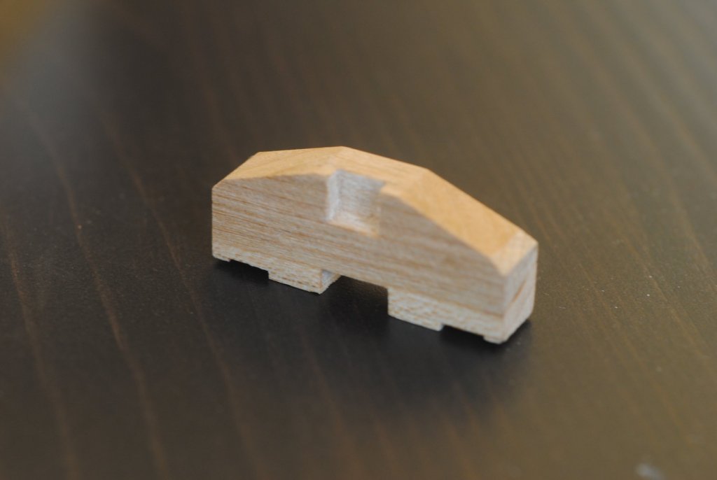
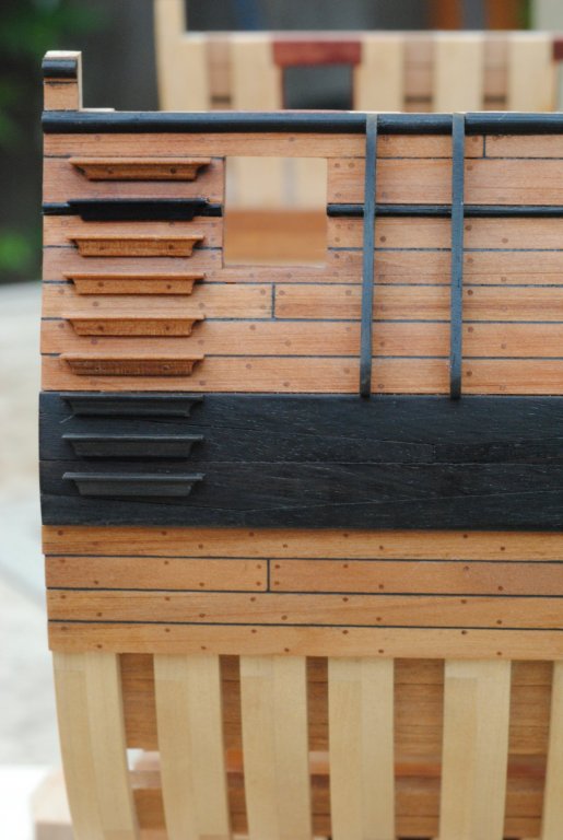
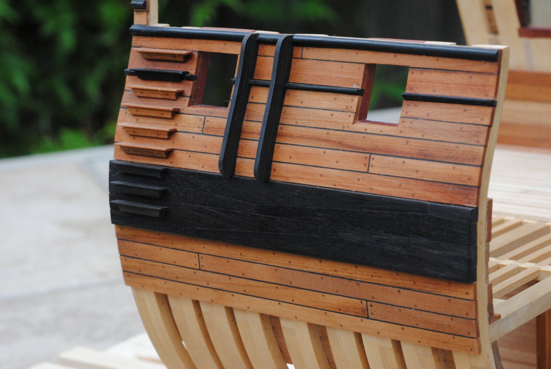
Steps, Fenders, Moulding
I've now finished applying the steps, fenders, and additional moulding to the model. The fenders were pretty easy as the pattern was cut from the plans and shaped for the side of the hull. The only small hitch was cutting a notch to fit over the already installed moulding, but it helped make the decision to install the fenders and then apply the top moulding around fenders, instead of moulding first and cutting an extra notch (I hope that makes sense..). Once the fenders were installed the top moulding was made the same way as thelower one by scraping ebony with a shaped scraper.
The steps ended up being a bit more time consuming as I ended up having to make them twice. I decided to match the color of the steps to where they were fitted, which meant making 5 apple and 4 ebony steps for each side. I started with long strips of the ebony or apple and used a scraper with a rough pattern of the step's cross section. It was important to make sure the steps (actually the strips of wood) were deep enough to make up for the angles that will have to be sanded into the back to fit against the hull and keep the top horizontal. This was the problem that caused me to have to re-make a second set of steps, as the first ones I made were nice looking, but didn't come far enough out from the side of the hull to allow being sanded down to the correct angle. Once I had the scraped strip, I cut the correct lengths for the steps and went about refining them. Chisels helped get the angled sides and files helped with the rest. Then it was just a matter of getting them sanded down to sit horizontally on the hull. I used a cutout of the entry steps from the "Entry steps and Fenders" plan taped to the side to make sure I got the correct spacing. Once they were glued in place I treenailed them in for a bit extra support.

I'd also like to mention that for our fifth wedding anniversary my WONDERFUL wife picked me up Volume 1 of The Fully Framed Model, HMN Swan Class Sloops by David Antscherl. I've seen a lot of people talk about this book and always wondered how good it really could be. Well, let me just say it's pretty incredible. Even if you're not building a Swan-class sloop, much of the information spans English warships spanning the second half of the 18th century. There's many books out there that cover either how things were done or modeling techniques, but not many mix the two. This book does it seemlessly with a perfect balance of the two. The only bad part is now I have to talk the wife into letting me get the next two! I would highly recommend it for just about anyone- well worth the money.
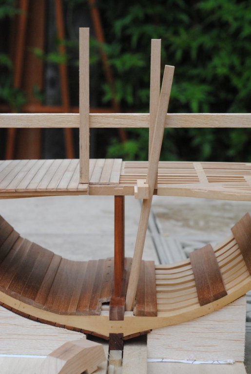
So next up I've started the adventure of adding the main mast, pumps, and part of the well to the rear of the cross section. I've had my nose buried in books and threads here, and have been pestering people with PM's to pick their brain about the subject and I think I have it all figured out and pretty historically accurate (the above mentioned book and Goodwin's English Man of War bounce nicely off each other and have really helped with this). It was tough to wrap my head around the angle of the pumps and where they pop out on the gun deck, so I made a little mock-up, which has been invaluable. I think I'll be able to move along quickly now that I have it figured out, but here's a few photos of my hare-brained plan (some decking has already been cut away and the center carling and open side ledges removed. Rear limber boards were also removed..

-
Caulking
This turned out to be quite the process, but I'm real happy with the results. I used a two part putty called Milliput which I had found in a local hobby shop. I was hoping to use the same type of putty that I used on the decks, but darkest color it comes is the "ebony" color I used, which is more of a greyish. I was looking for black and this seemed to fit the bill.
The caulking was done by mixing small pieces of the two parts, rolling it out like a kid makes snakes with playdough, and pushing it into the cracks like so...
.thumb.JPG.1c403cc223a6115d852be9aa3261da4f.JPG)
I then took a hobby knife and scraped the rest off. Since the wood had been sealed with oil- just as the deck had been- none of the extra putty got into the wood. This ended up being pretty important because as it turns out, Milliput is pretty messy. My fingers were black from just mixing the two parts so I had to be careful with the faces of the frames not to smudge them. They have also been sealed, but I didn't want to take any chances seeing as there's no replacing them now. Once the excess was scraped off, I used some spirits on a rag to just wipe any little smudges were left. The next day it was sanded down, cleaned up, and oiled again.
Like I said- I'm really happy with the product and glad I did the experimentation (you never know until you try..), but it might be too much risk on a full hull. –Chad
.thumb.JPG.523cd511f34c5909039c516b8948d075.JPG)
...On one last note- I dug out the jig I used to set the frames and added some small scrap balsa blocks to the bottom to use as a cradle for work from here on out. "Uwe's Jig" was starting to show it's age from all the handling, and it was getting a bit tight with the outer planking on now.
-
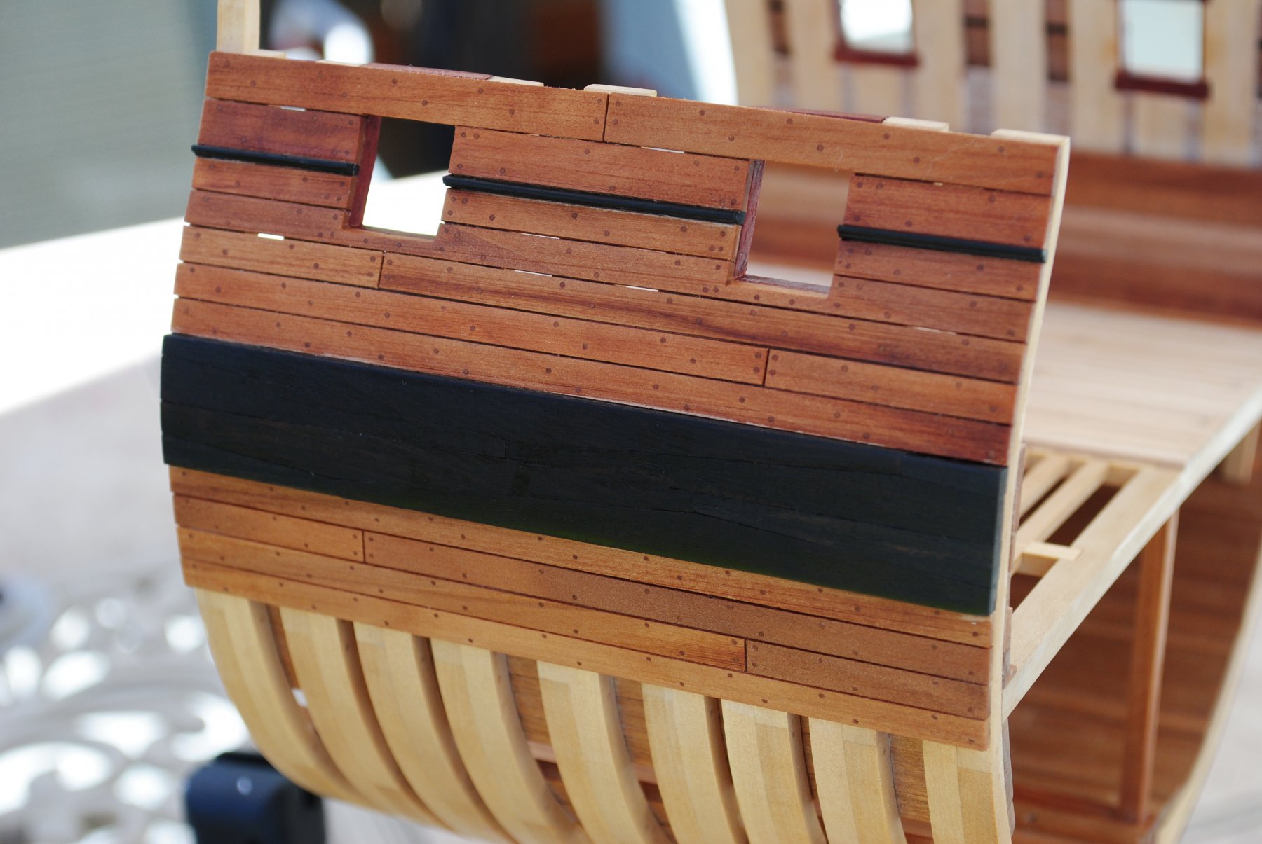
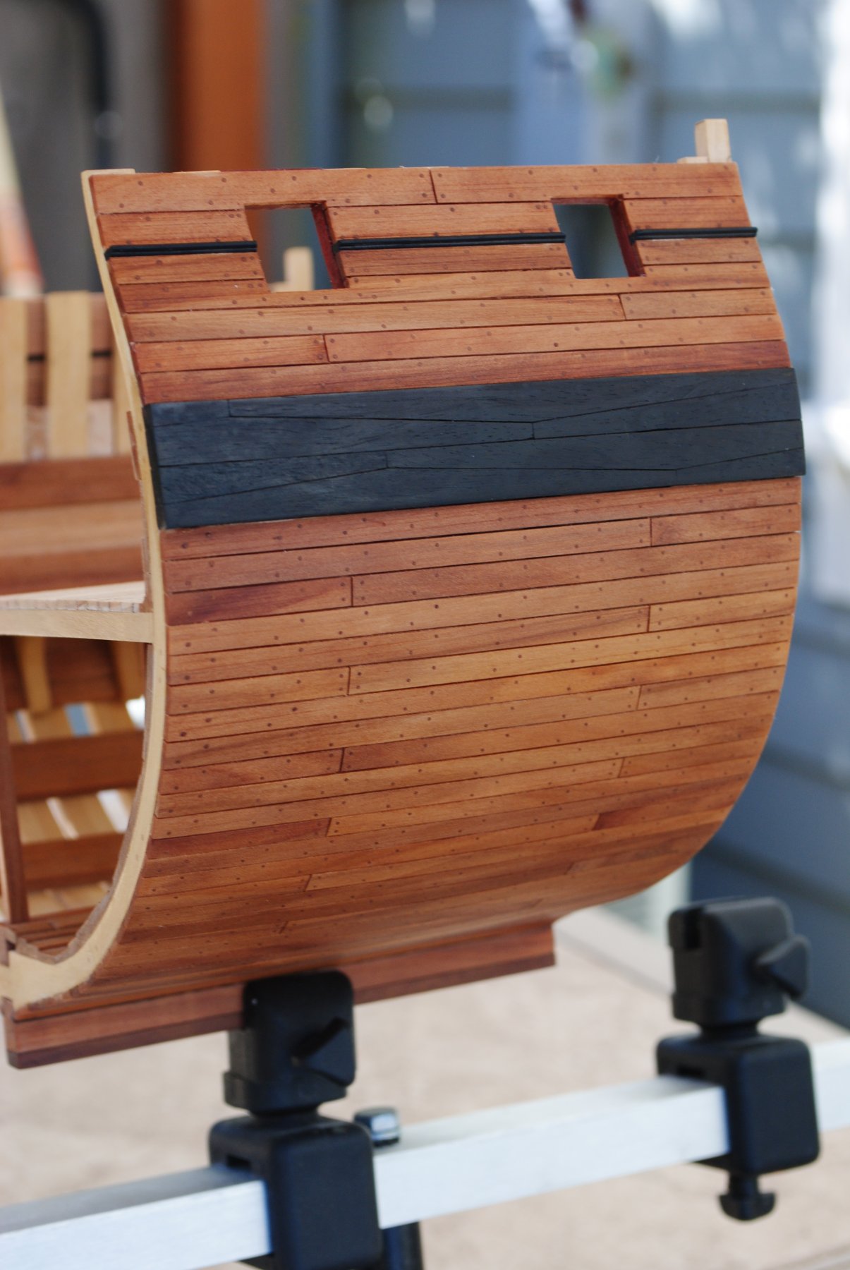
Planking
The thick stuff was done with apple and the center planks laid in cherry. Trennels were done in the corresponding wood.
Outer planking was done in apple with apple trennels. I still have a bit of cleaning up to do, but everything was oiled with pure tung oil, which will protect the wood from staining when the caulking is added- similar to the procedure I used with the decks. I started the spacing using metal shims, but then after about the second planked moved to eyeballing it. Probably a dumb thing to do, but it came out pretty good. The moulding was done with the ole' scraper trick where the profile was ground out with a dremel on an old razor blade. This was a lot easier than expected. –Chad

-
Deck Planking
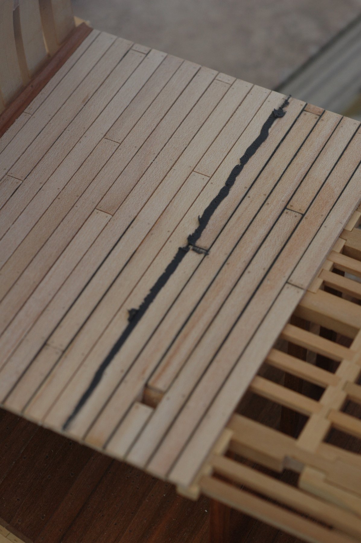
As I've said before, I'm using this build just to experiment with different ways of doing things- whether it's something I just haven't tried before or some hare-brained idea that pops into my head that could possibly ruin all my hard work. So for deck planking, I wanted to try a different caulking method than I've tried in the past. I've only tried the construction paper method and I wasn't too keen on the result, although I chalk it up more to my inexperience than the process itself. This time I decided to try John0868's method of using putty for the seams, since I really liked the look.
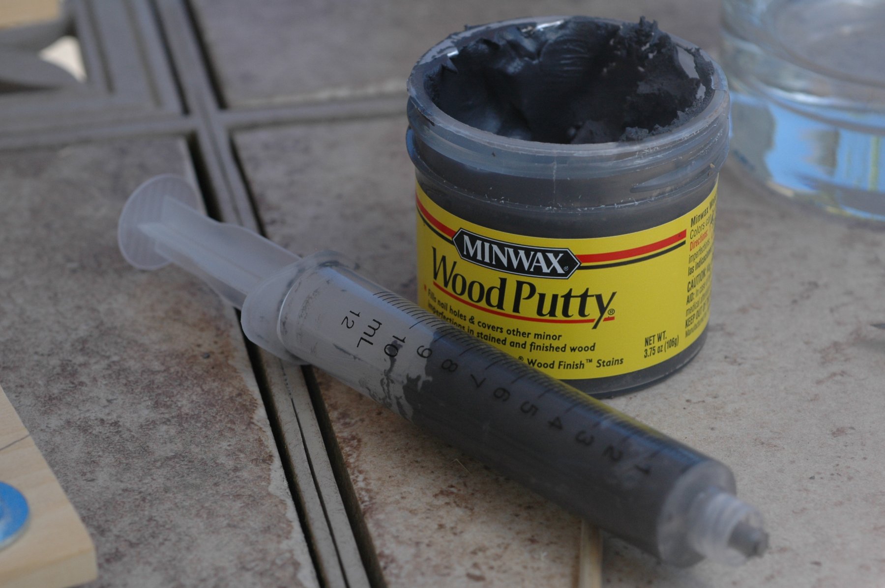
First step was to find a product that fit the bill, so I actually picked out a few different ones and rant hem thru a small mock-up to see how they looked. long story short, I ended up with Minwax ebony colored wood putty and a syringe that came in a set I bought from Rockler woodworking for inserting it.

Next I started laying the planking, which was done in Maple and set the spaces for the putty using a metal quarter mm shim. I also used the four butt shift shown in Goodwin's book for the planking..
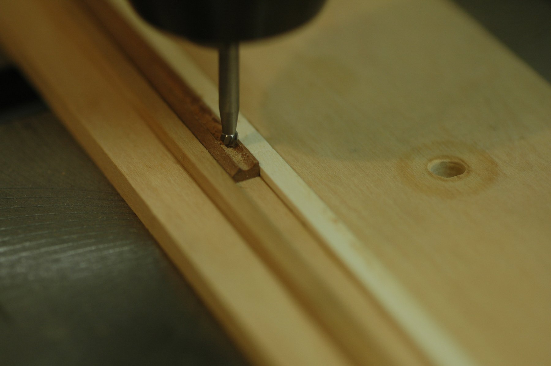
Once the planks were laid from the centerline outwards, I had to make the waterway. I used the concave design found (again) in Goodwin't book. It shows the edge that sits against the bulkhead to be at a 45 degree angle and the side facing the planking to slope down to the planking in a concave manner. The 45 degree angle was sanded down on a disc sander and a jig using the drill press and a small dremel bit used to cut the concave side..

..the waterway was just pushed thru and then the jig board was adjusted to take off the remaining lip. It was then finished by hand to clean it up. Overall it worked well, but the bit I had was a bit too rough and left some slight gouges. Luckily they can really only be seen if you are looking for them.
Once this was laid, the deck was treenailed and covered with a wax paste (the waterway was finished with tung oil) to seal it before inserting the putty. This was a really important step because otherwise it will stain. Treenails were done using maple and apple for the waterway (which was made from apple). Once thing I've gotten from this build is that I love the way treenails made from the same wood as that they are going into looks. It can be a bit more trouble to pull some hardwoods but well worth the trouble in my eyes. Laying the putty withthe syrings was a bit of trial and error, but I found leaving the syringe tip off and just holding it tight against the deck while pushing it in worked best. Getting closer to the sides got tricky, though. Once I laid a line I used a razor to just scrape the excess off and then a rag to get any residue..
When everything looked good, I gave it another coat of wax. Overall I really liked the way it came out and looks with the maple. I can see how it would be a bit troublesome on a full model, so the verdict is still out on if I'll use it on something besides the cross section.
The "finished" product...
-
Ledges and Lower Deck
So I finally finished the lower deck, which was tedious to say the least. I basically followed the plan I laid out in my last update, except nothing was actually attached for good until the end. There weren't any progression photos taken along the way since I needed to buy new memory cards (got to old and kept erasing pictures..), and it was 7 months, so I'm just going to list as many helpful hints as I can about the process of making ledges, hanging knees, and lodging knees..
1.) It's a close call, but I think moving front to back (or vice versa) is easier than making deckbeams, then carlings, then ledges... as it starts getting a bit hairy if you need to get into some of the tight spaces. I came to this conclusion when I needed to widen some of the notches on the beam arms. I ended up mangling a couple pretty good.
2.) Hanging knees will crush your soul. It took me a loooong time to finish them, as it seems you sand a bit here, sand a bit there, get close to a perfect fit- them over sand something and have to start over. AAARGH! The hard work pays off when you get a good fit, though. I found it best to leave the tops a bit long and just sand them down when all is said and done.
3.) I had boxwood from two different suppliers, and both were separate colors. I used both so now I have assorted colors- I'm going to order a new set of boxwood before I do the top deck.
4.) The small chisels I have (2mm? Have to go back and look..) are pretty good for most of the work, but some of the notches on the lodging knees have a long cut. I think a bigger set of the mini chisels would be better suited.
These are the main things I can think of now. Hopefully with a new memory card and some easier work ahead, I'll be able to update more. Here's the deck, sanded to 400 grit and finished with a wipe-on poly...
-
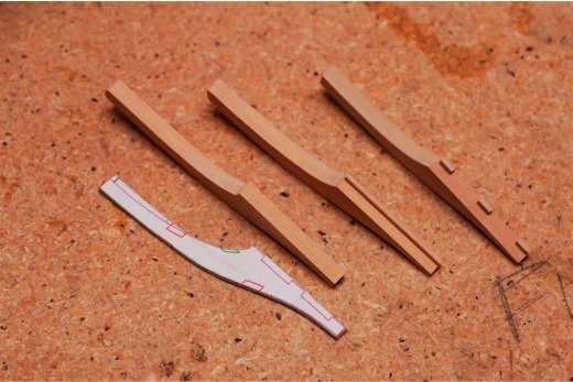
Beam Arms
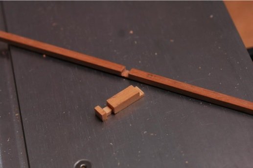
So the first thing I had to tackle after the deck beams was the beam arms. They turned out to be harder than I expected and I went through quite a few before getting four good ones. The first problem I had was when using the drawings as a template to cut them, I found that I had lost about 2mm off the back end of the model- so the beam arms stretched too far aft. After a thorough search of the workshop floor for the missing 2mm, I decided I'd just have to redraw a template for the beam arms. In the photo below you can see the redrawn template (the inboard purple line shows the original arm curve) along with the three steps to making the arms. First the cutout which was sanded to fit, then a step was made by running it along a table saw with the blade set to the correct height (the width and thickness is determined by the notches cut in the deck beam). Finally the tabs (I'm not sure what the correct terminology would be) were carefully made using chisels.
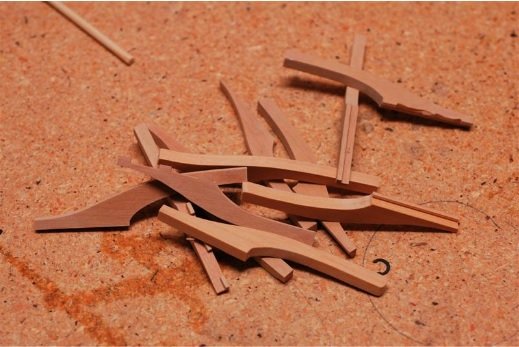
As I mentioned- there were some screw-ups. Enjoy a slice of my humble pie
Once they were finished, the notches for carlings were cut, and finally carlings made. Carlings were a fairly simple process- I just used the table saw to cut the small ledge that conformed with the notch cut in the beam arms. It was all installed and this is the final product..
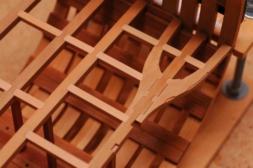
Let me clarify something I wrote- the carlings were a simple process, but not necessarily a simple process to carry out. There were a couple I wasn't entirely happy with, but it had more to do with the notches in the deck beams. I didn't cut the full notch before installing the deck beam- just did a rough cutting. Then after they were installed I cut out the rest, but if I over cut (I did) or had made it a bit off center so the carling isn't totally straight (I did) it can a be a bit frustrating to look at. Luckily it's very slight and I can live with it, especially since most will be covered with deck planking anyway.
OK- so the other thing that has been slowing me down was trying to come up with a solution to the rear deck beam that had to be added after the drawings were made. I really didn't care for the idea since it was one of those things that wouldn't be done in real life and I didn't like the look of. The problem was coming up with something that would support the aft section, since the carling and ledges would probably sag if made the normal way. The idea I came up with was making the ledge run all the way from beam arm to beam arm in a single piece, but needed a way to have it look as if it's two separate pieces. I honestly have no way of describing it, so hopefully these photos will kind of explain what I did.
The bottom of the carling will have a small plug of wood installed to finish the illusion. Here it is loosely sitting in place. I need to finish the notches for the bitts before totally installing..
So next it's on to ledges. –Chad
**Note from Future Chad… this crazy carling and ledge was removed for the well mod. If you are attempting to follow my log for building purposes then read the “Well Mod” post before following my cockamamie idea above!
-
Deck Beams
So I had posted a while back in the deck beam camber thread about soaking and bending the deck beams instead of cutting them at the correct camber, which is what I ended up doing. I found it worked pretty good , but took some refining to get them to not spring back (which was possible). I started with the correct dimensions of lumber for the deck beams and cut them a bit long so I could sand down the end eventually to fit them. After that I placed them in a tub of water and soaked them until they stopped floating- this gave me an idea that they were fully soaked, which took about 12 hours. I then took a block of wood and sanded down the surface to the proper camber. This was done by sticking a cutout of the deck beam from the plans on the block and sanding. Then the deck beams were centered and clamped on each end...
Since the weather has been nice and hot, I just left them to dry outside for about another 12 hours or so. This usually did the trick- but one or two I resoaked and rebended. Another way I tried that worked real well, was bending the beams over the block then submerging for 12 hours, afterwards drying. I was only able to try this on one beam, but it worked real well.
After bending, I marked a rough centerline on the beams and sanded the ends to fit in place on the model. Once I had fitted beams, I marked the exact centerline down all four and another line off to the side. The second line was purely my neurosis at first but ended up being really important. Next I cut out the deck beams from the 'Cross Section Lower Deck Layout Pattern' and lined up the centerlines and taped it down. This then showed me where all my notches for the carlings and sheet bits would go, and should line up perfectly with the other deck beams. I then started chiseling out the notches using a set of Dockyard chisels, which someone here mentioned. They suit their purpose well and I've been really happy with them.
If you're interested... http://www.woodcraft.com/Family/2001361/DOCKYARD-Micro-Carving-Tools.aspx
Once everything was chiseled out (I just decided on a depth of about 2mm, I think), I checked the alignment by putting all the beams back on the block and lined them all up using the extra line I drew (the centerline has been chiseled away in some spots- hence the use of a second line ). I was able to make any small adjustments needed to have nice straight carlings in the near future.
When that was done, I installed the deck beams. First I used the same plan as above and cut out a strip along the center carlings with the centerline and laid it along my keelson. Then at the center of each deck beam
drilled a small hole where my pillar would go. I also flipped over the deck beams and drilled another small hole along the centerline. Then it was just a matter of making up the hold pillars (easy stuff by now ), drilling a small hole on each end in the center, and using small dowels to put it all together! One other note here- I made a game time decision to change from cherry to apple for the pillars- just seemed to let the colors flow better. The only other part that could be a little tricky was making sure the beams were exactly perpendicular to the CL. This was done be setting the forward-most beam and progressively setting each one after- making sure the hold pillar is straight and using a ruler to measure the distance between the set beam and the one being set at different spots (I hope this makes sense!). Finally I had my lower deck beams in place!

-


.jpg.1f0a89d61b7bafde46cb930fee108d1b.jpg)
.jpg.2a7811bb2b8de0c8f439b58533a8dac8.jpg)
.jpg.cdf0bac67e521865b6af09f3400b7858.jpg)
-2.jpg.97e836139618aca3a0108892f0f19da4.jpg)
.jpg.c54604b4a2f5869c2623fcbf3a884b5c.jpg)
.JPG.6f3b43afbceee1f86995c8c81e27ce54.JPG)
.JPG.4128a4062fdcb4691868f9e9786d2b65.JPG)


.JPG.2f071e7f6c836def56f490390a4417c9.JPG)
.JPG.5baae8d1c9f5db6b693fa51ac023f9cd.JPG)


USS Spruance DDG 111 by RGL - FINISHED - Trumpeter - PLASTIC
in - Kit build logs for subjects built from 1901 - Present Day
Posted
Greg, your model is fantastic and took me down memory lane! I was a SPY radar tech on the USS Barry (DDG52), so many of your photos bring back lots of memories. Fun fact- those SPY arrays are made up of a thousand or so small porcelain windows that are covered in RTV. When you go through a hail storm lots of them break and you get to spend a day in port on a ladder replacing them! -Chad