HOLIDAY DONATION DRIVE - SUPPORT MSW - DO YOUR PART TO KEEP THIS GREAT FORUM GOING! (Only 13 donations so far - C'mon guys!)
×


Charter33
-
Posts
455 -
Joined
-
Last visited
Content Type
Profiles
Forums
Gallery
Events
Everything posted by Charter33
-
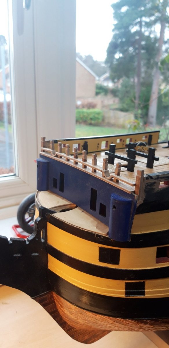
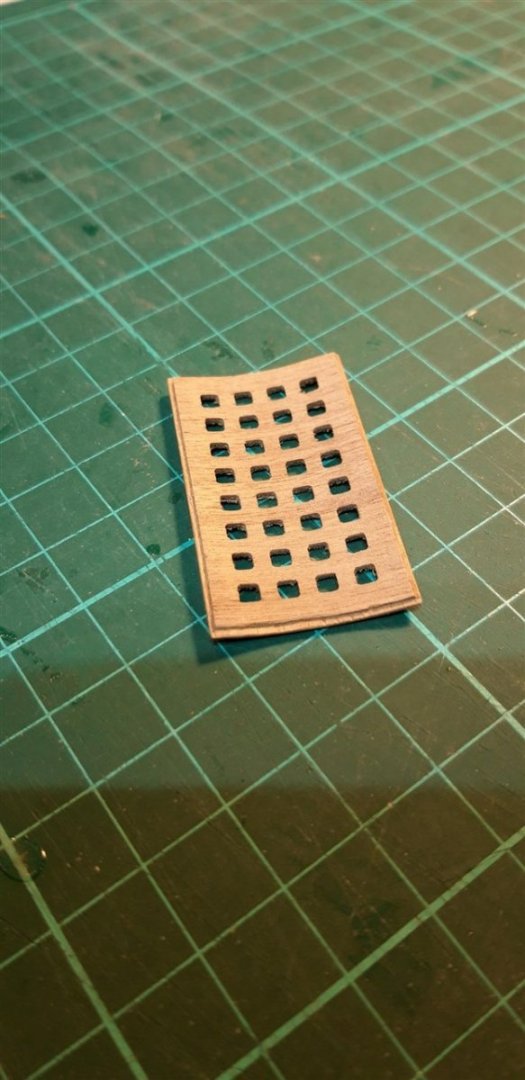
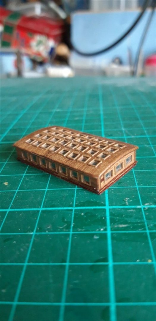
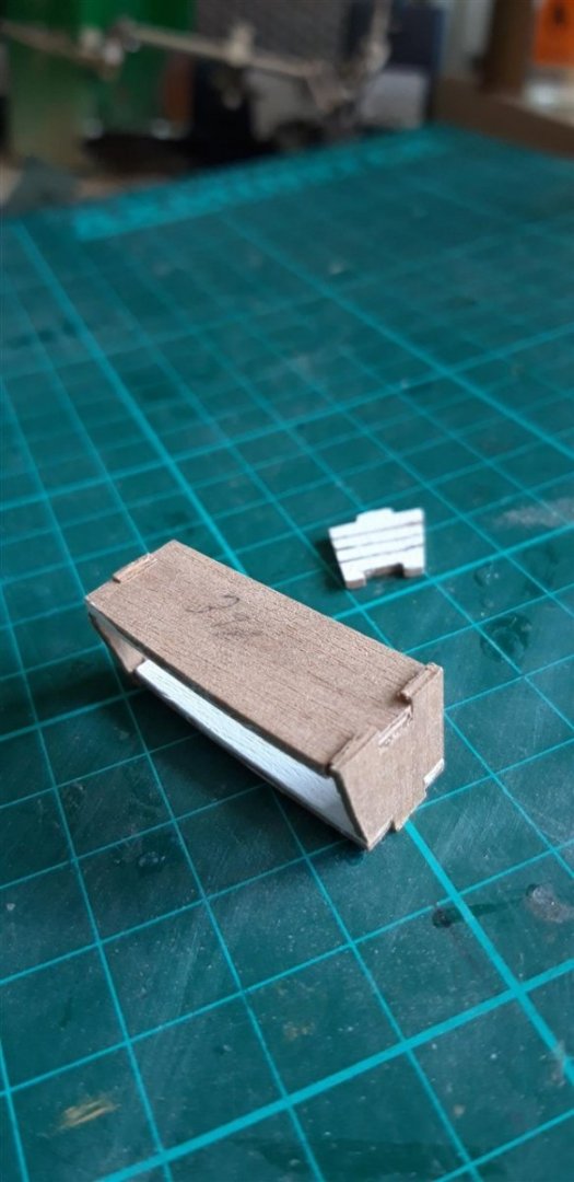
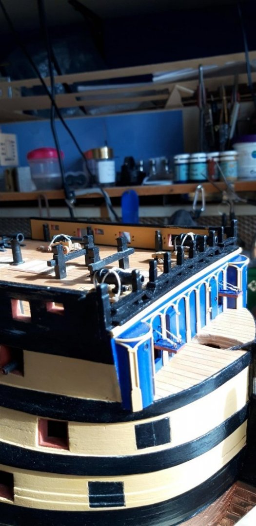
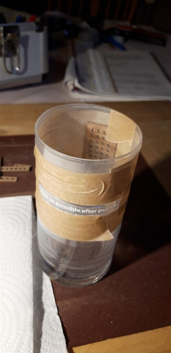
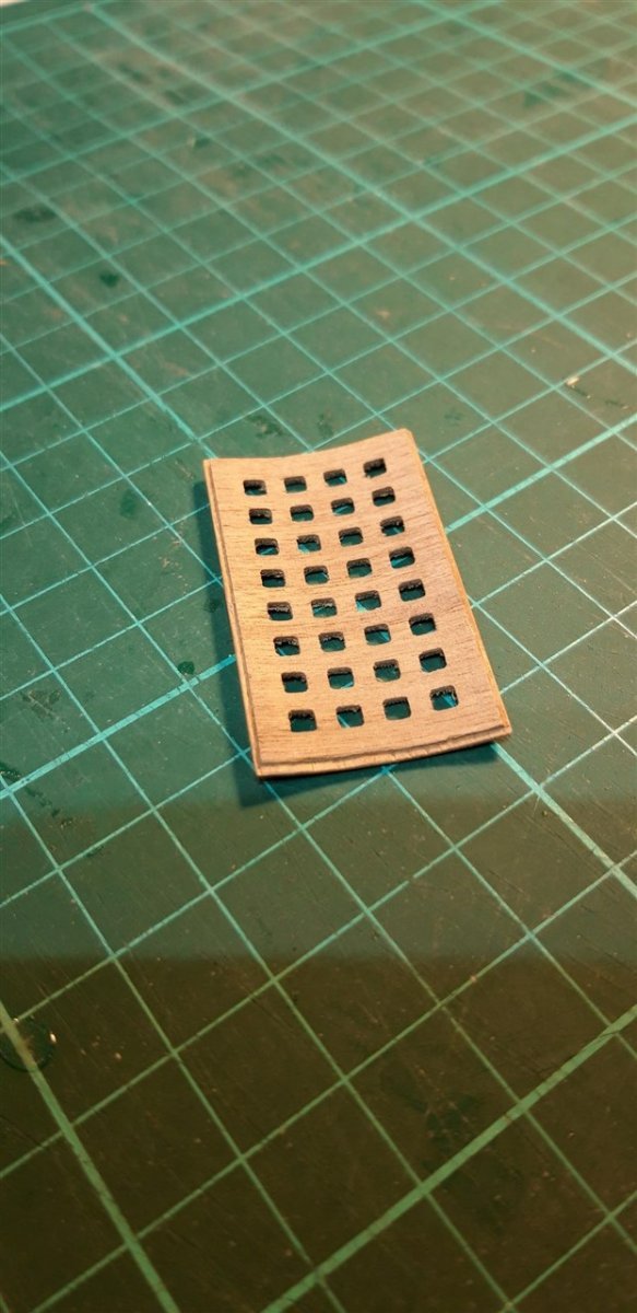
Thank you Robert for your kind comments, and for all the other positive reactions my last post received. Constructing the flag lockers and the skylight proved a bit more challenging than I expected, although those with the latter were, admittedly, self inflicted....... Assembling the shelving for the flag lockers went alright but I had problems with the carcases which seemed too big with gaps on both sides and top and bottom when the shelf assembly was dry fitted. Grooves are provided on the inner surfaces of the side pieces for the shelves to fit into and my initial plan was to cut down the shoulders of the carcase joints to reduce these gaps. It was clear, however, that by doing this sufficiently to get the shelves to fit in the grooves would result the size of the left and righthand vertical shelf spaces being noticeably smaller than the rest. My solution was to re-make the ends from scrap ply without the grooves. Once finally assembled and painted the overall length of these units still matched the size shown on the plan. Additional tapering plinths fitted under the outer half of the base to improve the fit on the deck. Installed with the inner and outer transom knees, ensign staff support and Horse. Comparing the design for the model's skylight and pictures of that on the full size version there was several differences, the biggest being the curved roof of the original. To achieve this the roof part in the kit was soaked briefly in hot water, bound with a strip of polythene and masking tape around a suitable mould - in this case a drinking glass, with parallel sides, zapped in a microwave oven for 30 seconds, and then left for a couple of days in the airing cupboard. It worked..... There is more of a decorative moulding to the edges of the roof as well and this was achieved by cutting away the lower layer of ply on the underside..... the tops of the end pieces were shaped to match the curve and the top edge of the side pieces was bevelled prior to assembly. The Pre-painted brass window frames were glazed and fitted before this assembly stage. Finally additional twin mouldings were fitted to the lower edges of the sides and ends (the upper one curved here} and the whole unit given a coat of matt varnish before gluing onto the deck. At this point the other poop deck fitting such as the various cleats, snatch blocks, Kevels and the Mizzen Topsail Sheet Bitts were added. Cheers, Graham.


_1280.thumb.jpg.d50252f8915d620b2c92cd5897d50d2f.jpg)
_1280.thumb.jpg.029d031ed36ef22ccd2e53d69760bc9c.jpg)

-
Looking forward to seeing how this challenging project progresses. Looks like it should be a real cracker! Good luck.. .
- 194 replies
-
- 3
-

-

-
- Bottle
- Treasure Fleet
- (and 3 more)
-
Beautiful model .... congratulations on a true work of art!
-
This was just posted on the BBC News website (sorry, my I.T skills are not good enough to add those clever 'links' 🤪!), and thought it worth sharing https://www-bbc-co-uk.cdn.ampproject.org/v/s/www.bbc.co.uk/news/uk-england-hampshire-61637171.amp?amp_gsa=1&_js_v=a9&usqp=mq331AQKKAFQArABIIACAw%3D%3D#amp_tf=From%20%251%24s&aoh=16540675428704&referrer=https%3A%2F%2Fwww.google.com Hope this works..... Cheers, Graham
- 3 replies
-
- 12
-
-
-
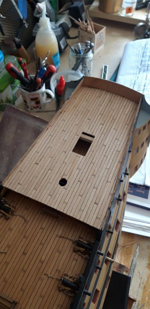
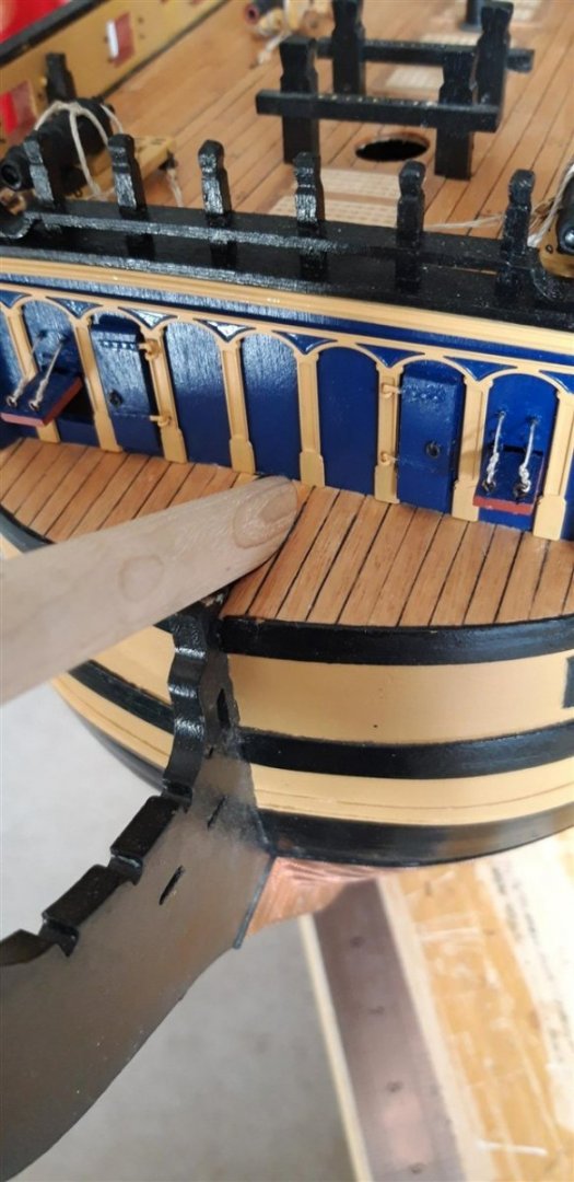
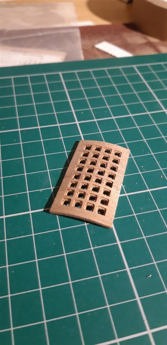
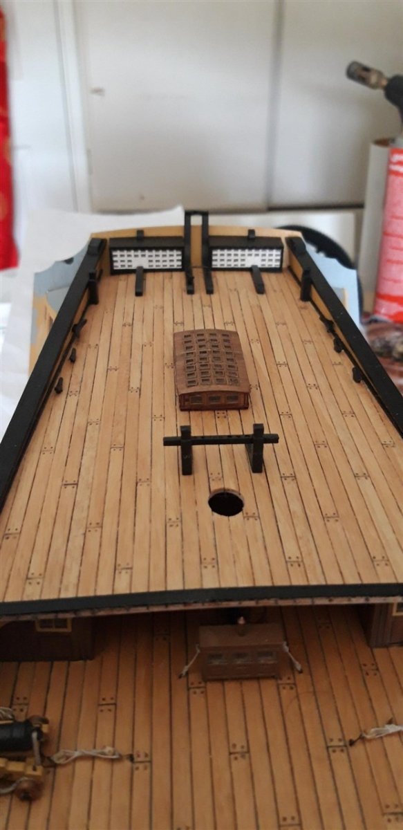
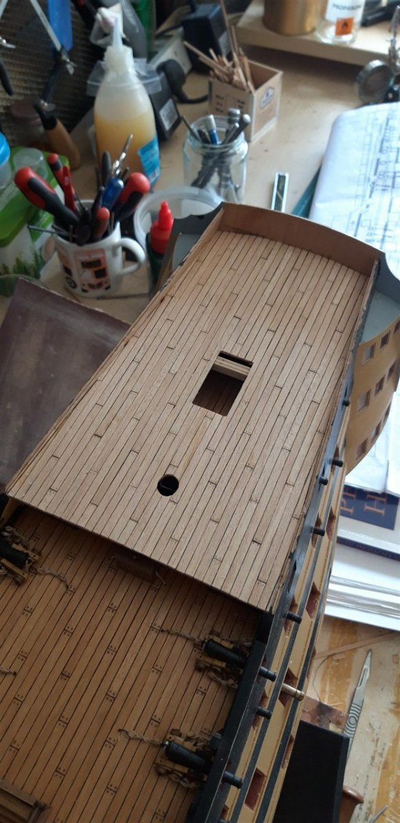
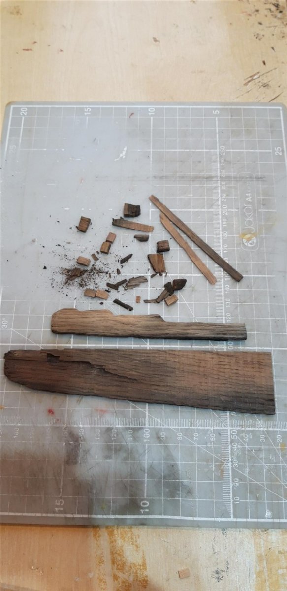
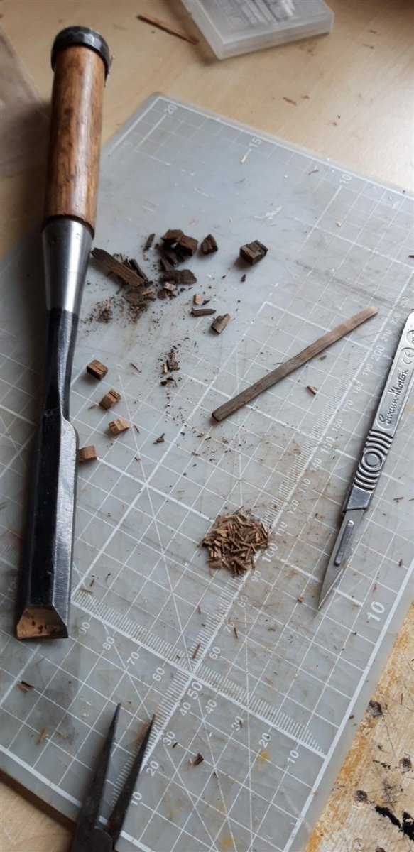
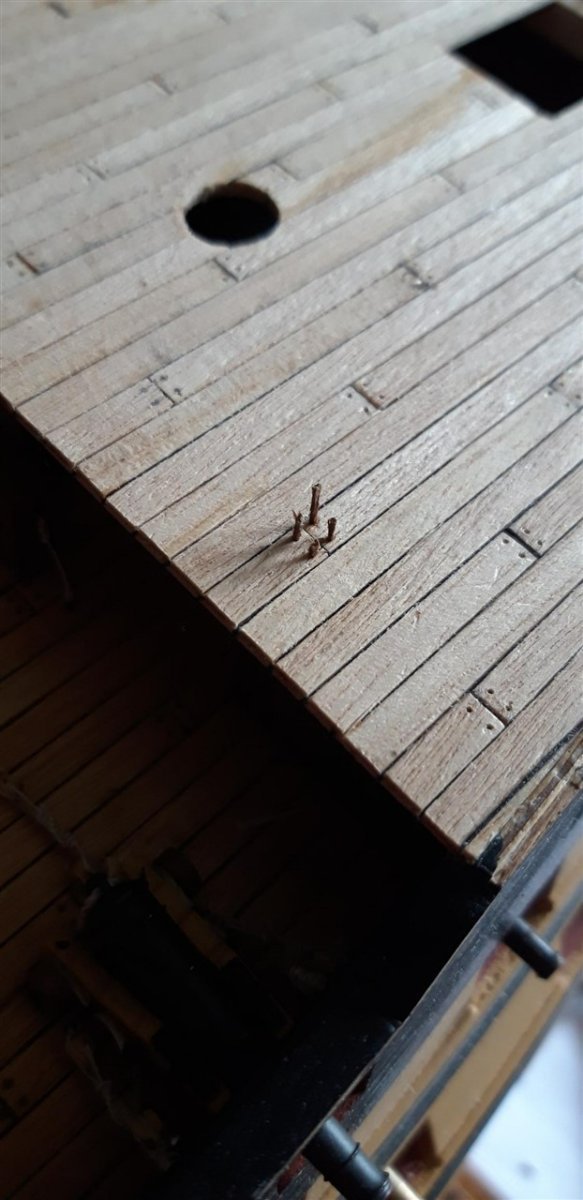
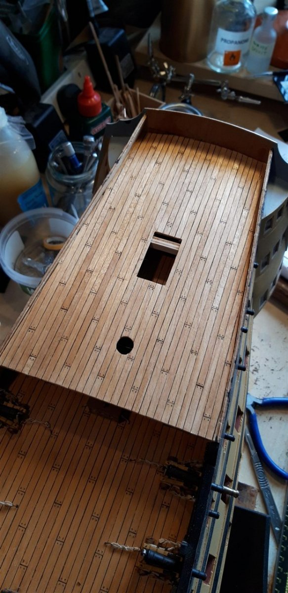
With the fitting of the Poop deck ply it was time for the last section of deck planking for this model, using the same technique as on all the other decks, black thread calking etc. Planking did not go according to plan, however, and it quickly became obvious, half way through laying the starboard side that there was a distinct kink in the plank line developing. With this particular section of decking being very open to view there was no other choice but to rip it off and start again! Planks were fitted to the same pattern as before......... with the position of the treenails impressed where required. The only difference with this deck was the choice of material for the treenails. Where I had previously used slivers of teak veneer this time I used certified oak sourced from wood recovered from restoration of the original. Way back in post #9 I described how I replaced the walnut rudder that came with the kit with this alternative. Loathe to throw off-cuts away I have saved as much as I could .... The larger piece at the bottom of the picture is destined to be incorporated into the display cabinet for this model as will a piece of original copper hull cladding. After reducing some pieces of oak to fine 'splinters' these were individually carved to shape with a scalpel and glued into place in the pre-marked holes that were by now drilled to 0.5 mm diameter. The failure rate was noticeably higher than the previous material, with the oak being far more brittle and difficult to work, but if they survived the scalpel they were usually strong enough to be glued in place. Once trimmed down the whole deck was cleaned up with a cabinet scraper and the given a couple of coats of matt varnish. The bulwarks have now been lined and attention moves on the the Poop deck fittings including the flag locker and the skylight, the latter of which looks like it provides an opportunity for a bit more 'bashing'...... Cheers, Graham.


-
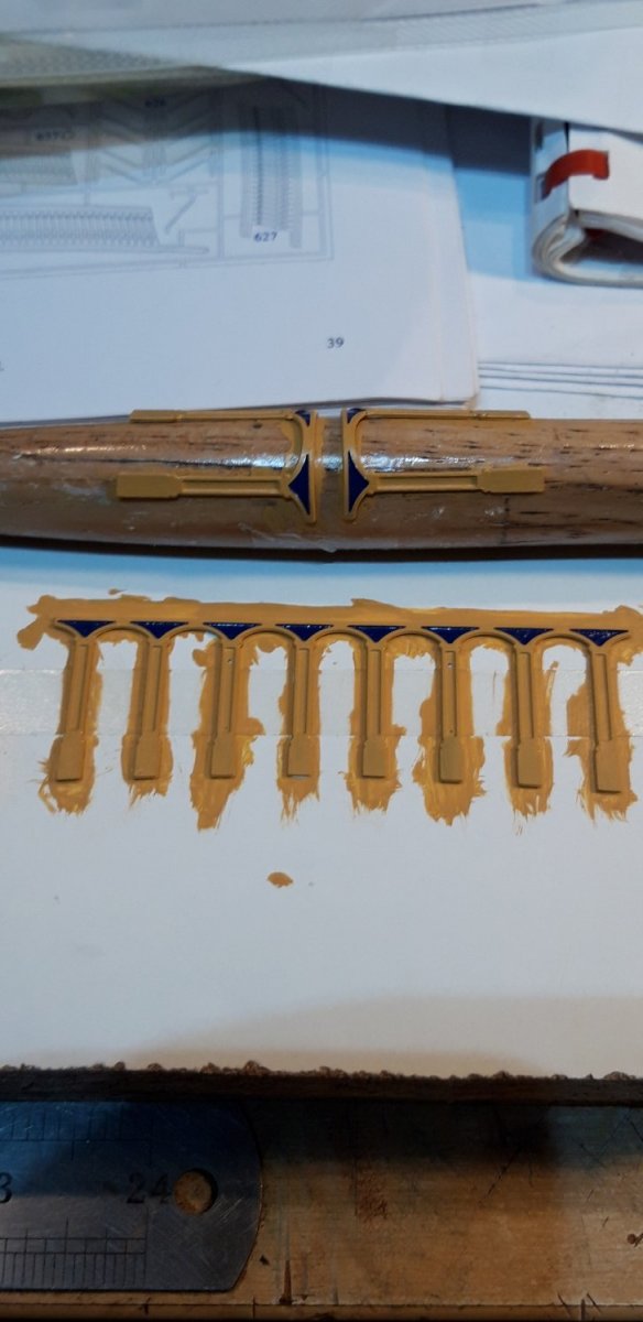
Hi David, Your plan to plank the round houses that way will work, but just a 'heads up' with regard to your last sentence - I found that the top edge of the wales needed trimming lower (only under them) to get a good fit as the round house extends through them and overhangs a little. Your build is progressing impressively! Good luck, Graham
- 218 replies
-
- 2
-
-
- Victory
- Caldercraft
- (and 1 more)
-
I know I've used this phrase before, but:- Superb!
-
Just gorgeous......
-
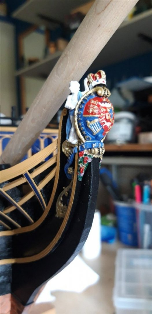
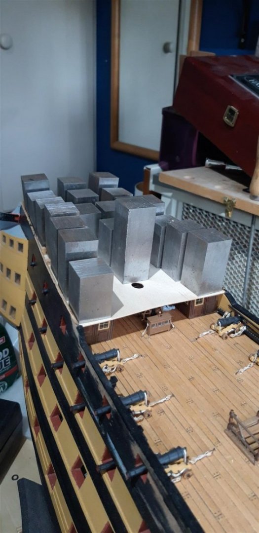
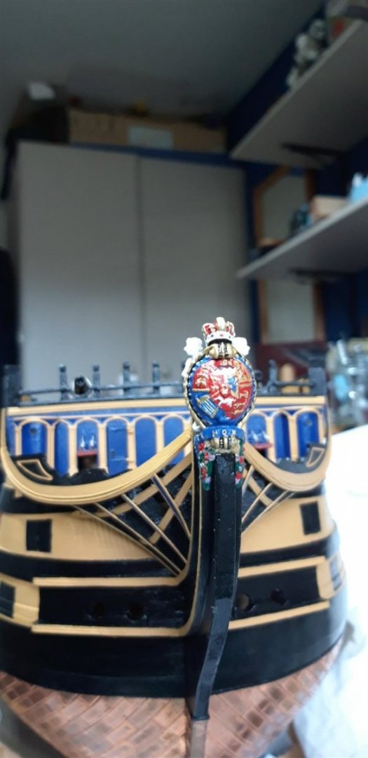
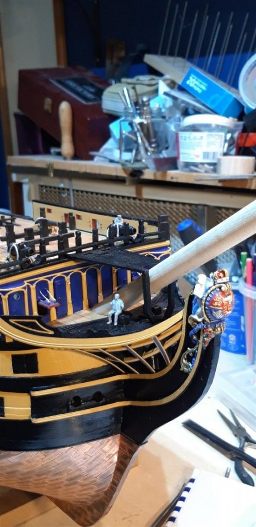
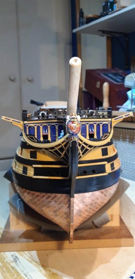
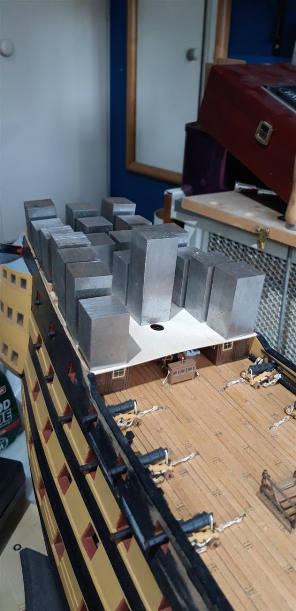
Had a good session in the shipyard today...... Started by modifying the slot in the stem to improve the fit of the main figurehead casting This went well and closed the gap between the lower 'rose and thistle' section and the bow curved rails, as this picture shows....... just dry fitted ..... I then went on to fit all the figurehead castings with rapid drying epoxy adhesive, Construction of the Cat Heads was fairly straight forward with the only problem being my inability to locate the 5 x 0.5 walnut strip for the two middle longer pieces that form the lamination. The parts list says there should be one strip, but repeated searching through the timber supplied failed to locate it. In the end I resorted to sanding a short length of the 5 x 1 strip that is used for the rest of this assembly down to the required thickness using a sanding block and a pair of old hacksaw blades either side of it as thickness guides. Here both are made together with the cleats, and here they are painted up and ready to fit While they were drying I skipped ahead and added the poop deck using my stock of weights to hold it down until the PVA had dried, and then went on to paint and fit the Marines Walk The Cat Heads were by now ready to be glued in place Just the curved brass decoration left to add to the bow now, but it's a little late this evening to start metal bashing.......... Cheers, Graham.


-
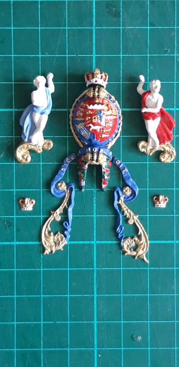
A quick update - the figurehead castings together with the Cat-Head decorations have now been painted. With my phone contantly set to Google images, many touch ups and endless alterations, I'm now calling these ready for eventual fitting. At one stage I was reduced to using the proverbial one-hair paint brush..... Right - on with the Cat-Heads..... Cheers, Graham

.thumb.jpg.1dc39efe6be4e2a696e4d6c7484a1e7c.jpg)
-
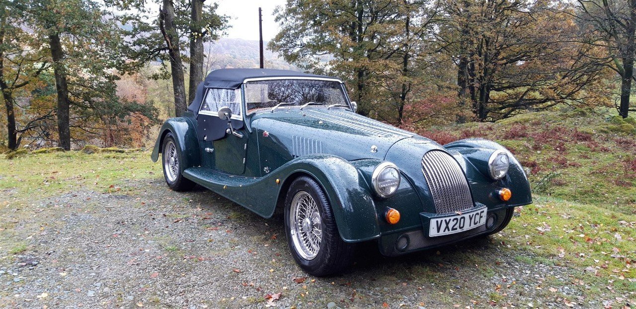
Yes Shipman, with hand built cars like the Morgan every car is pretty much a prototype and idiosyncrasies are in-built. As for bought in components, our car was BMW powered, but can't fault power or handling. Wet weather is not the best environment for a Moggy, love to own one but a lottery win would be required first. A biker too, 850 Norton Commando, so very familiar with the joys of riding in wet trousers or with a frozen 'tash' 🥶😄
-
Oh, they are still making them, in fact they re-launched a ground up re-design last year - fabulous! Hand on heart the Morgan factory tour in Malvern is by far the best that I have ever been privileged to experience, with the Biggin Hill Spitfire factory and the MacCallum Distillery tours close second. I have not (yet!) had the pleasure of driving the three wheeler, but when Covid scuppered plans to celebrate 40 years of marriage in Asia the Admiral and I decided to tour the Lake District in this beast, the new plus 4, hired directly from the factory.... Totally impractical for a torrential late October week in Cumbria, but so much fun!!! We never had the chance to drop the hood, yet alone hit the 'sport mode' button, but on the journey back to the factory I floored the accelerator to overtake a lorry and went from 65mph to just under a ton in the blink of an eye..... I'm normally a very cautious driver - honest! There was a 'one take' drone flight through the Morgan factory site on their website recently that's well worth watching...... Cheers, Graham
- 22 replies
-
- 12
-
-
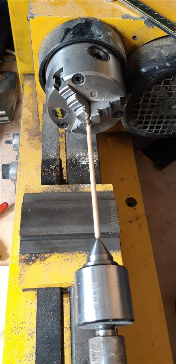
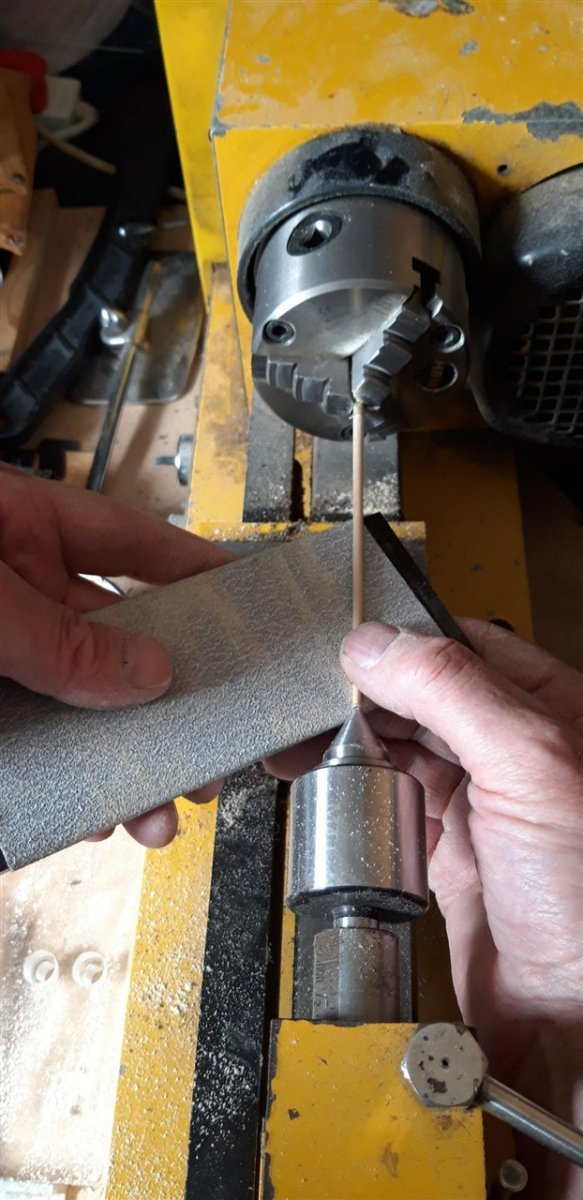
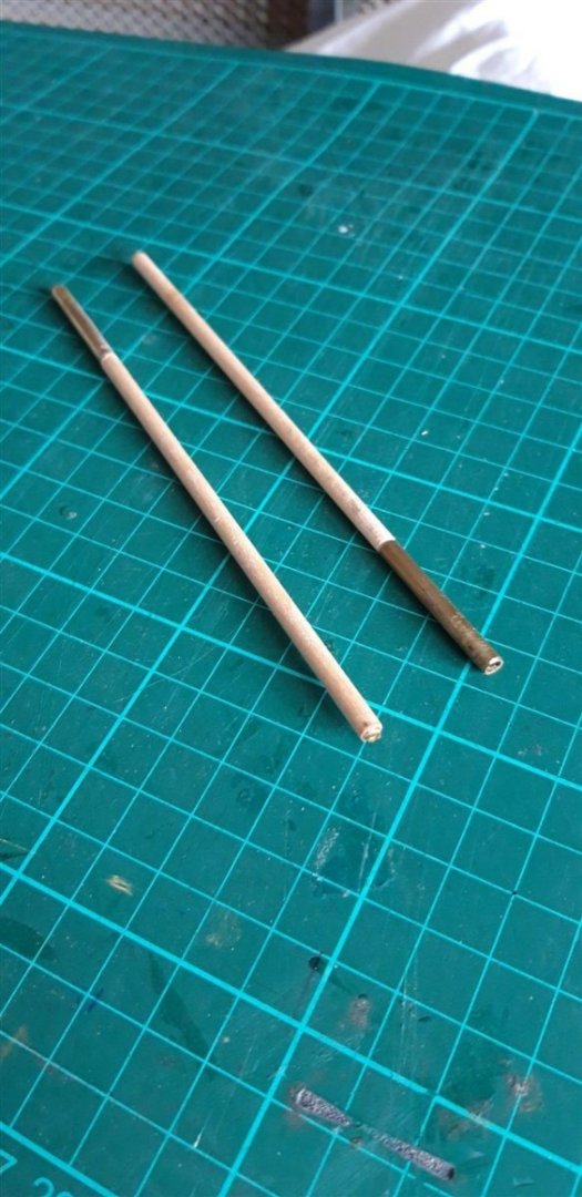
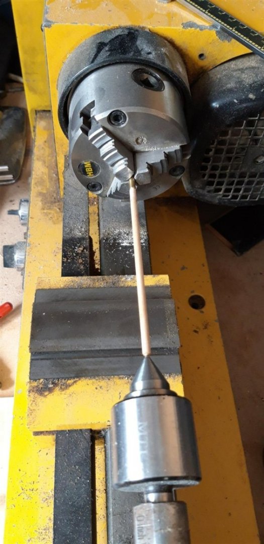
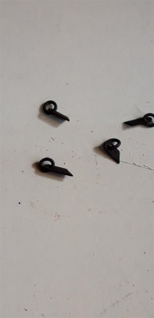
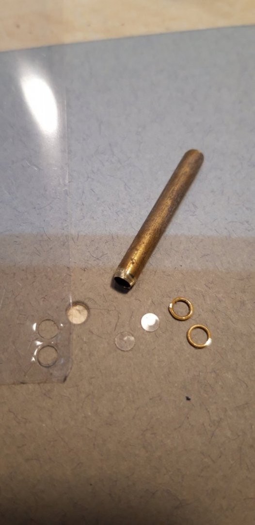
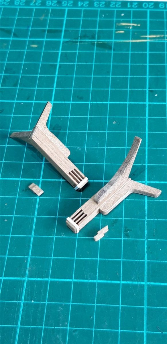
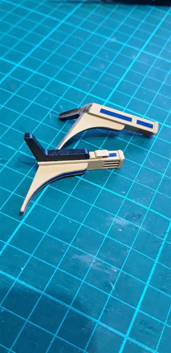
Shaping the knights was very straight forward, as was adding the brass dowels that strengthen them when fitted to the deck. For the boomkins it was time to get on the old Hobbymat lathe. Two over length pieces of 4 mm dowel were first turned down to 3 mm dia. for a short distance at one end to fit snuggly into a short length of 4 mm brass tube. This was to prevent the wood being crushed in the chuck. A 2.5 mm brass ring, clipped off some eyebolts, was glued to the 'narrow' end to help stop the wood splitting when supported by a revolving centre in the tailstock and to give a reference to how much the dowel needed to be reduced. Mounted in the lathe, with the cross slide removed....... the taper was achieved using abrasive paper over a piece of scrap acrylic......... ...carefully using a thumb as a travelling steady. With the Knightheads temporarily located it was a straight forward job to line up the boomkins to mark the angle that they needed to be trimmed to. Once cut. re-enforced with a brass dowel and sanded they were glued to the outer knighthead surfaces. When the glue had set the assemblies were removed and painted. One final fitting, together with the blacked handrails, and then all these components will be put into safe storage until later. Catsheads next - but looking at that last picture I think it's time for a bit of 'housekeeping' on the work bench first ...... Cheers, Graham.


-
Stunning attention to detail, as ever, Robert! Brilliant....
- 527 replies
-
- 1
-
-
- caldercraft
- victory
- (and 1 more)
-
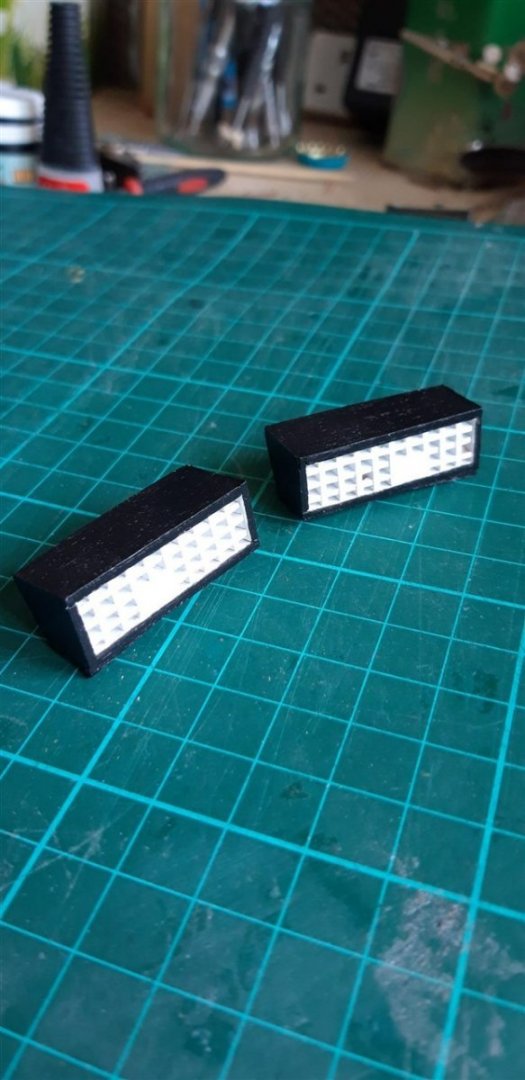
Hi, Thank you for your generous comments. Whenever brass needs blacking I always use 'Birchwood Casey Brass Black'. Once you crack the way to prep the brass first it's pretty straight forward. It works best on brass, however although I've also managed to get good results in copper too.(the copper content is what the chemicals reacted with I believe). The carrinades supplied with the kit differ from the other guns. While the latter are brass and the solution will do the trick, the two Carronades are white metal castings. They were therefore painted. I used Jotika's acrylic 'Matt (metal) Black' They produce the Caldercraft kit. Hope this answers your question. Cheers, Graham.
-
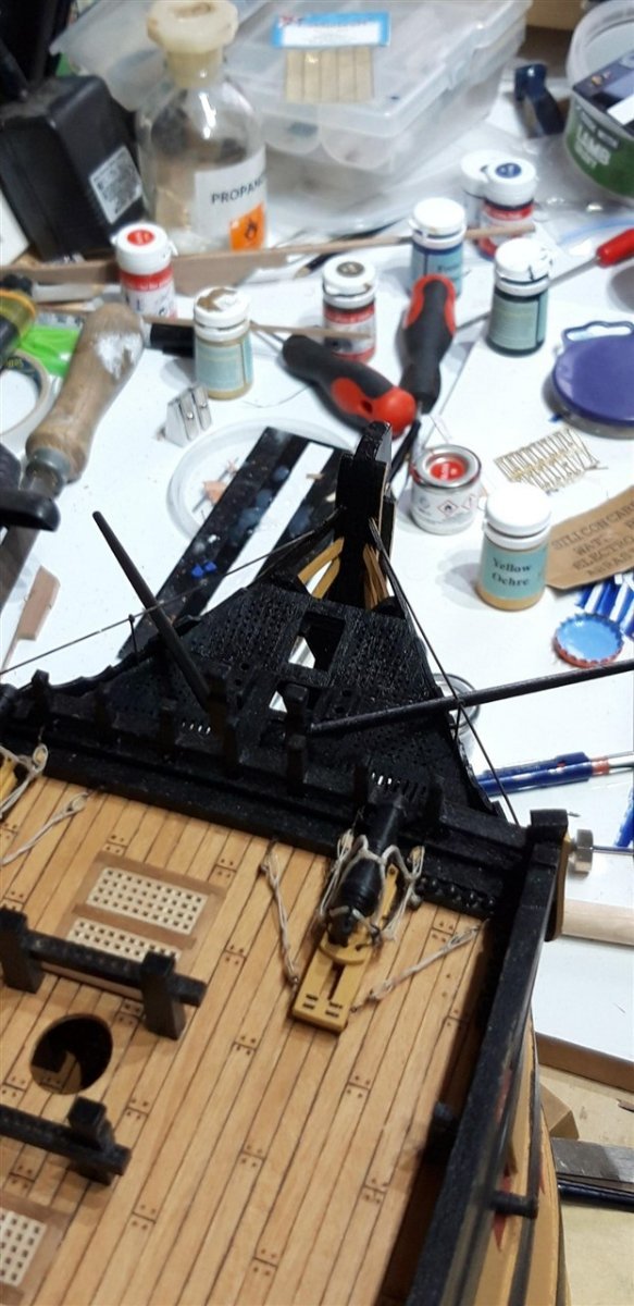
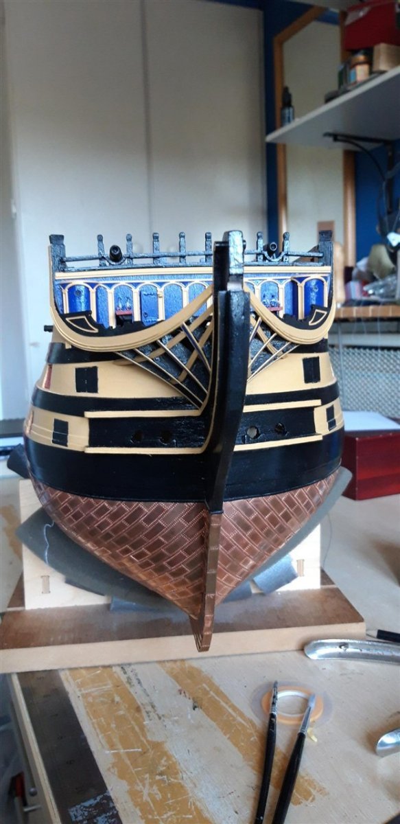
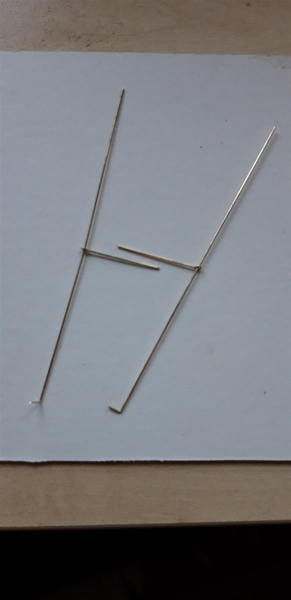
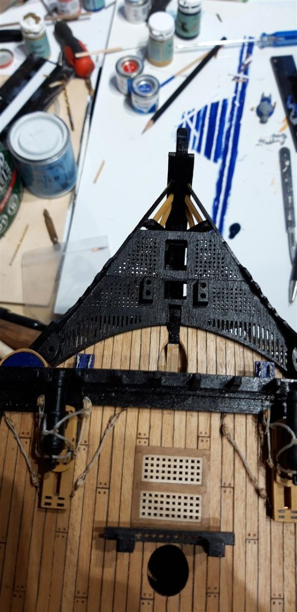
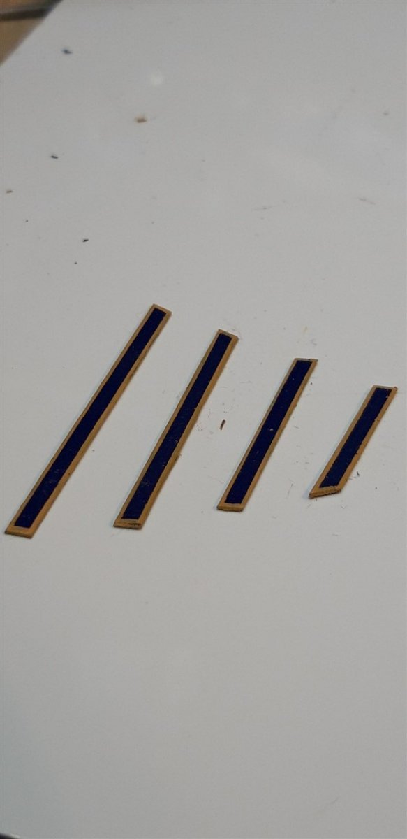
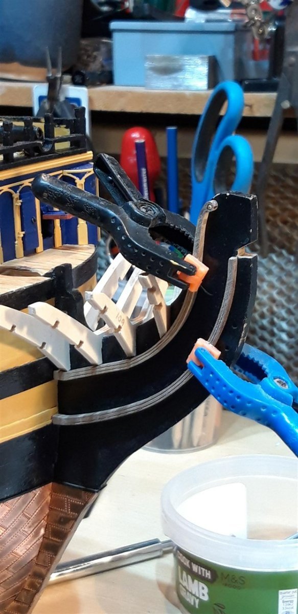
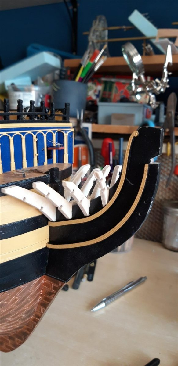
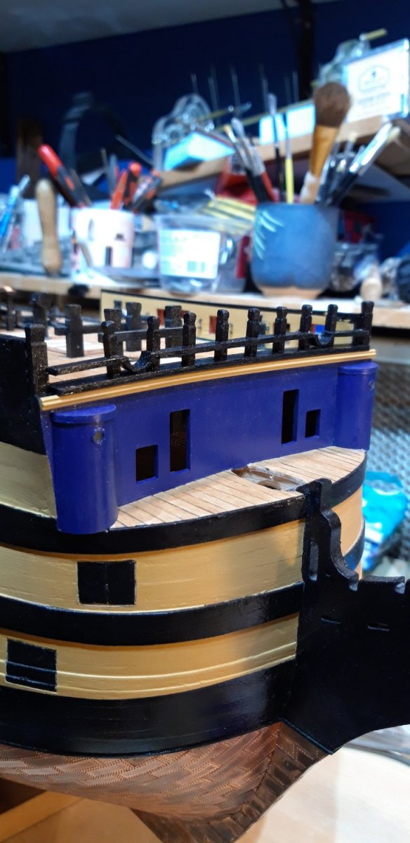
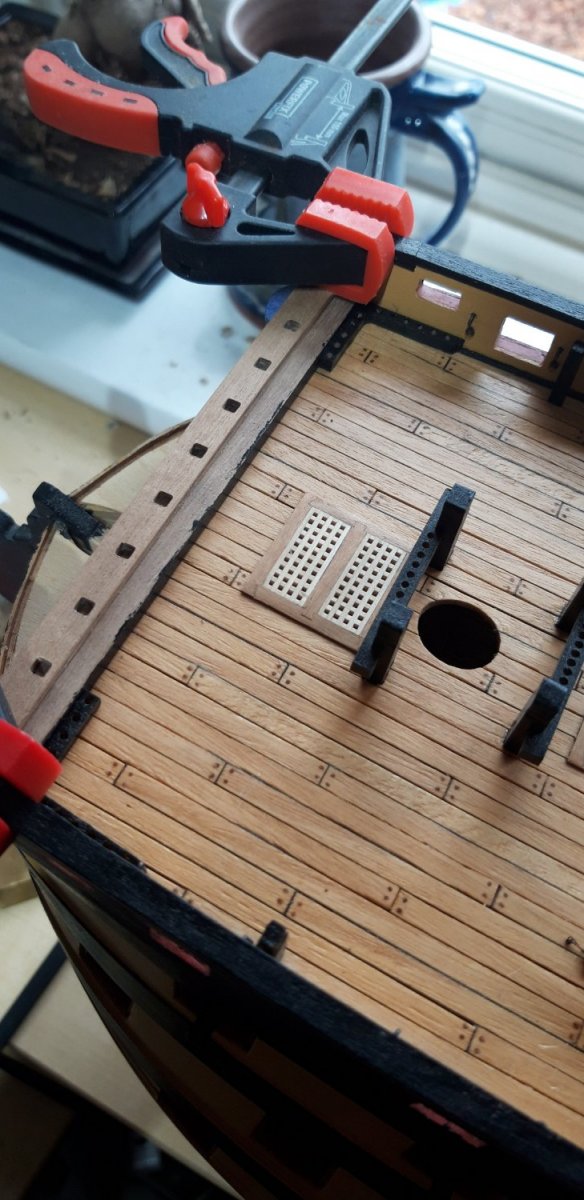
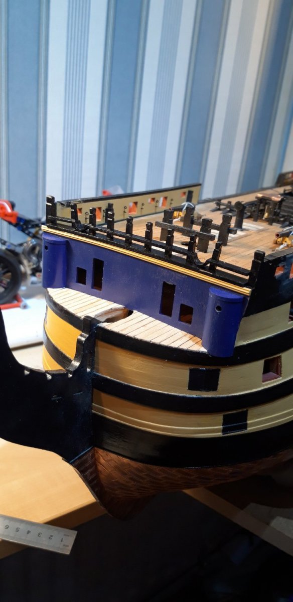
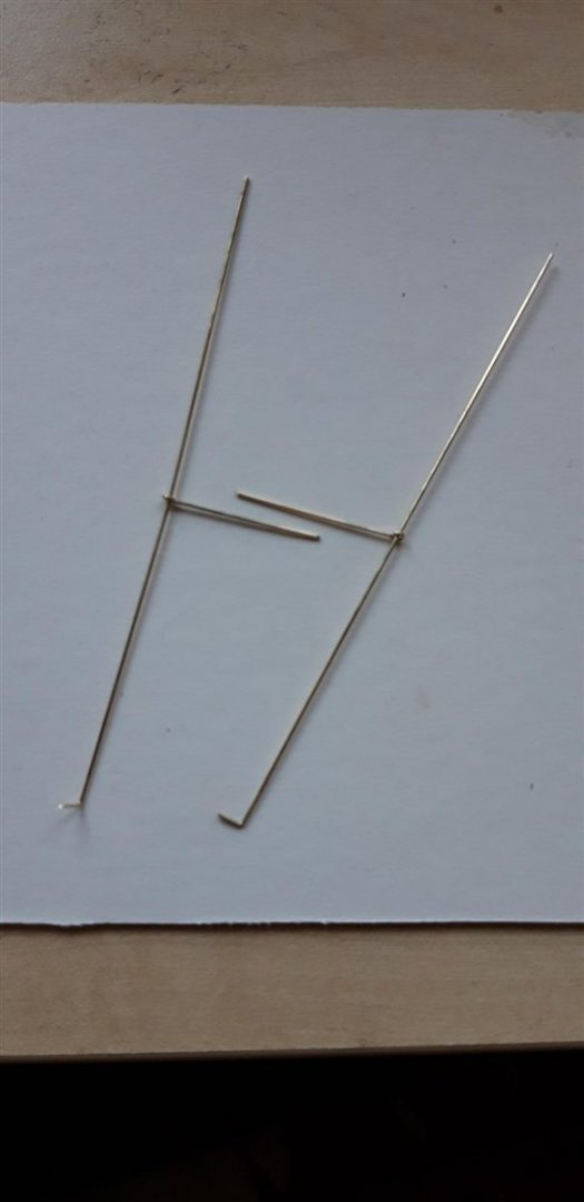
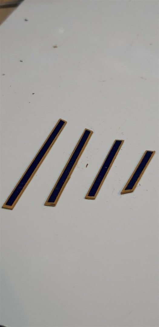
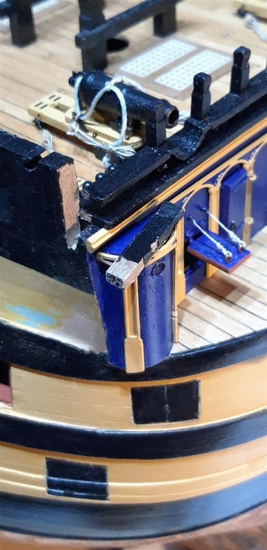
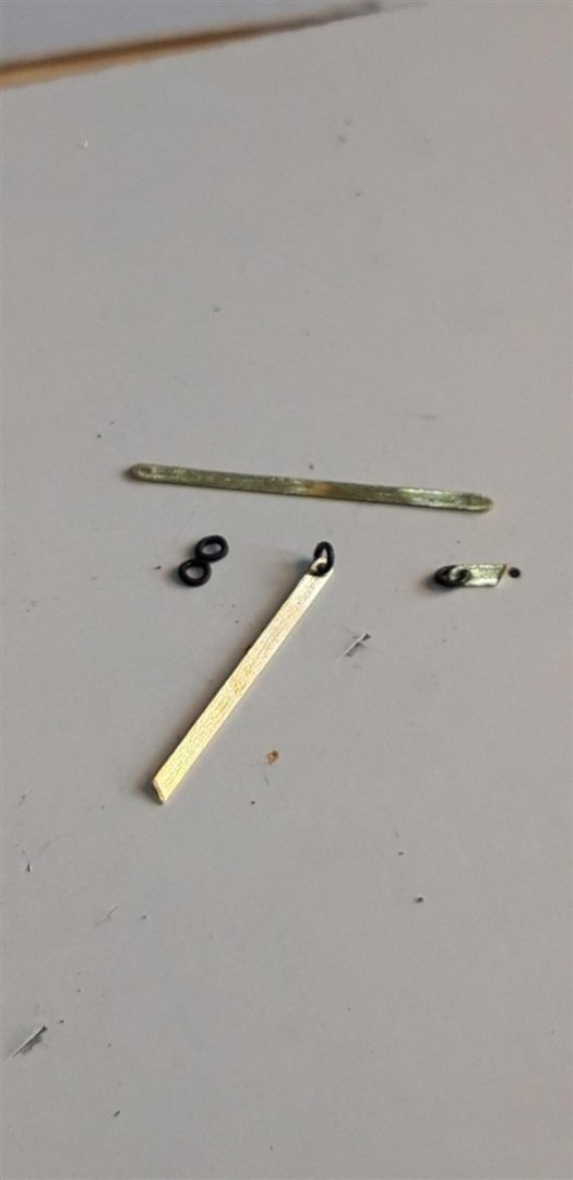
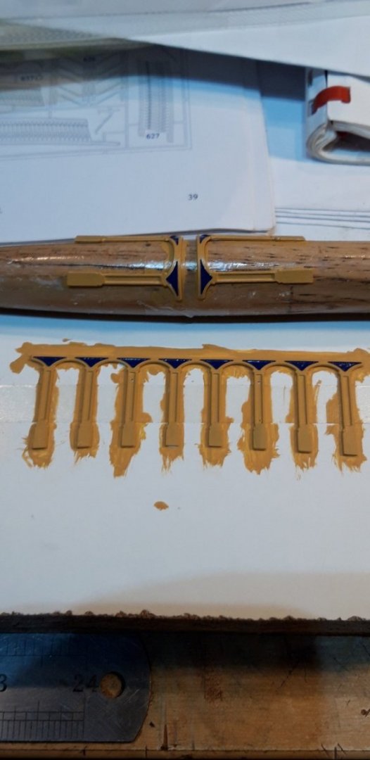
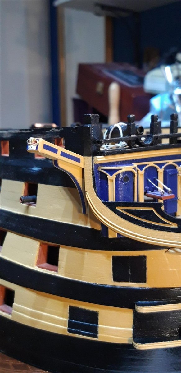
Thanks Robert - much appreciated.... It's been quite a journey but the main bow structure is now complete. Rather than paint the ply sides of the timber heads yellow and then glue a 2 mm strip painted blue on top, I elected to make these decorative strips 3 mm wide, paint them blue and then use 2 mm masking tape up the centre. The unmasked edge areas were then painted yellow. Once a bit of stock strip had been prepared it was cut to size, the ends were painted, and the frame effect was complete. This flatter decoration method seems to match the real thing a little better. Temporarily fitting the two gratings was a great help in working out how the timber heads needed bevelling. The instructions say to line the aft edge of the gratings with 2 mm sq. flexible beech. There was no mention of the need to taper these to match the curve of the deck so I made the decision to go ahead and do this.... Next stage is to produce the stanchions and hand rails from 0.7 mm brass wire. No drawings provided in the plans so it was necessary to glean the shape from on-line photographs. Once dry fitted and then 'blacked' these will be stored safely until later to prevent damage while other tasks are carried out. Knightheads and Boomkins await...... Cheers, Graham.


-
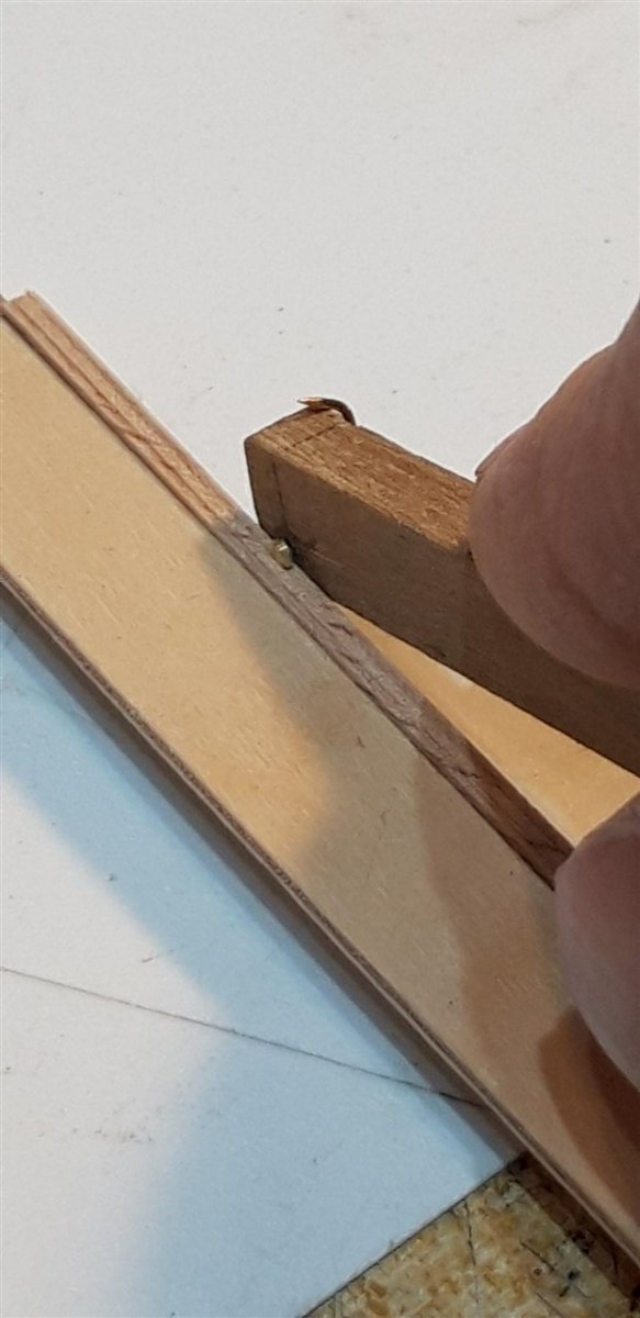
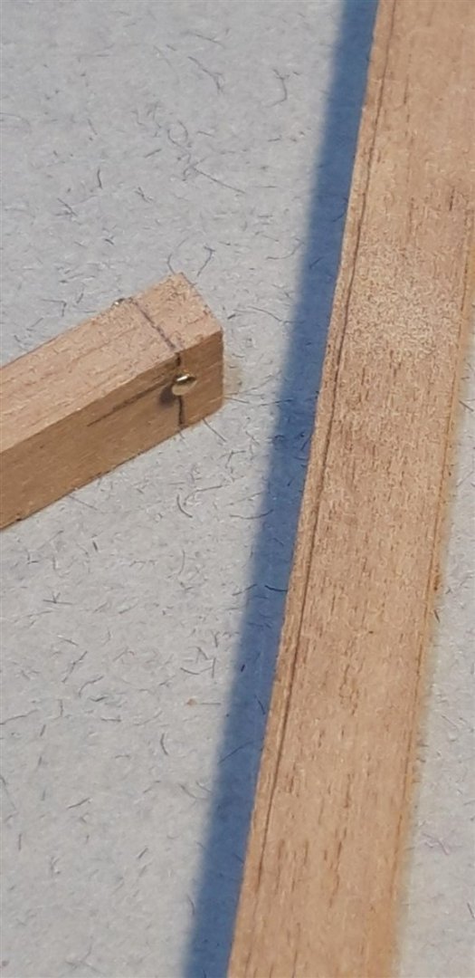
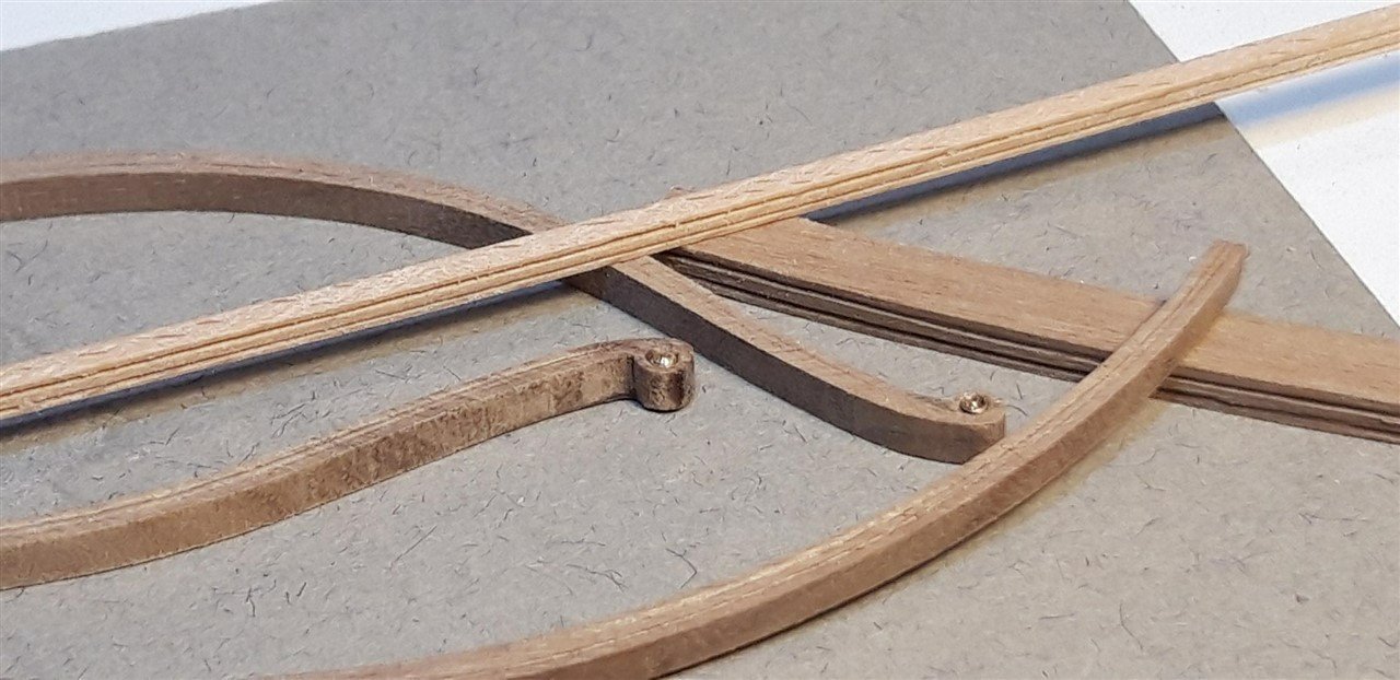
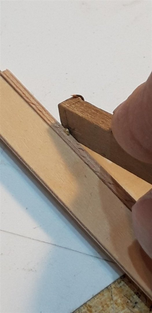
Thanks for the 'likes'! Hope you find the find the planking cradle works for you, Gray - it was my solution to trying to make driving in the pins when first planking a bit less awkward. A quick up-date - comparing the main bow rails supplied in the kit with the full size example on the original currently undergoing renovation in Portsmouth there appears to be, once again, some finer details omitted. The scale versions have a rebate machined along the lower edge which actually have a moulding in real life. To replicate this I decides to try and add some decorative lines. After playing around with a variety of copper wires stripped out of electrical cables I finally went for some soft solder - easy to shape and fix in place with C A glue. Bare solder in place with masking tape over the black painted sections............ All painted and ready for installation......... Getting there.....slowly..... Cheers, Graham.
-
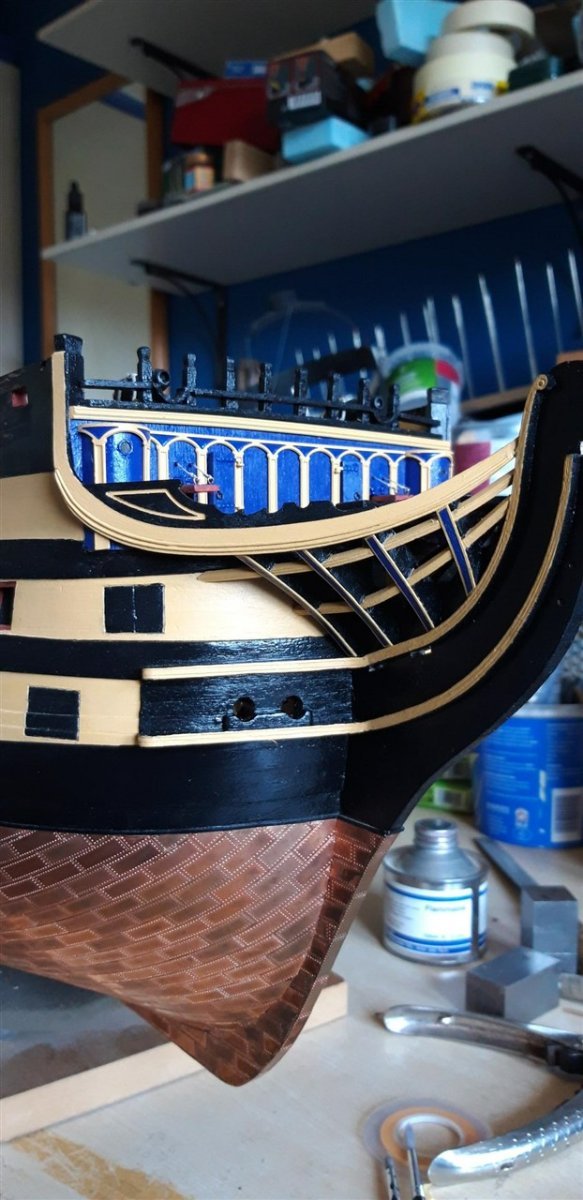
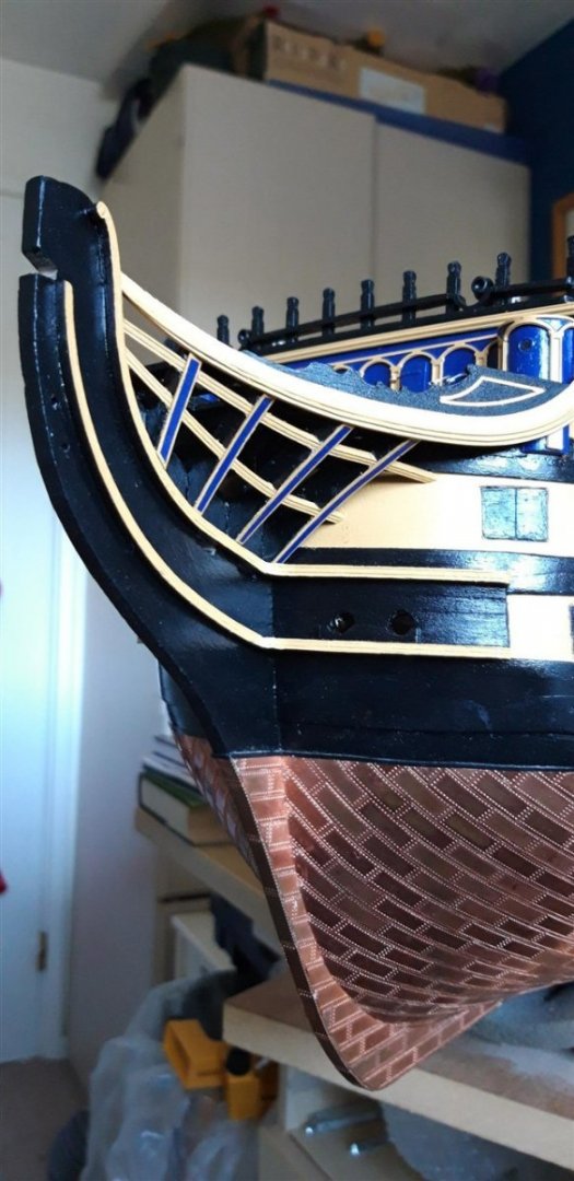
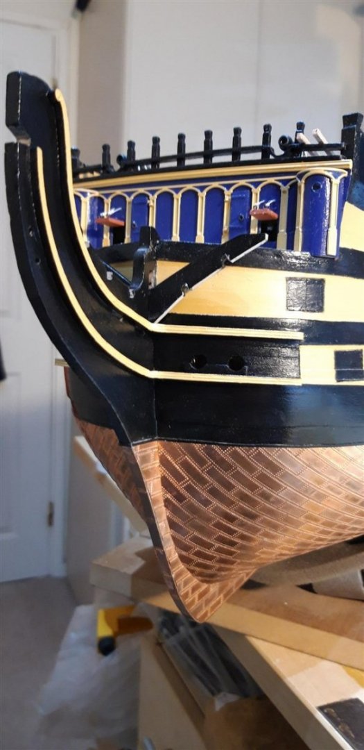
Thank you for your likes and comments - always much appreciated...... Following the manual's instruction to be sure to dry fit the components that make up the bow it quickly became apparent that my modification to the bow main rail inner timberhead was not going to be fit for purpose and would have to go. New replacements were made and fitted at an angle based on Longridge's plan and Robert's excellent work. The end pieces of the fiferail were then re-instated fitting into slots cut in the new posts. These modification were done in tandem with the construction of the hawse area. With the bow curved rails now glued into place the hair brackets and lower bow cheek rails were carefully carved to match the curve of the hull and fitted. Additional 4 x 1 strengthening planks were pre-bent and glued between these, a feature not actually mentioned in the instructions, and then, after much shaping to achieve appropriate inside and outside curves, the hawse hole balisters were added and the hawse holes drilled. These pieces were then painted........ Away from the 'shipyard' for a few days now........ but somehow the figurehead castings have hidden themselves in the luggage together with various paints and brushes.......😏 Cheers, Graham.


-
Photo Orientation
Charter33 replied to stuglo's topic in Using the MSW forum - **NO MODELING CONTENT IN THIS SUB-FORUM**
Hi, I was having the same issue too. It was solved when I downloaded Rob Durant's free picture sizer software. Very helpful video not only explains why the rotation problem occurs, but goes on to clearly explain how to download and then use the program. You can find the link in 'The Captain's Cabin' in the 'How to use the MSW forum'. A very quick and easy fix. Good luck! Graham. -
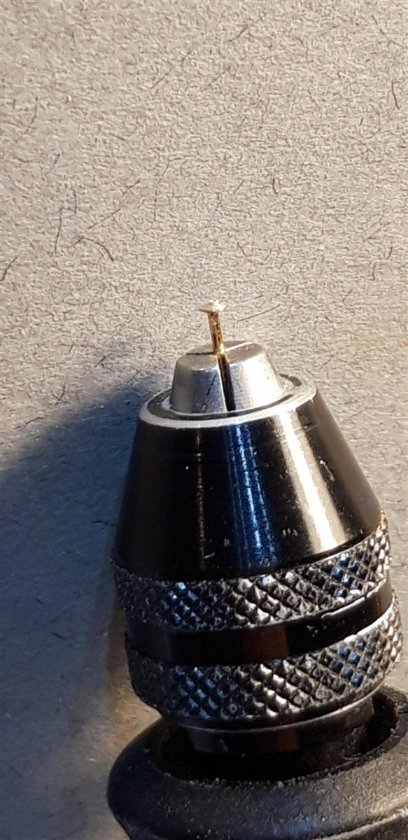
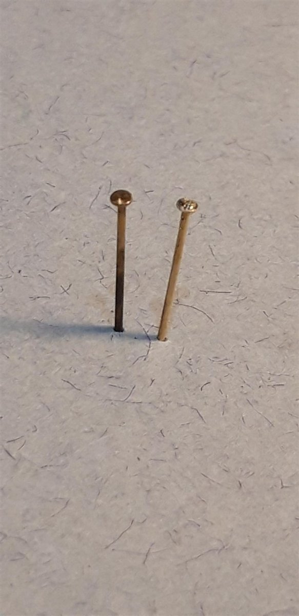
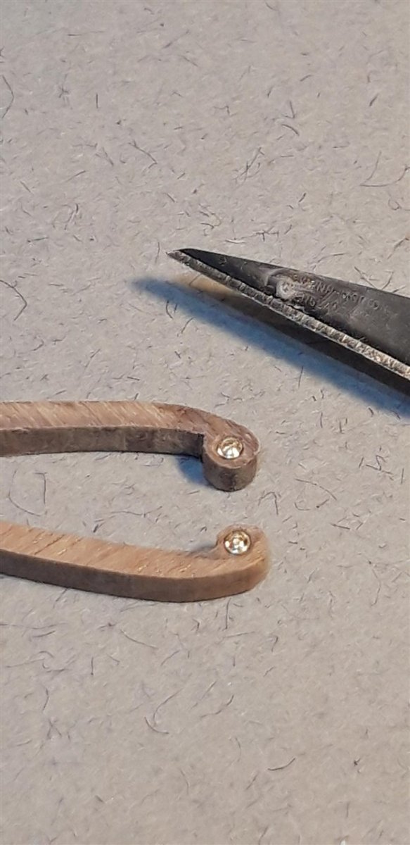
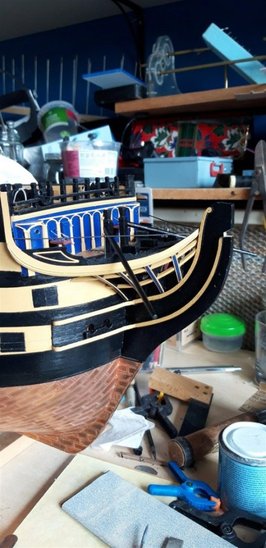
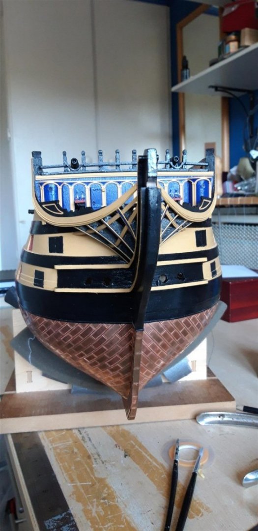
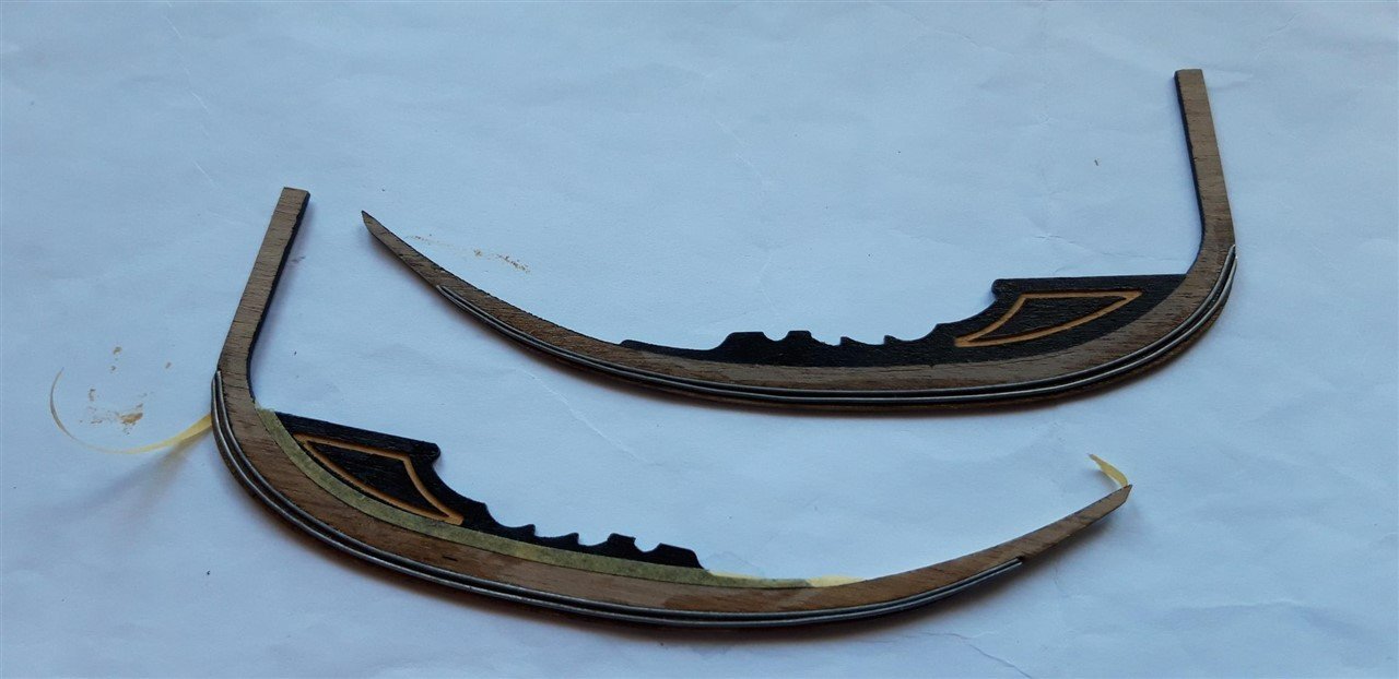
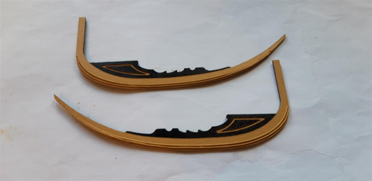
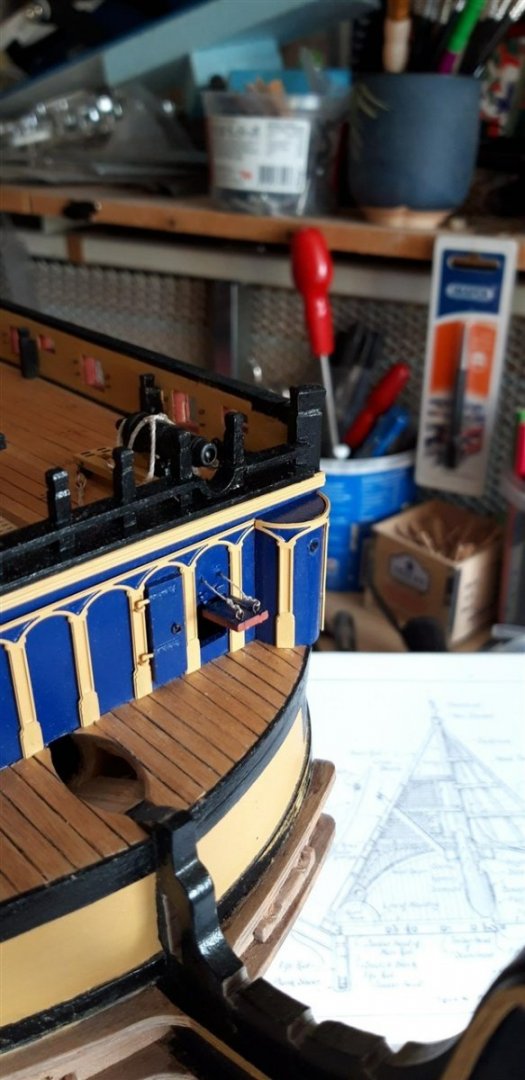
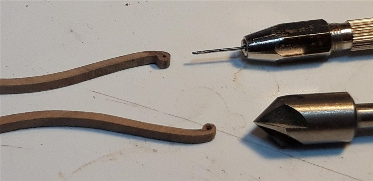
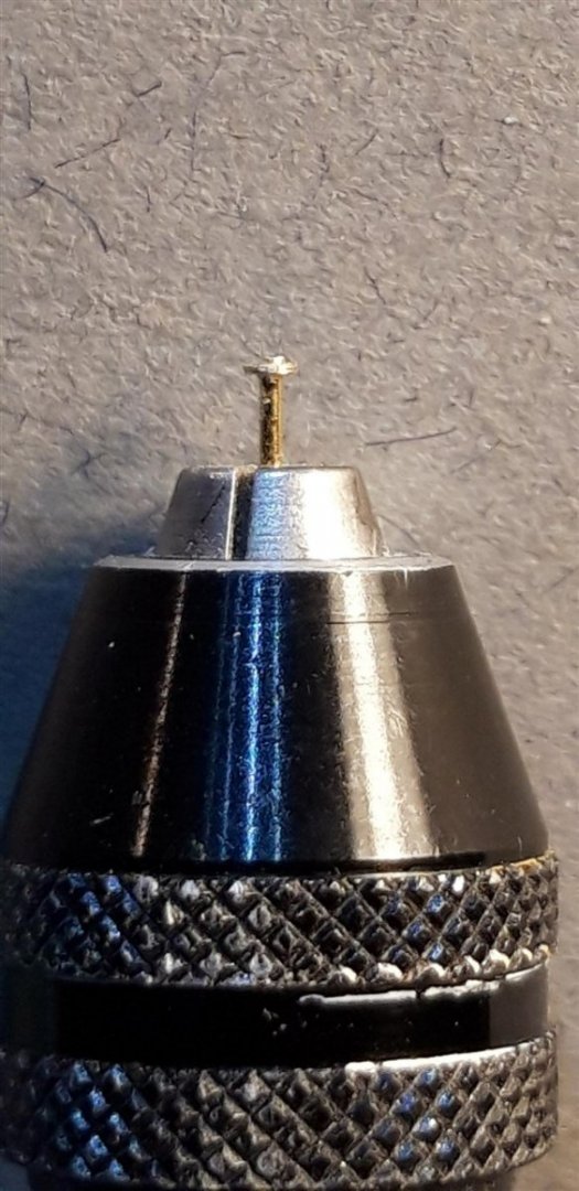
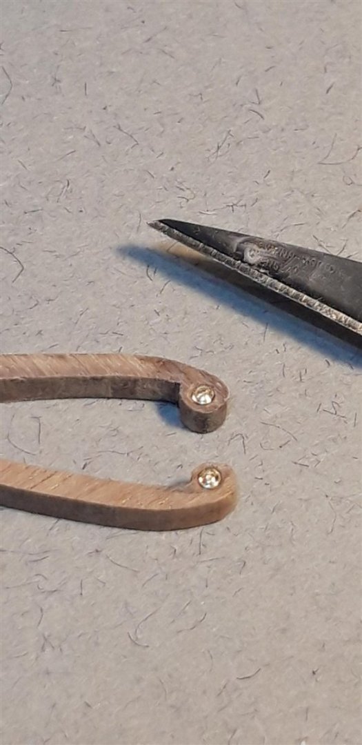
Started the initial stages of the bow - I've been looking forward to this iconic aspect of the ship, and as Robert points out, a truly beautiful area to be working on. There's a lot going on and after reading and re-reading the instructions a couple of times I think I just about understand what's going on 🤔. Researching images of the bows one omission in the kit appears to be the decorative moulding detail on the bow curved rails, the hair brackets and lower bow cheek rails and the rails. I am trying to add the impression of these together with the distinctive scroll at the top of the rear bow curved rails. Scrolls first......... After sharpening up the lower corner where the stem meets the rounded head with a scalpel a 0.75 mm hole was drilled through the scroll's centre. This was the bevelled by hand with a countersink bit. To replicate the scroll's centre I mounted small brass lace making pins in a Dremel and worked the pin head with a combination of needle files and a scalpel blade while rotating it at a slow speed. Cut back to about 3 mm long these were CA glued into place. The next challenge was to work out how to produce the appearance of the mouldings. Producing a micro 'scratch stock' tool was asking a bit too much so I made a tool from scrap walnut and those brass pins that basically rubbed a groove parallel to an edge..... The 2 mm flexible beech needed a simple jig to support it ....... Finished components.... First fitting in conjunction with the timber heads trying to work out the right lines etc. and temporarily again, but now painted. A long way to go, lots of shaping, and many questions still to resolve. I'm guessing that the bow main rails have been made over long and will need trimming to fit behind the bow curved rails, and that the curved rail with the scroll head is mounted very slightly in from the back edge of the stem? Mmm.. think I need to read that 'note' paragraph just above the two pictures on page 30 of the instruction manual again....and again! 🤪 Cheers, Graham.


-
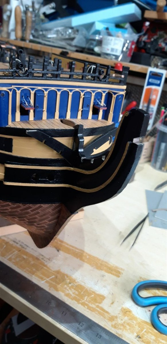
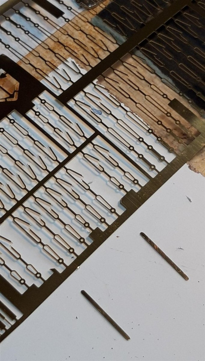
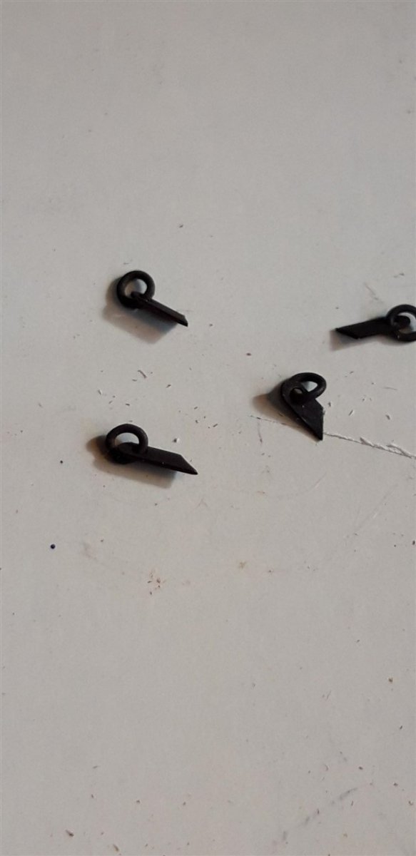
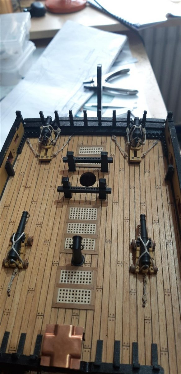
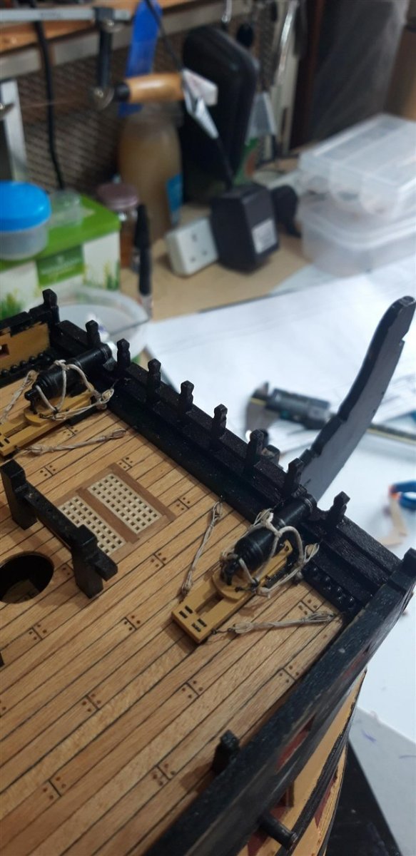
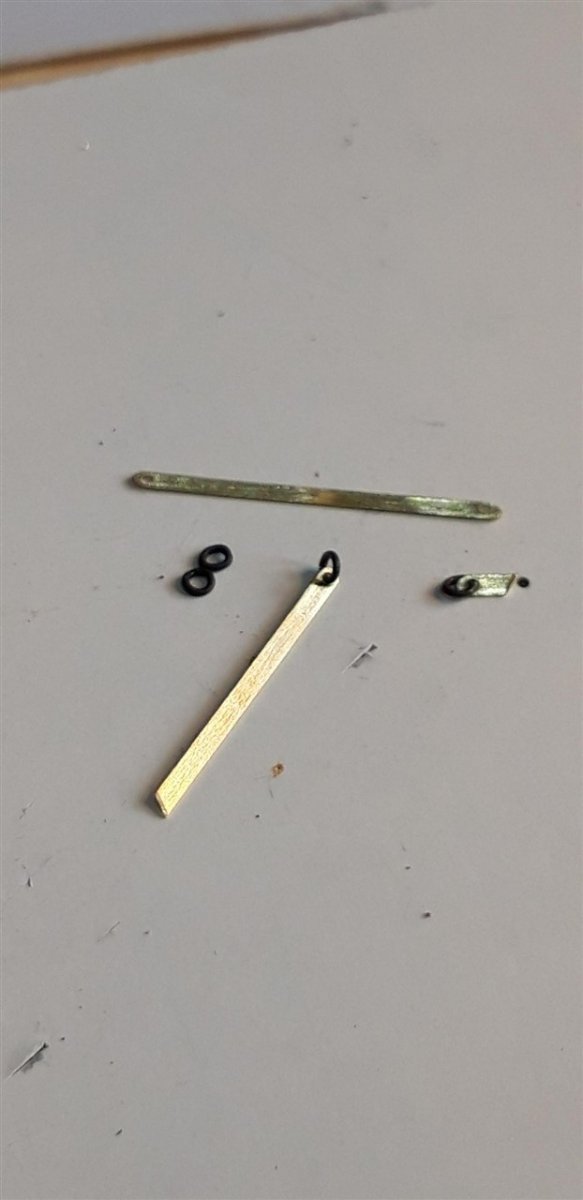
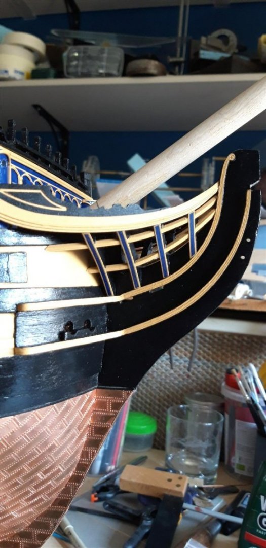
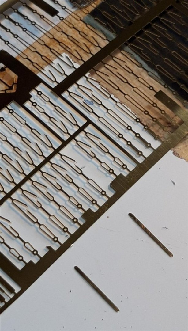
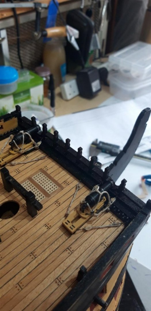
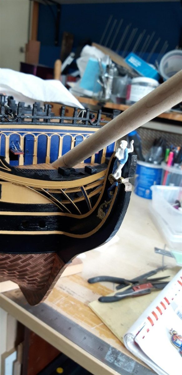
Firstly - a huge thank you to Rob Durant! I was close to abandoning all hope of attaching photographs to my build log, having spent (wasted..) so much time trying to resolve the 'random rotation' of images issue. Rob, your re-sizing app is just what I needed, and your clear and explicit video guide has helped an aging ICT dyslectic 'grumpy old man' regain his sanity..... Cheers!!! The Beakhead now has the gun port lids fitted. I added the tubes for the rigging lines to run through using 0.8 mm dia. black insulation stripped off an internal wire of a redundant phone charger cable. Once broached with a sewing needle the 0.1 dia. rope could just slide through. The prospect of sourcing pairs of tubes for all the other gun port lids this way doesn't bare thinking about so I have followed Robert's advice and purchased thin walled 1.00 mm brass tubing from CMB in readiness for those once the time eventually comes. Construction of the two carronades was pretty straight forward. A couple of points to note - the bottom plate of the carriages needs to be painted black, not yellow as indicated in the instructions. The rings for the breach rope are quite distinctive on the original guns so I replaced the eyelets suggested with my own version. Sourcing brass strip from one of the frames of P.E. components....... ..... ends were radiused prior to drilling, rings fitted, cut to length...... and finally blacked. The ends of the barrels where bored by hand and, while the tools were to hand, I hollowed out the front of the chimney, a task I had forgotten to do. The various tackles etc. took a few attempts get right. Much time viewing images on-line led to in this outcome. Before beginning to work on the bow structure I decided to check the fit of the bowsprite using a short piece of ash that I'd turned to the right diameter, originally to check the alinement of mast holes and mast sleeves. It was a good job I did...... and some attention with carving chisels, scalpel and finally an 11 mm drill wrapped with 320 grit abrasive paper was required. With the fit now sorted it was clear that the transition through the deck was a bit poor with noticeable gaps. This was corrected by replacing the four central planks and re-cutting the elliptical hole. Cheers, Graham.

-
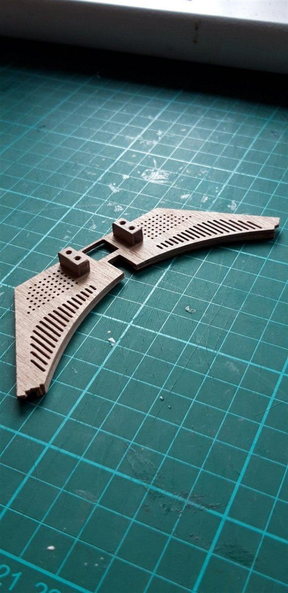
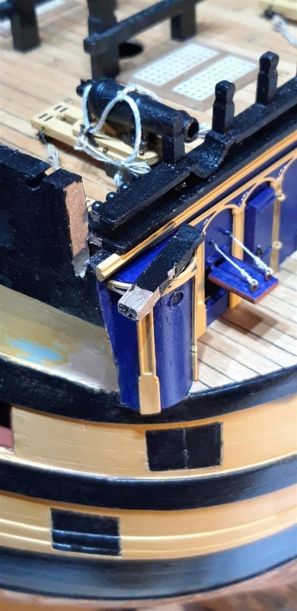
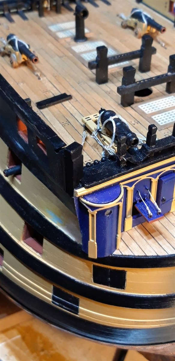
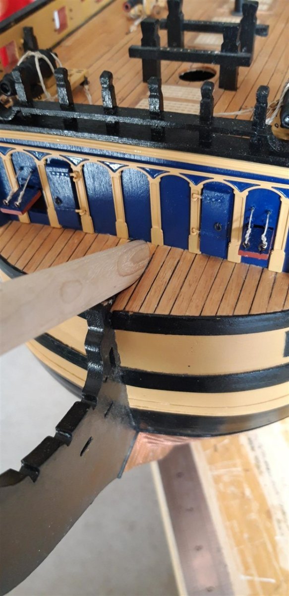
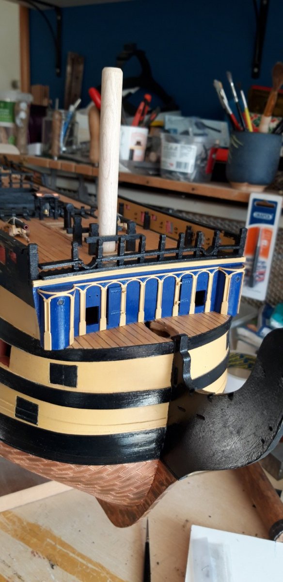
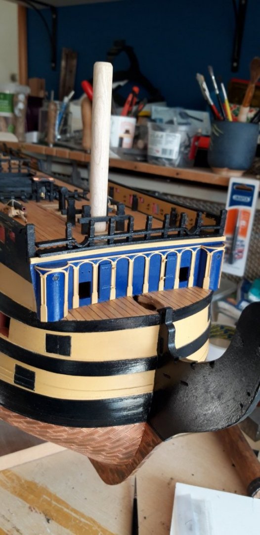
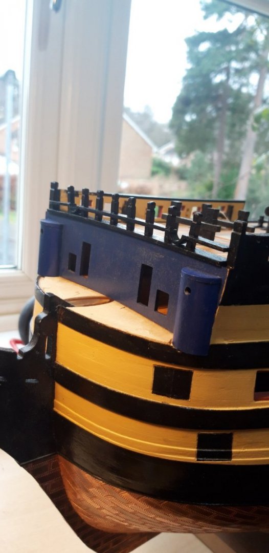
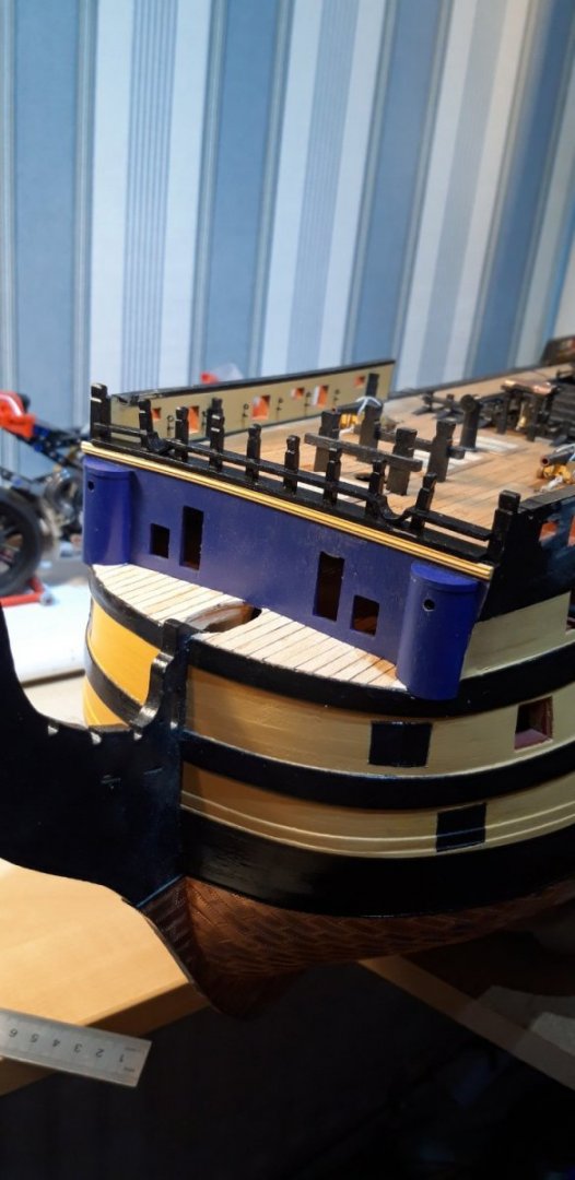
Well..... Just how I managed to get so far with the beakhead without realising that the roundhouse tops needed to be trimmed back to be flush with the walls is a mystery to me.... I could pretend it hadn't happened, but decided to flag it up so that others might avoid doing the same. Suffice to say that that a few minutes work with number 11 scalpel blade and a needle file had the problem sorted and after a remedial paint job - all sorted. The pilasters have now been fitted...... ... doors fitted, and the gun ports prepared and awaiting rigging before they too are added. Cheers, Graham.
-
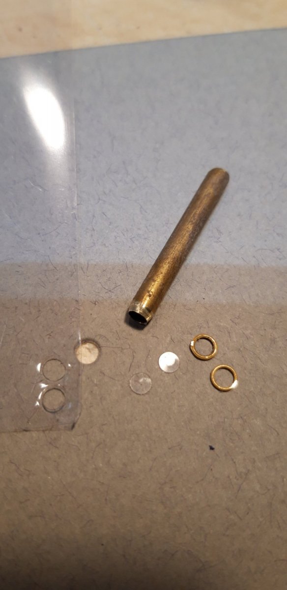
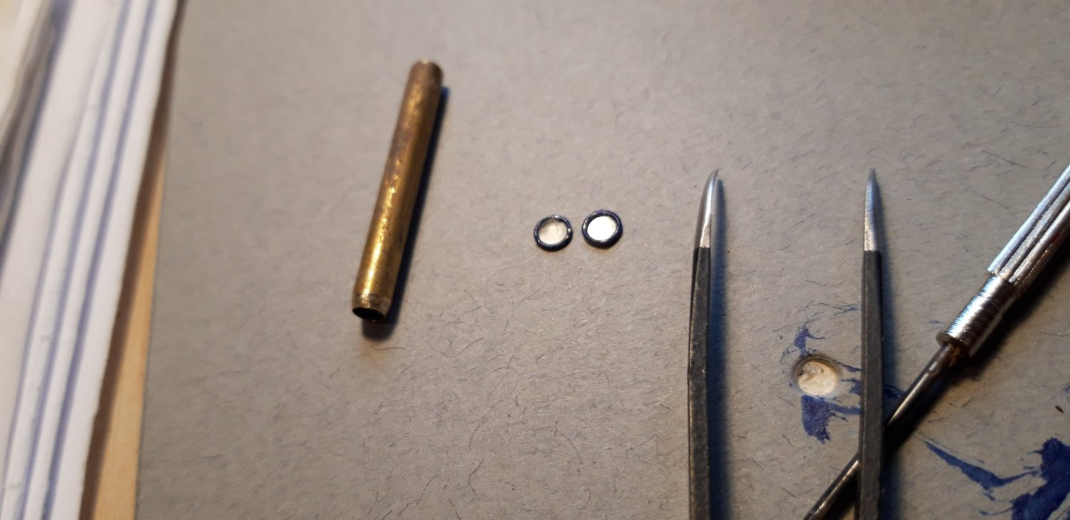
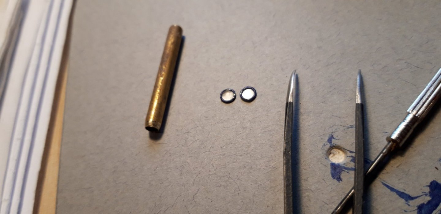
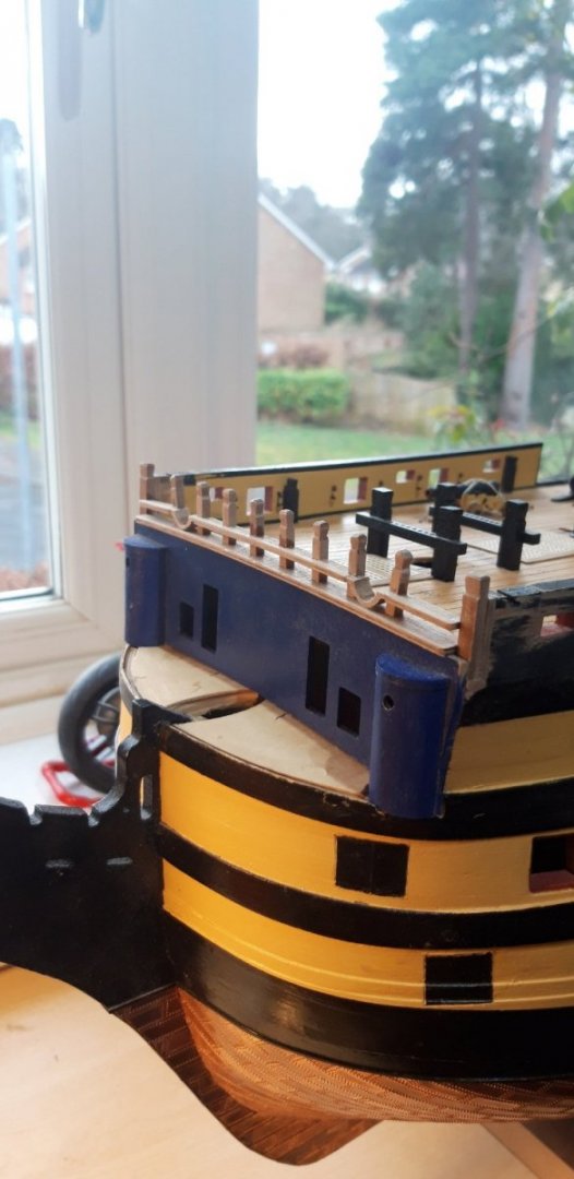
Hi, With the pilasters formed, dry fitted and painted ....... ...... I moved on to the roundhouse windows while the paint dried. I decided to glaze the brass frames. First step was to make a punch to cut the acetate sheet. An off-cut of 4mm brass tube was bevelled to produce a cutting edge. A light tap with a hammer did the job using a piece of card for an anvil. The discs press fitted nicely .... The etched brass frames have a small step on the back so the existing holes I had drilled in each roundhouse were opened out to dia. 3.75mm (no.24 drill). A light application of PVA around the holes and the frames were pressed into place - not quite as easy as that sounds! Then a quick touch up with the blue paint. Cheers, Graham.

-
Hi, Good to hear from you both. Mort - thank you for your welcome back - it really is great to be in a position to once again contribute to this build log, although it did take a little while to get back up to speed! Robert - your build log continues to be my 'go to' thread when things get tricky - such an impressive resource. It seems we share a couple of things other than building the same model purchased from the same retailer (CMB). I've just spotted that you use an identical orange Anglepoise lamp to illuminate your work bench as I do, and I too have also recently been 'elevated' to the illustrious role of a grandparent. Puts a whole new perspective to things.... Progress today..... first step was to add the Cat-tails followed by the Beakhead capping assembly. I had an issue here with the bow main rail inner timberhead pieces. The instructions seemed straight forward, but combined with the plans it appeared a bit ambiguous and vague. Perhaps it's old age creeping up on me but things didn't add up. I have a feeling I may not be the only builder to have been in this position. I ended up falling back on my copy of John McKay's 'The Ships Anatomy' and of even more help, Longridge's 'Anatomy of Nelson's Ships'. The two parts provided in the kit were discarded and replaced with a slightly longer version. The rest of the bulkhead timbers and fiferail assembly went together without any problems. After an initial coat of paint......... the pre-painted length of brass profile was glued beneath the plank sheer, and the front section of the upper gun deck was planked using the black cotton caulking technique used with all previous planking. The photograph shows them prior to cleaning up and matt varnishing. Off to find a jubilee clip and an appropriate socket spanner to shape the roundhouse pilasters (thanks for the tip Robert!) Cheers, Graham.

-
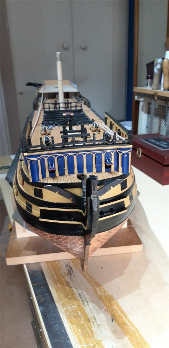
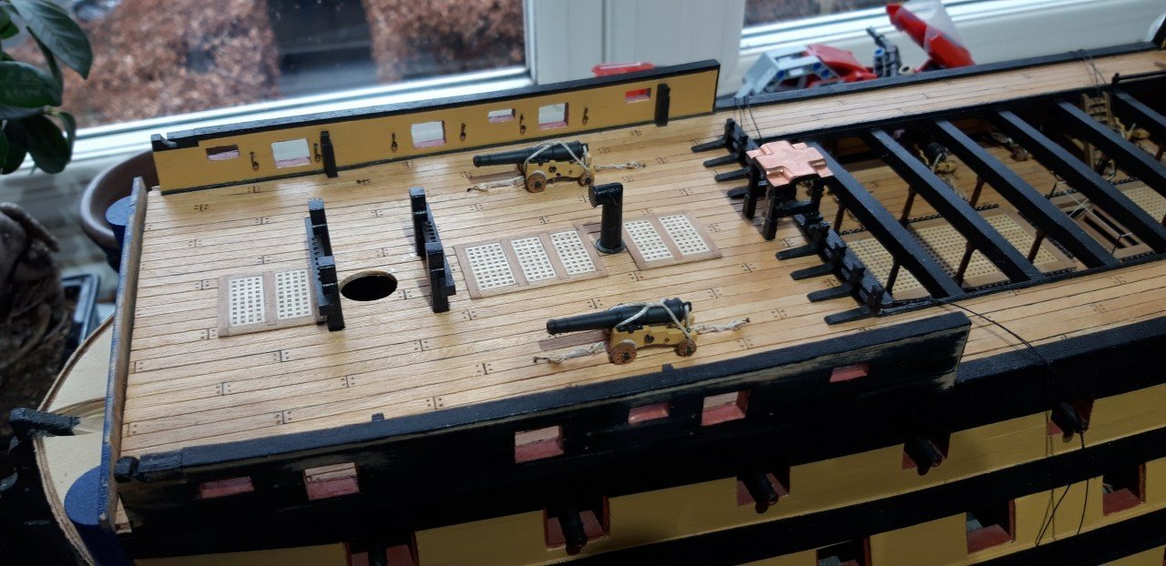
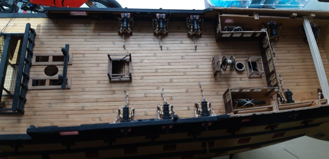
Some progress to share.......and a new laptop to help with the process too...... After removing the dust sheet that has been protecting the hull while in storage (for far too long!) work has continued with fitting out the quarter deck. The Barricade assembly and waist ladders are now in place and the rigging openings have been lined. The main companionway and the one to the Admiral's Dining cabin were straight forward to construct and fit as were the binnacle and ship's wheel. After digging out the various jigs I made to help with the gun carriages and their associated tackles and breaching ropes on the previous deck, and re-reading my build log to remind me how to use them 😕..... the 12 quarter deck cannon and two forecastle guns were assembled and then fitted into place. Good to be back at the work bench. Cheers, Graham.
_1280.jpg.0fd756771a34e7a0ca6688dd990e6f1d.jpg)


_1280.jpg.c5c18d9150c5c60019bb1c098479aa6a.jpg)


.jpg.bb11b51b5aae4cc90d358b26bc46db53.jpg)