No Idea
-
Posts
1,036 -
Joined
-
Last visited
Content Type
Profiles
Forums
Gallery
Events
Everything posted by No Idea
-

Question re "Line Off"
No Idea replied to JohnWW's topic in Building, Framing, Planking and plating a ships hull and deck
Hi John Yea I did exactly that when I made my last model - Its great practice but also time consuming. Its also much easier to line off the second layer as you have the correct rounded shape of the hull without having to deal with bulkheads - good luck Mark -
Question re "Line Off"
No Idea replied to JohnWW's topic in Building, Framing, Planking and plating a ships hull and deck
In that case you can put the first layer of planks on just as the picture above shows. This layer will help you get the shape of the hull probably with a bit of filler too. You will only need to line off your second layer of planking as this will obviously be seen. -
Sherline Mill Ring Light
No Idea replied to No Idea's topic in Modeling tools and Workshop Equipment
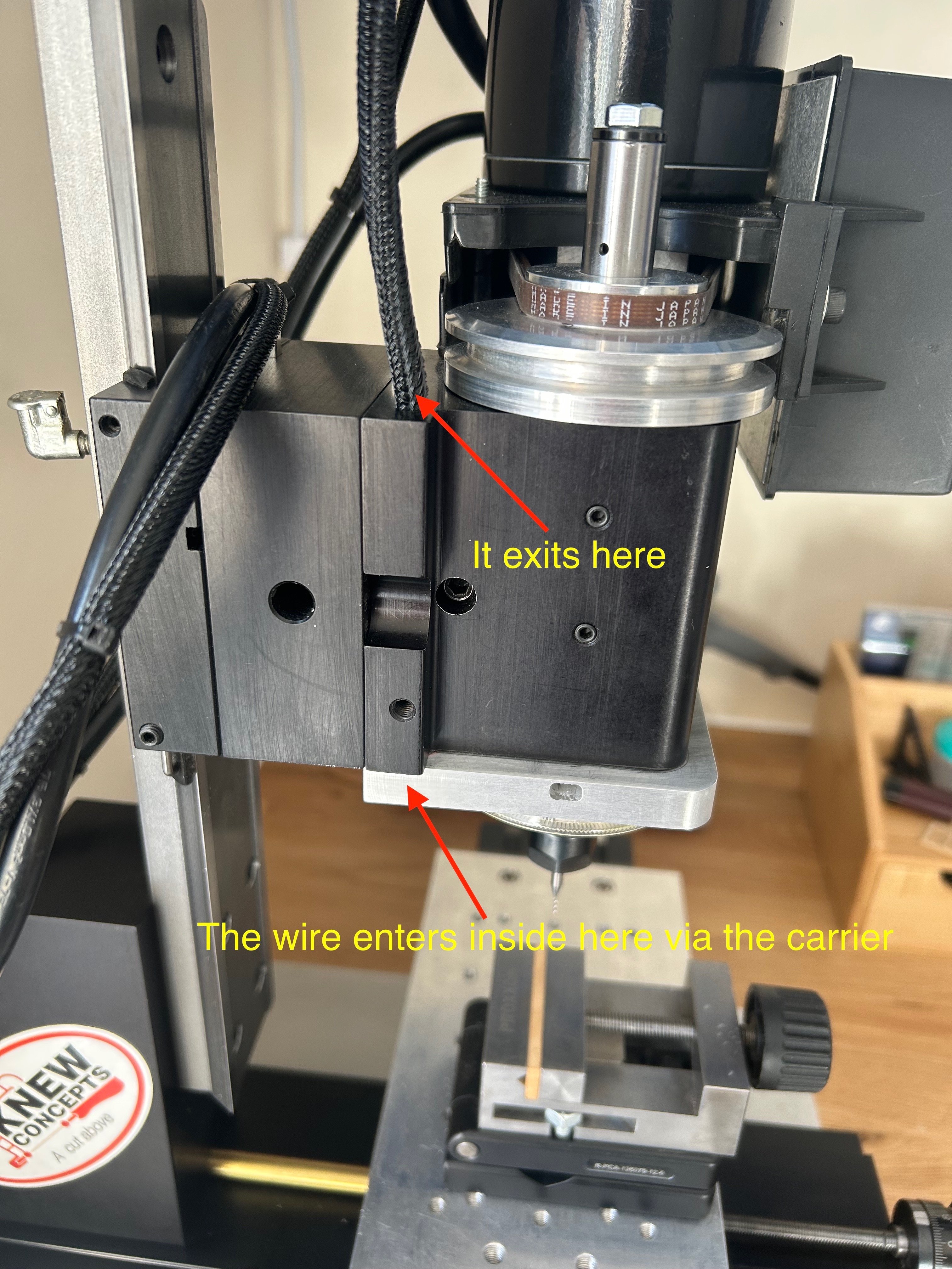
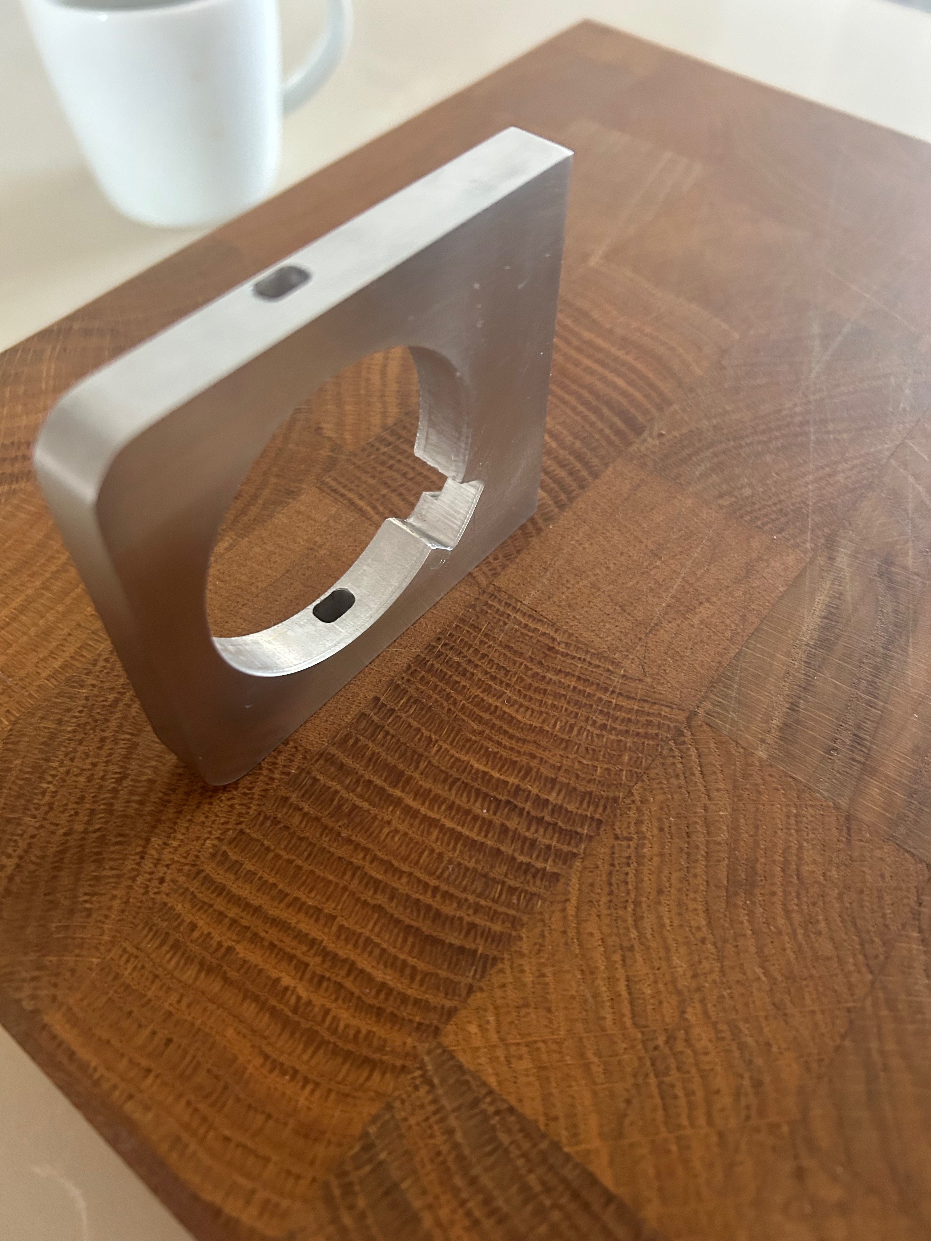
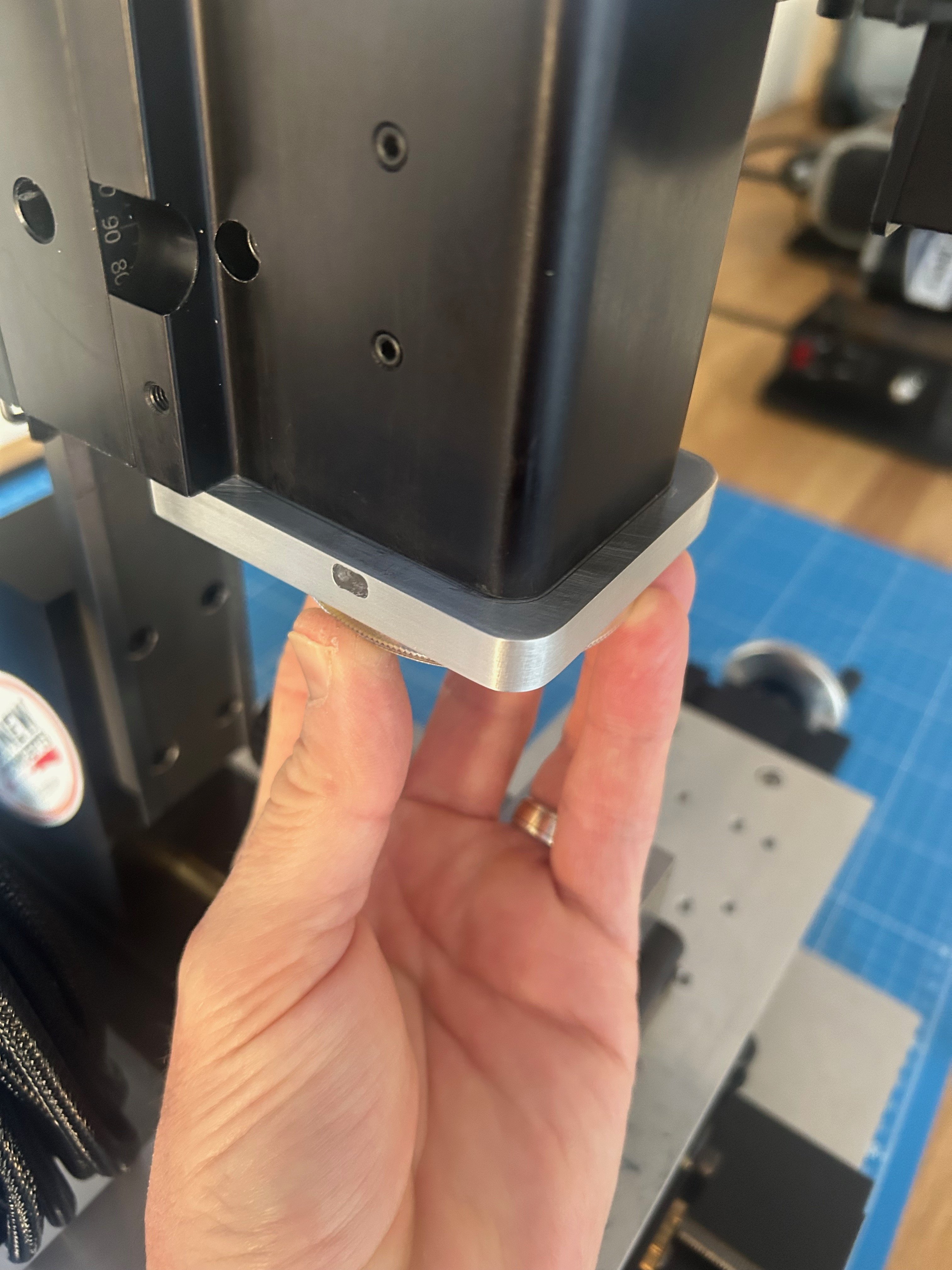
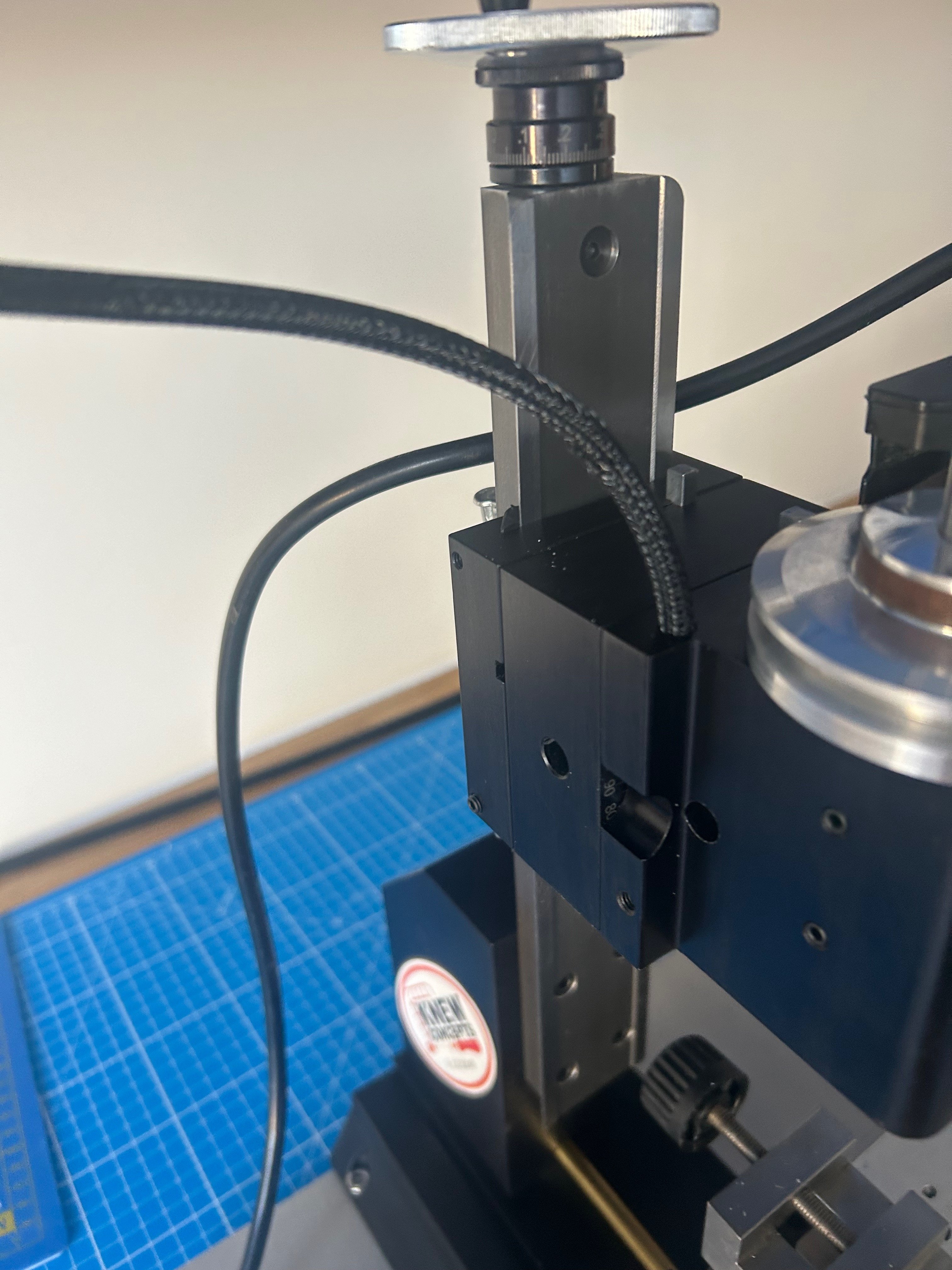
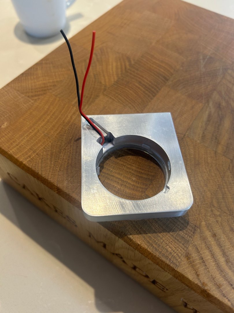
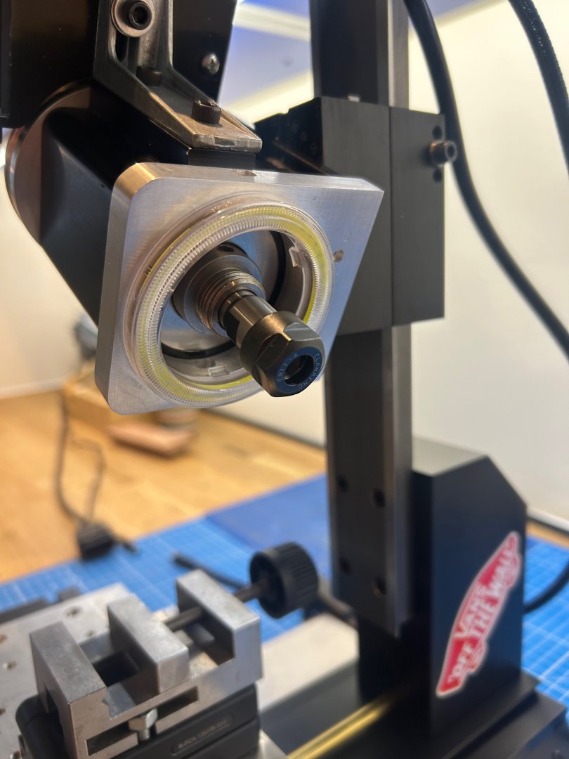
Hi Ian - Thats a really good question and one that I had thought about too. I was going to use a fly cutter which is perfectly feasible but as I machine in my home I didn't want too much swarf. I cut the hole by using a rotary table with a 4 jaw chuck so the centre came out in one piece. I used a 3mm 2 flute end mill to do this. The wires run directly through the mill head - here's a better picture @Dr PR many thanks for the explanation that makes sense to me now 👍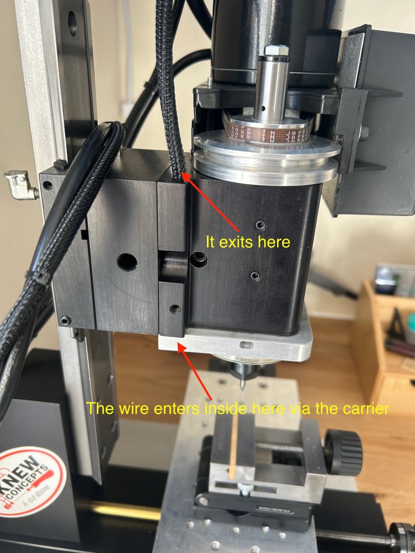
-
Question re "Line Off"
No Idea replied to JohnWW's topic in Building, Framing, Planking and plating a ships hull and deck
Hi John is your model double planked or single planked? Also is the hull going to be painted? -
Sherline Mill Ring Light
No Idea replied to No Idea's topic in Modeling tools and Workshop Equipment
Hi Paul - you know what a yellow filter may just calm down the stark colour of white so thanks for that as it's something I may try. As for pulse width modulation - mate is this a name of a new band? Only joking - I'm a bit old now and I don't understand electrics at all. In fact my wiring is probably questionable at best but I do think that people that understand this aspect could easily move this forward as you suggest. In fact if they do let me know in very very simple terms how to do this. I just run the light off of a 12v plug in charging transformer. -
Question re "Line Off"
No Idea replied to JohnWW's topic in Building, Framing, Planking and plating a ships hull and deck
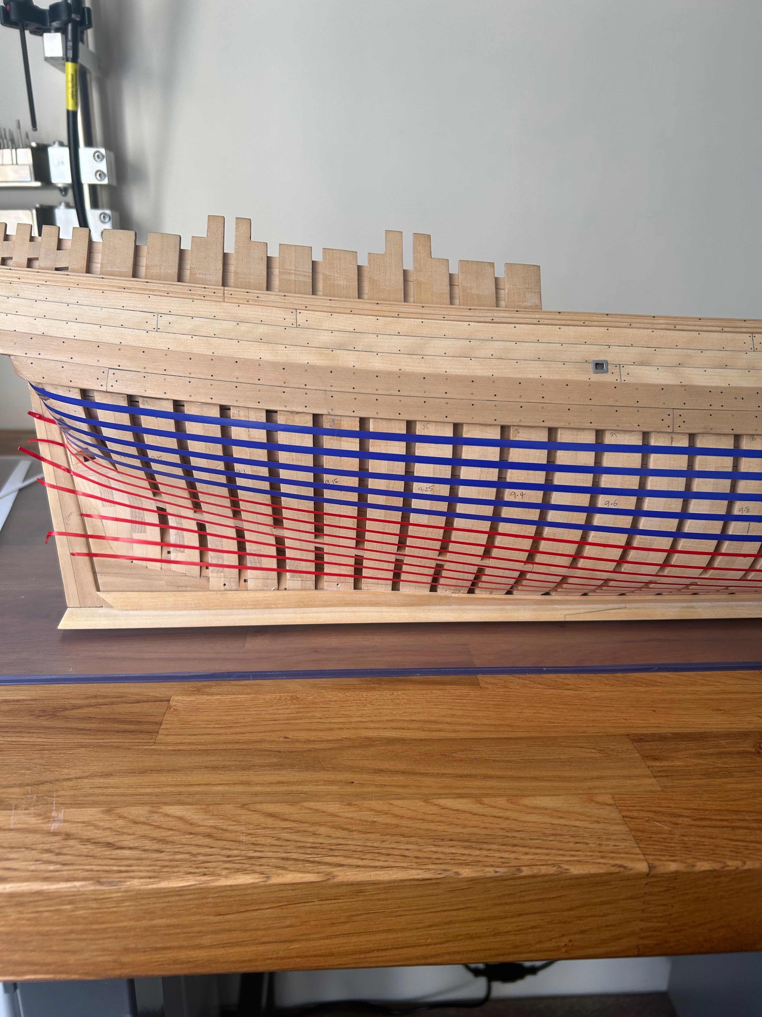
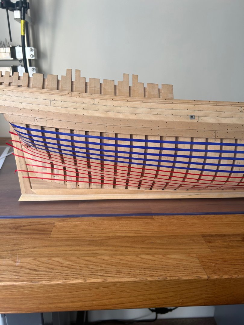
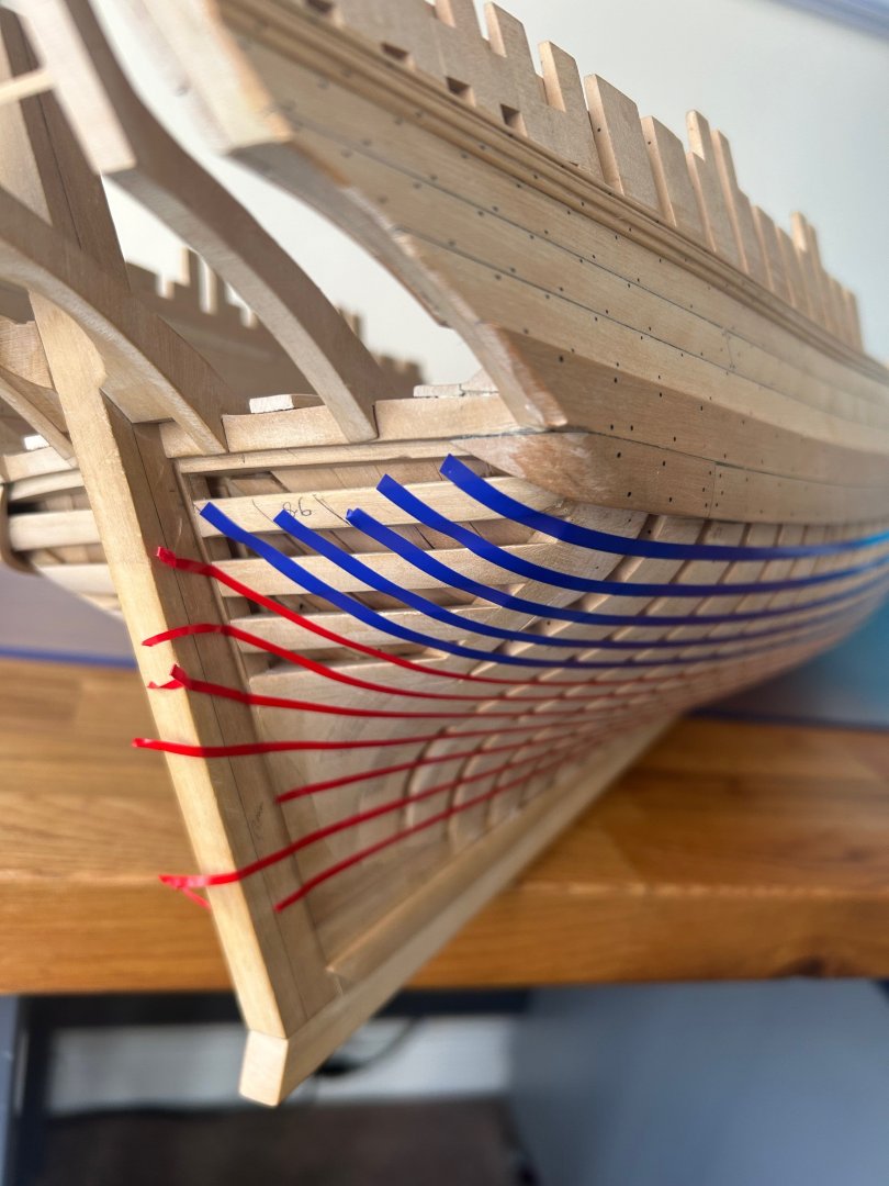
Hi JohnWW this is what lining off looks like It's about the planning of the planking strakes (runs) so that you know how every single plank will fit. It will give you the dimensions of each strake too. Some more pictures to help you You can use tape, string, cotton or anything that will follow the lines. Now this may seem like an awful lot of planning and yes it takes a lot of time to get this right - however - if you can draw the strakes you can make them! If you line off your hull it takes all of the guess work out of planking and you have pretty much won the battle before even cutting your first piece of wood. Read the tutorials on here as they will help you through the process. Good luck! Mark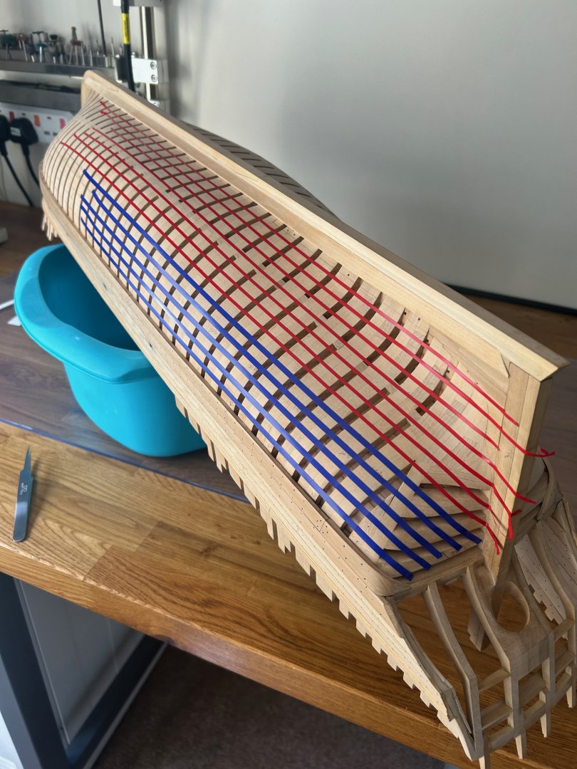
-
Sherline Mill Ring Light
No Idea replied to No Idea's topic in Modeling tools and Workshop Equipment
Hi Mark - yep you are spot on they are sold as car accessories. I got two of these lights for £10 delivered You are right about the cold white light. It would also be good if they could be dimmed a little too. -
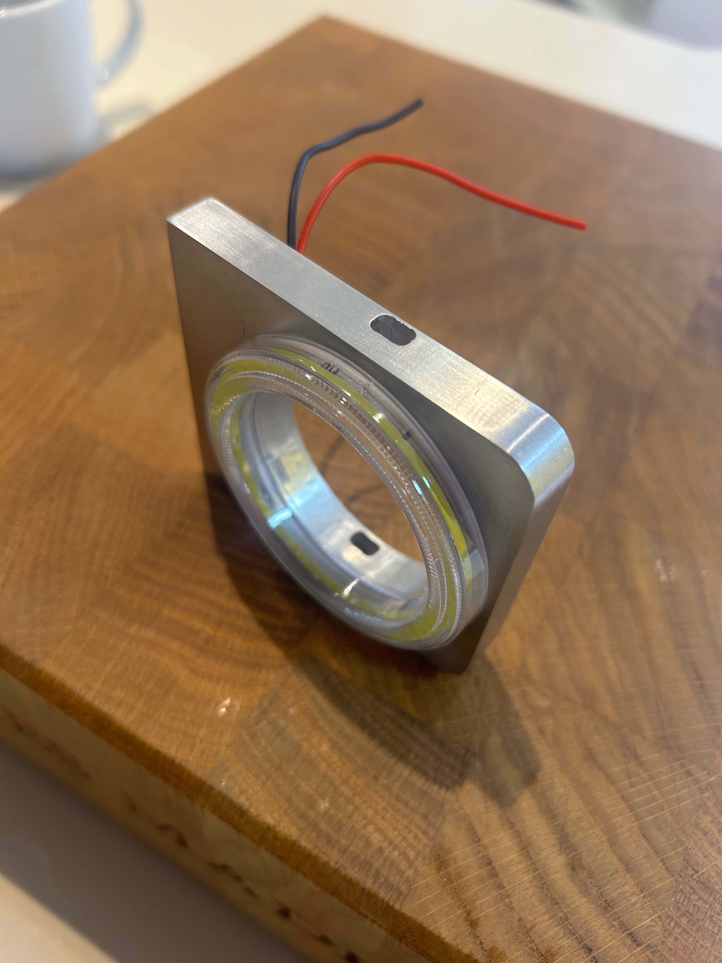
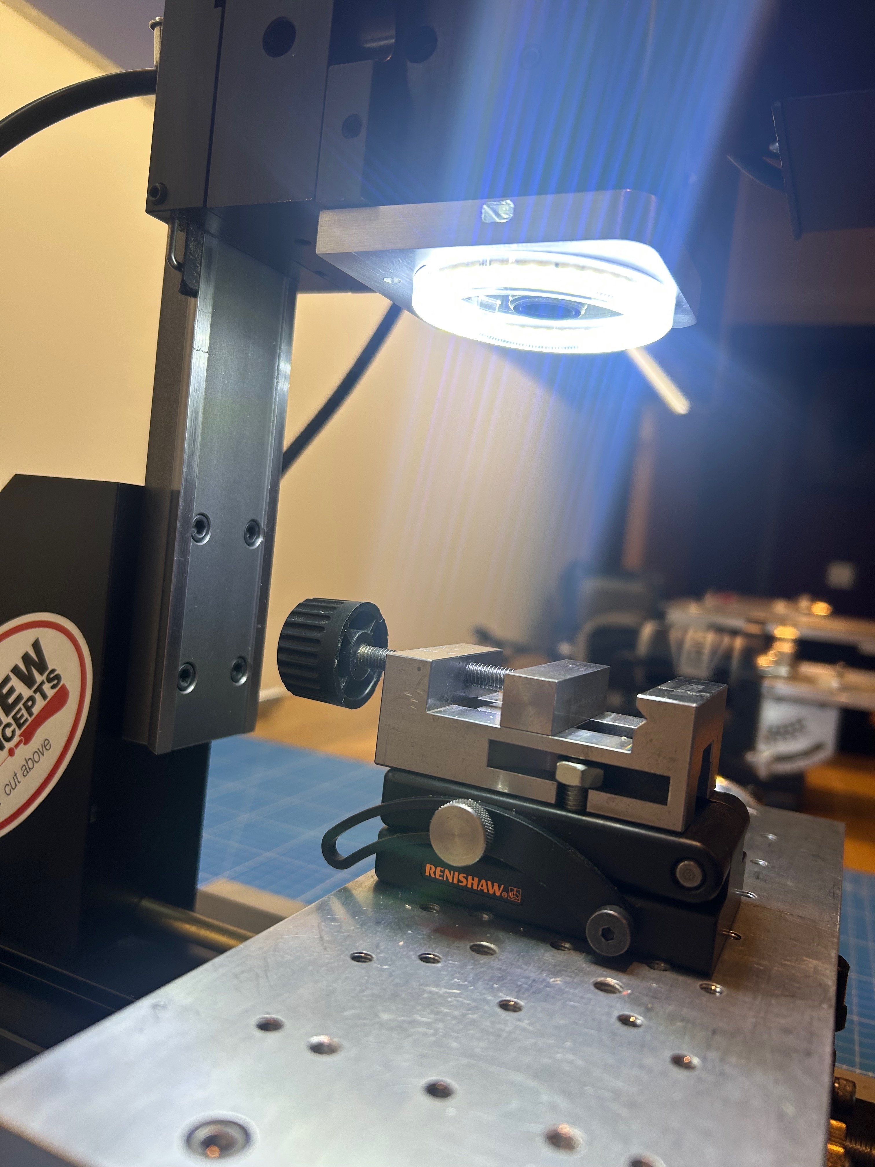
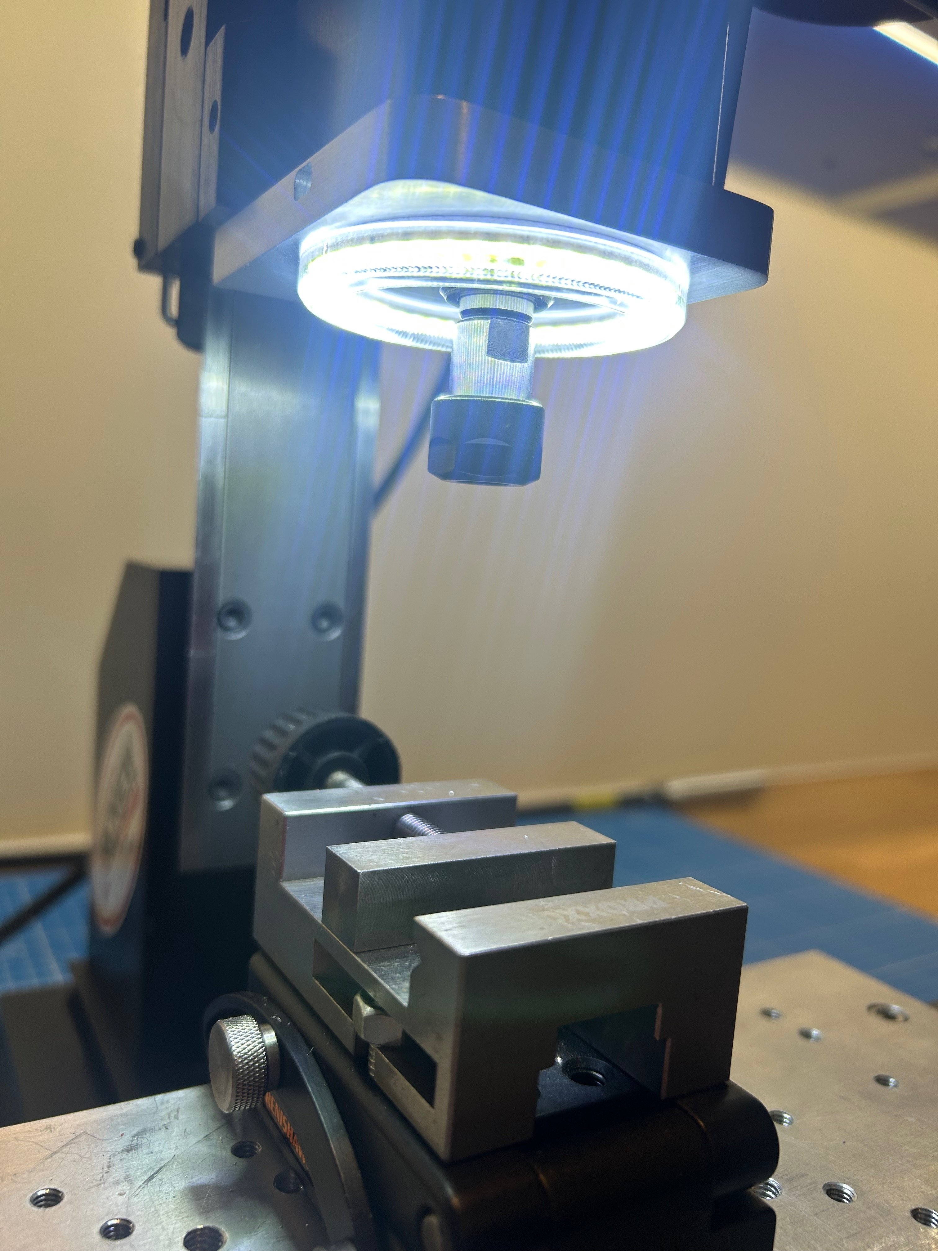
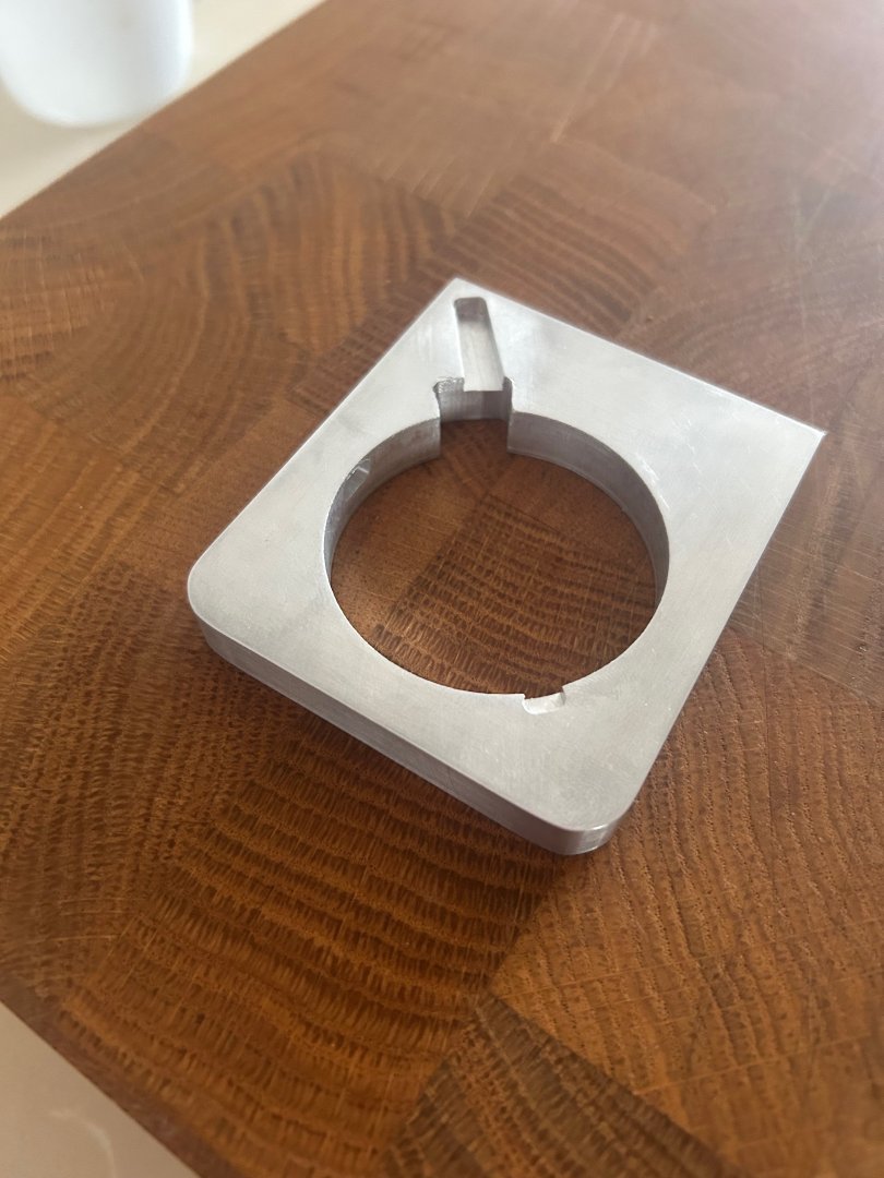
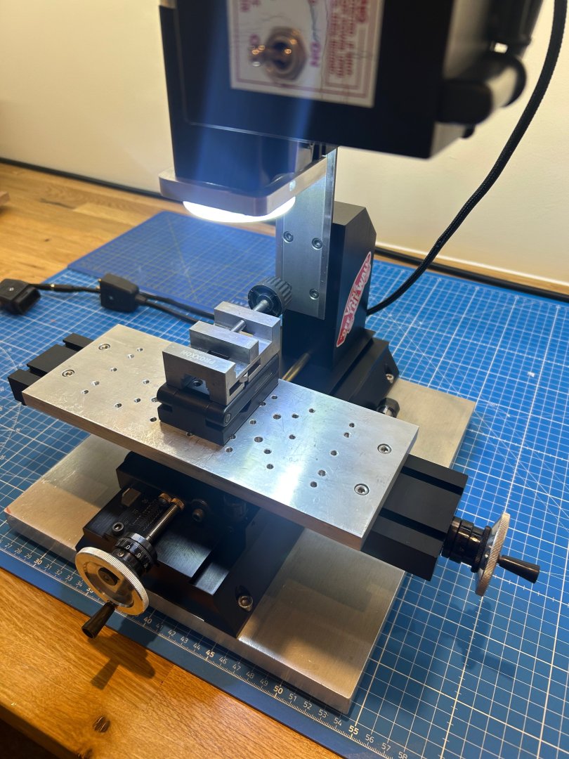
Hi All I know that a few builders on here use a Sherline mill as do I. I have found that my eyesight needs more light as I get older so I have wanted for a while to make a decent ring light for my mill. I found some cheap 60mm ring lights that run on 12/24v that seemed to be about the right size. Unfortunately it couldn't be directly attached to the mill head as it would remove any access to the Tommy bar spindle hole. So a carrier was required and I bashed this up out of 10mm aluminium. The slot allows the wiring to travel up through the mill head which is already there. It keeps the look of it wiring free I milled a small slot each side to allow for the Tommy bar to reach the spindle Its held in place with double sided tape And the wiring is encased in polyester braiding to try and make it look as though it has always been there The results are really good I hope this helps someone or gives a bit of inspiration to make the lighting on your mill a bit better - Anyway I can now get back to ship building instead of filling my workshop with aluminium swarf!! Mark


-
L'Amarante by marsalv - 1:36 - POF
No Idea replied to marsalv's topic in - Build logs for subjects built 1501 - 1750
Love the details on the beams - the dovetails are perfect. -
I too have had some very disappointing days during my build and things can get disheartening. Take a few days and it always seems better. I think your build was coming along beautifully. I hope you do get to finish this ship 👍
-
Keep going mate you’re doing a great job these timbers are particularly difficult to make. 👍👍
-
That looks great 👍 The transition is very smooth and much better than the step that I arrived at - top job
-
Very well found my friend - I’m going to leave mine as it is as breaking those shiplap planks out would destroy them all. At least your ship will be spot on 👍
-
Hi Tobias - I think that you are right and I completely missed that! I have just had a look at Adrians book and he has missed this point as well. It will be interesting to see what Gerard says but either way I think that using these planks to help the transition would look very nice.
-
HMS ANSON 1781 by albert - 1/48 - 64 guns
No Idea replied to albert's topic in - Build logs for subjects built 1751 - 1800
Albert your work is truly inspirational - Its not just that - its the way you have your workshop and how you approach your work - fantastic -
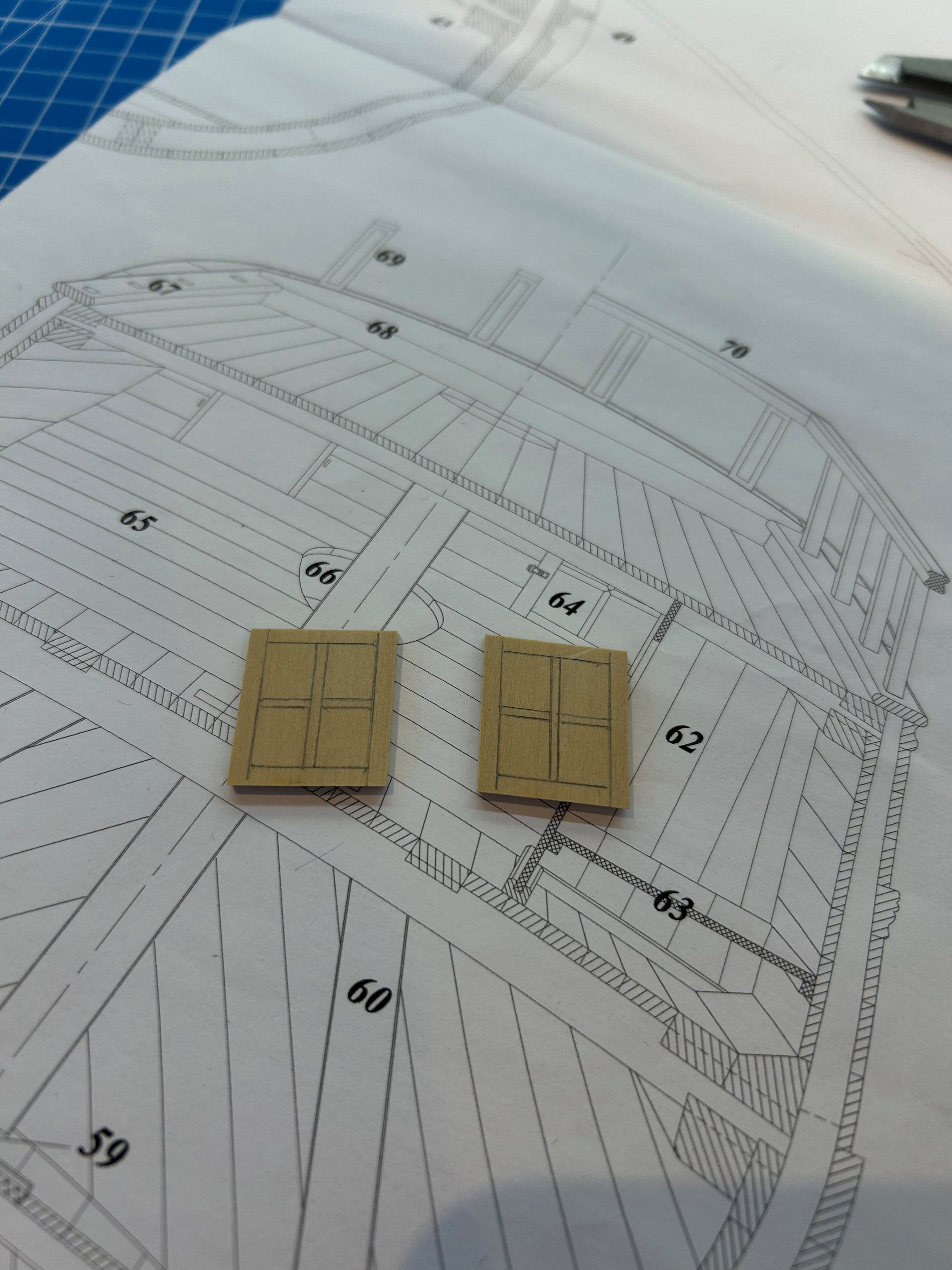
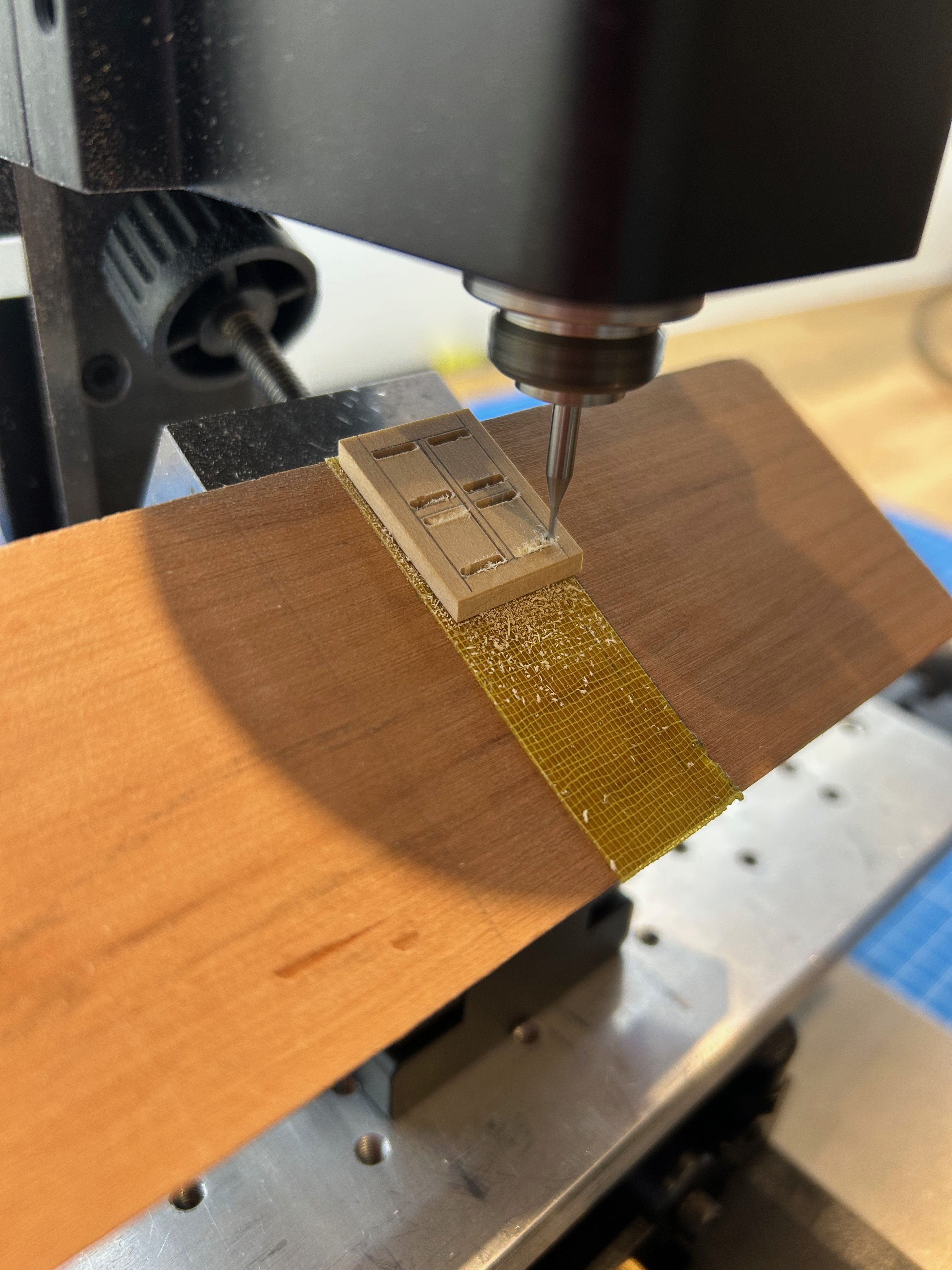
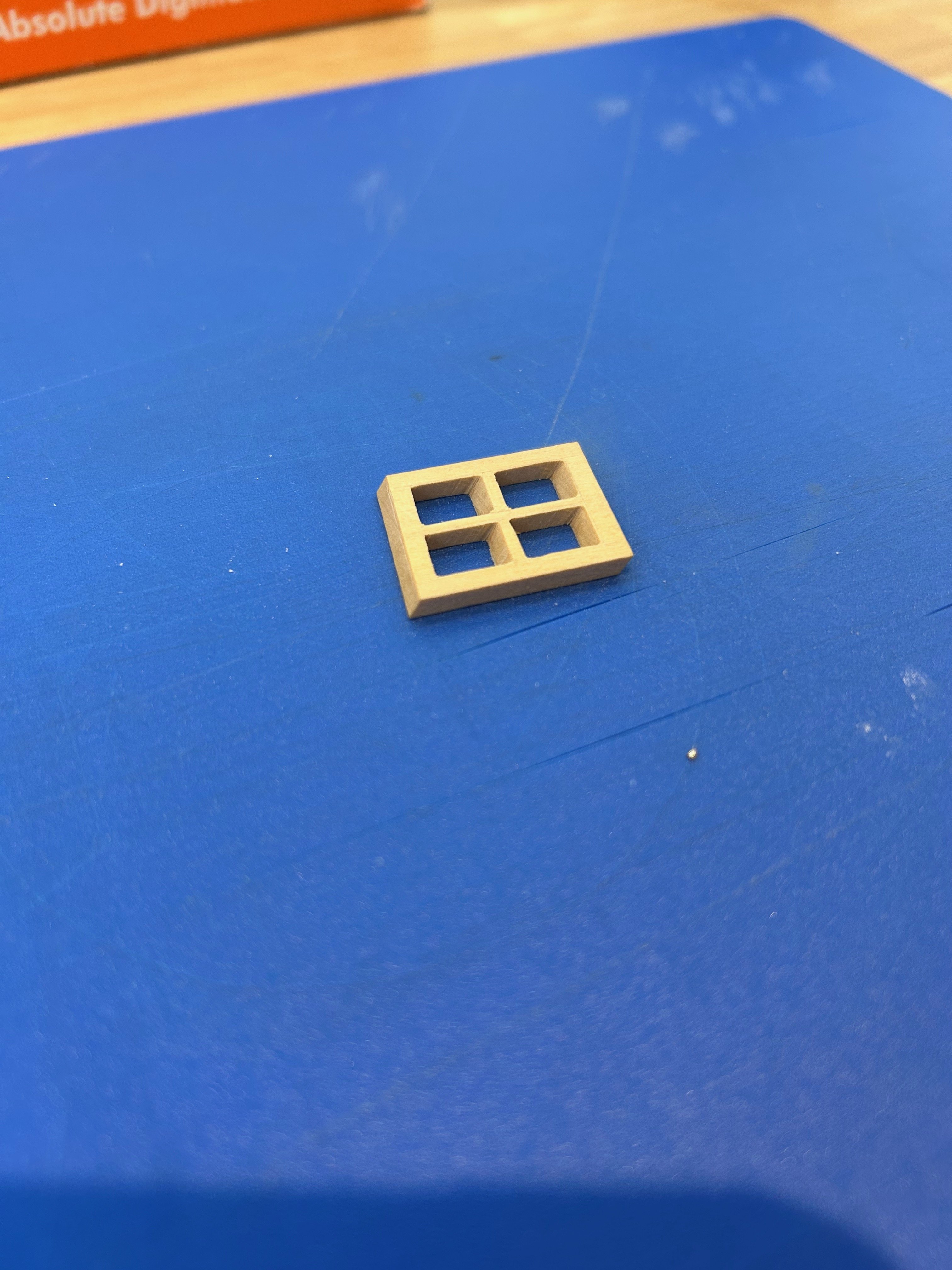
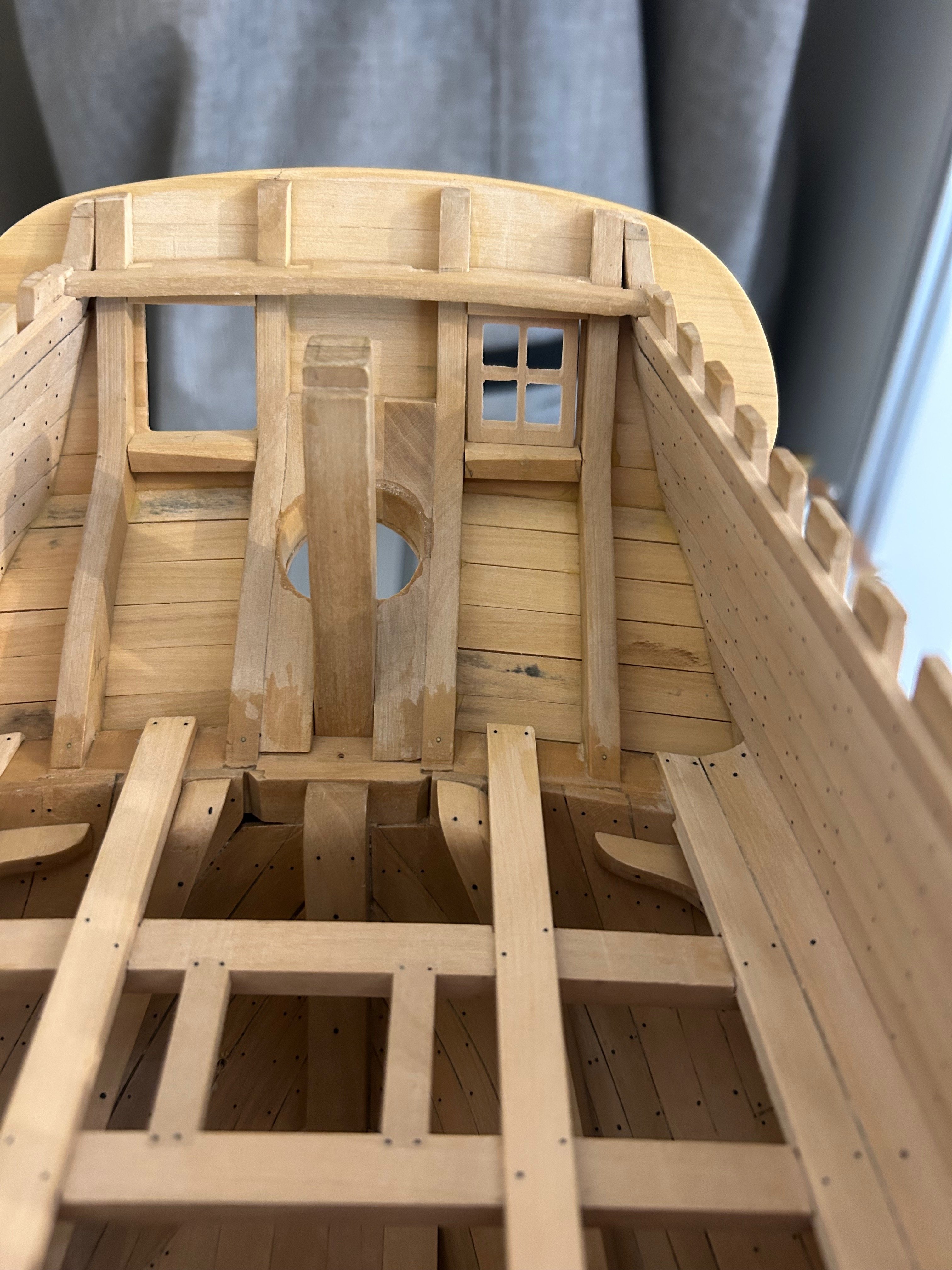
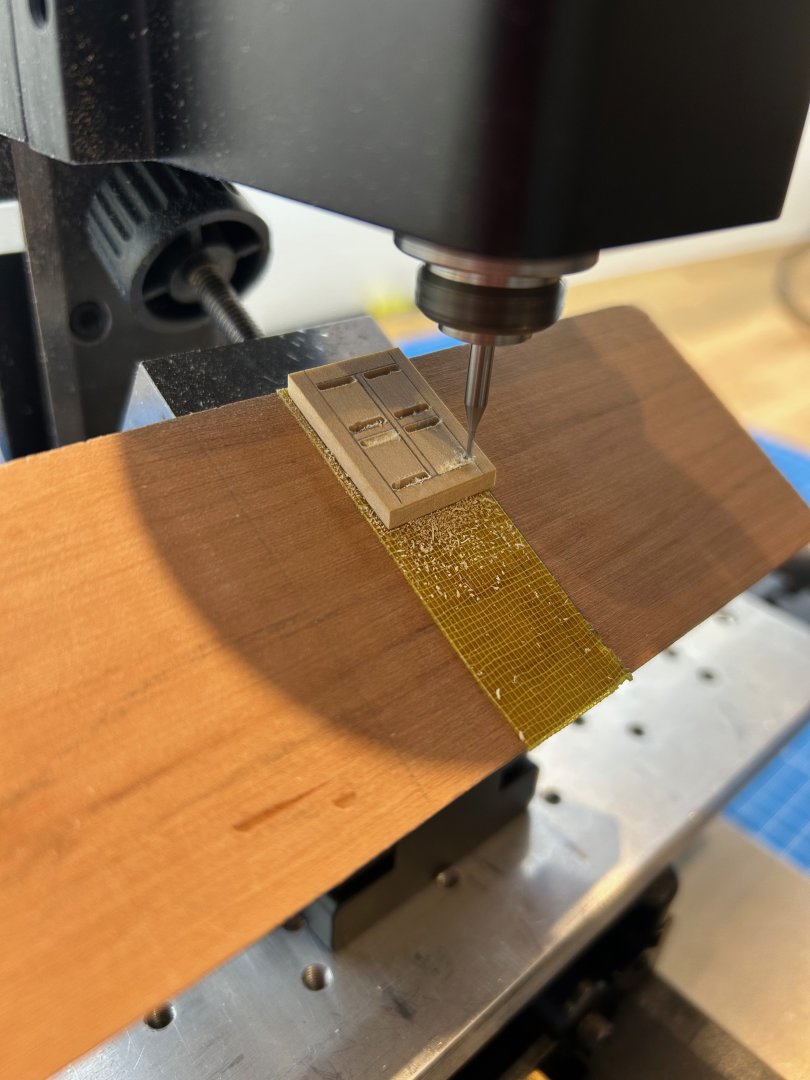
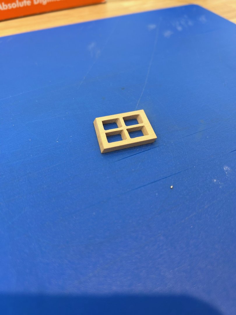
I've been trying to figure out how best to make the windows as they are a parallelogram in shape but also all of the parts are angled to suit the angle of the stern. I tried a few mock ups using separate parts but they really did not go well at all. So I thought that the best way was to try and mill them out of a single piece. So I marked them up to roughly match the drawing Then I set the required angle and using a 1mm mill bit I cut the windows out. The result actually isn't too bad - sorry about the poor quality pictures and I just balanced it into the ship to give a rough idea of how it looked. One down although it needs tiding up and one to go. I can then complete the window frames and plank the inside to tidy it all up. Mark

-
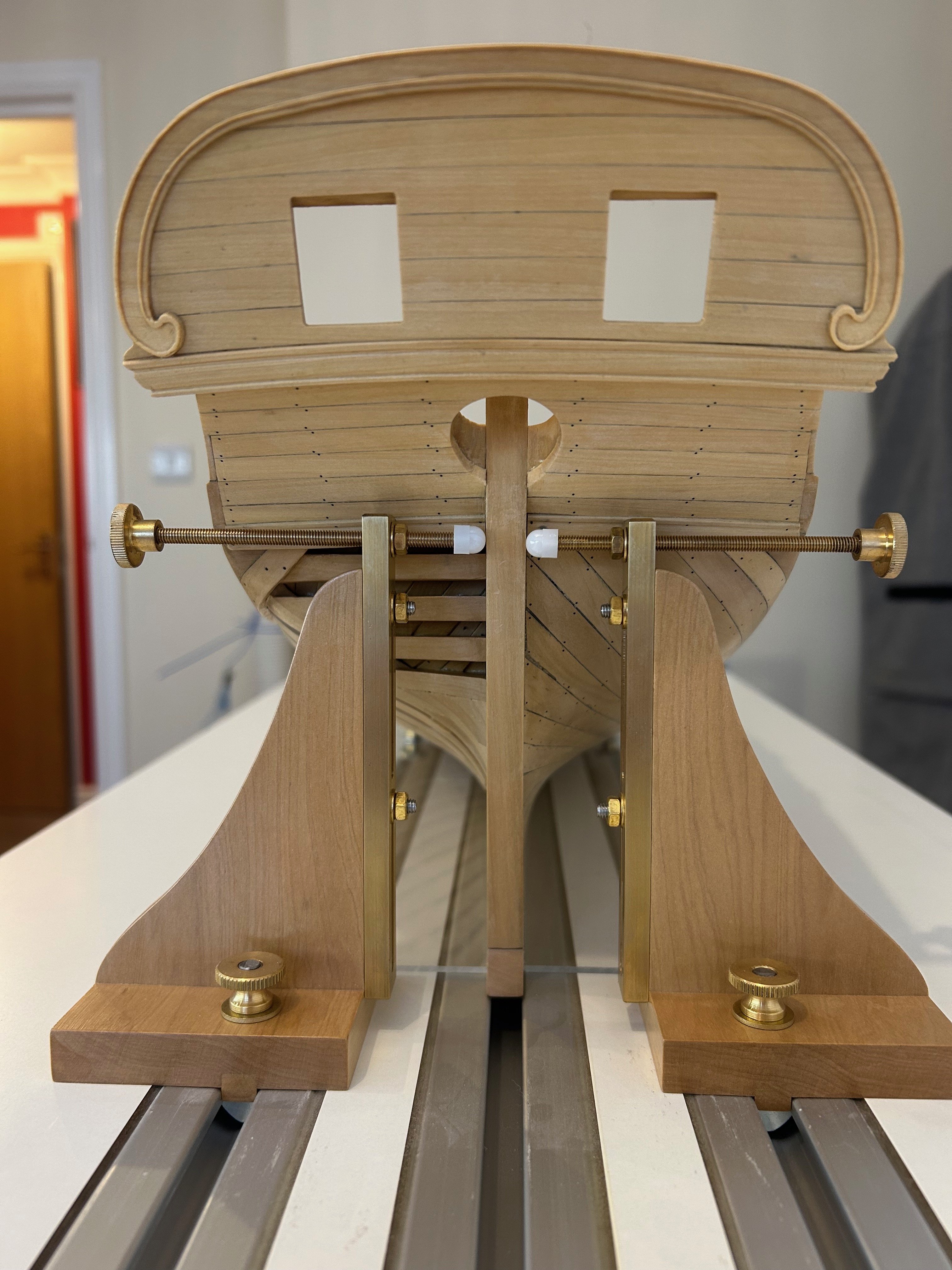
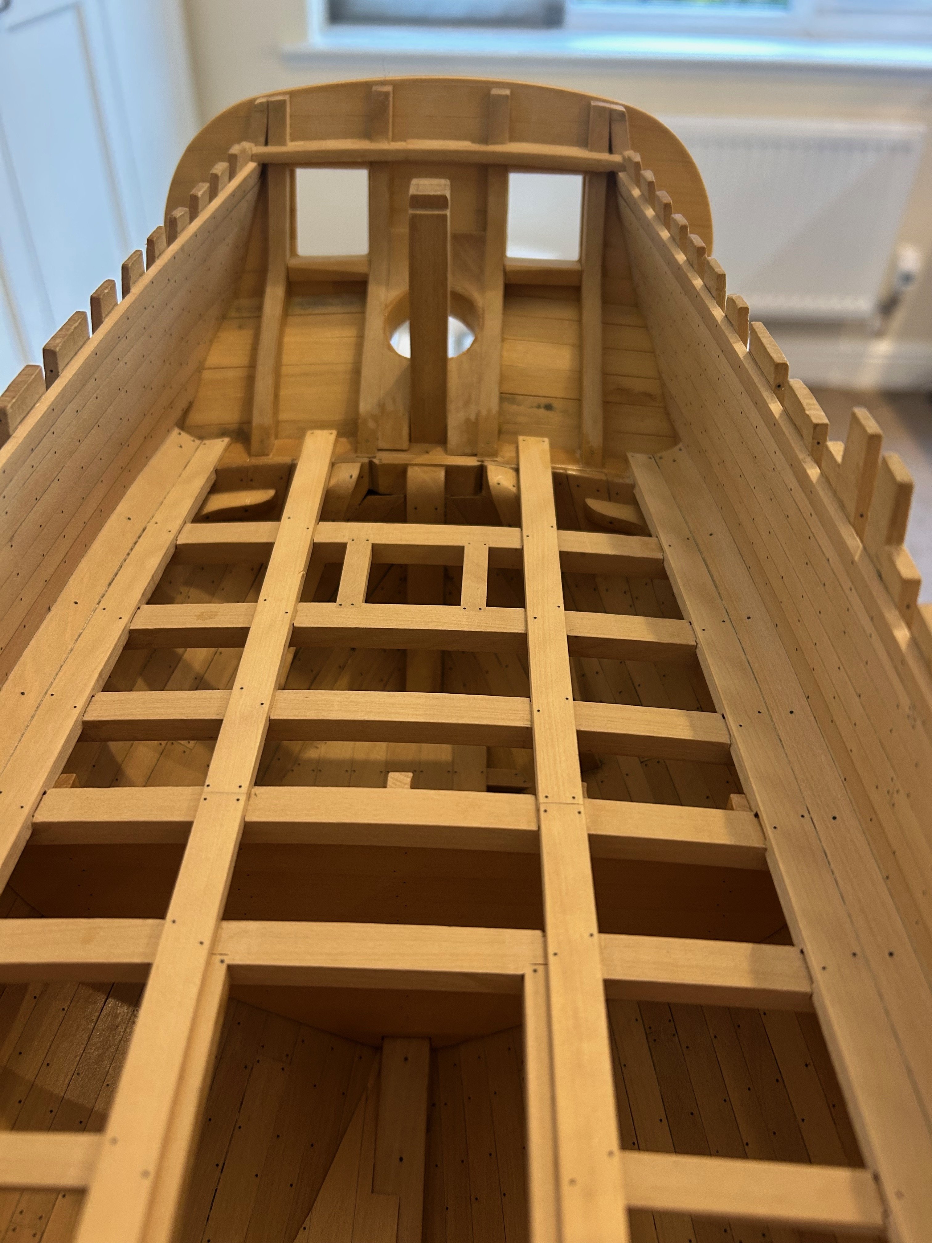
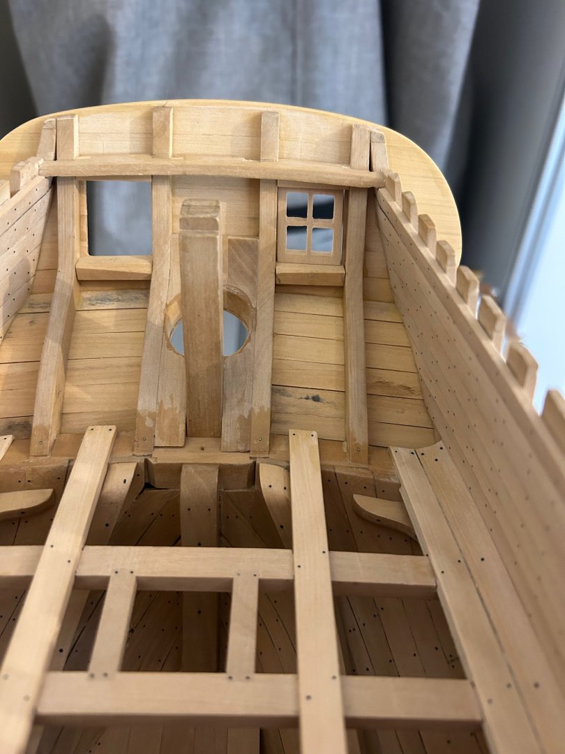
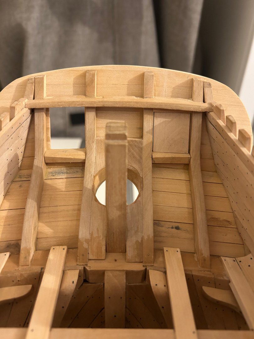
So moving forward I have now fitted the stern timbers and generally tidied the stern up. I'm really pleased with the way it looks and I think it's fairly symmetrical too. But as with everything it seems with ship building, I soon discovered that the very rear beam that I fitted maybe 2 years ago is 2mm too low. It's not a problem but it will need a filler piece on the top fitted at some point. I also found that my location of the counter timbers was not as good as it could have been as the windows did not exactly line up with them. Again it's not a problem but I do have to make some extra pieces to hide these errors. The stern windows were my next task - The drawings more hint at their design rather than give a detailed instruction. As such I did what I always do and contacted Gerard Delacroix and asked his opinion. He advised me that their parallelogram shape on the outside followed through to the inside windows. He also went above and beyond and sent me a drawing of how they should look - cheers mate 👍 So to keep the shape I made a couple of false windows to set the window frames. I really want this part of the ship to look correct hence all of the questions and effort. Below you can see the false window in place whist the frame sets. The cheeks of the window frames also require some extra timber but thats ok and I'll sort that out too. I have decided to have them closed but I'm going to make them as best I can anyway. Here's a picture of both windows with the top and bottom parts of the frames in place. So the next jobs are to complete the window cheeks and work out how to make the windows so that they look as near to the drawings as I can. Thanks all for the very nice comments - Mark

-
Such nice work 👍. If you want to see if you are filing the surfaces flat - just get a pencil and scribble all over the surface. Then file again and see if the marks are removed. This worked for me - keep the updates coming!
-
Hi - No sorry I didn’t take any but I achieved the bead by making a scraper out of an old blade. You are right though about working against the grain the wood is difficult to cut
-
I that case you could use either - as for the choice of ply you need a well made and bonded ply. Just have a look at the edge of the ply you may buy; it should be solid without voids or crumbly layers
-
Are you going to paint the hull or leave it as wood?
-
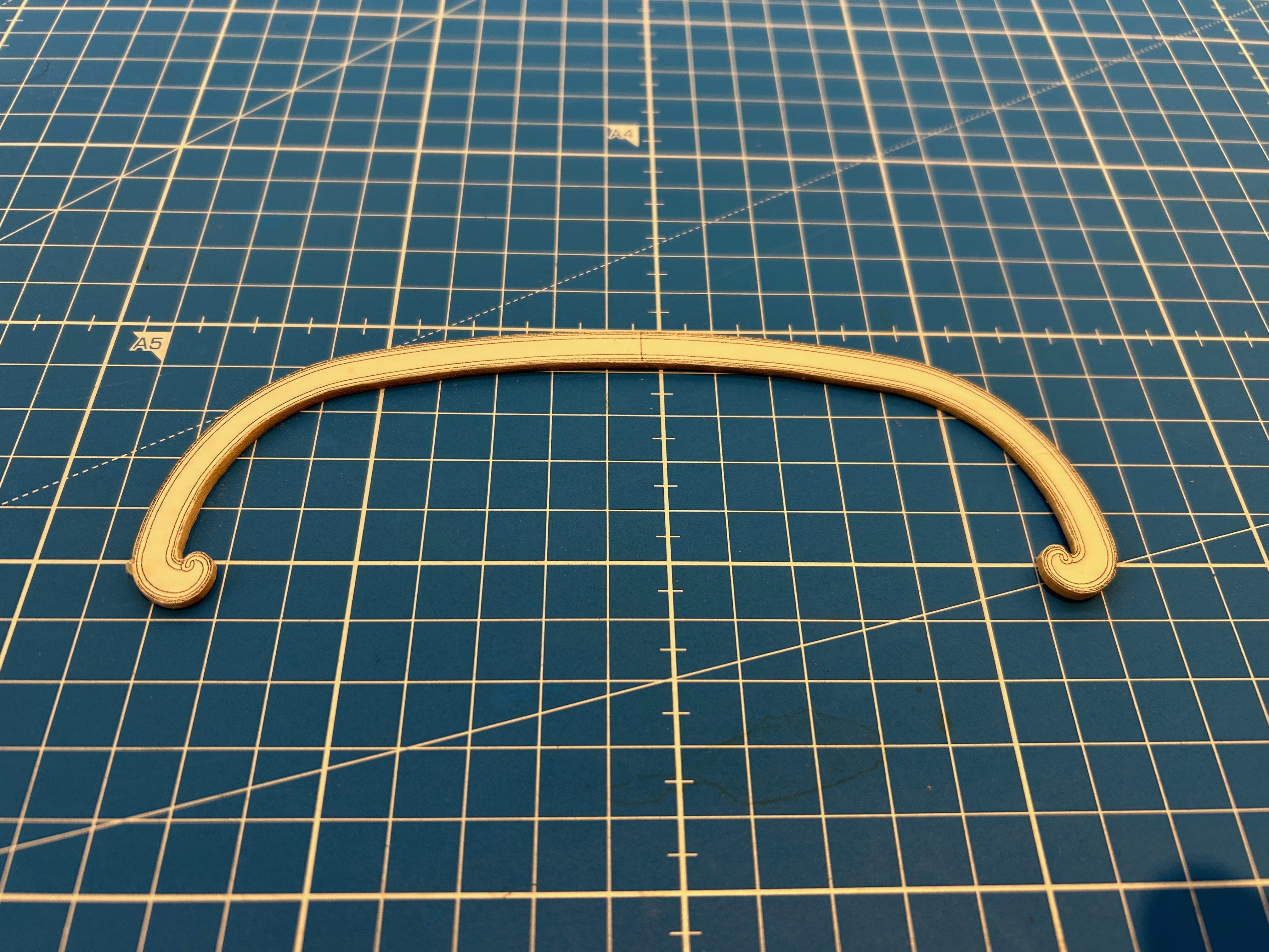
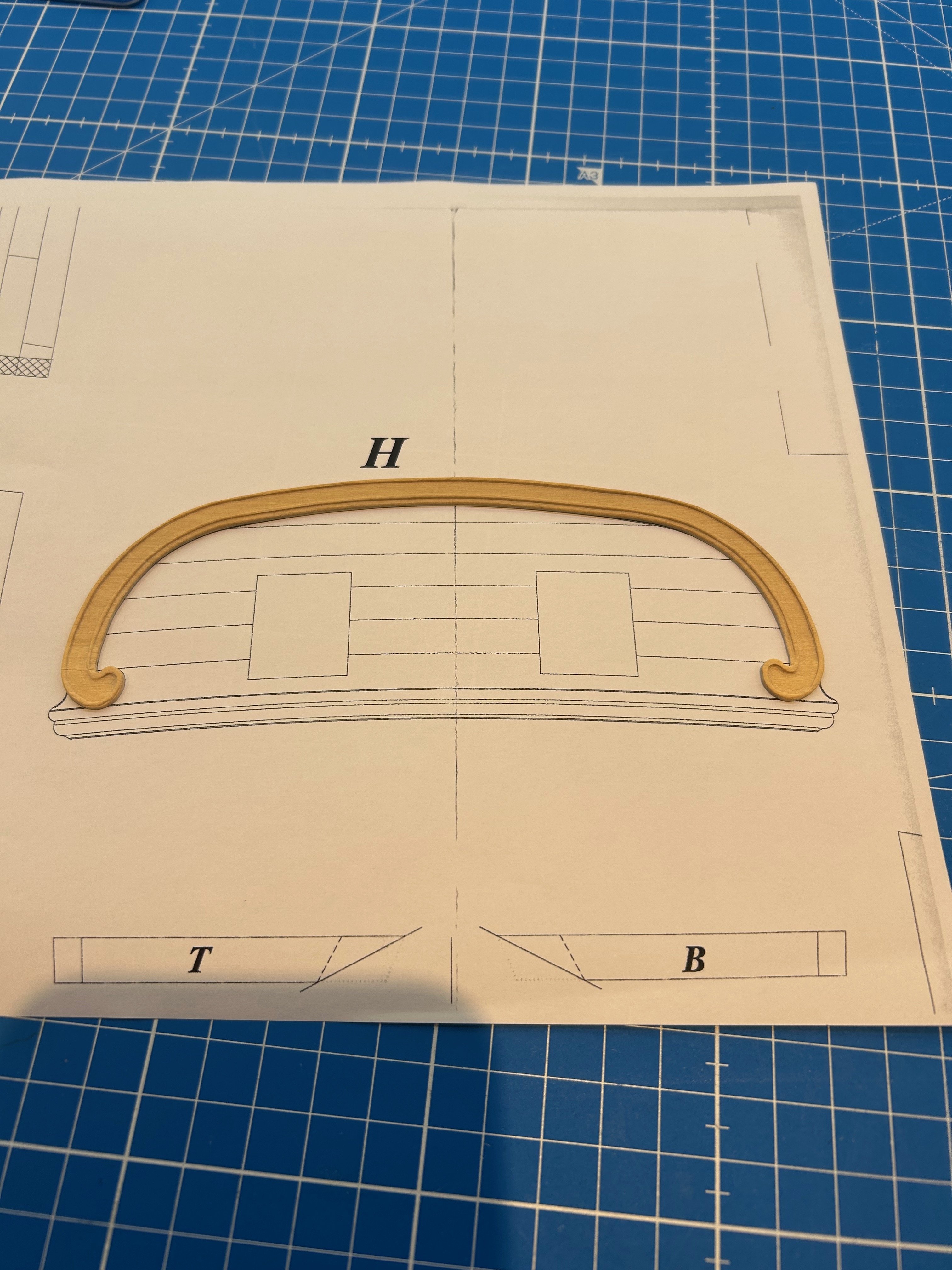
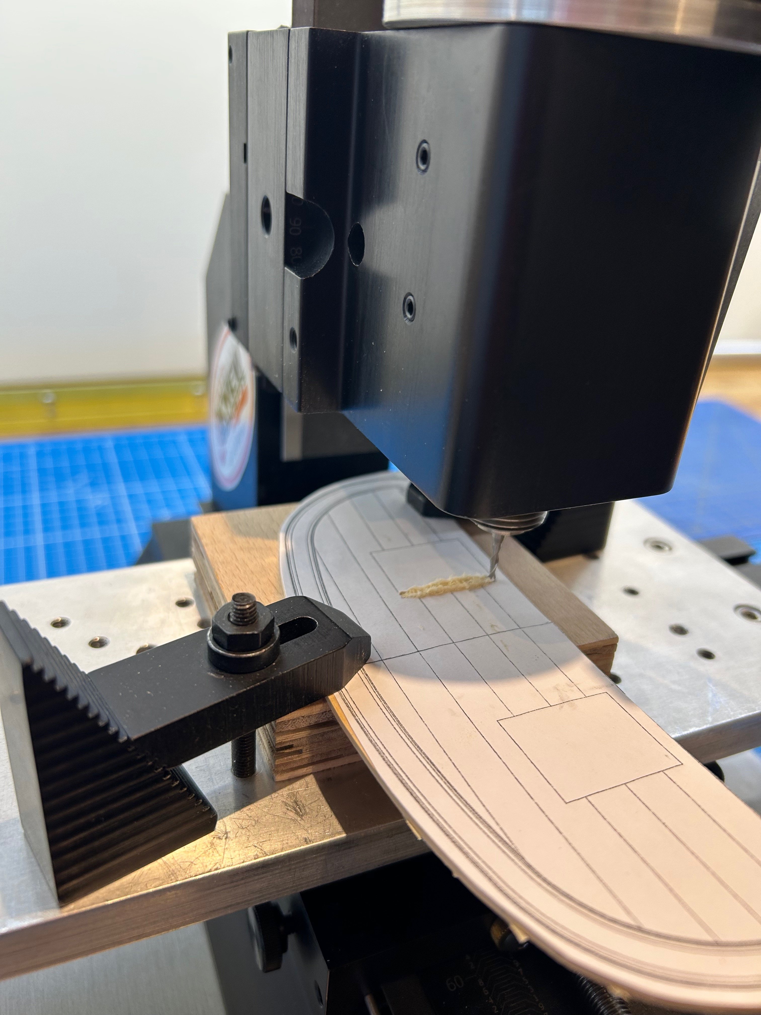
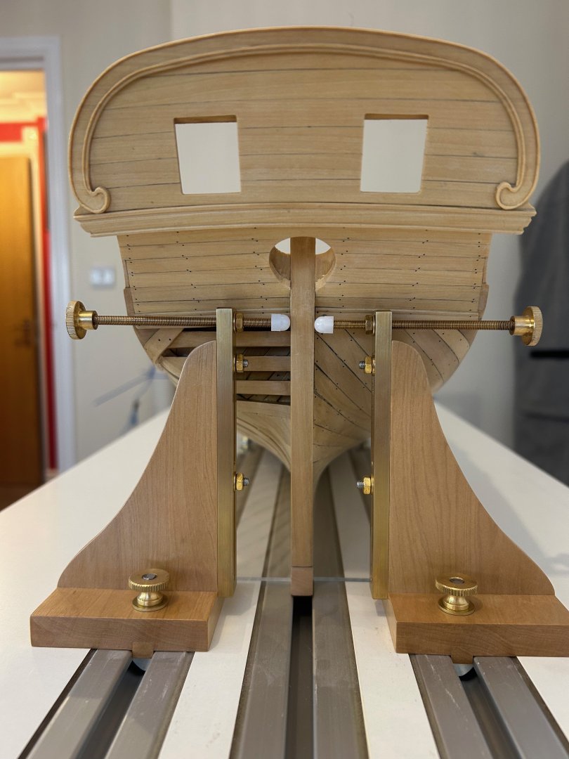
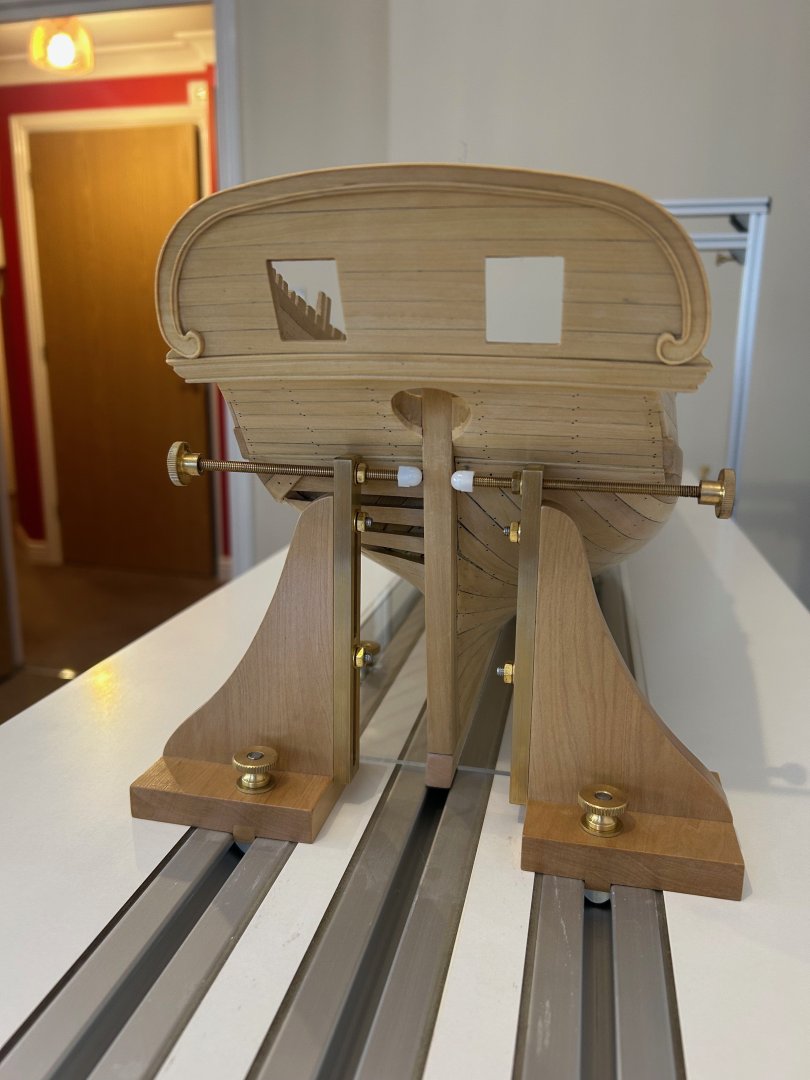
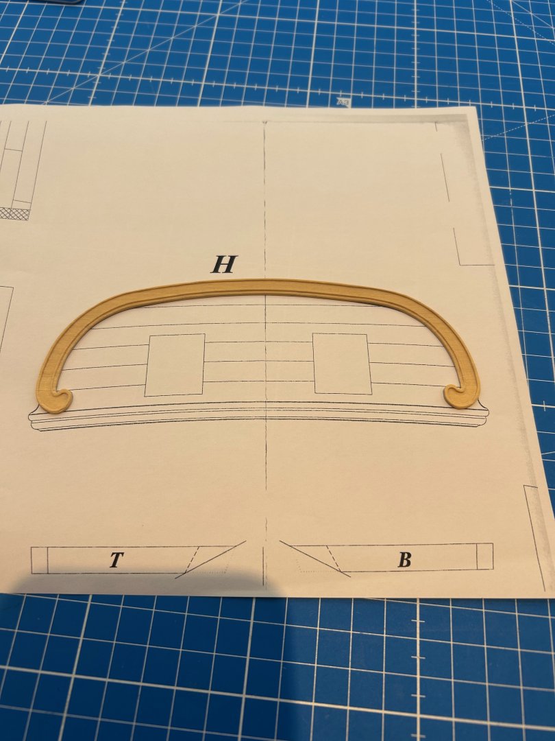
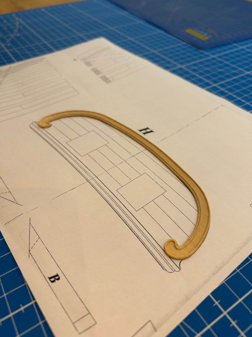
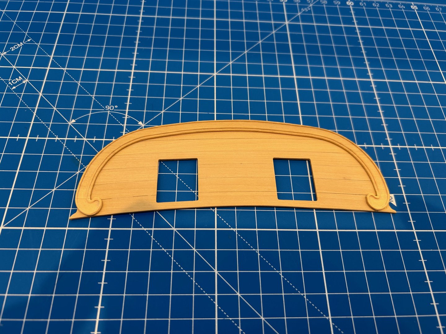
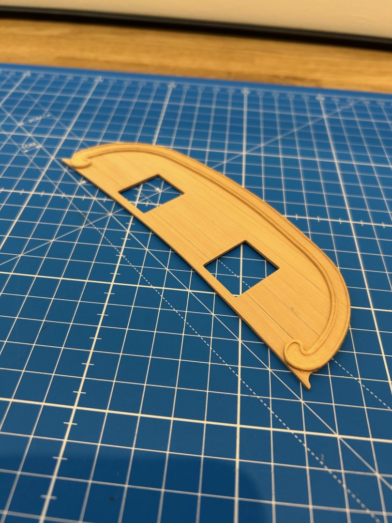
Hi All I've had some more time so I've been getting on with the stern. I decided to go with the curved planks that I had previously made but I did break off the top two planks and replace them. It was really easy to do and I just reused my jig to make this happen. Moving forward there is a carved moulding which goes around the stern. It's quite basic compared to many ships which was a bonus for me as I have never tried to make anything like this before. So as per usual I made a photocopy template and cut out the basic shape. And now the fun started - Using a mixture of scrapers and chisels I went ahead and tried to replicate how it should look. I'm no carver thats for sure and I could not replicate the very fine detail but I gave it a go. This is pretty much as good as it gets from me so I decided to use this first version. Hopefully my carving will improve as I learn this skill more. Next was to mill out the windows - I wanted to use the mill so that I could get the shape as correct as possible. However they could easily be cut out using a fret saw and files. The two parts now glued together - I'm going to fit this part to the counter timbers tomorrow and as long as nothing splits when I bend it all should be OK. If not I'll have a rethink on how to approach this part of the ship. Thanks for all of the comments - Mark


-
Byrnes Table Saw on Ebay UK
No Idea replied to No Idea's topic in Modeling tools and Workshop Equipment
Well..............Its had a bid. I feel sorry for the buyer as they could import a brand new saw into the UK for £750 including taxes and shipping -
Byrnes Table Saw on Ebay UK
No Idea replied to No Idea's topic in Modeling tools and Workshop Equipment
If that’s true that’s amazing news 👍👍 -
Mike that is genius; what a great way of achieving your needs - even better you are only producing wood shavings instead of dust 👍
- 943 replies
-
- 3
-

-
- hahn
- oliver cromwell
- (and 1 more)