No Idea
-
Posts
1,036 -
Joined
-
Last visited
Content Type
Profiles
Forums
Gallery
Events
Everything posted by No Idea
-
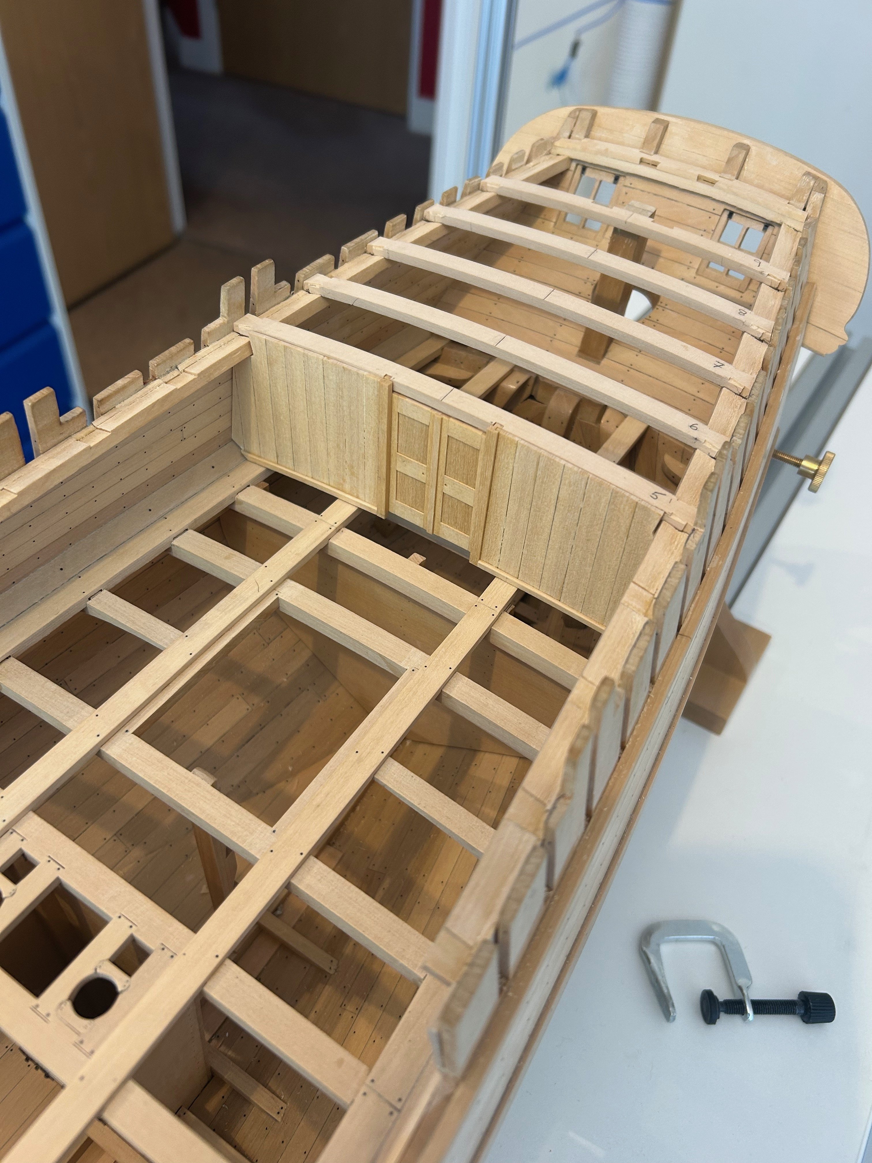
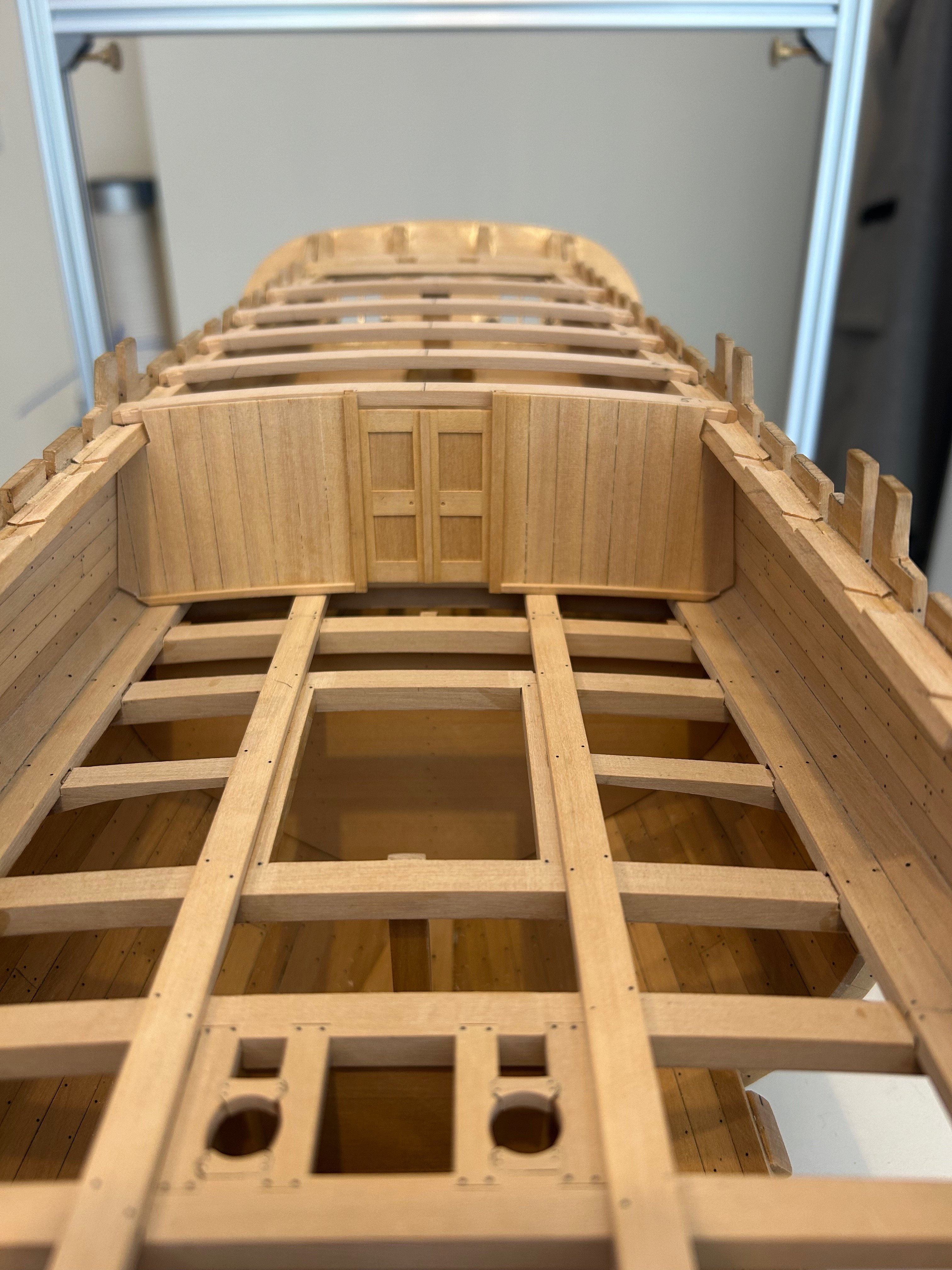
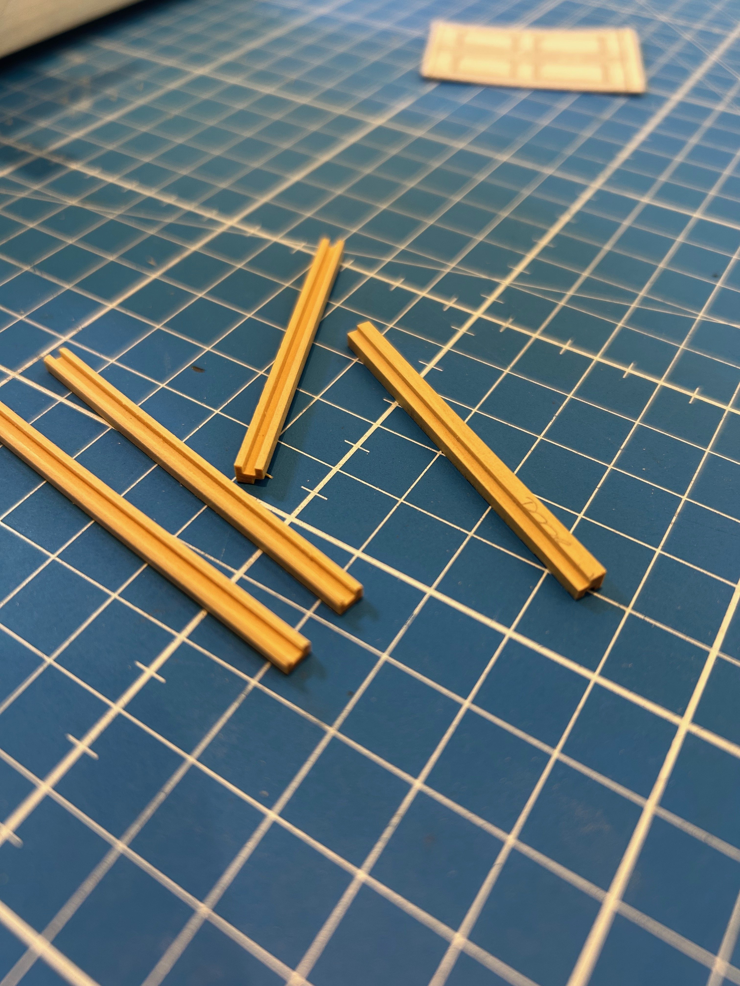
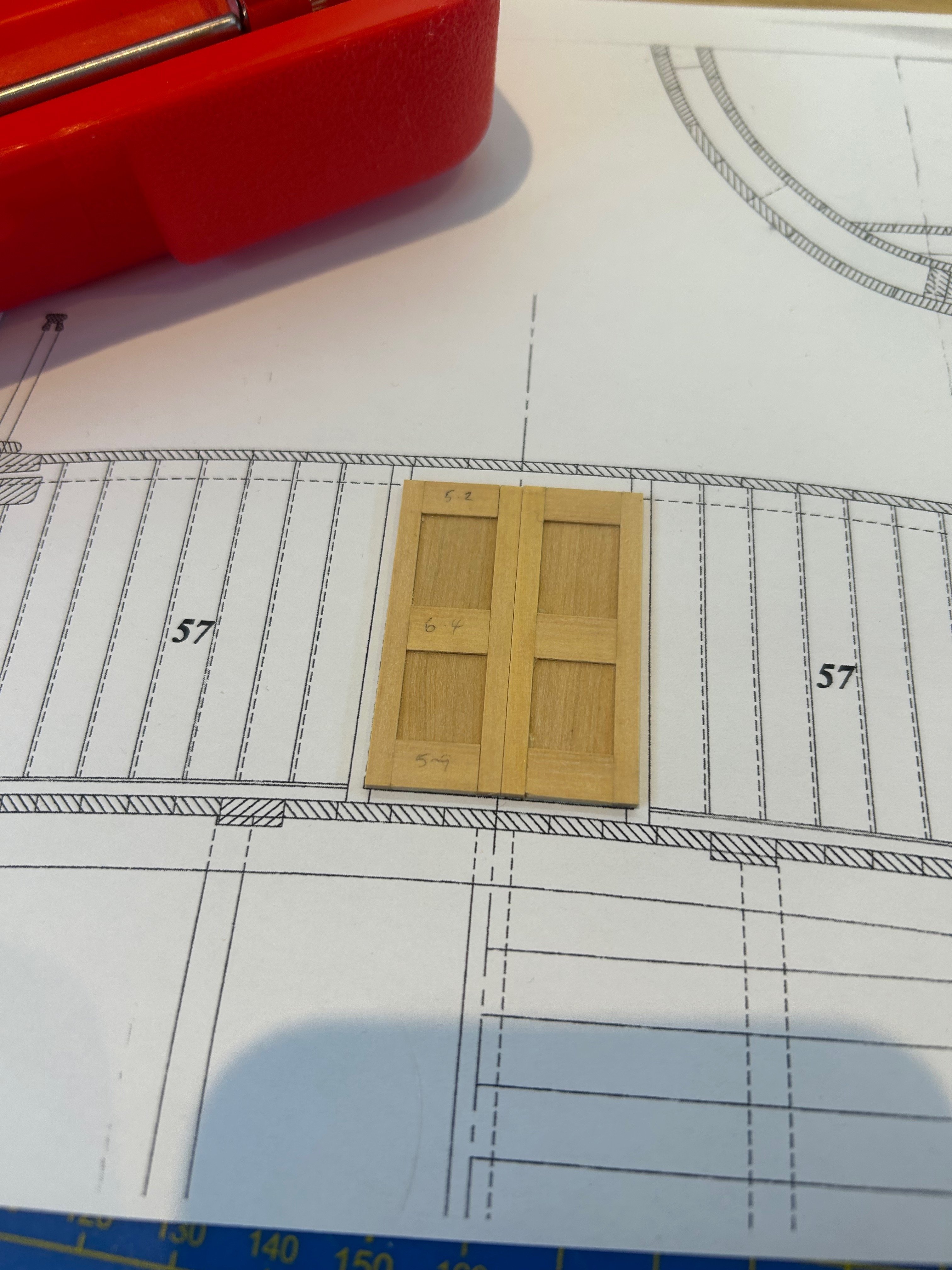
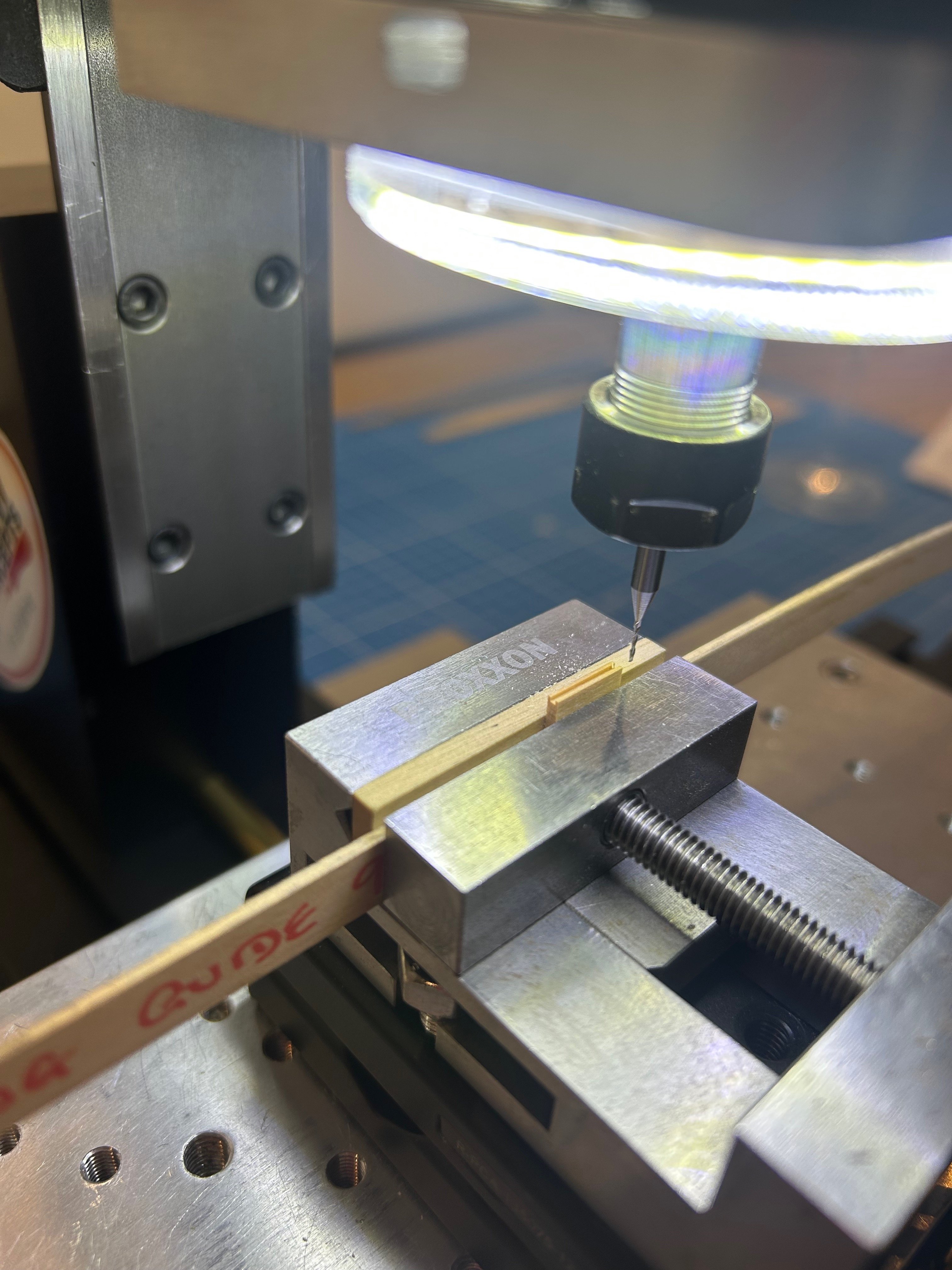
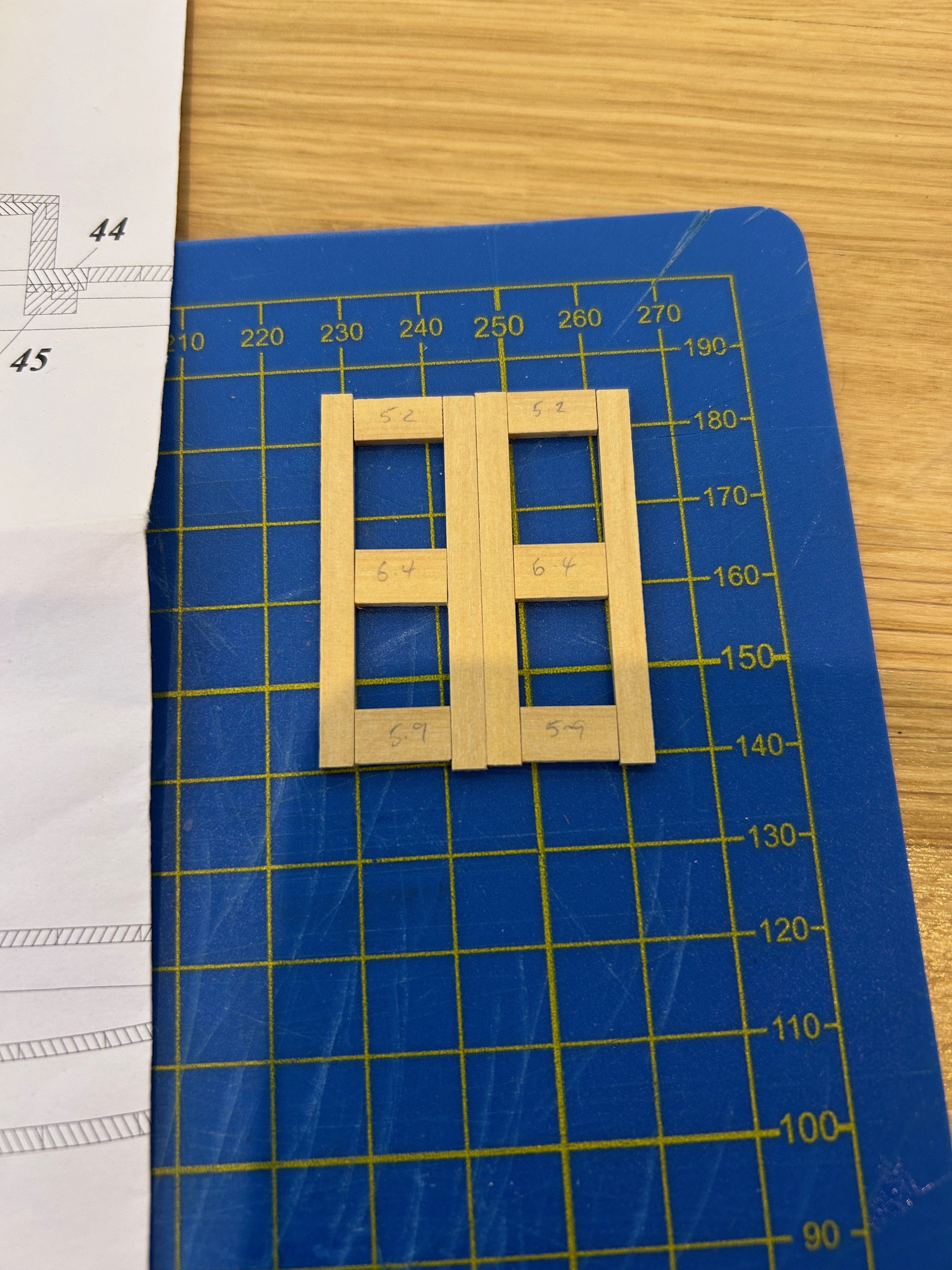
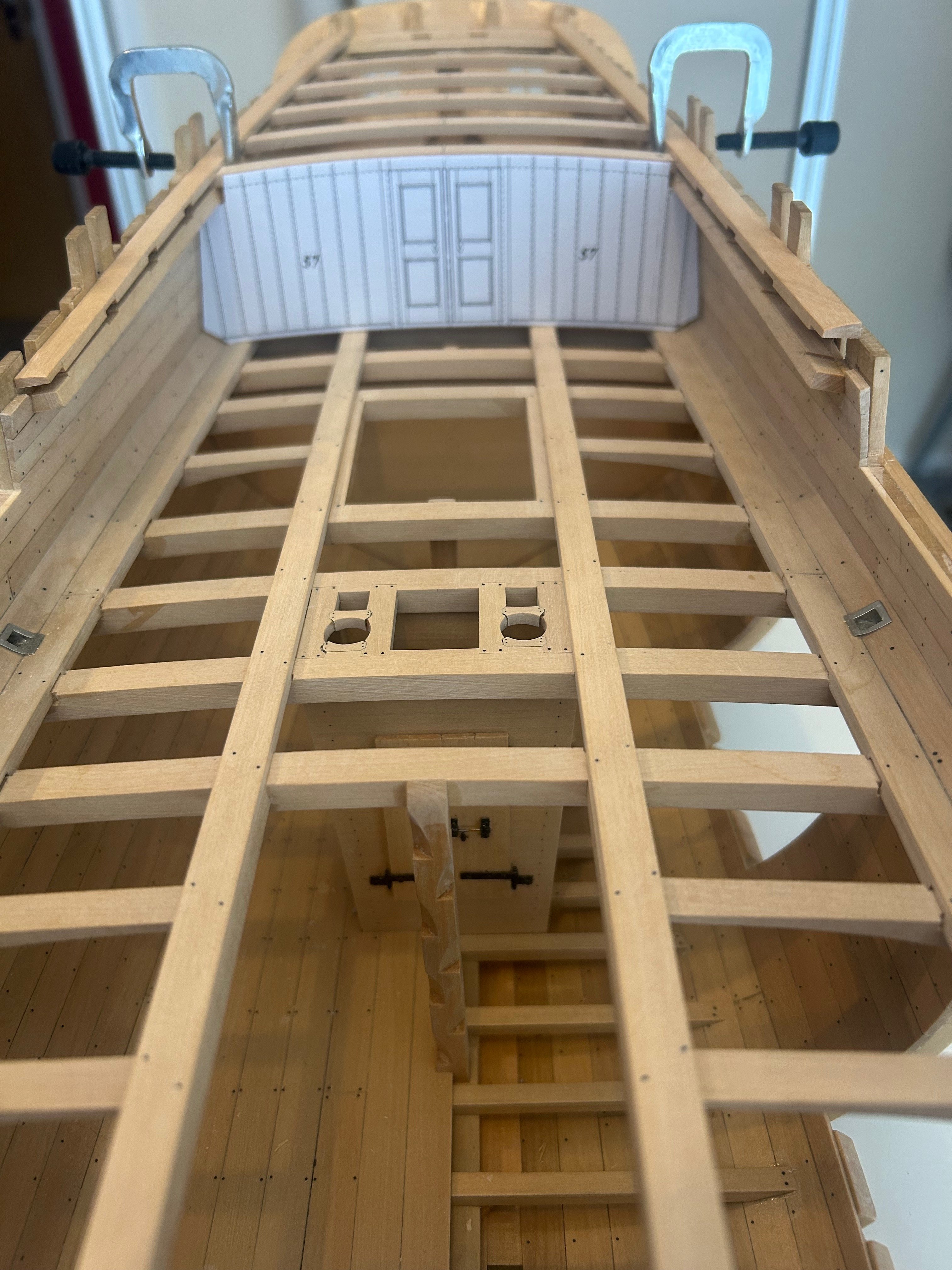
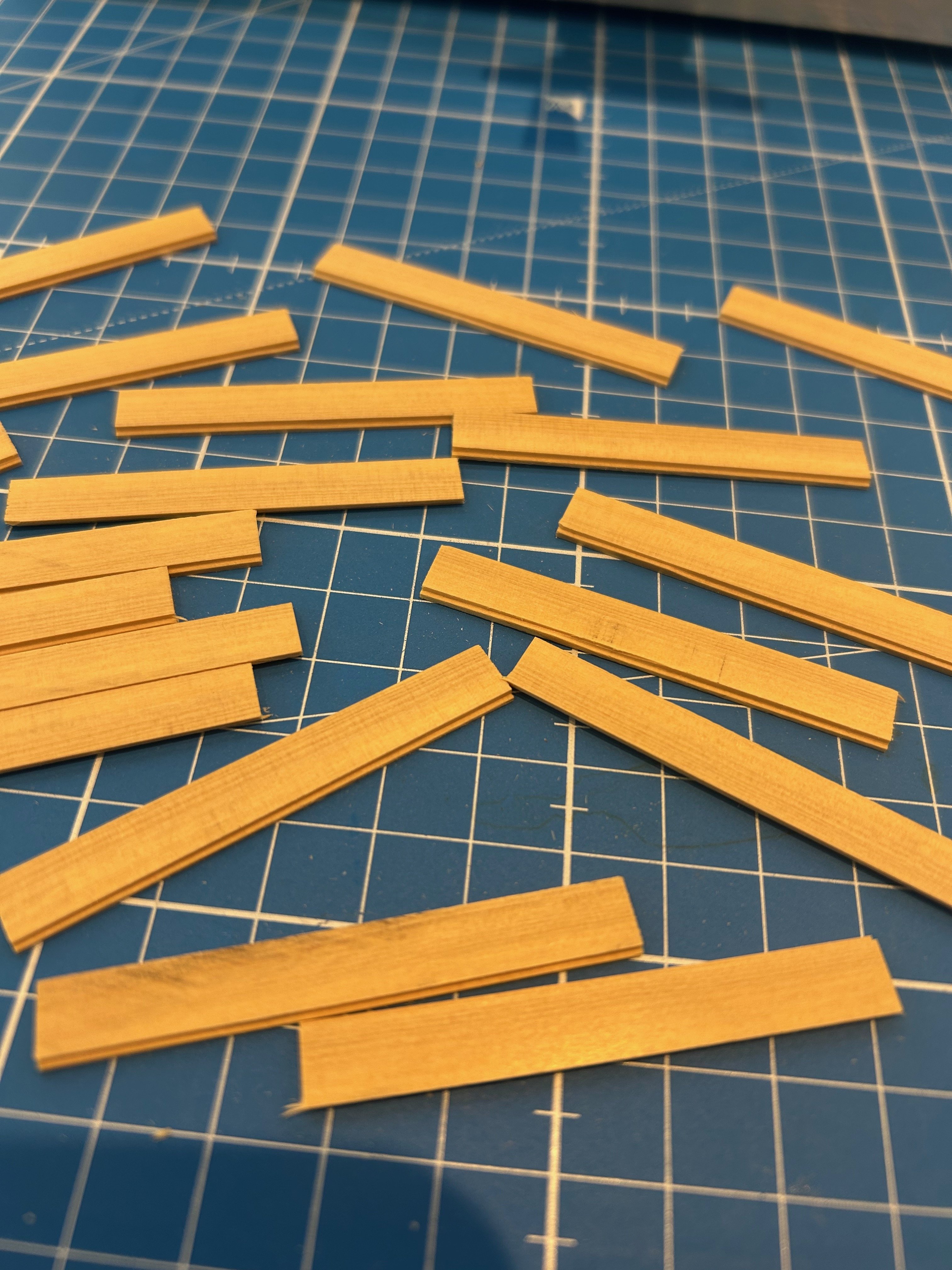
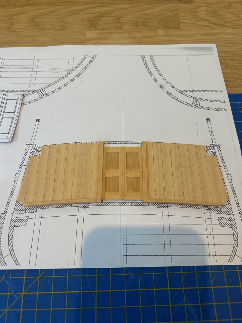
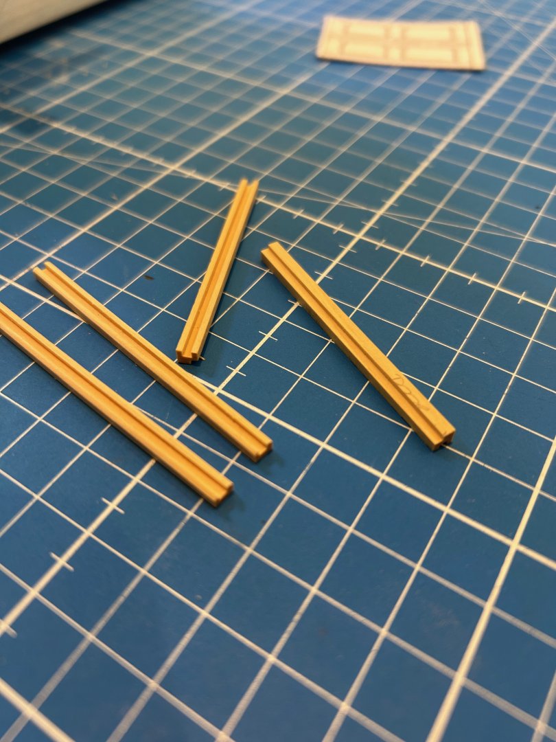
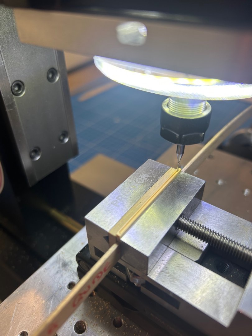
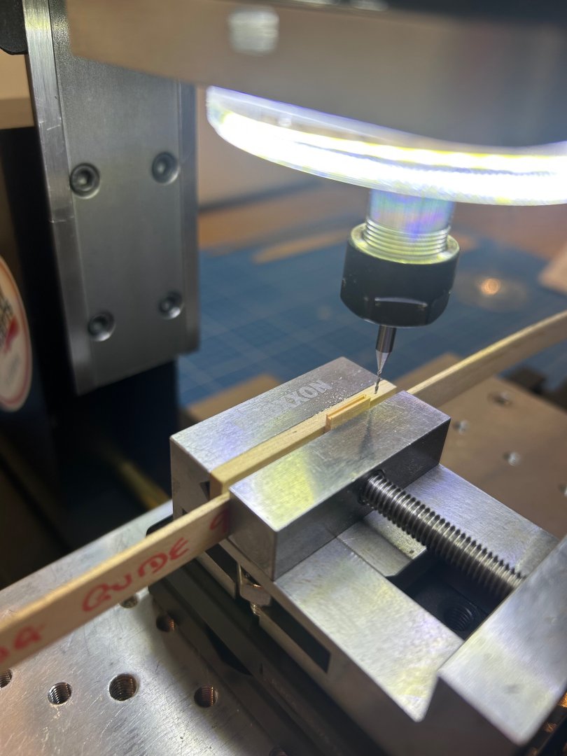
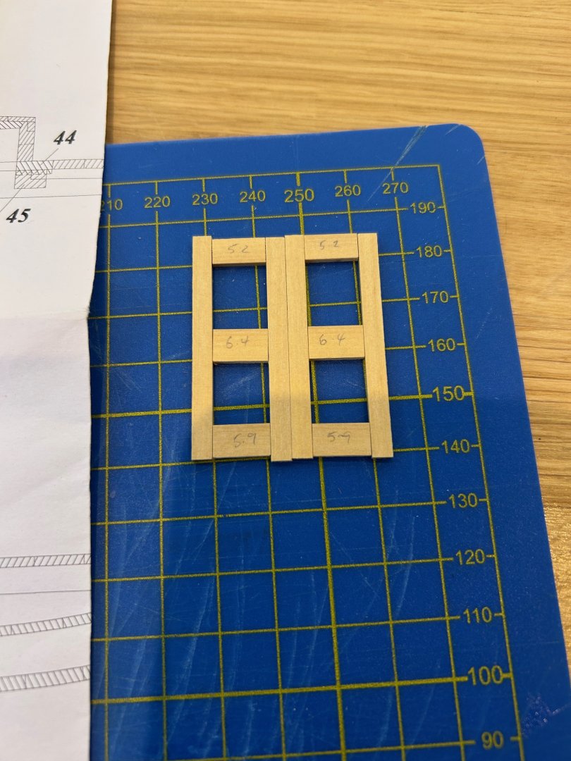
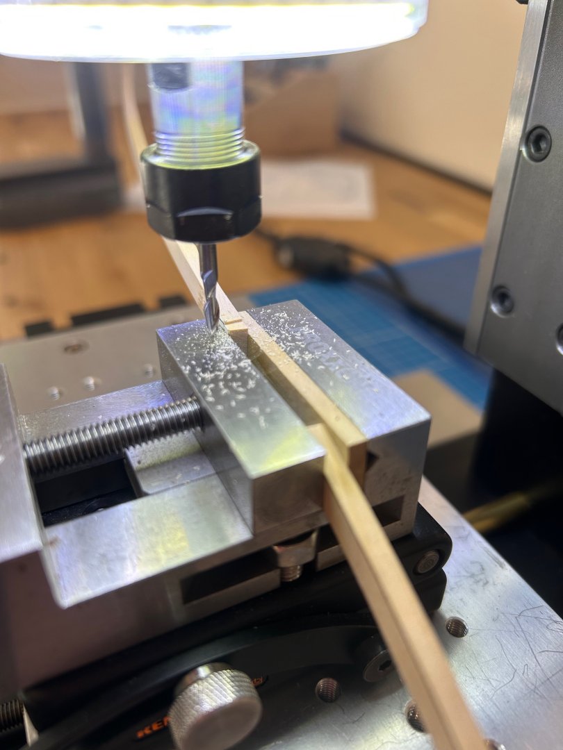
 Hi all Back from our lovely holiday and straight back onto Le Rochefort I'm now working on the crews quarters below the quarter deck and have started with the bulkhead which has a double entry door. This is quite a feature on this ship so I want to get it as good as possible. I started by making the shiplap planks that form the walls which I then glued together to make the actual walls. Next was to look at the doors themselves - I usually just get a solid piece of wood and then mill out the features to make them look like doors. In this instance I thought that I would try a new exercise for me and make them from individual parts and include all of the relevant joints as they possibly would have been made originally. Each frame is made of 5 pieces which then require 4 inserts in each door. Milling out the rebates to fit the 0.7mm inserts Sorry I should have taken more pictures but here are how the doors turned out. Assembling the parts actually proved to be one of the hardest parts. Next I needed to make the door frame uprights which have 2 rebates cut into them and also the base rebate that the walls slot into. It all took a little bit of fettling to get all of the parts to fit correctly but I'm just about there now. I did have one issue and that was with the door frame uprights which stopped the whole assembly from sitting flush with the beam. This maybe because I miss read the drawings but to get around this issue I cut some rebates into the beam which actually makes the whole thing stronger and more stable It's all still a work in progress but I'm getting there with this particular part of the build. Mark
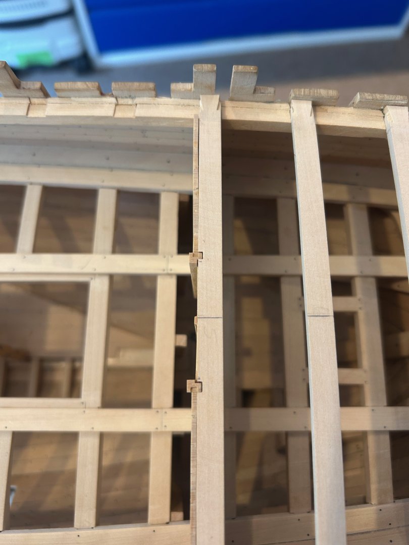


-
Gold solder for brass
No Idea replied to Richard Braithwaite's topic in Metal Work, Soldering and Metal Fittings
Silver solder on brass really needs tight joints to get a good joint. By the time it's been filed or sanded down it's almost invisible anyway. Jewellers use silver solder on gold and you cannot see the joint so I guess the secret is to take your time and have as little silver filler in the joint as possible -
They say that every day is a school day and this is one of mine. I would never have thought of that and my wife has an A3 light box for her art! I reckon that its going to spend more time in my workshop now - thanks Greg!
-
Greg your carpentry is amazing what a beautiful build
-
L'Amarante by marsalv - 1:36 - POF
No Idea replied to marsalv's topic in - Build logs for subjects built 1501 - 1750
Simply amazing work - wow -
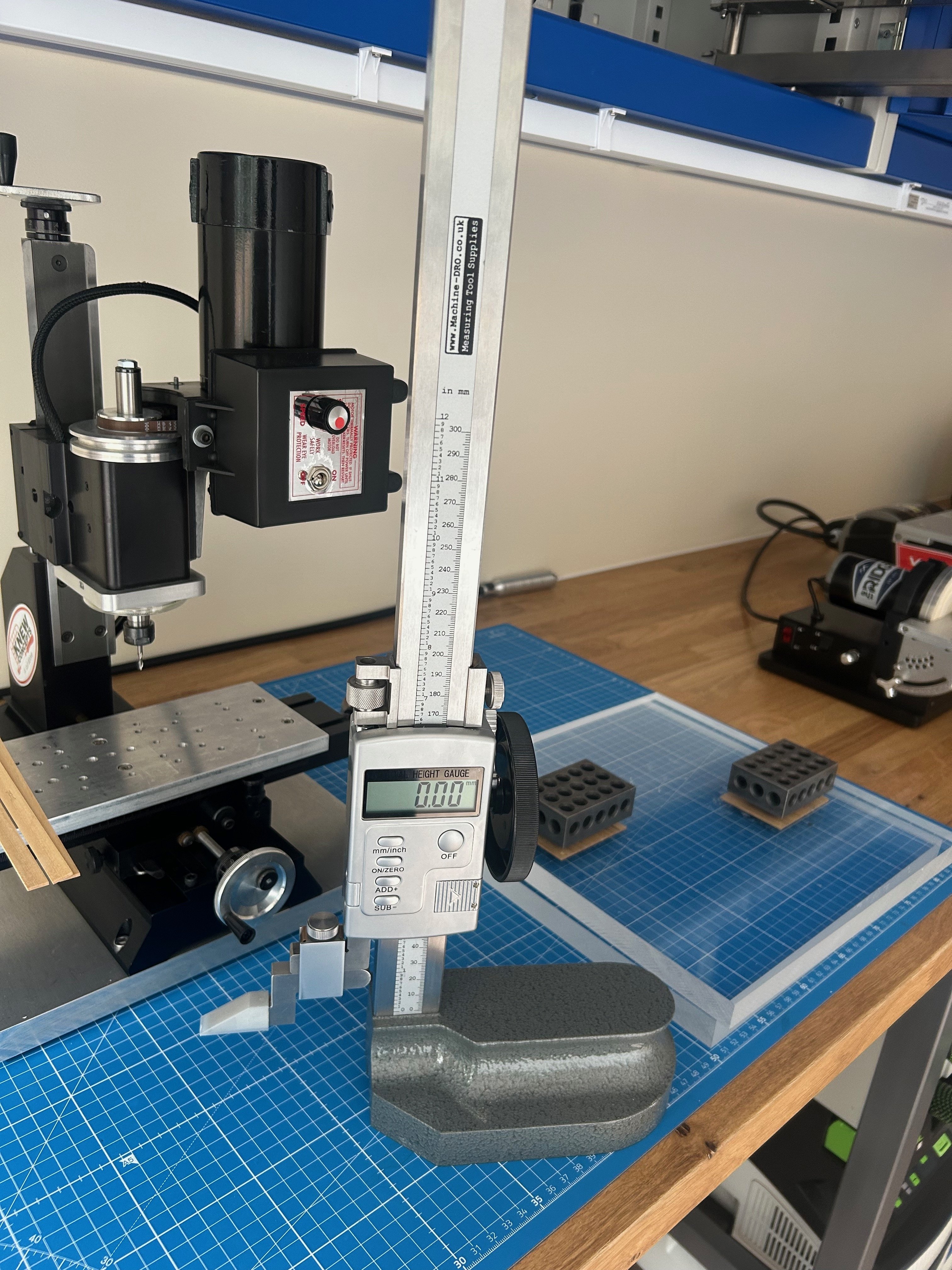
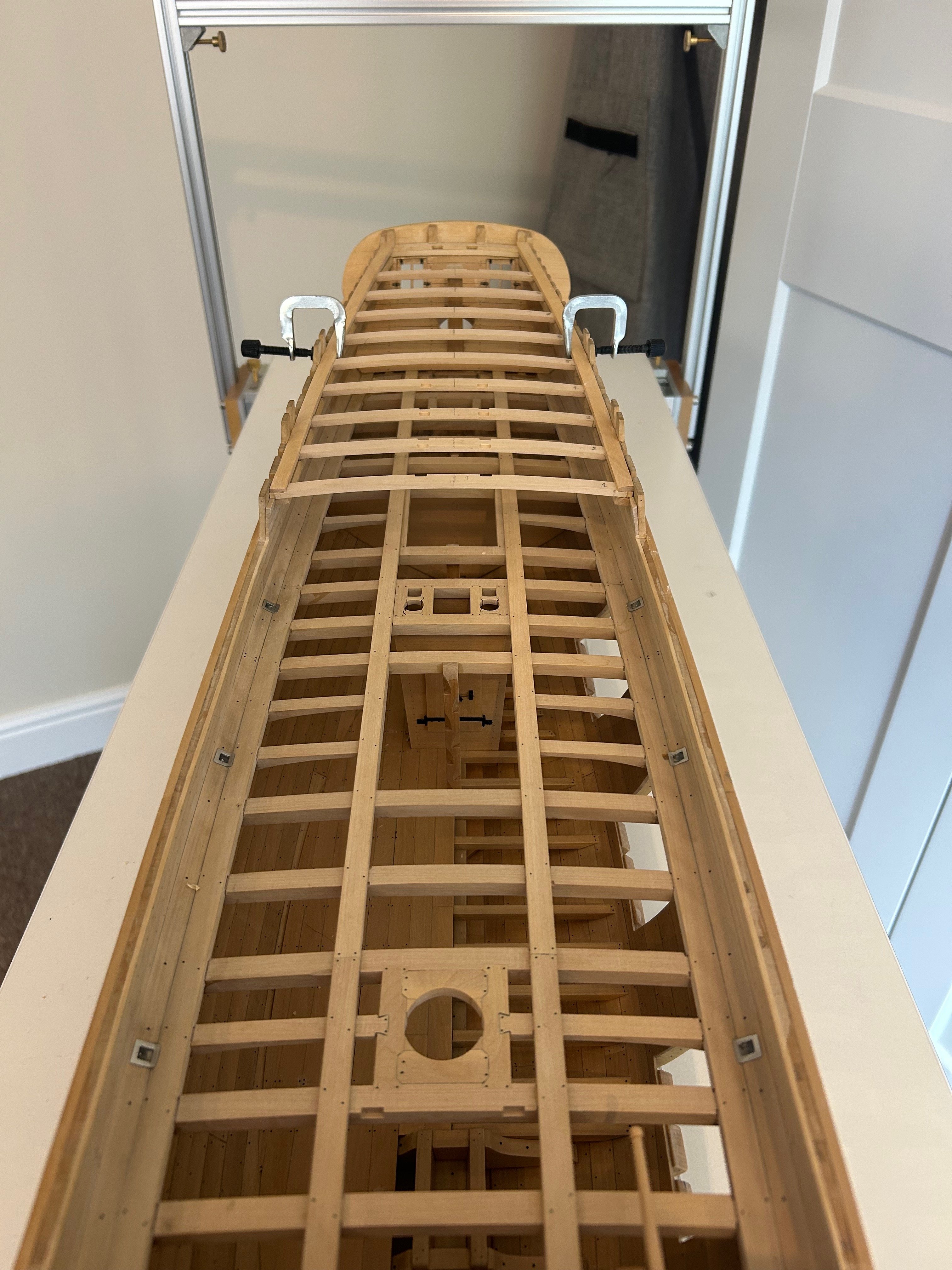
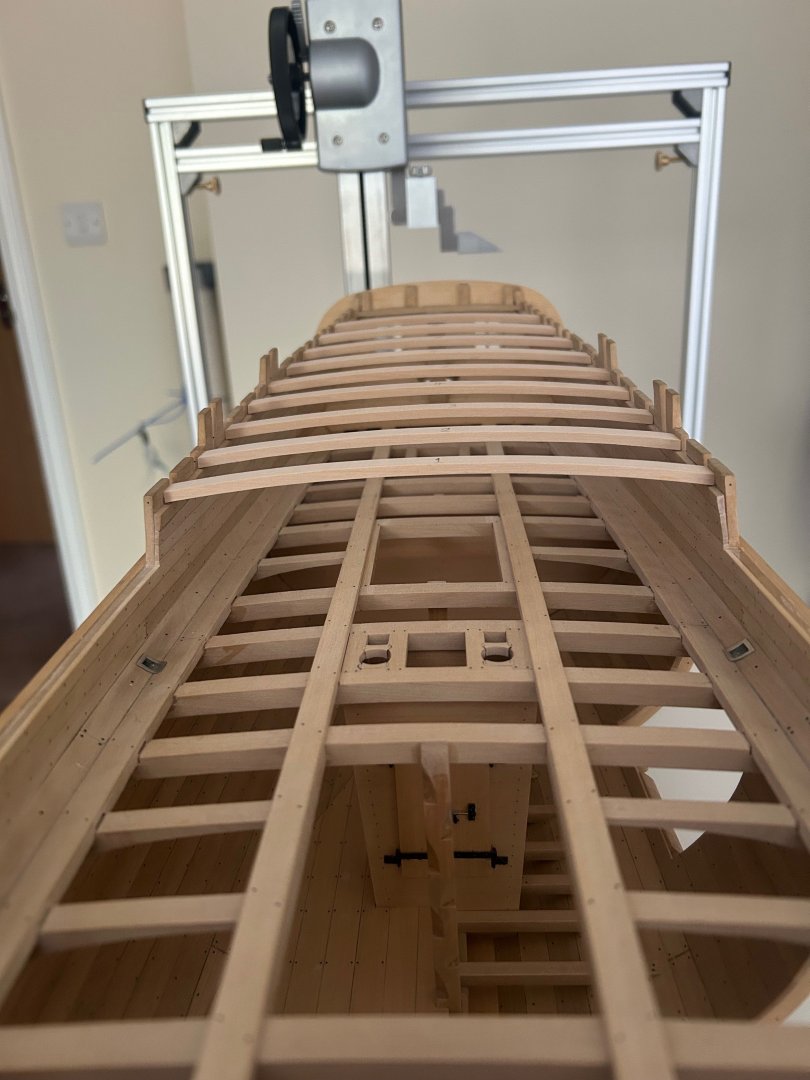
Hi Mike - it's a trick of the camera! The gantry is separate from the height gauge in front of the of it. This is the gauge that I use - I use this to measure so much as my datum for the build is the bottom of the keel. I didn't have this tool when I began building but I wish that I had.

-
druxey, dvm27 and SaltyScot - thanks for the comments! It's nice to know that it's not just me that has had to resolve earlier issues. After I built the quarter deck I was surprised just how much it changes the entire look of the ship. It just looks so much more complete and solid which was just another piece of encouragement to move forward. Mark
-
Thanks Jacques that really means a lot to me - Since starting Le Rochefort I have bought a few monographs which has made me appreciate just how good the monograph by Gerard really is. I also have to remember that this is my first POF build too! My shipyard is obviously on the sketchy side 🤣 but we get things done! Thanks Chris - We fly out next Sunday for a much needed 2 week holiday in the sun.
-
Hi Keith what a really nice comment - I also told Lorraine about your birthday wishes and she said thank you very much Cheers mate!
-
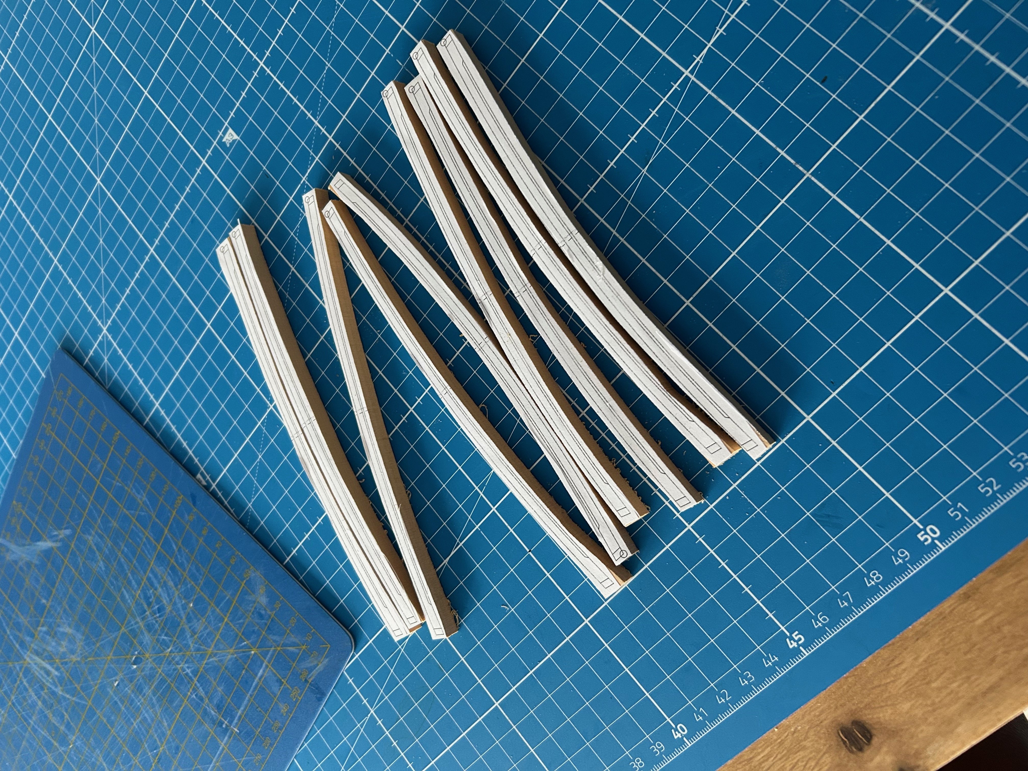
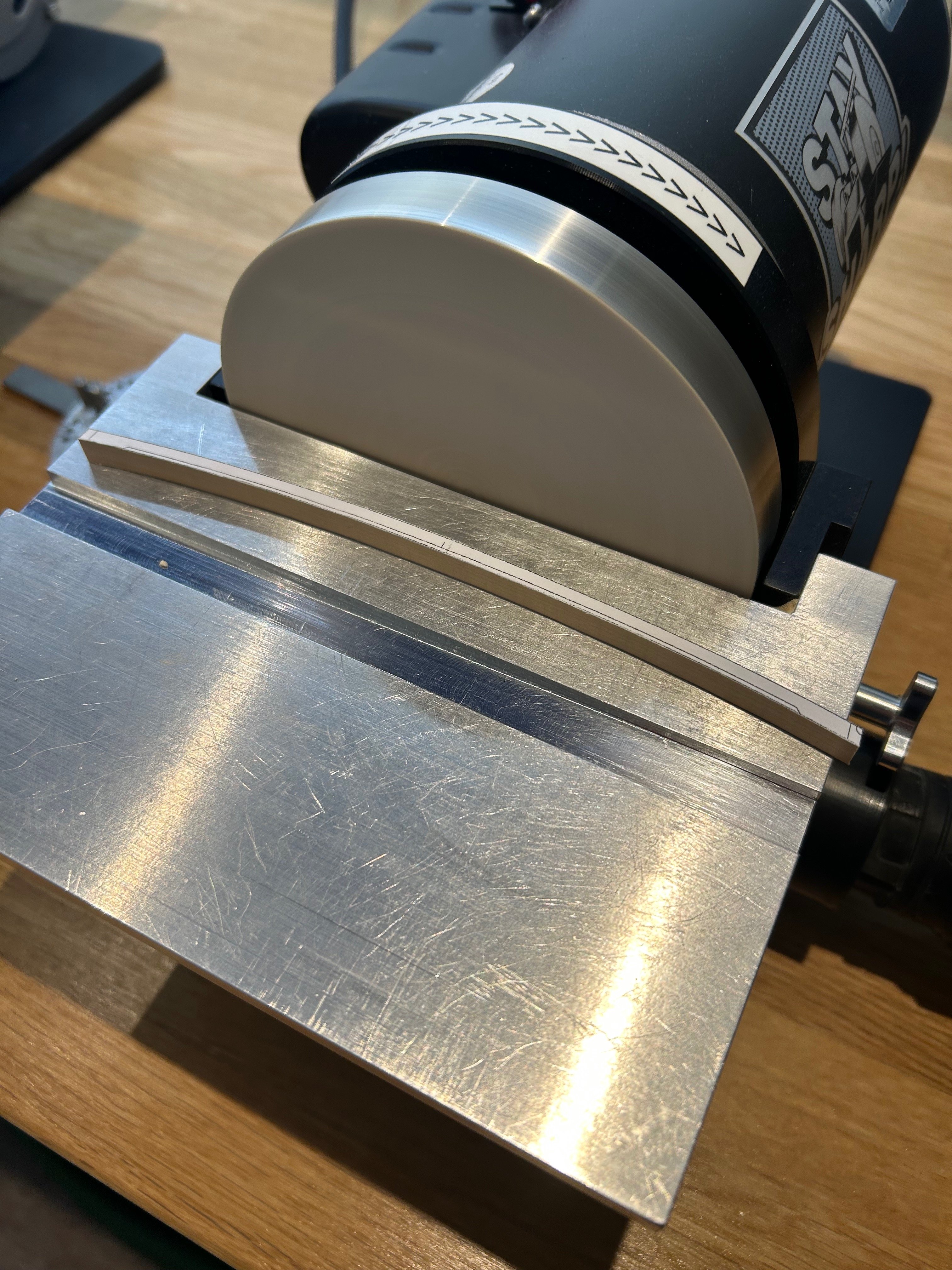
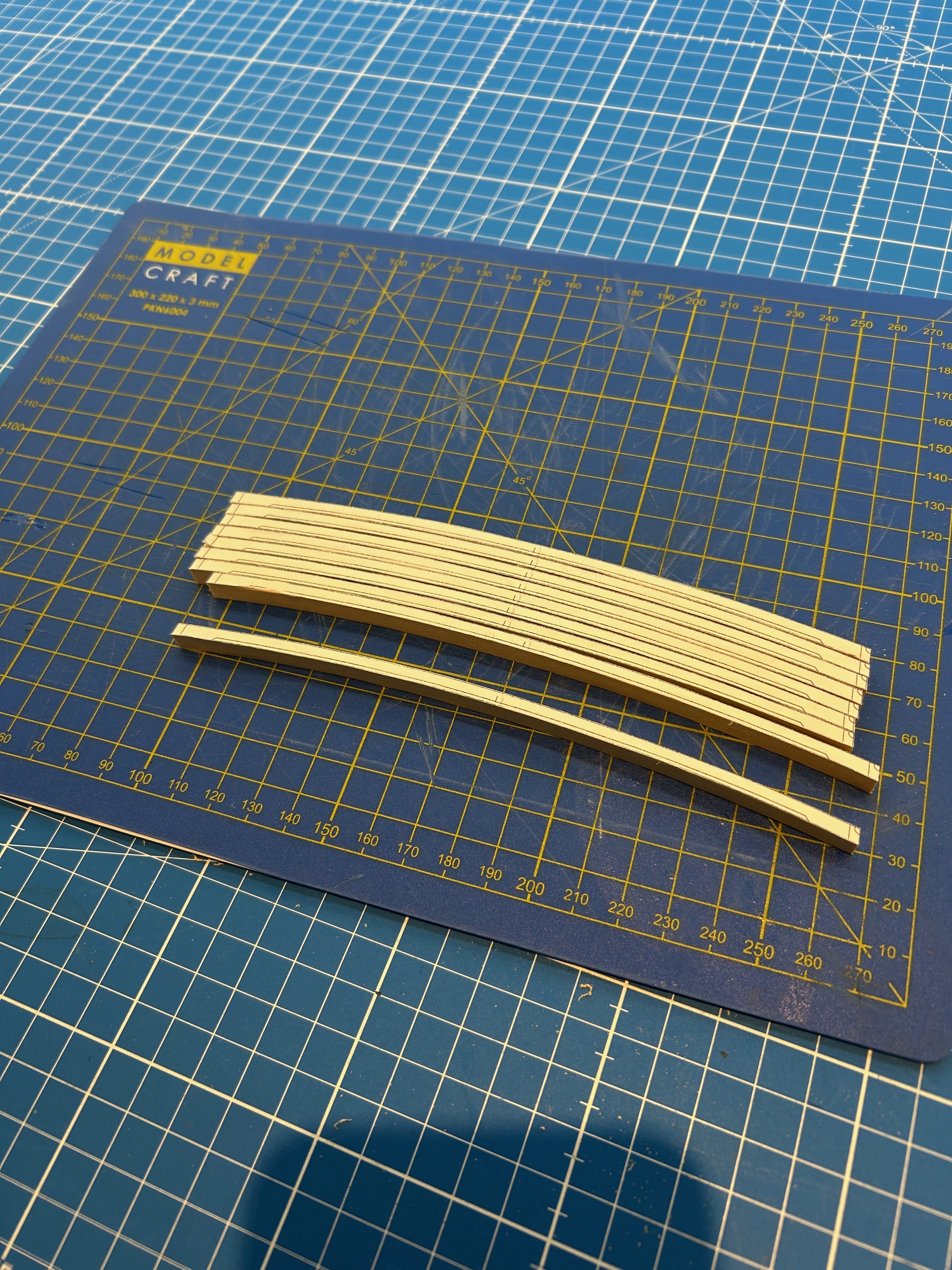
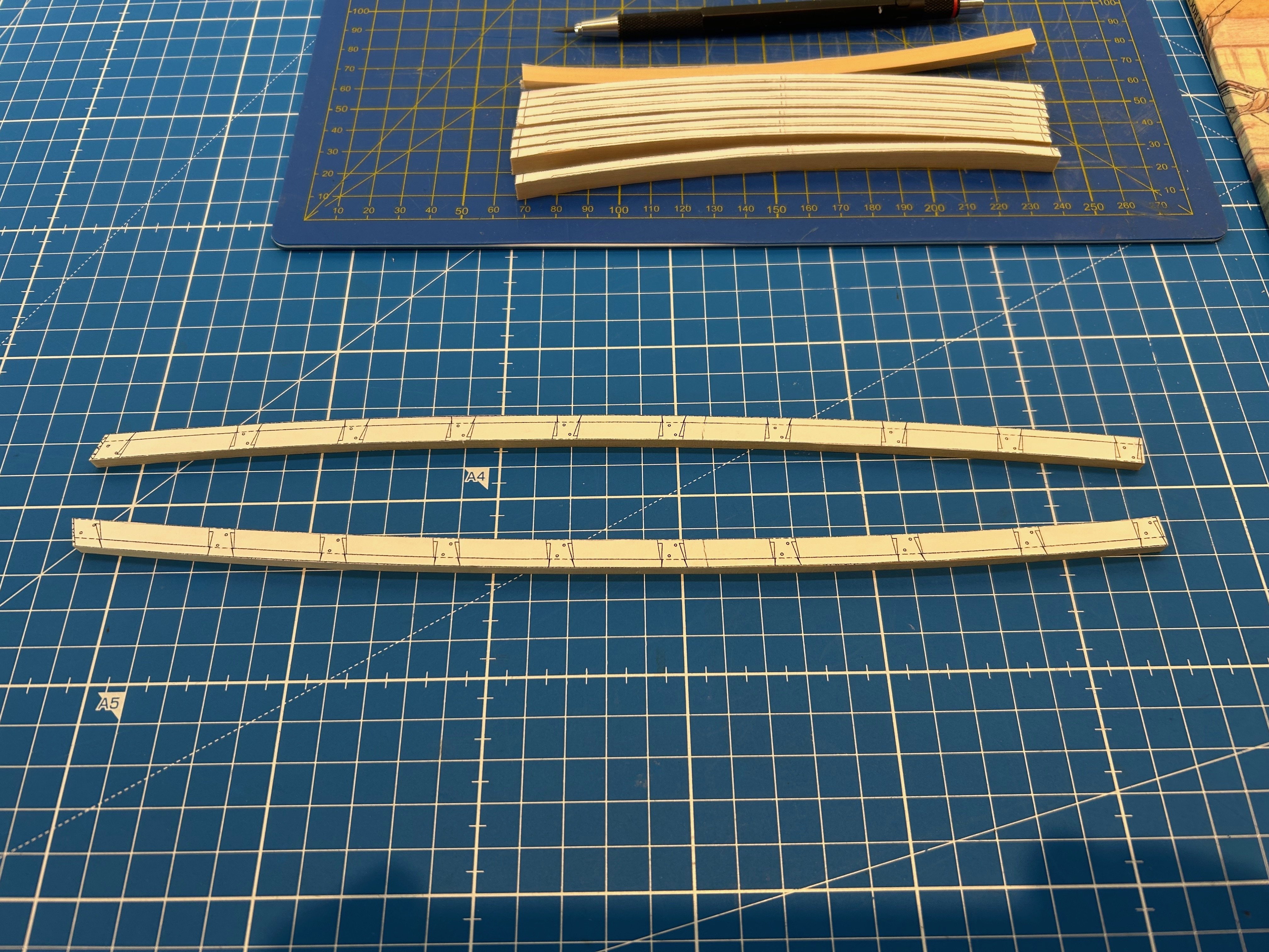
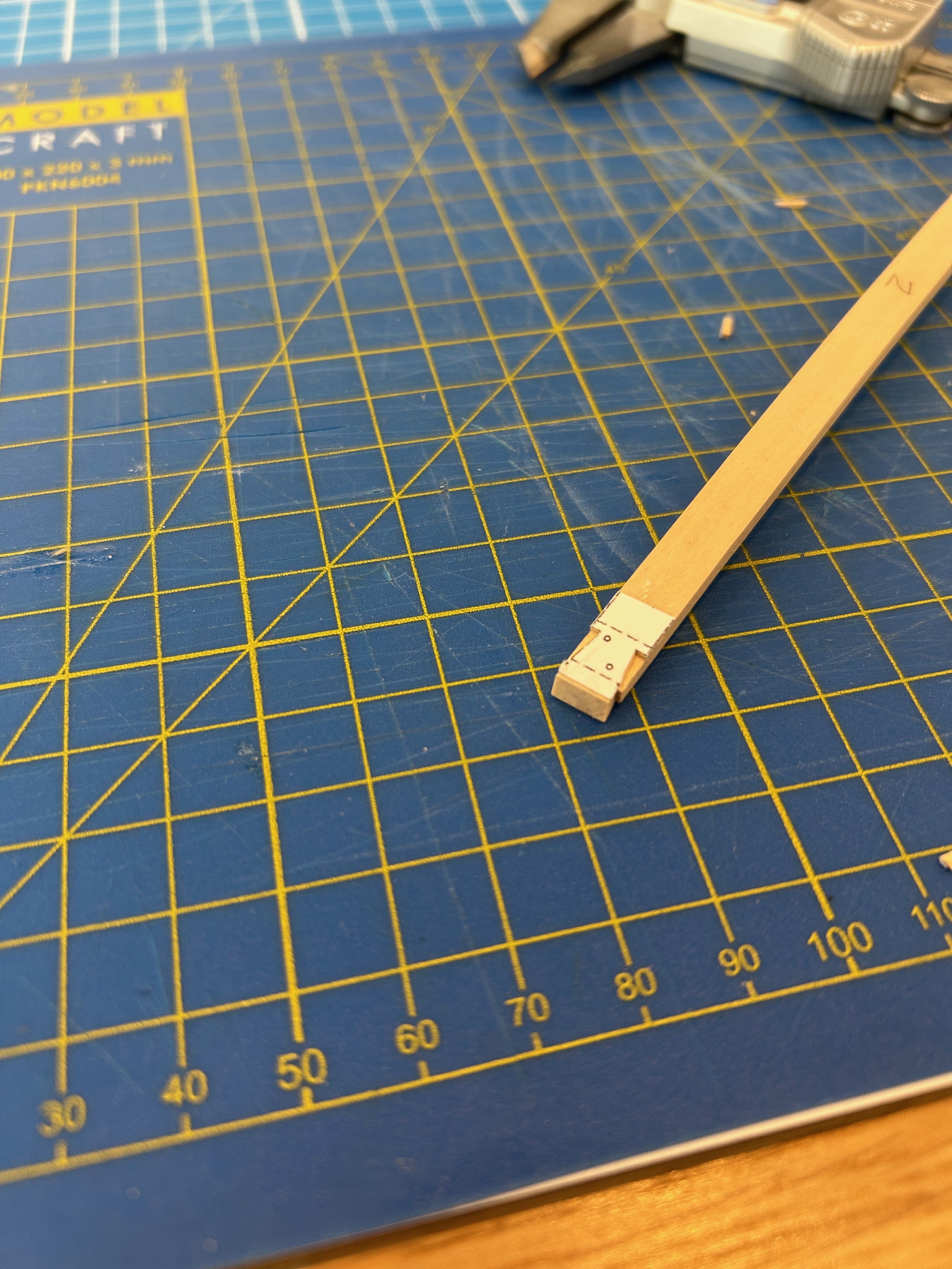
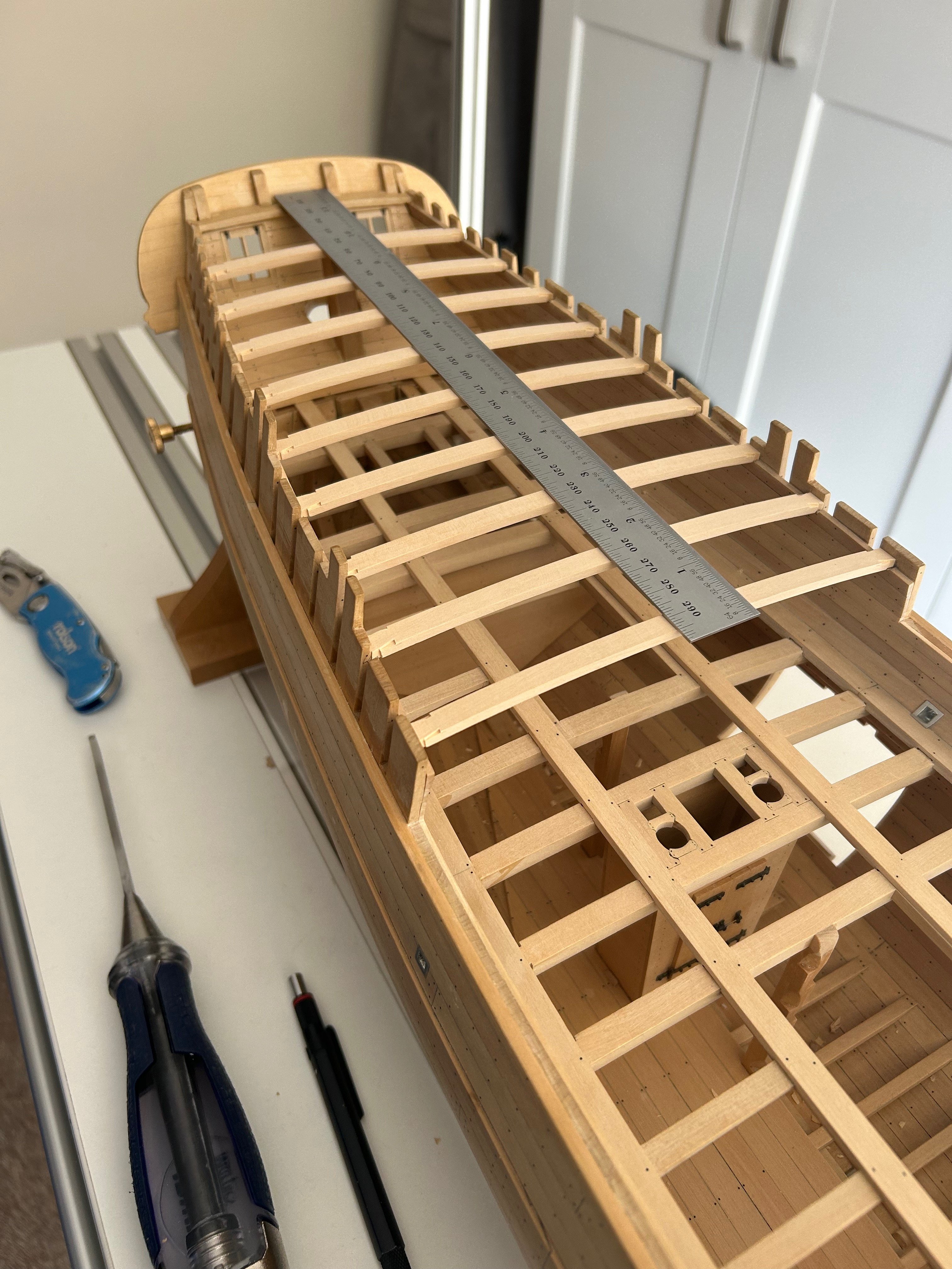
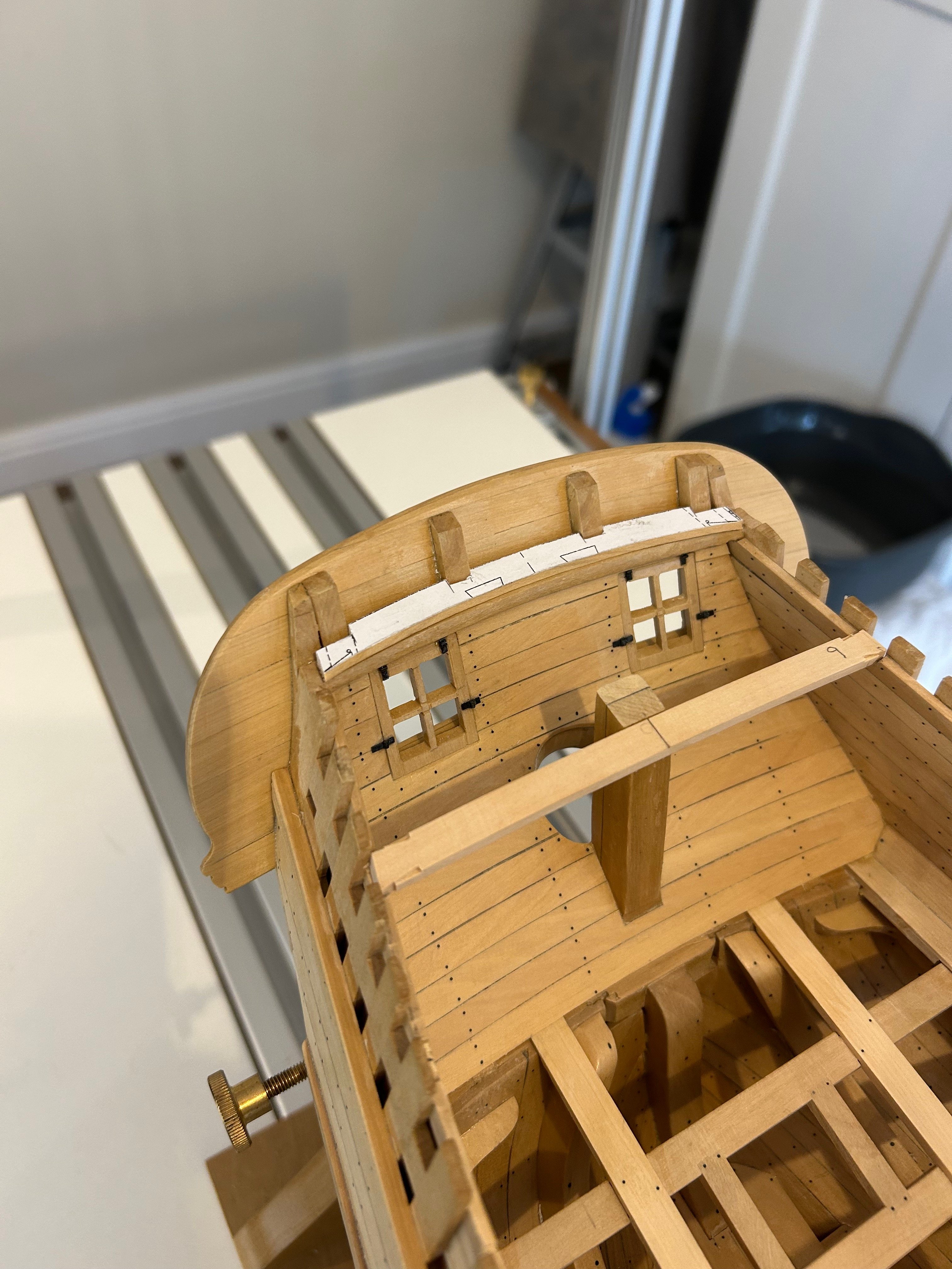
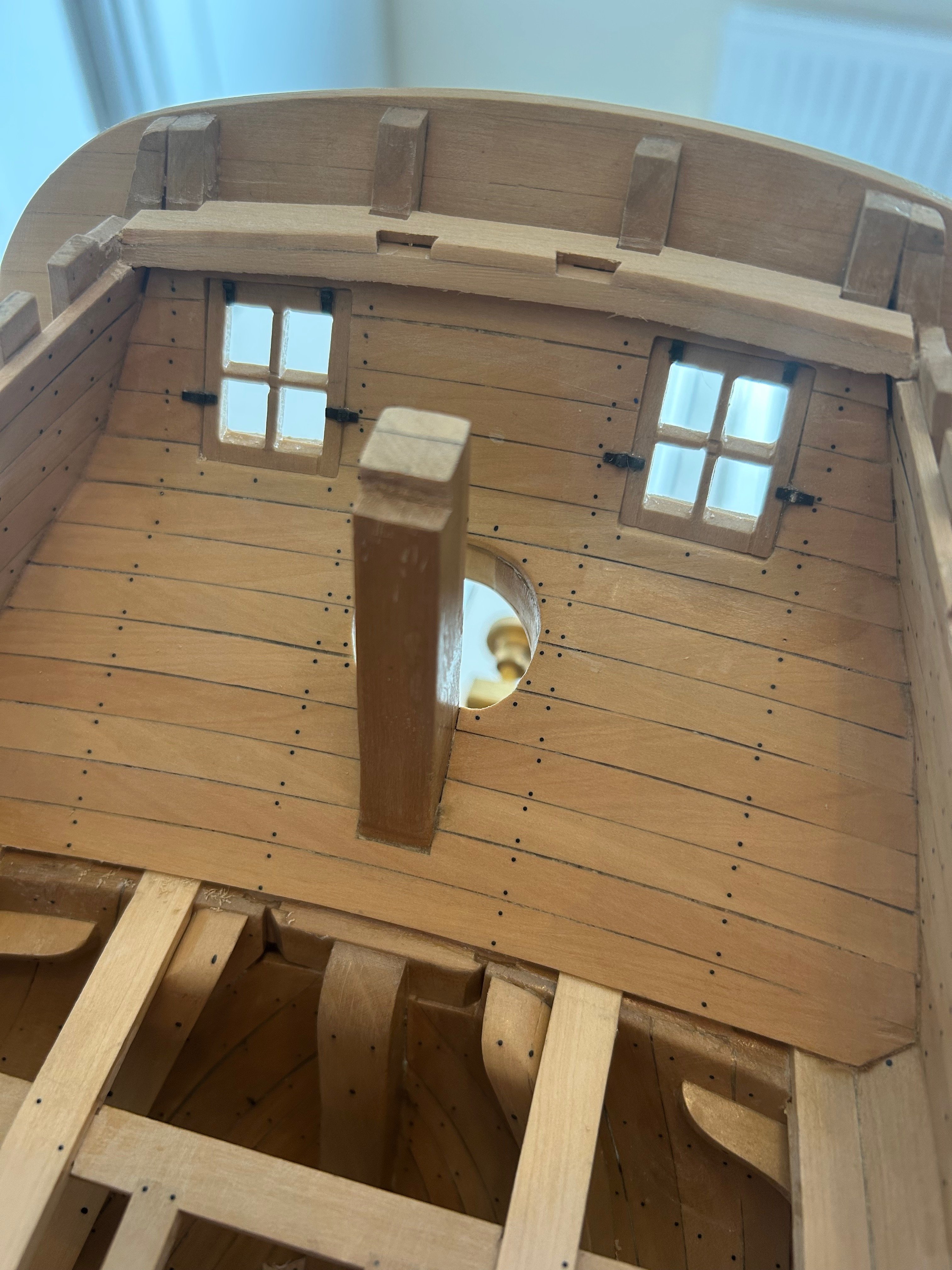
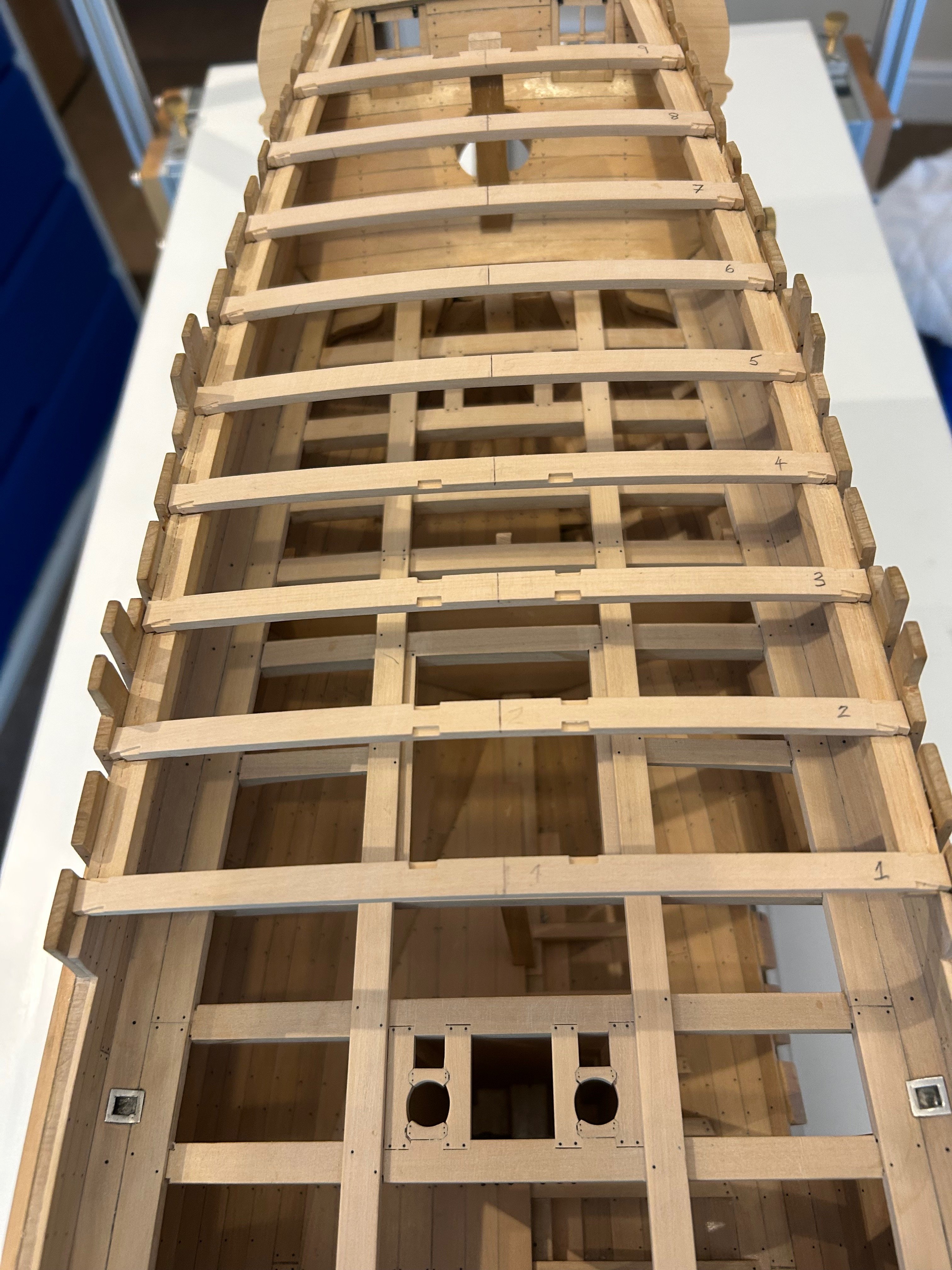
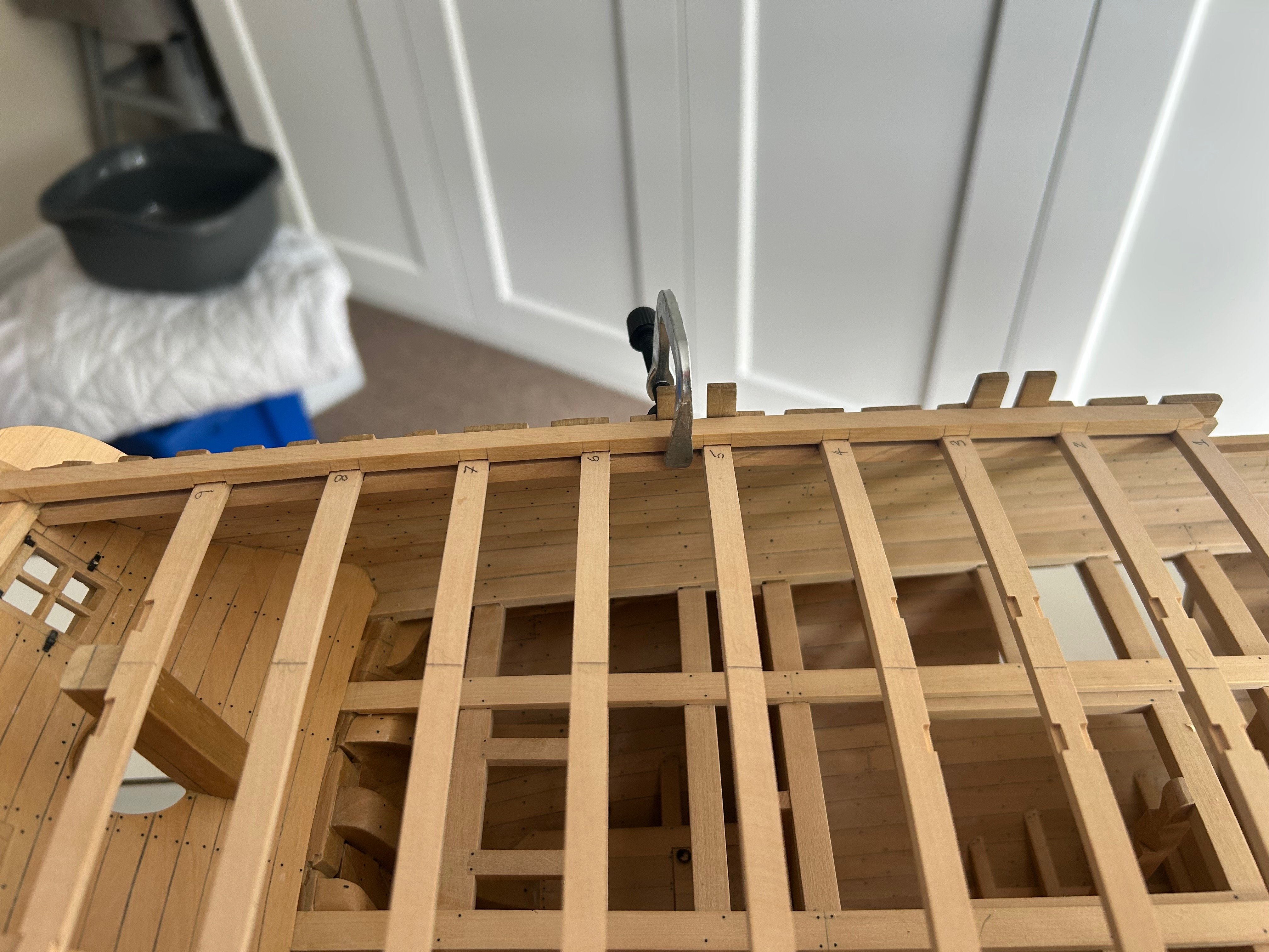
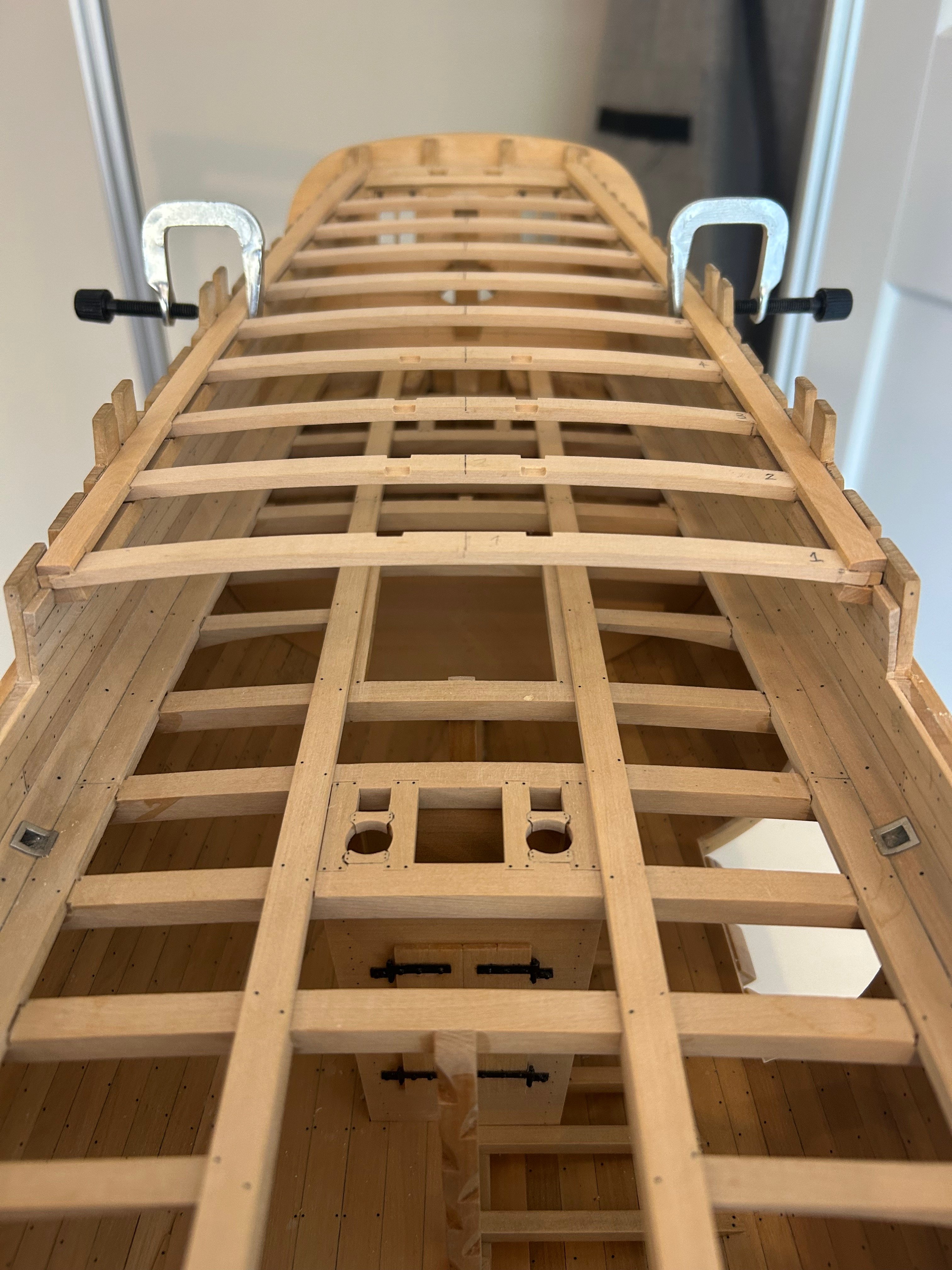
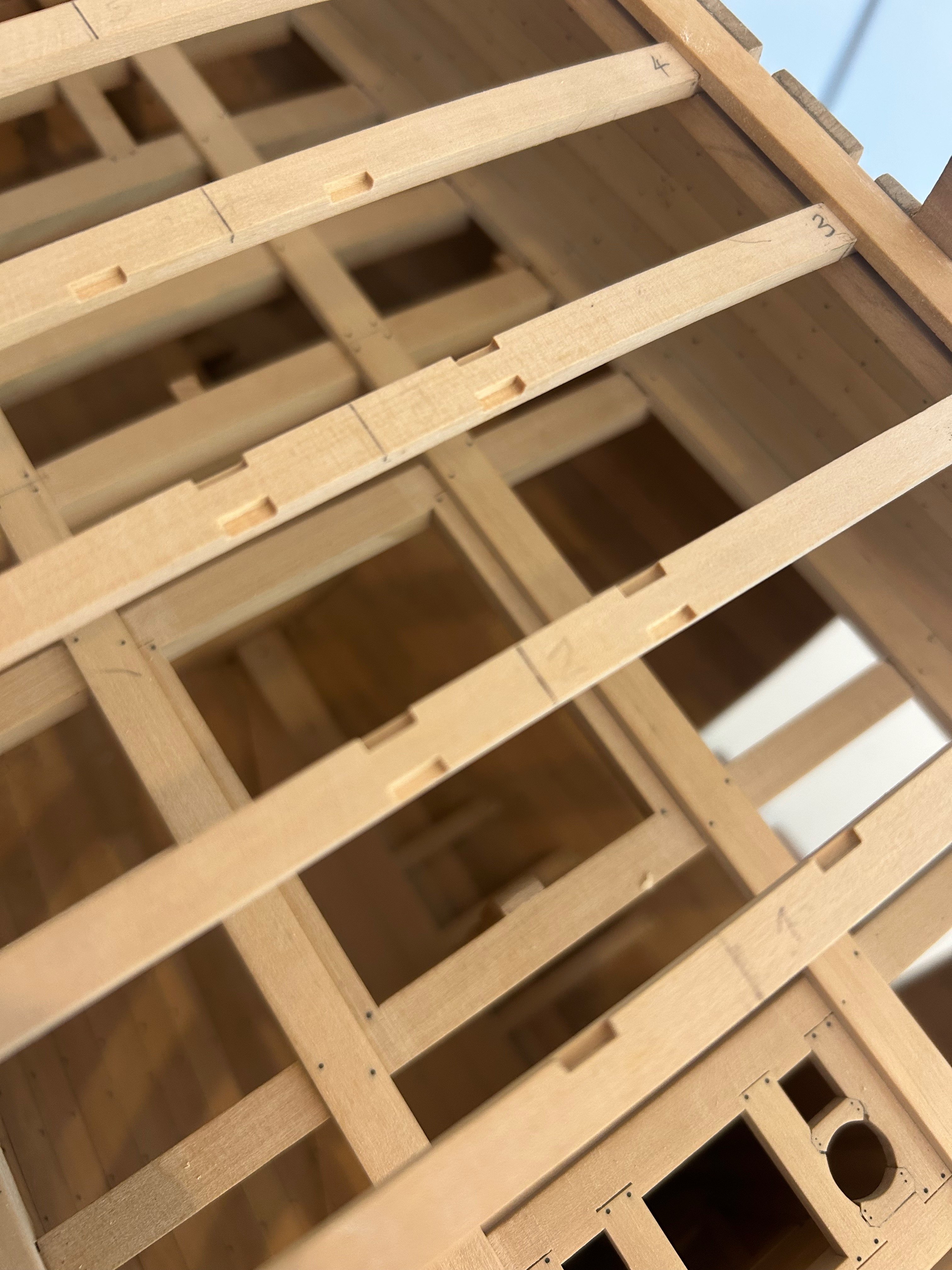
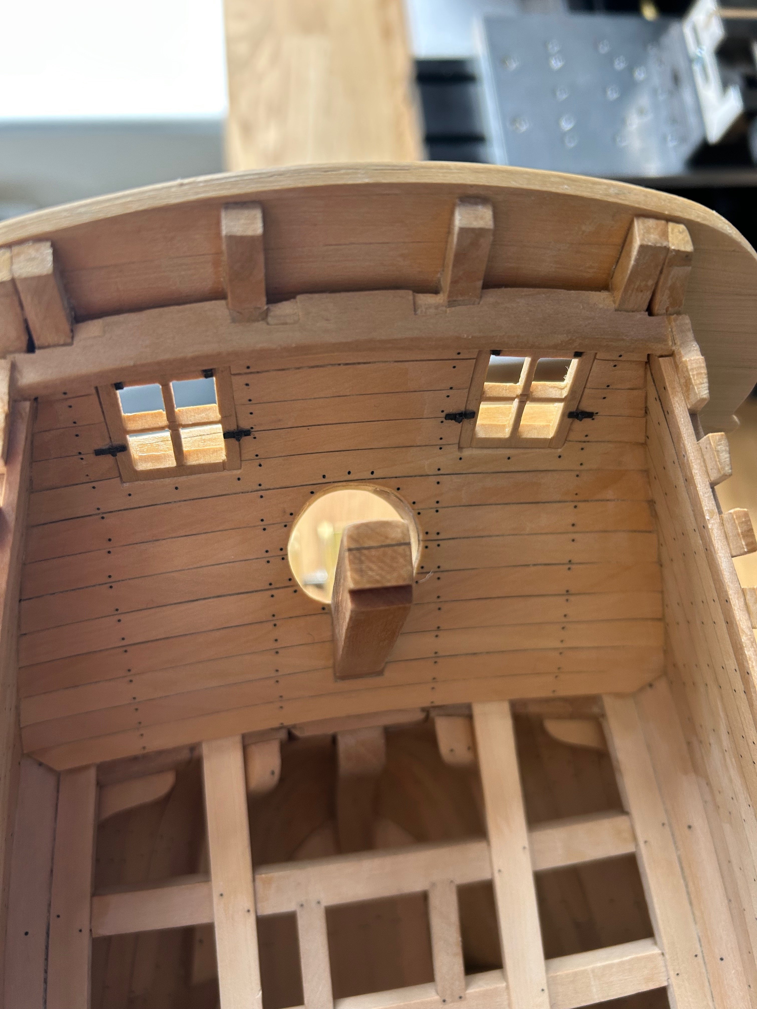
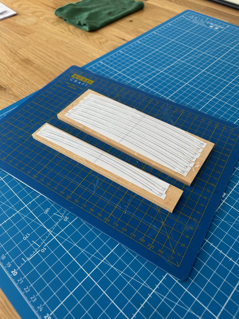
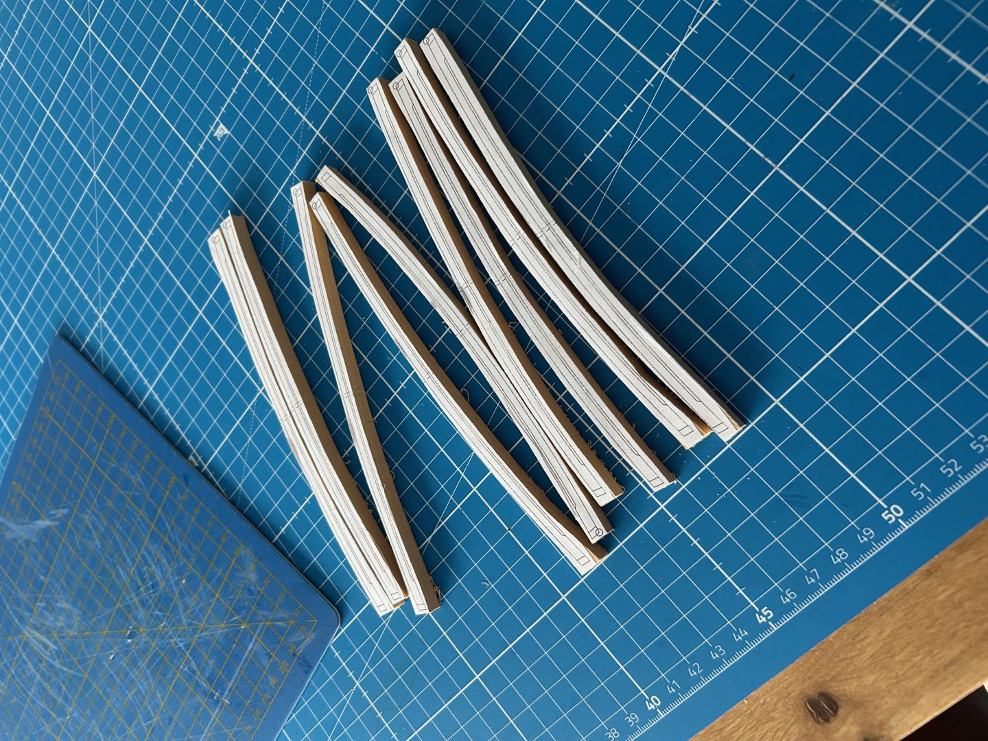
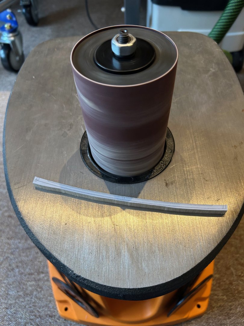
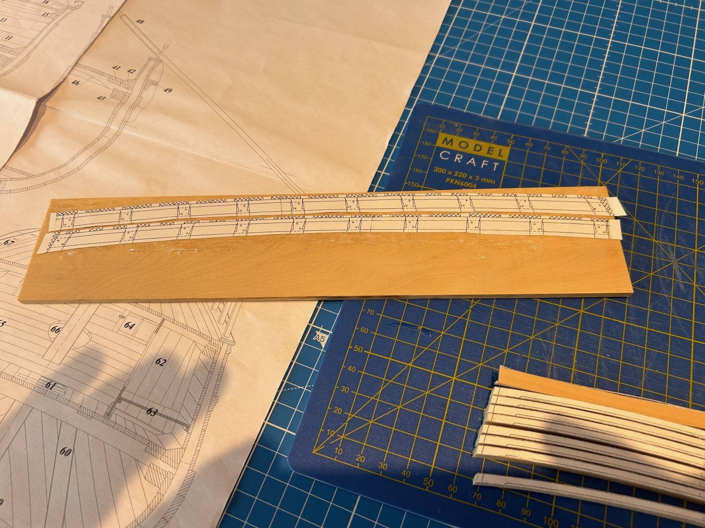
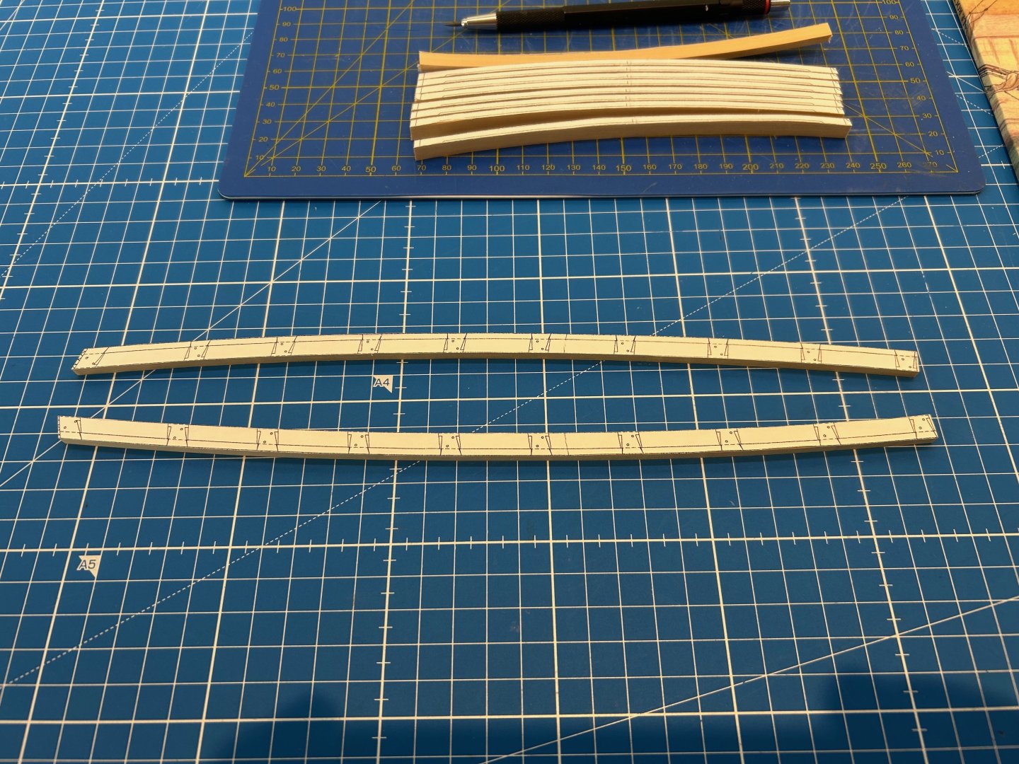
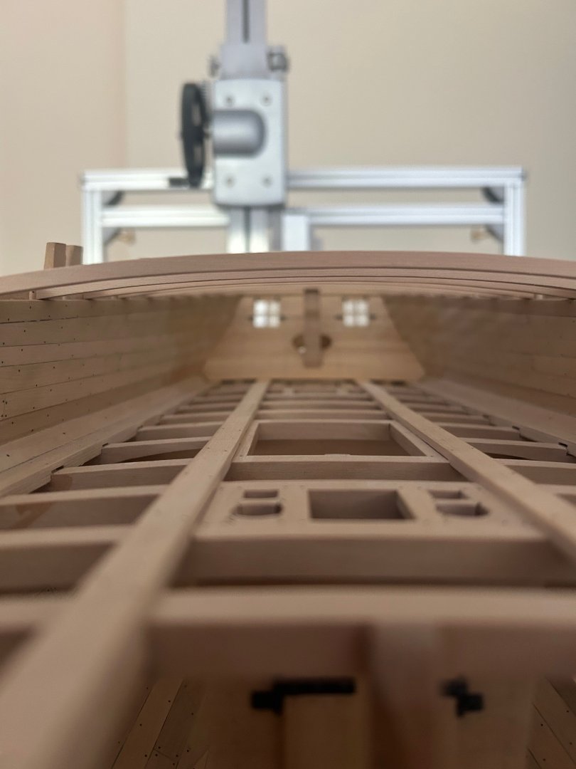
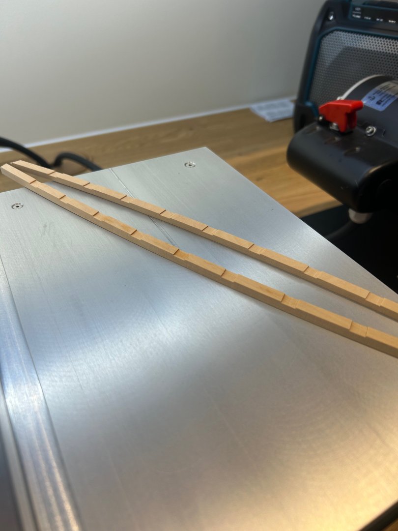
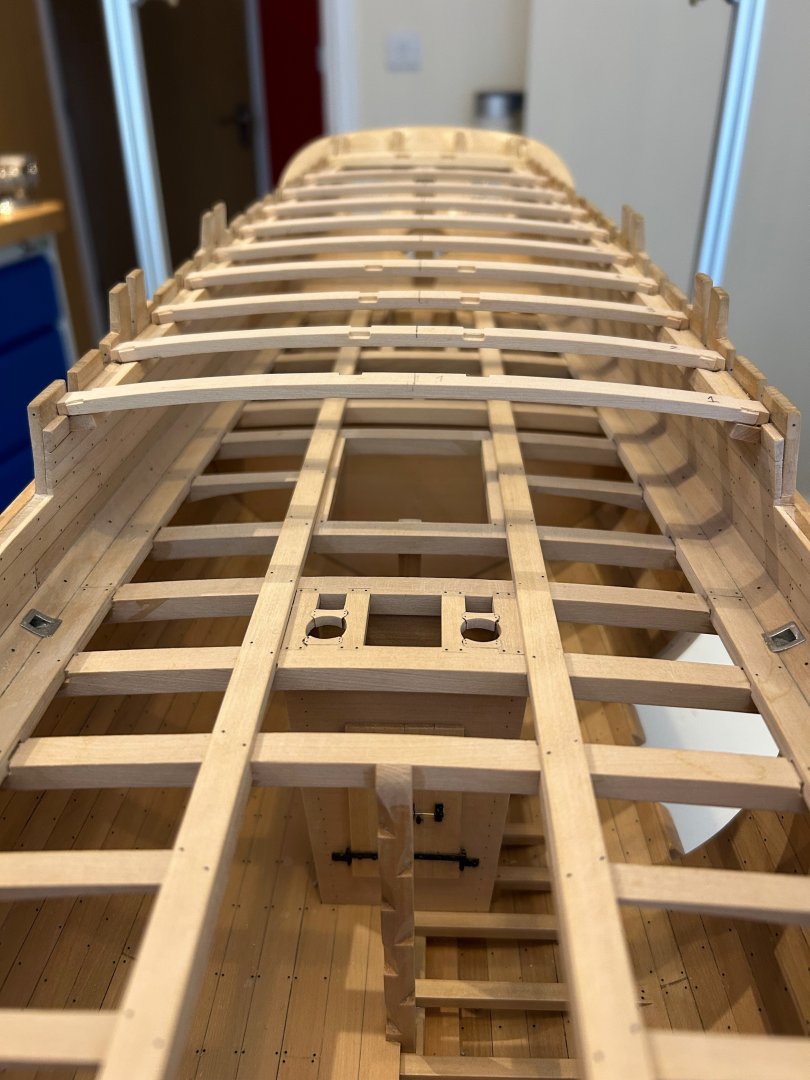
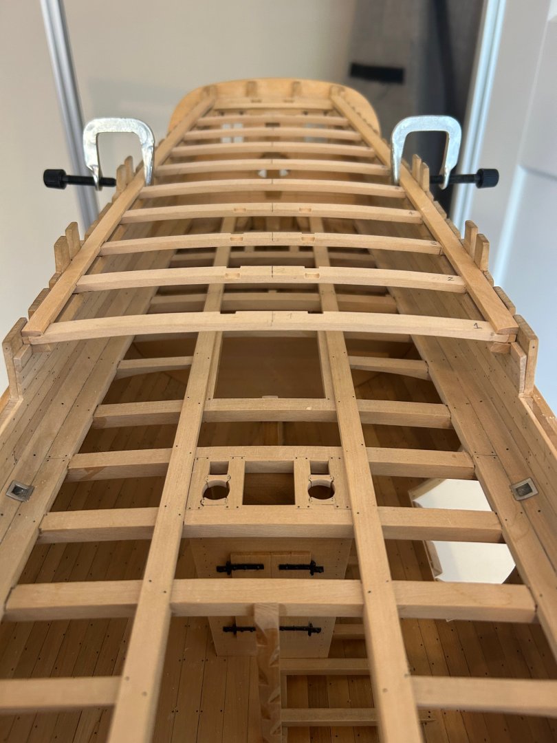
Hi All I've not posted in a while as I found an issue with my build that began 3 1/2 years ago when my building skills and general ship understanding were very much in their infancy I guess. I first noticed this problem when I fitted the stern timbers and stern windows. I could see that the counter timbers did not go fully to the top of the stern timbers and the quarter deck rear beam seemed far too close to the top of the windows. The issue is - I have set the counter timbers at the wrong angle which to correct at this stage would be very difficult indeed. I felt that this would be the end of the build as I have tried my very best to keep as accurately to the plans as possible. I decided just to have a break and come back to it later with a fresh outlook and see how I felt about the problem. So with a renewed outlook I took loads of measurements of the entire ship. I discovered that everything forward of the stern post is fine. I also discovered that everything rearward of the stern post is 5mm out of spec. So I have a ship that is 5mm longer than it should be and the issues that accompany it. Upwards and onwards - The build continues but first I had to address a couple of problems. I would need to lift the rear beam upwards to the correct height and the quarter deck would have to be bespoke behind the stern post. So firstly the rear beam - Rather than remove the beam I have just made it 1.5mm thicker by adding a piece on. Next I made the beams - here's a few pictures of the process that I use. Just rough cut on the band saw I prefer to sand the inner curve first but I'm sure it makes no difference Then the outer Next I cut the dovetail joints - I really like doing this part its so satisfying Then I cut them into the clamps using a height gauge to make sure that they are at the correct height. I also sense check the alignment with a steel rule as they must be level with the stern post. Then I made the beam supports Finally I made the waterways which sit nicely on the level of the planksheer So although I'm not exactly to the plans anymore I think I've pulled it back enough to get away with it. I do have knock on issues such as the taff rail will be longer etc etc.... but I've got my head around what needs to be done. On the positive side you are getting 5mm more ship for your buck!!! Also stepping away sometimes is a very good thing to do! I'm very much back into it now - A slight delay though as it's my wife's 60th birthday next week so we are off to Crete for a fortnight to celebrate. I can now remove all of the beams and start some of the interior detail. Mark


-
HMS ANSON 1781 by albert - 1/48 - 64 guns
No Idea replied to albert's topic in - Build logs for subjects built 1751 - 1800
Albert your work is simply amazing and very inspiring too -
pin vise and drill bits
No Idea replied to palmerit's topic in Modeling tools and Workshop Equipment
Just my experience but I have tried different types of pin vices and found some to be lacking for my needs. The clamping action in many is just so poor that it makes the whole job so much harder. I settled on the Starrett and they have now given me years of trouble free work so I would recommend these. As for the bits I only buy cobalt bits now - they are strong and stay sharp for ages. They will also plow through brass and stainless steel without any problems. -
L'Amarante by marsalv - 1:36 - POF
No Idea replied to marsalv's topic in - Build logs for subjects built 1501 - 1750
Beautiful work the bits could be a stand alone model. I've been watching some tutorials on Vcarve and at some point may take the plunge on trying to learn it better. I was wondering how you take the drawings and transpose them into Vcarve? I'm a total novice with Vcarve and CNC so I expect your answer will give me more questions than answers. -
Fractal vise on kickstarter
No Idea replied to DavidG's topic in Modeling tools and Workshop Equipment
I really like things like this especially kickstarter projects. I think its got very good potential and fixing it to a mill would be a simple conversion or simply clamping it down. I've decided to back this project so I'll let you know in about 9 months whether it's come to fruition or not so thanks for sharing the project. -
L'Amarante by marsalv - 1:36 - POF
No Idea replied to marsalv's topic in - Build logs for subjects built 1501 - 1750
Thats just genius!! -
Fractal vise on kickstarter
No Idea replied to DavidG's topic in Modeling tools and Workshop Equipment
David do you have a link to this vice? -
Wow congratulations on such a nice build - not only do you have carpentry skills but CAD skill too. Lovely job 👍
-
Now that is a Pegasus!! A fitting figurehead for such an amazing ship - good luck with the carving I'm sure it will be fantastic 👍
-
Fantastic website Chris - easy to navigate and the ships look amazing. I don't know how you make such lovely models for the price - they are a bargain for the result that builders get!
-
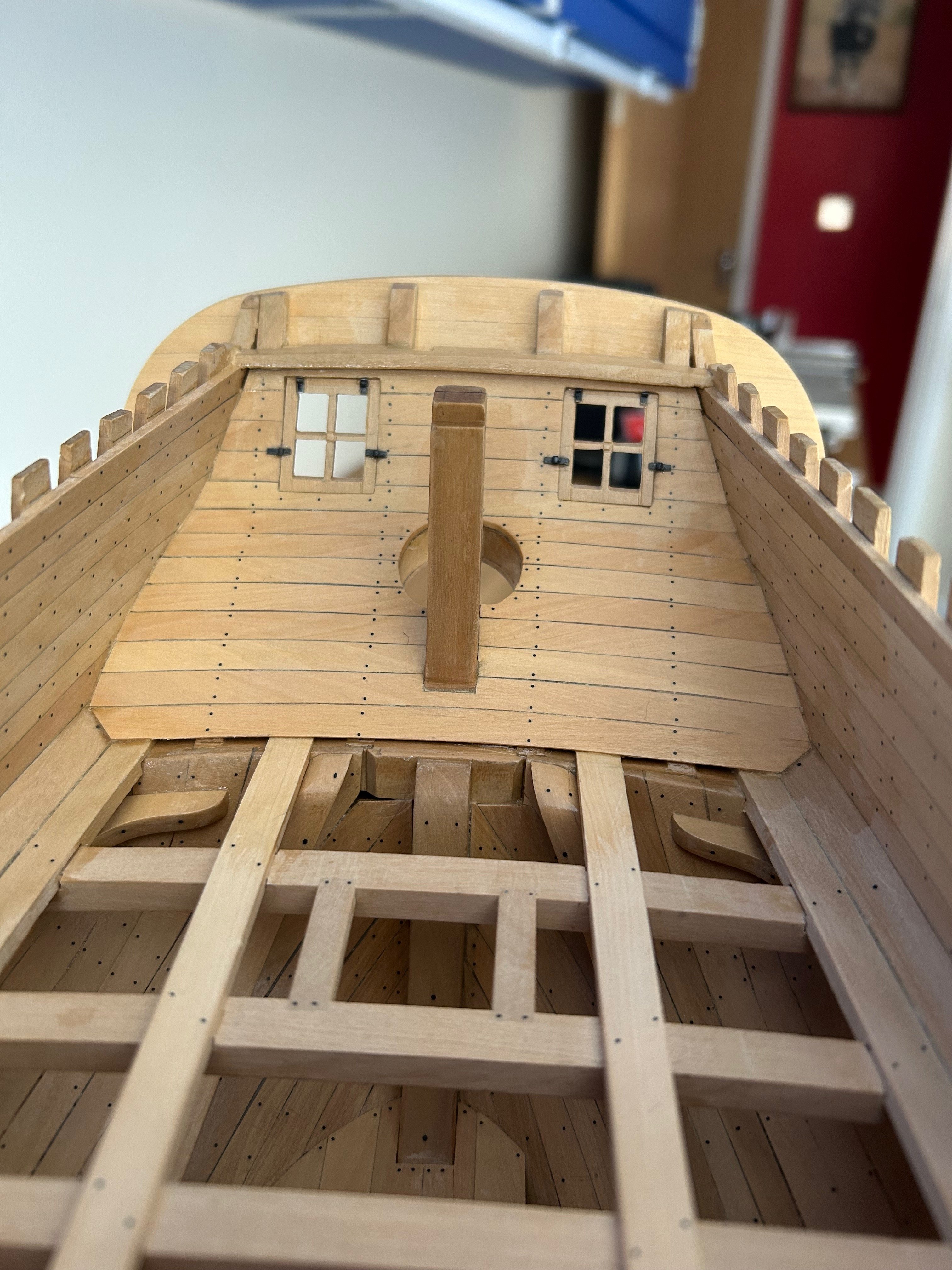
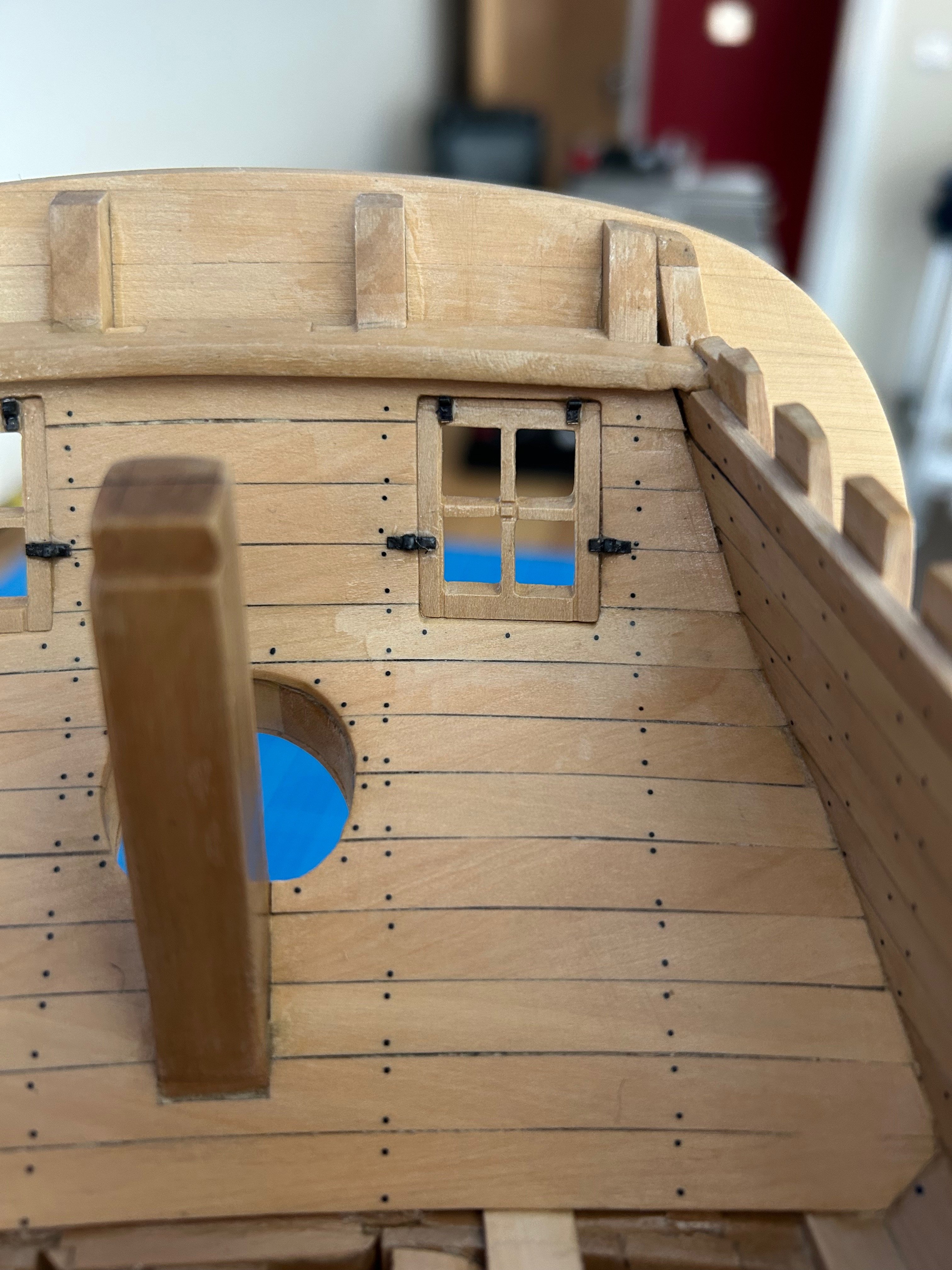
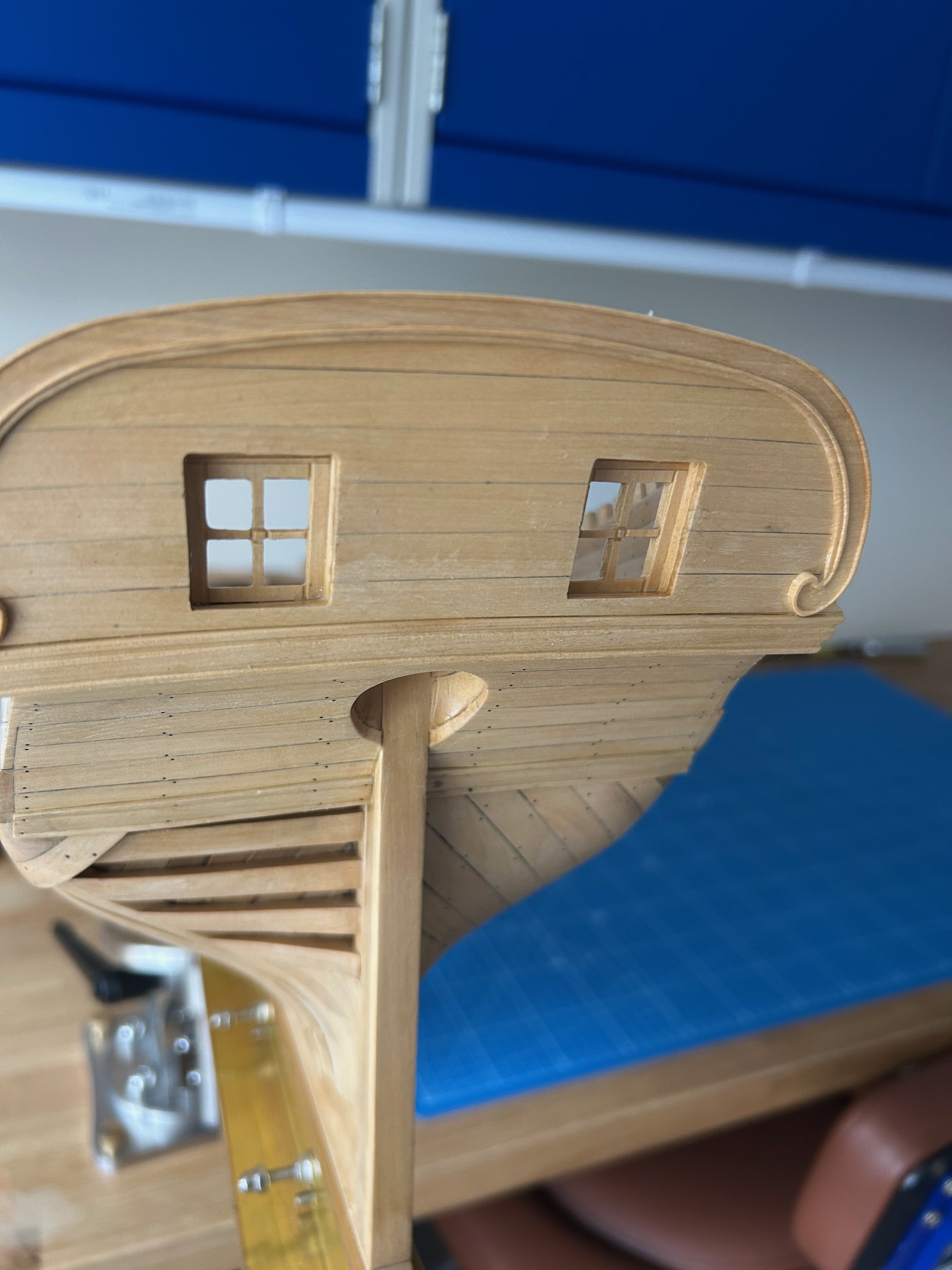
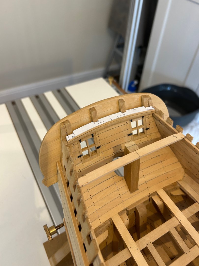
Another update from me - I've now closed off the stern and finished the stern windows. There's not too much to say about this work other than the planking is not straight but curved. I tried bending planks but pretty much got no where with that so in the end I made them from a 13mm wide plank by sanding them to shape. The hinges and closers are blackened brass. I still need to place the nails on the external planks but thats a nice easy job. I think I'm going to make the quarterdeck beams, supports and waterways next. Mark


-
L'Amarante by marsalv - 1:36 - POF
No Idea replied to marsalv's topic in - Build logs for subjects built 1501 - 1750
Fantastic work! When I had a go at Samson posts I thought about using a mill. But actually I found them really nice to make just using a chisel. Maybe I'll try a mill next time as your results are lovely. -
The last plank I have found takes the longest to trim but is the easiest to fit. The very last plank I always trim to be an interference fit so that it is tight to get in place. This just takes time and patience and because it's a tight fit I usually use a very small hammer with plastic ends to get it into place. I've never used clamps on the last plank
-
Fantastic 👍👍👍
-
Question re "Line Off"
No Idea replied to JohnWW's topic in Building, Framing, Planking and plating a ships hull and deck
This is a fantastic observation and you are absolutely correct. Thinking back I used narrower planks on my first planking compared to the second layer. That way the overlap of any seams was minimal 👍 -
Sherline Mill Ring Light
No Idea replied to No Idea's topic in Modeling tools and Workshop Equipment
Hi Ian this could easily be made from hardwood and the hole made using a hole cutter. Good luck with your project 👍