No Idea
-
Posts
1,036 -
Joined
-
Last visited
Content Type
Profiles
Forums
Gallery
Events
Everything posted by No Idea
-
 GrandpaPhil your ship is looking incredible - amazing work
- 179 replies
-
- 4
-

-

-
- Card
- Pre-Dreadnought
- (and 2 more)
-
Planking and Beveling
No Idea replied to Alfred A's topic in Building, Framing, Planking and plating a ships hull and deck
Hi Alfred this is a really good question 👍 Planks are bevelled so that they contact their respective planks on each side tightly. If you put a plank onto a hull just get a square edged plank and butt it up against the one that is fitted. You will see that due to the curvature of the frames they will not meet tightly there will be a gap as they do not meet at 90 degrees. So bevelling is the art of making them meet correctly and the bevel does change as the strake goes from stem to stern. In practice though you will only need to be roughly right. I only bevel one edge but I may be the odd one out here. So working from the garboard plank upwards I would bevel the plank that meets it and leave the other edge square. I would then bevel the edge on the next plank that meets that one and so on. The very last strake of planks will have bevels on both sides. Also I always make the last strake of planks somewhere near the middle of the ship. So I start planks from the garboard upwards and also from the whale downwards and then meet in the middle. I hope this helps - Mark -
A very brave decision - I did exactly the same as you and have not regretted it
-
Just a heads up- there is a table saw and thickness sander for sale in the UK. Nothing to do with me but I thought I’d let you all know
-
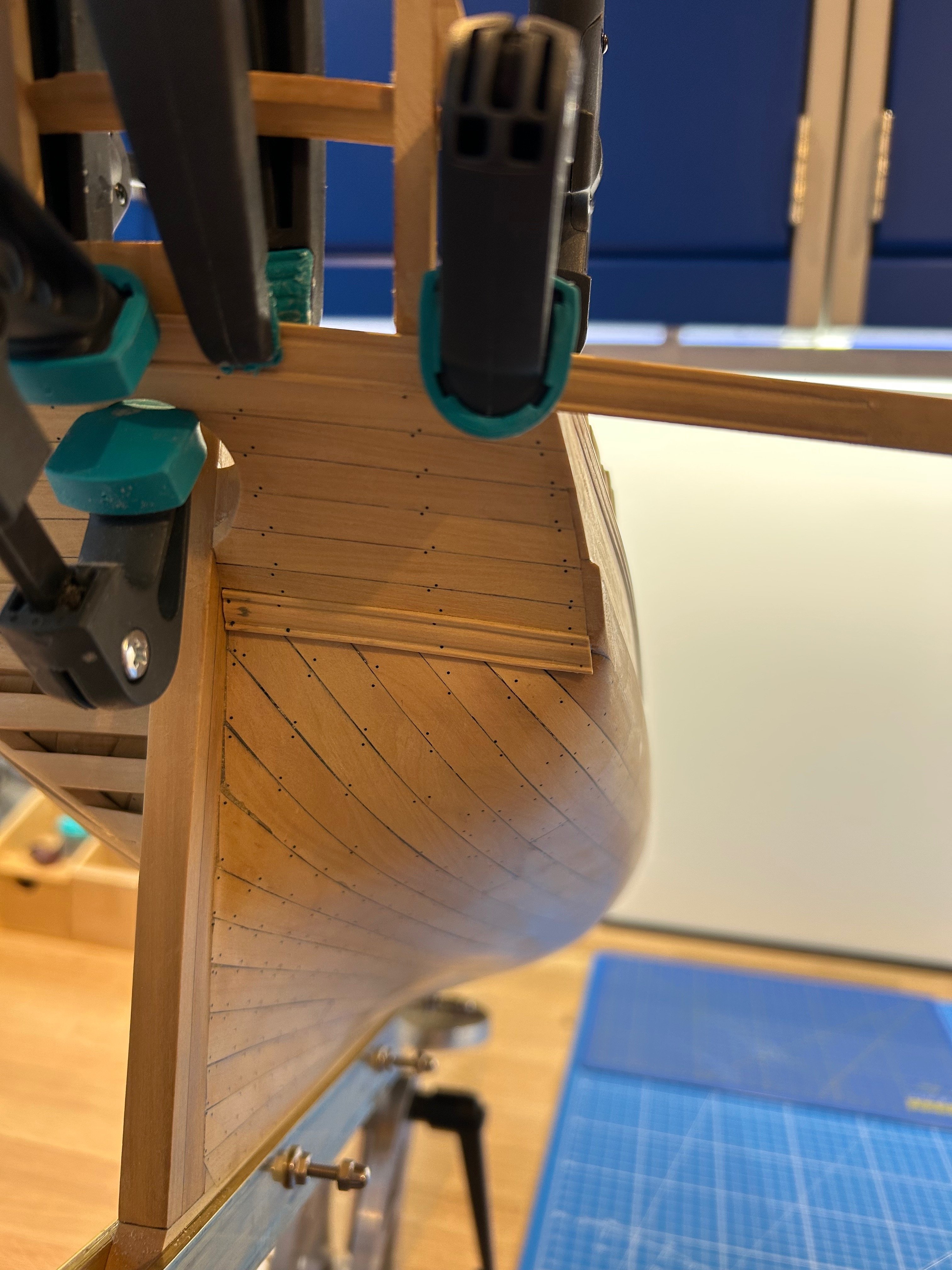
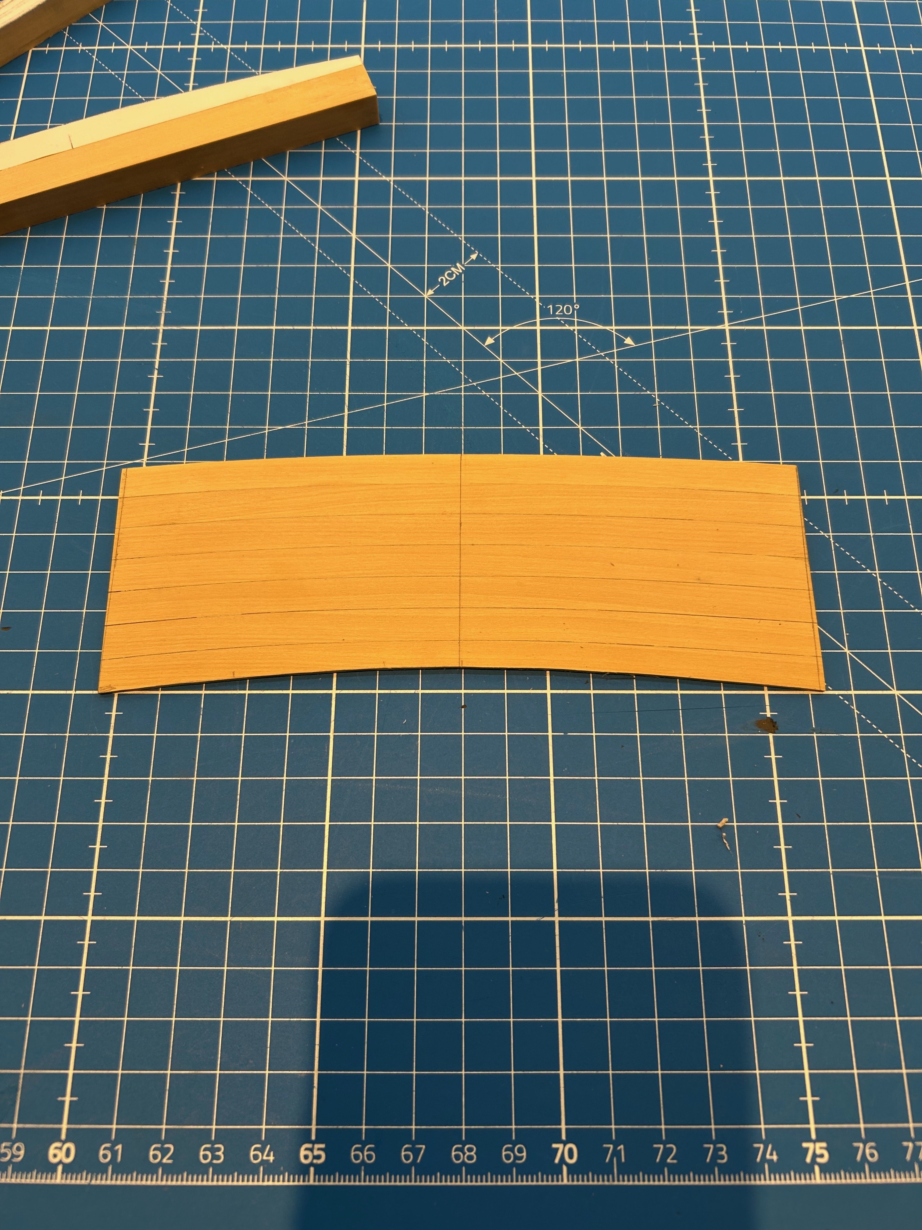
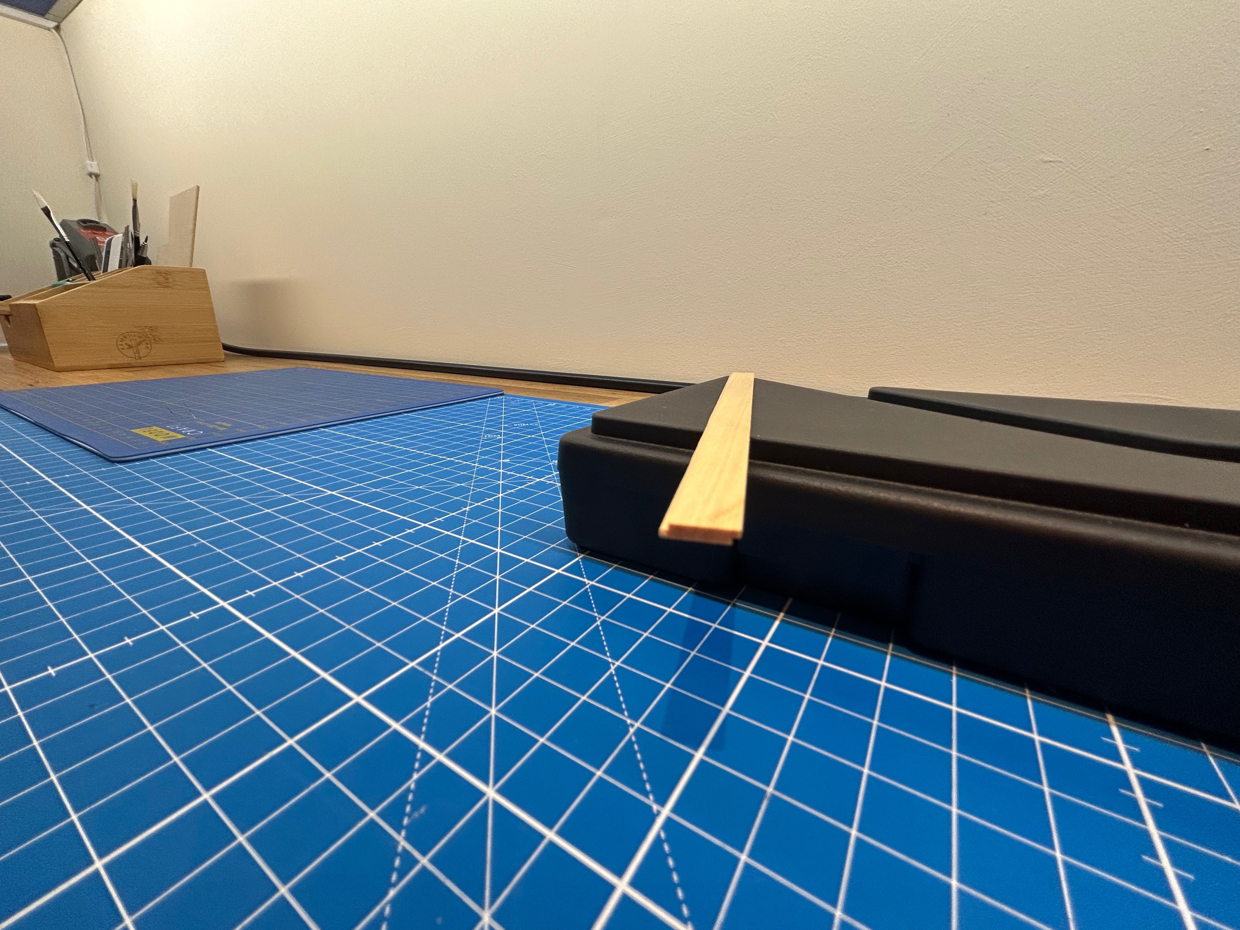
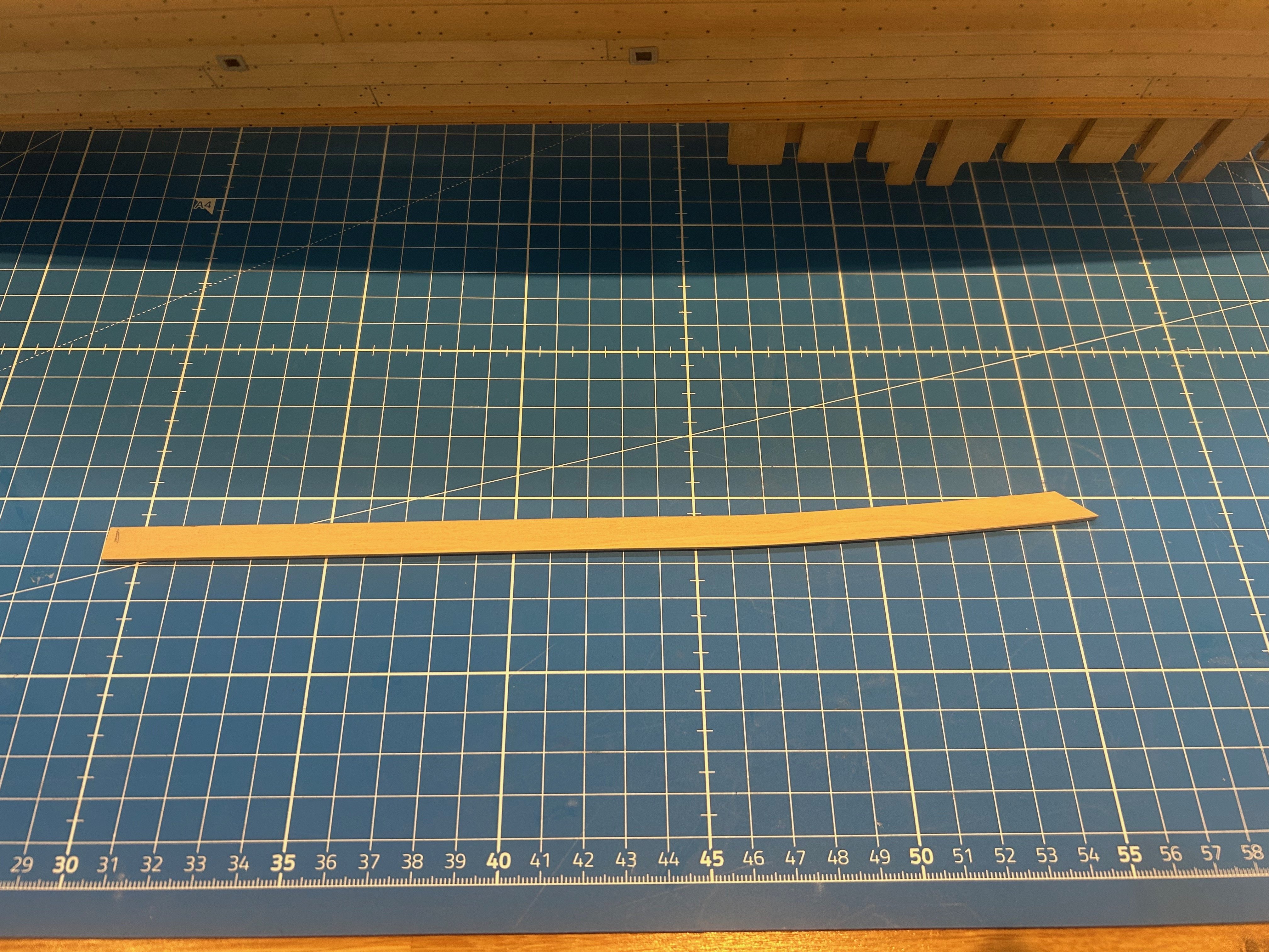
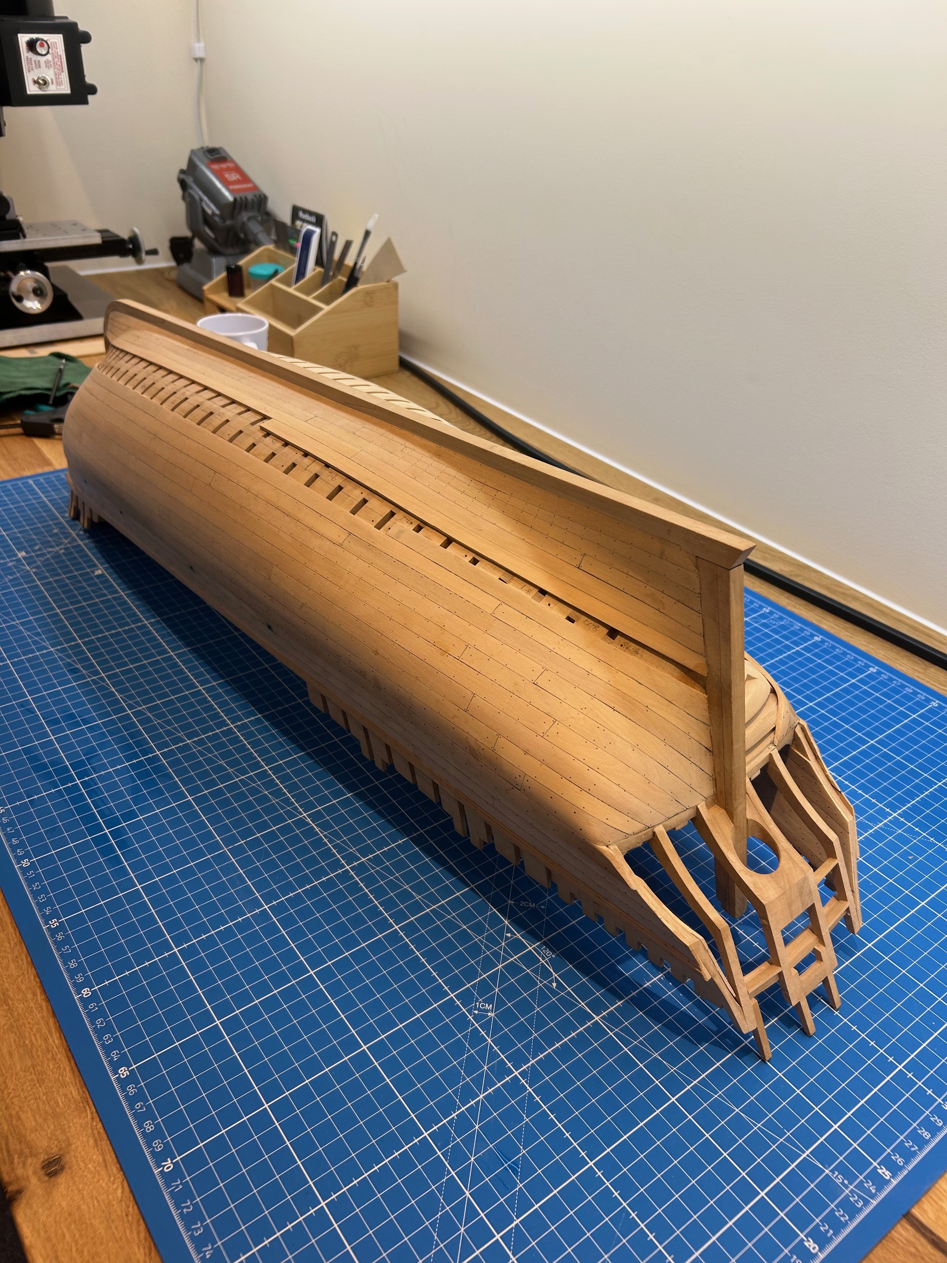
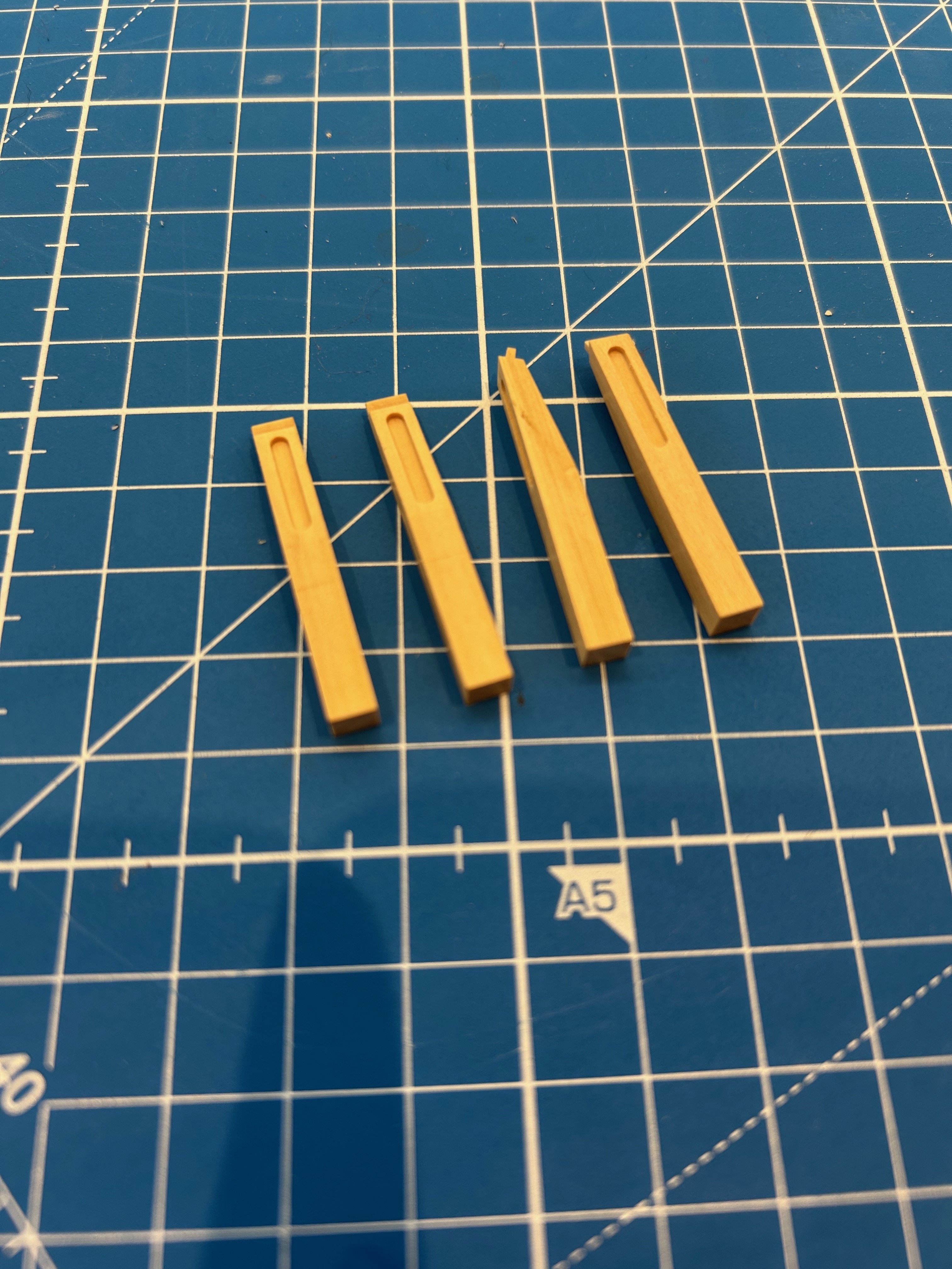
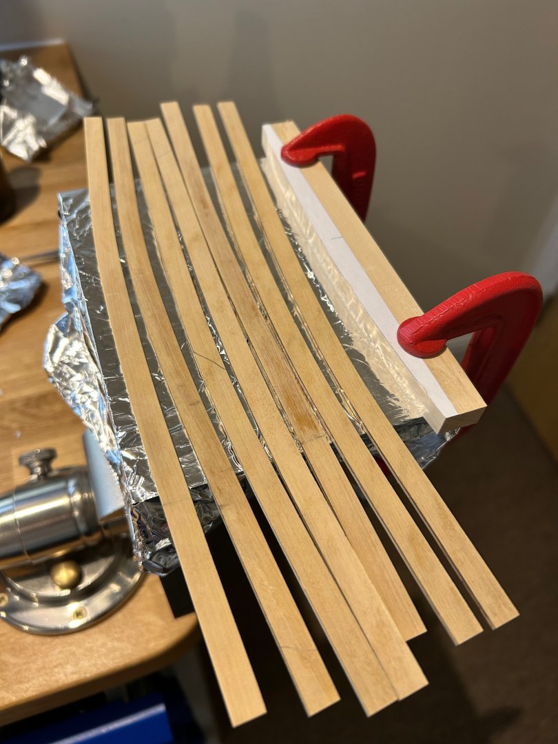
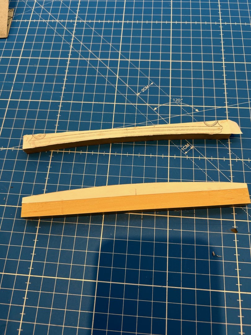
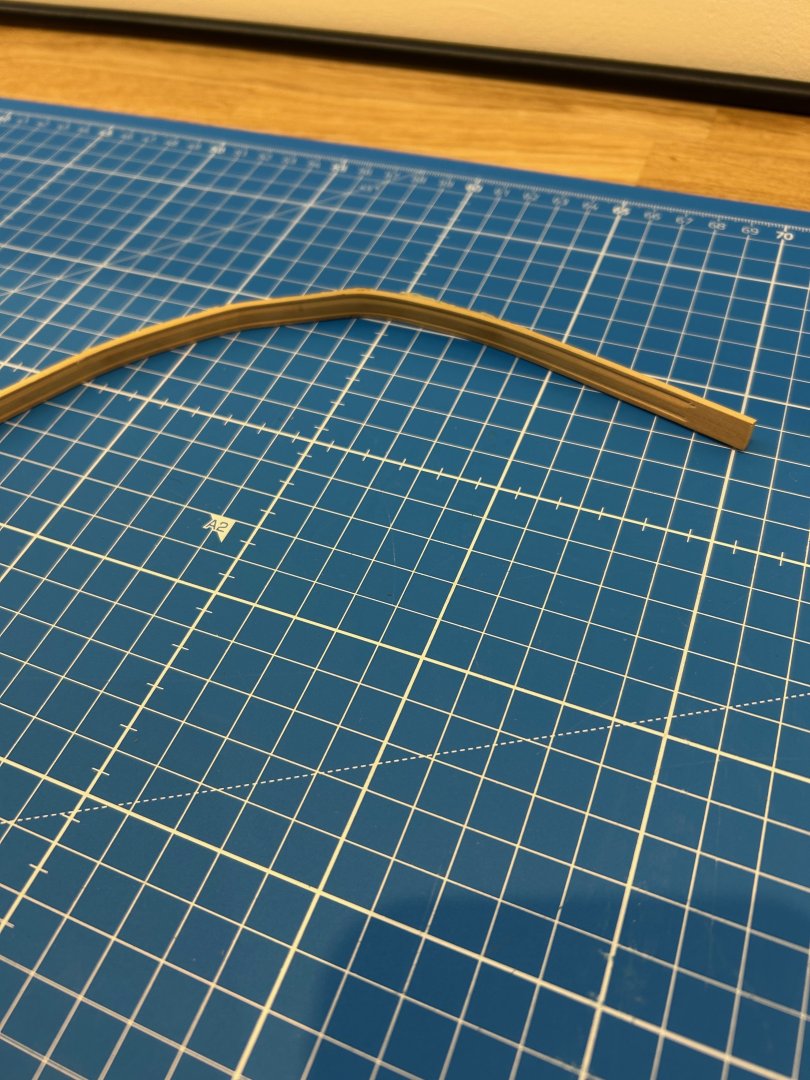
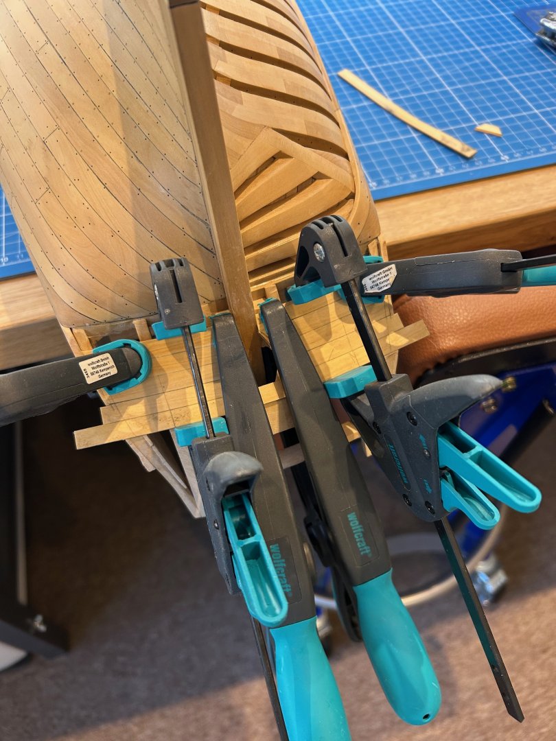
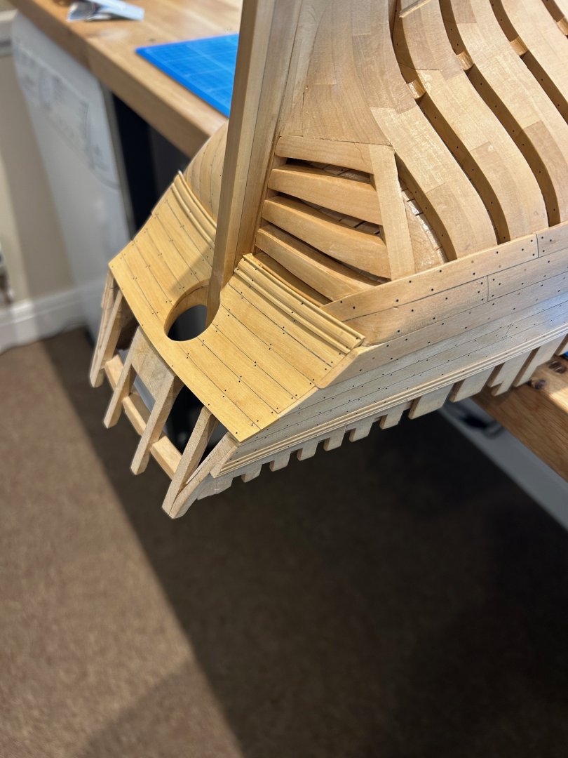
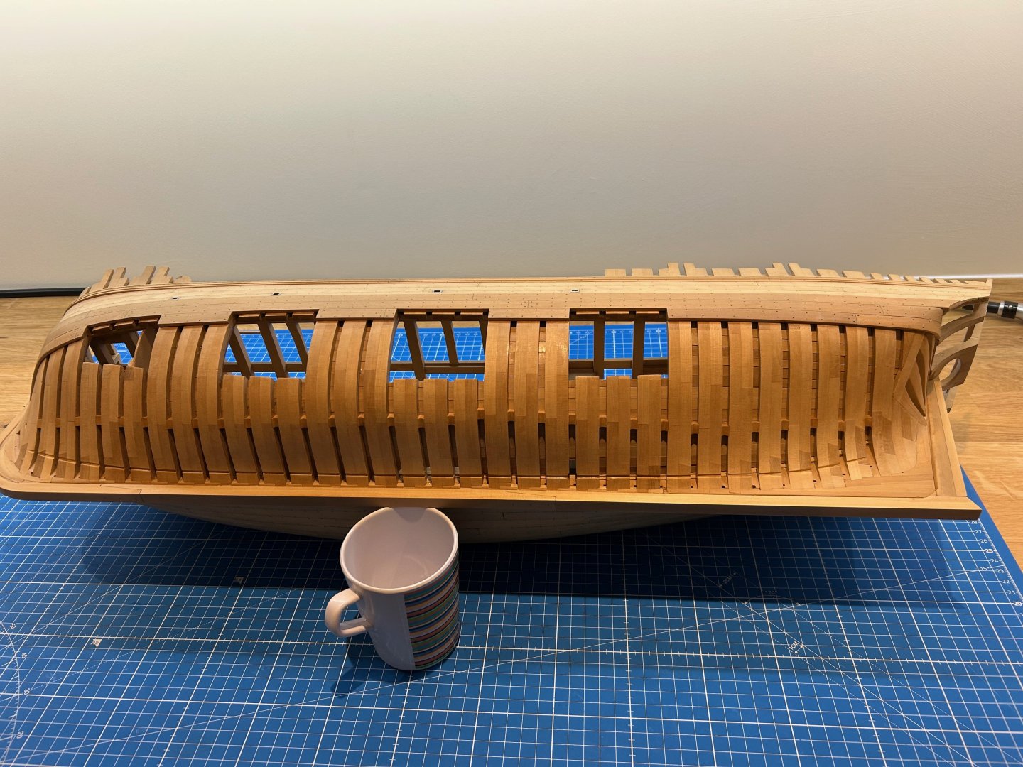
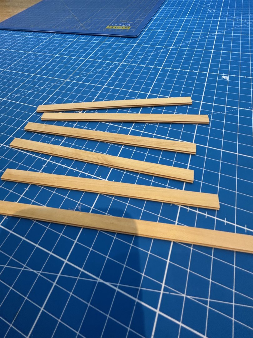
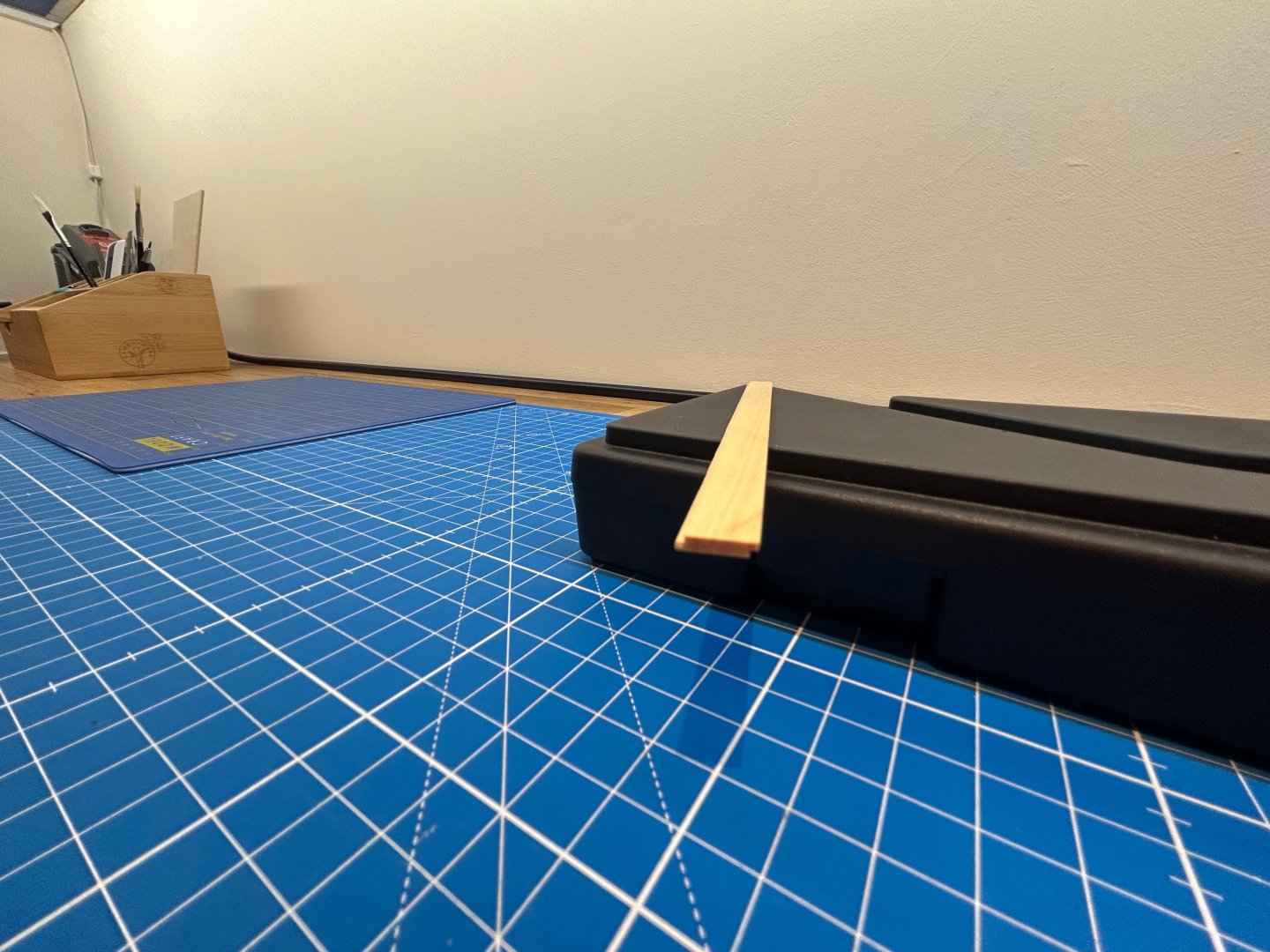
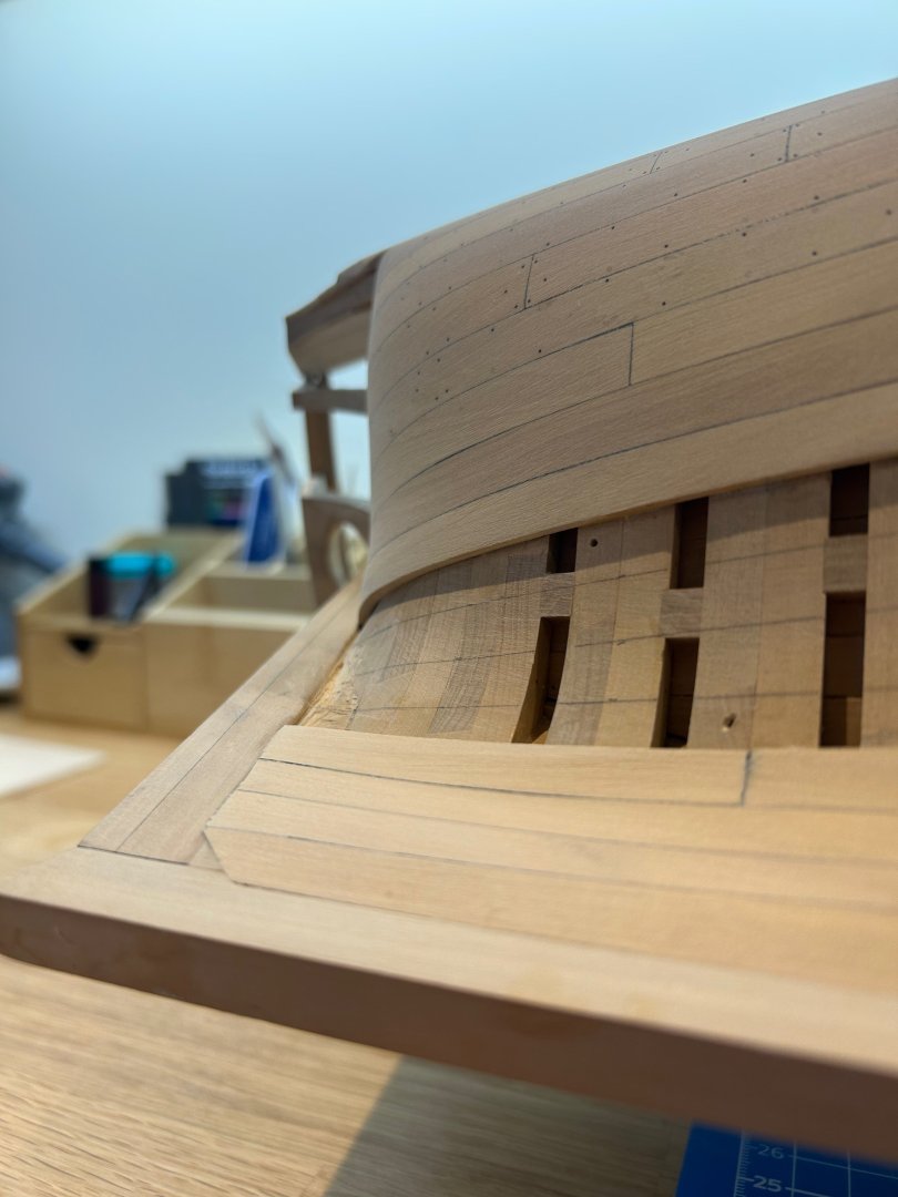
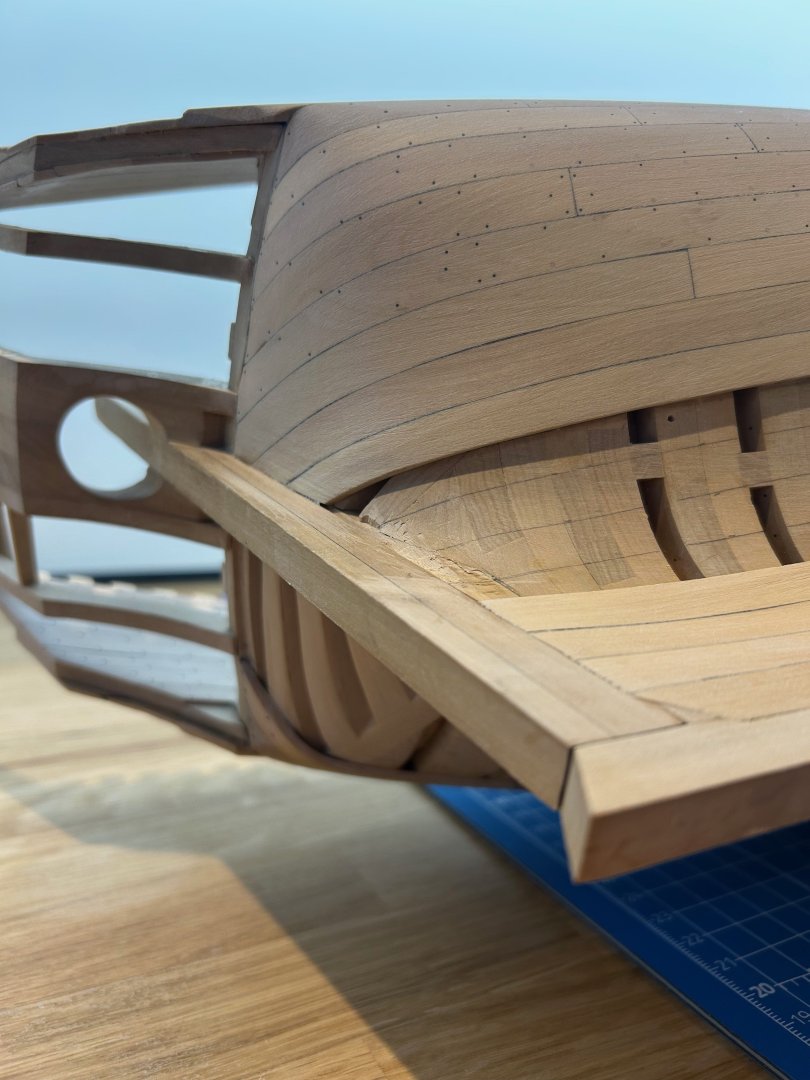
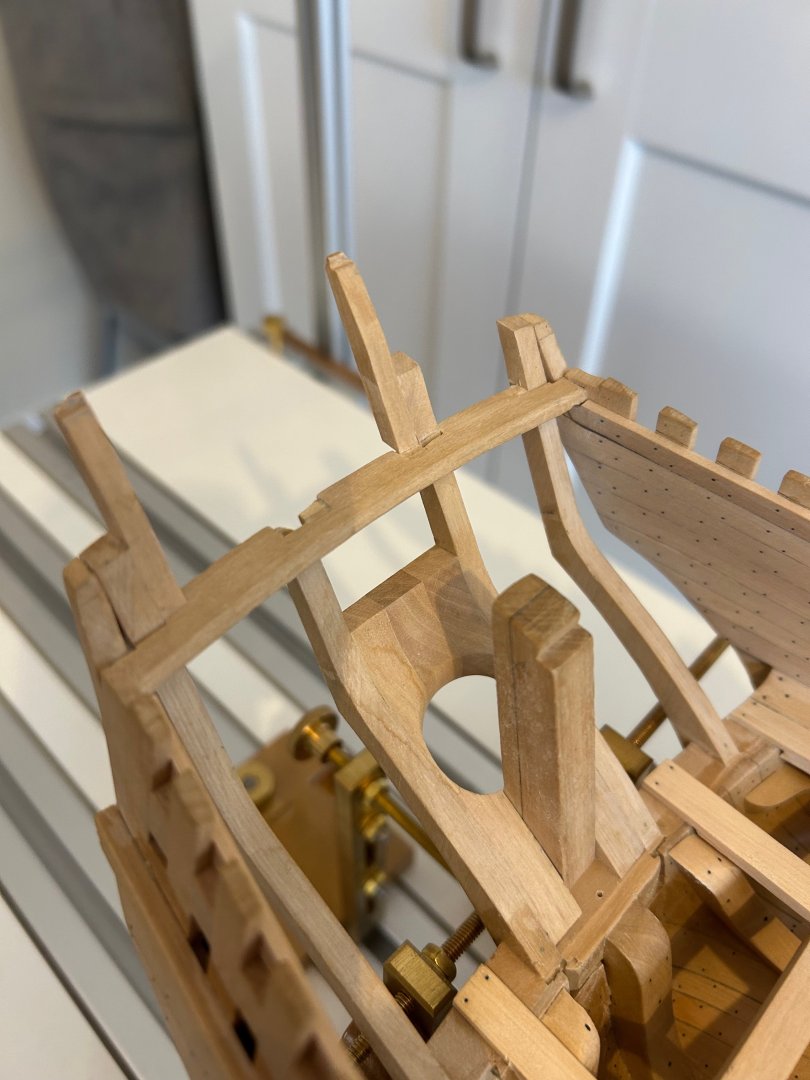
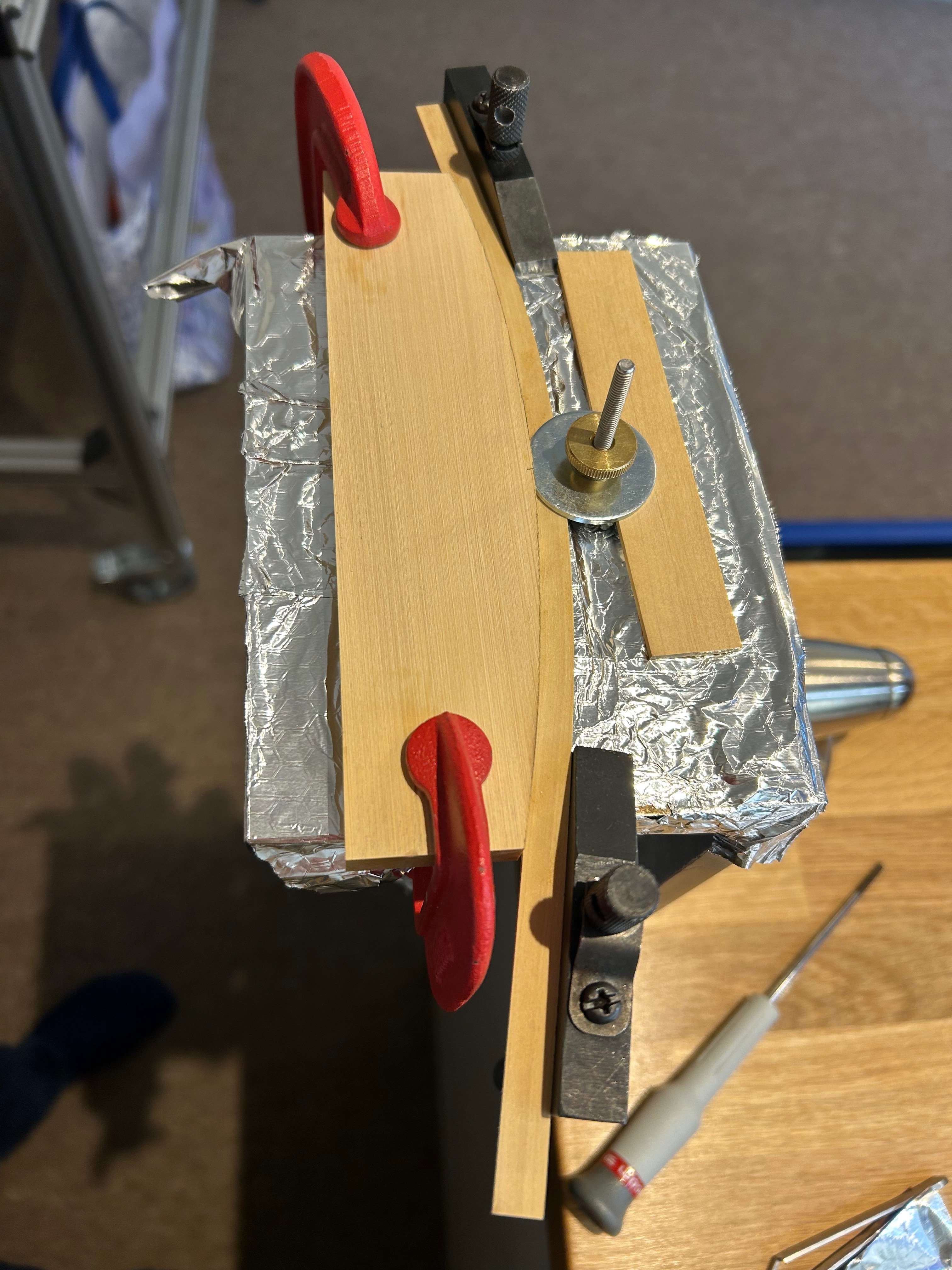
A very small update today - I'm back to work on Monday after a very nice week off Firstly the moulding below the stern timbers was made and fitted. This was my second attempt as the first one moved slightly whilst drying and left a small gap between it and the vault planking. Now I could have bodged / disguised / turned a bling eye to this but it just needed ripping off and another being made to replace it. What was left of the original moulding - I'm sure that I can make something else from it so it will go into my offcuts box. Now I'm not sure what this part of a ship is called but moving upwards I needed to make the stern timbers. The part which has the windows in? These planks are curved and I wanted to make them off of the model so that I can cut the window holes on the mill. So what I did was first was to just roughly edge bend some planks on a really simple jig. I use foil underneath as if the wet Castello touches steel which is the base it turns the wood black. I then made some vice jaws which matched the curvature on the drawings I then put all of the planks into a really simple jig and squeezed them all together with glue. I have ended up with what will hopefully be the planks that I will shape and use. If not I'll just make another one now that I have the jig. Thanks for all of the comments and questions - Mark

.thumb.jpeg.509f906012315d82309a56fa5652eea2.jpeg)

-
Hi Thunder and thanks for your comments 👍 That tool is a very old dremel router table. This was one of my very first tools and still use it occasionally. I pretty much stopped using it when I bought a spindle sander which is a lot easier to use than the dremel - Mark
-
Hi Max looks like a very nice build you are doing there and some of the frames especially the cant frames will be very tricky. I have never built cant frames like you are trying to achieve but I have learnt that each frame should flow into the ones next to it. I just look at what I've made and if I can see the flow of the frames its usually about right - great start; good luck and I'm following
-
A fantastic start to your new build and a very good choice of model too. I have been meaning to make some clamps such as yours for ages and I will before my next build. You have done this the right way around unlike me. Beautiful work and I think your gonna smash this so keep the updates coming and if its ok I'm following along
-
Thanks Justin 👍 Hopefully I'll have another update on the build soon
-
Thank you 👍 Thanks druxey - its good to be back building at last Hi Marc - good to hear from you and thanks
-
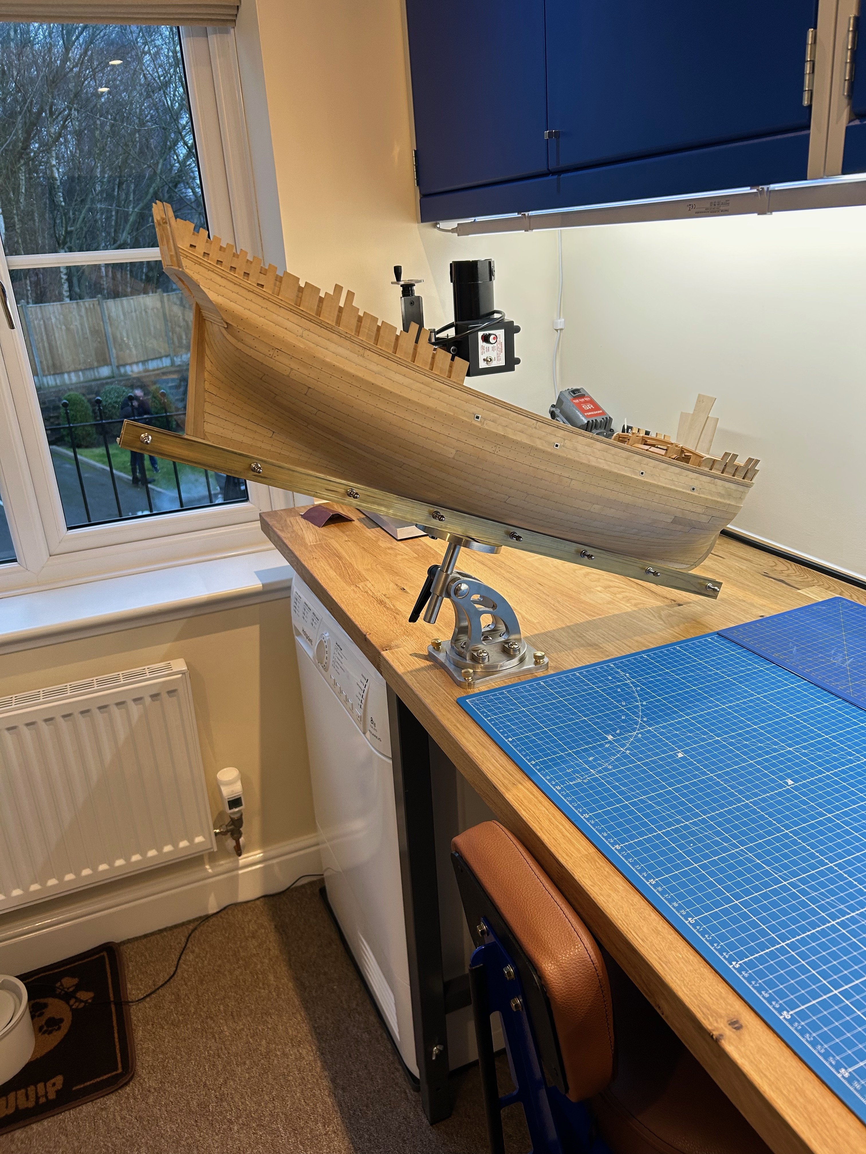
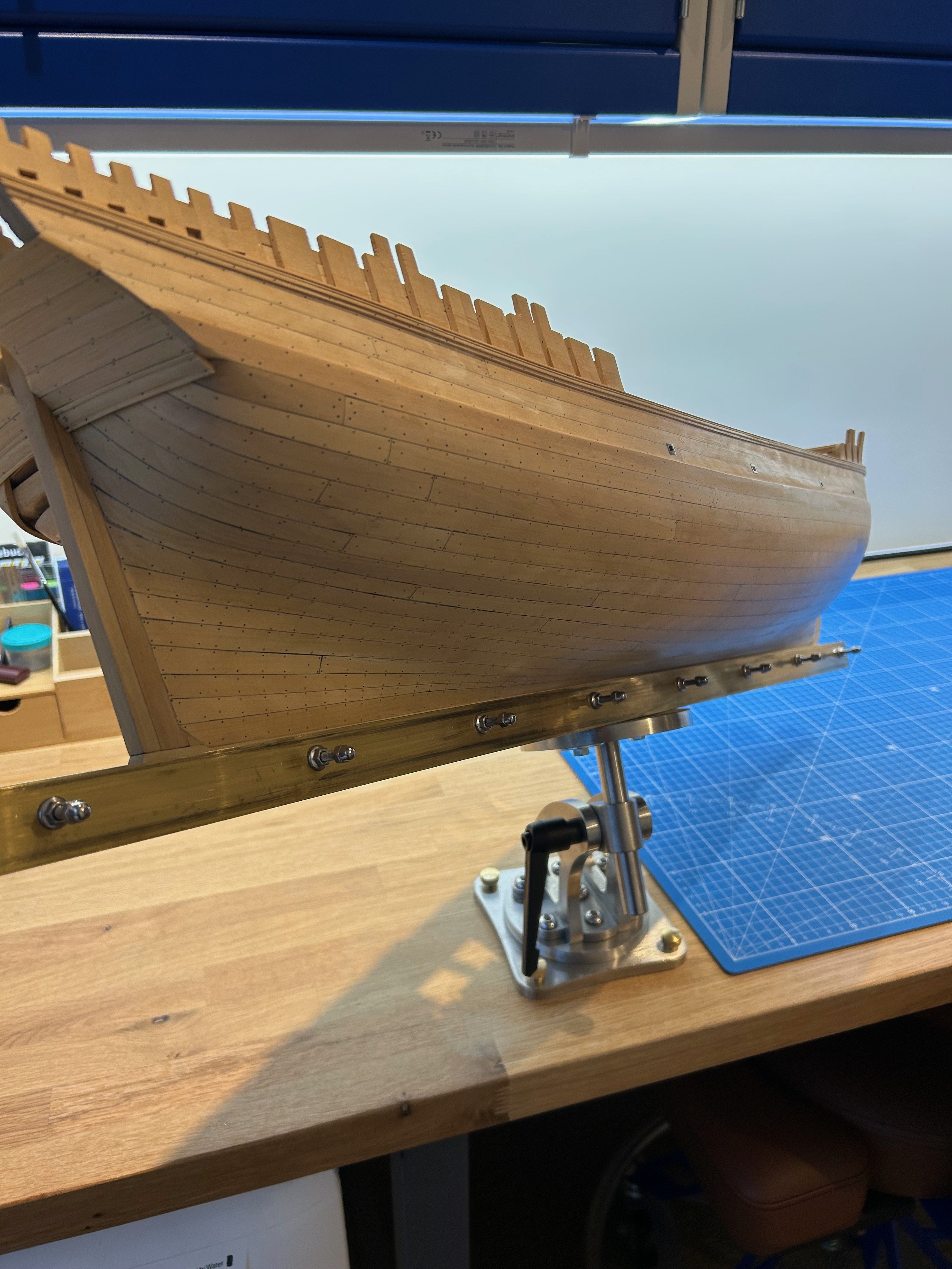
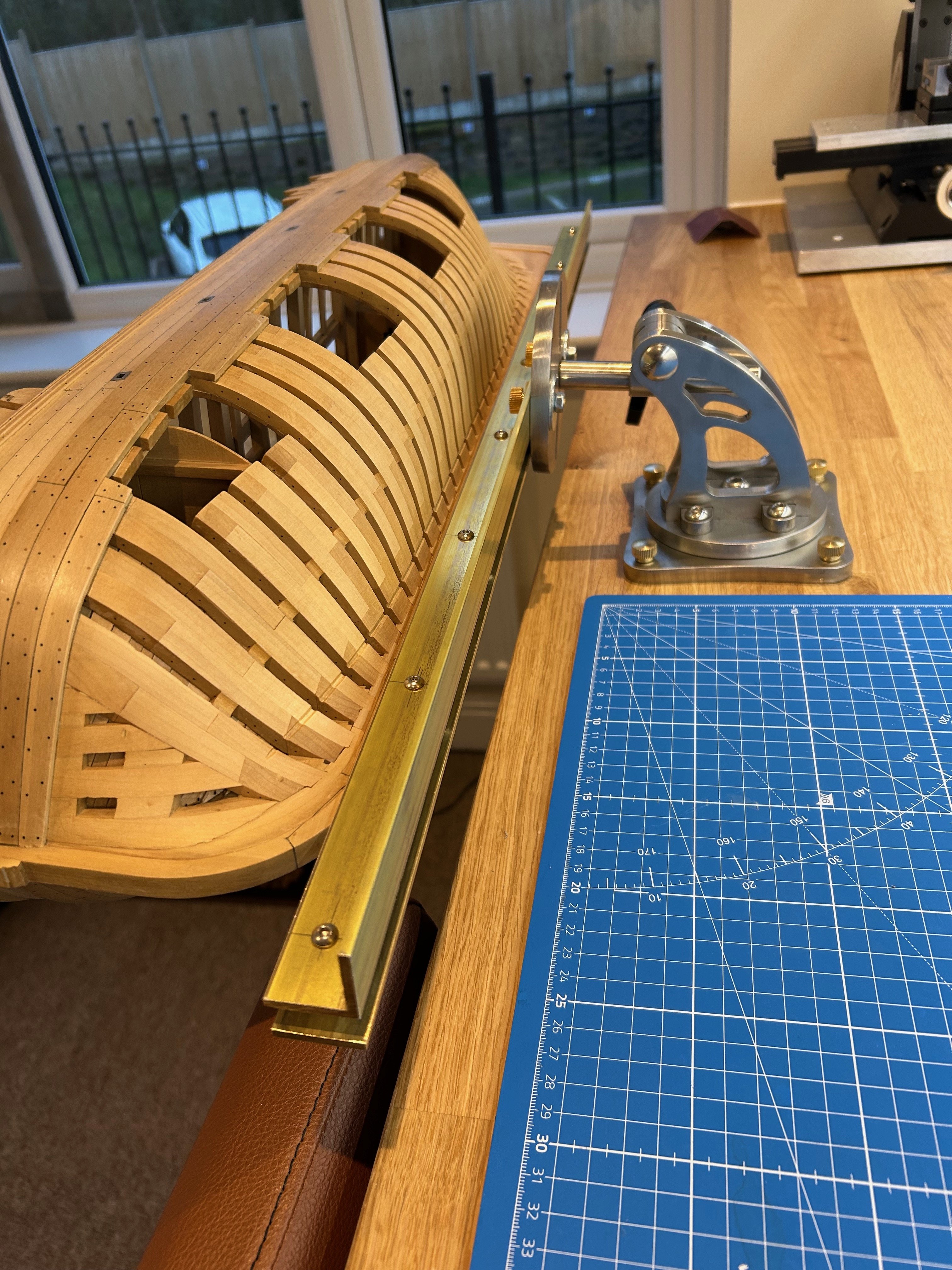
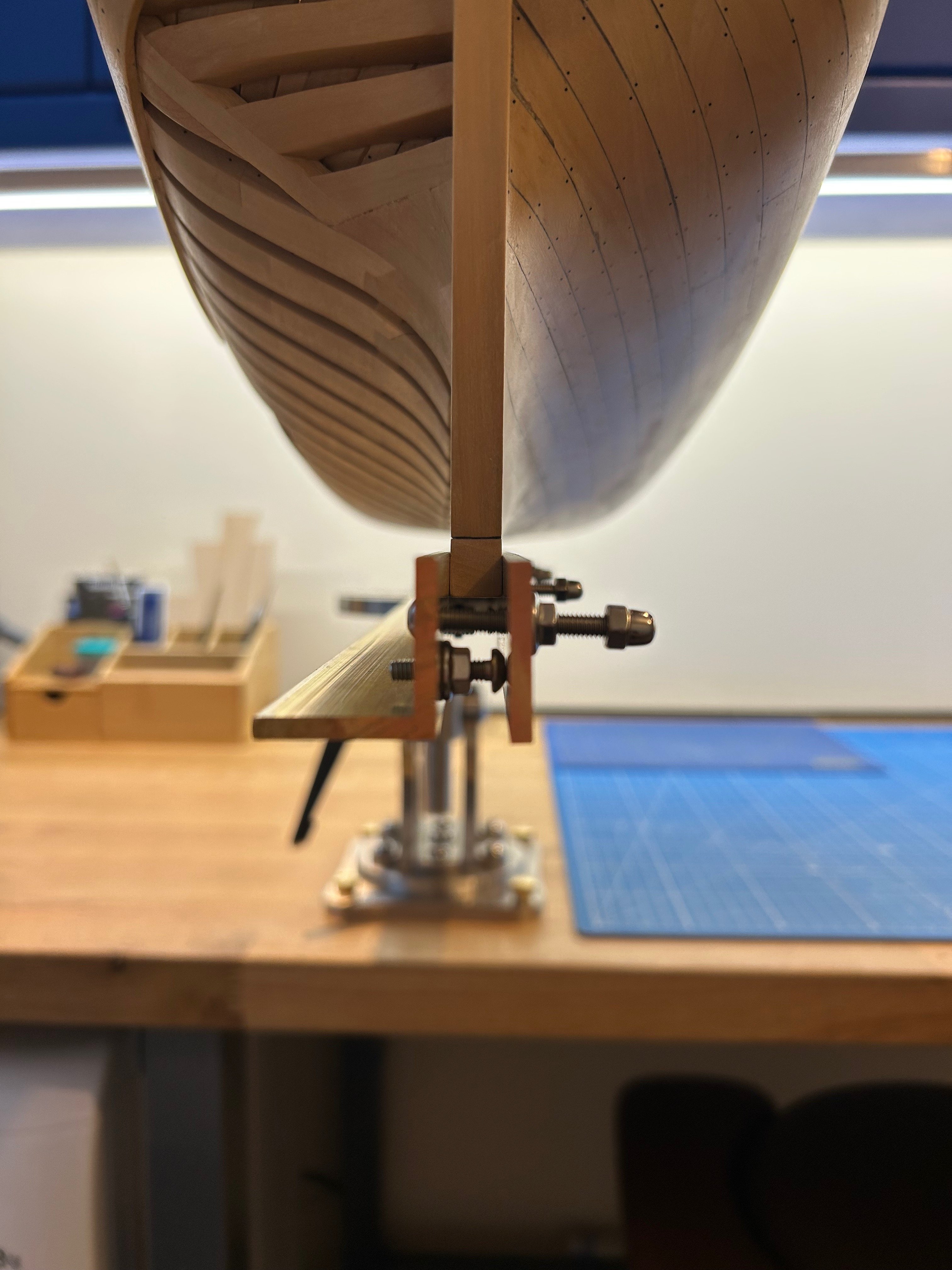
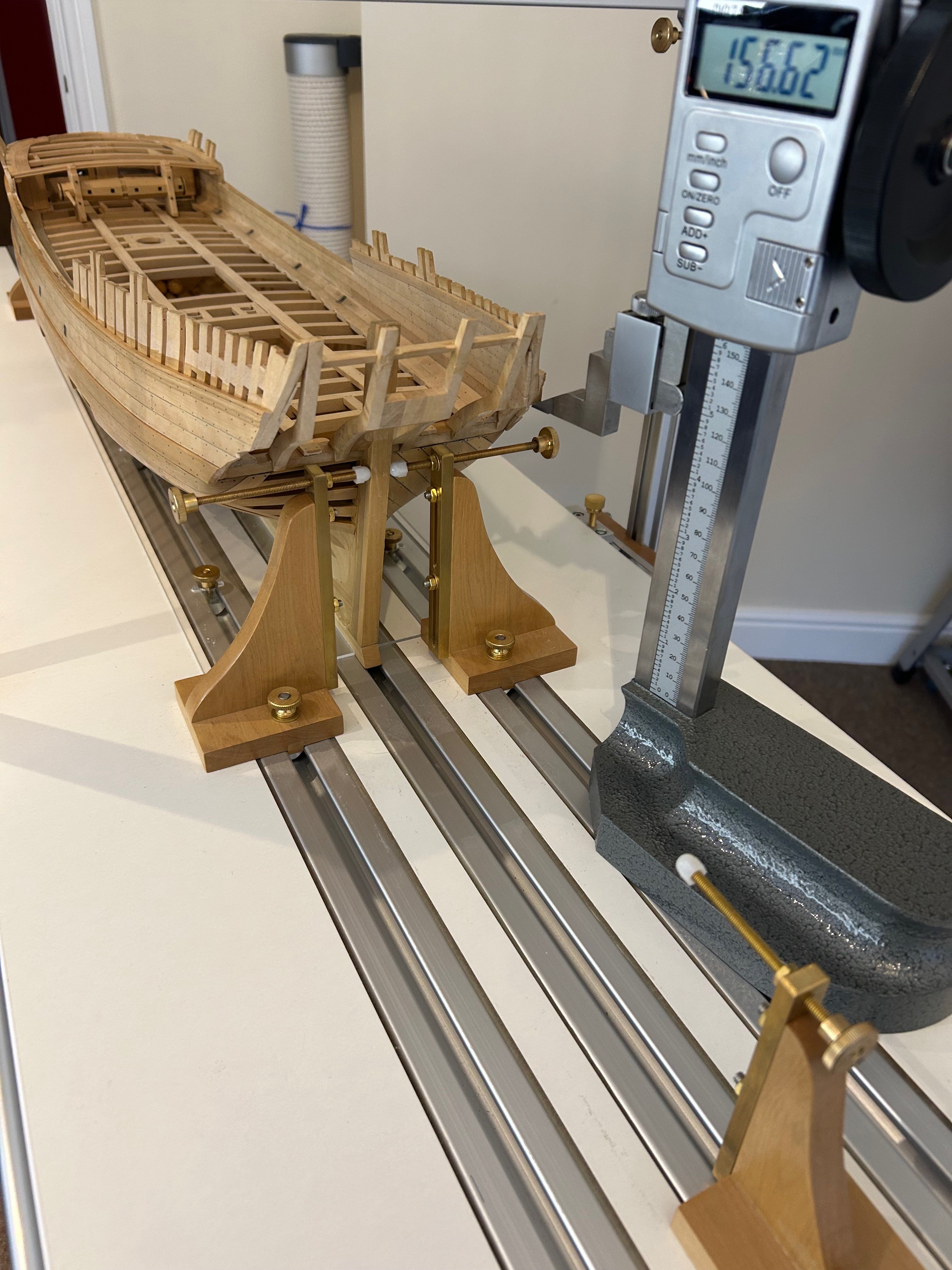
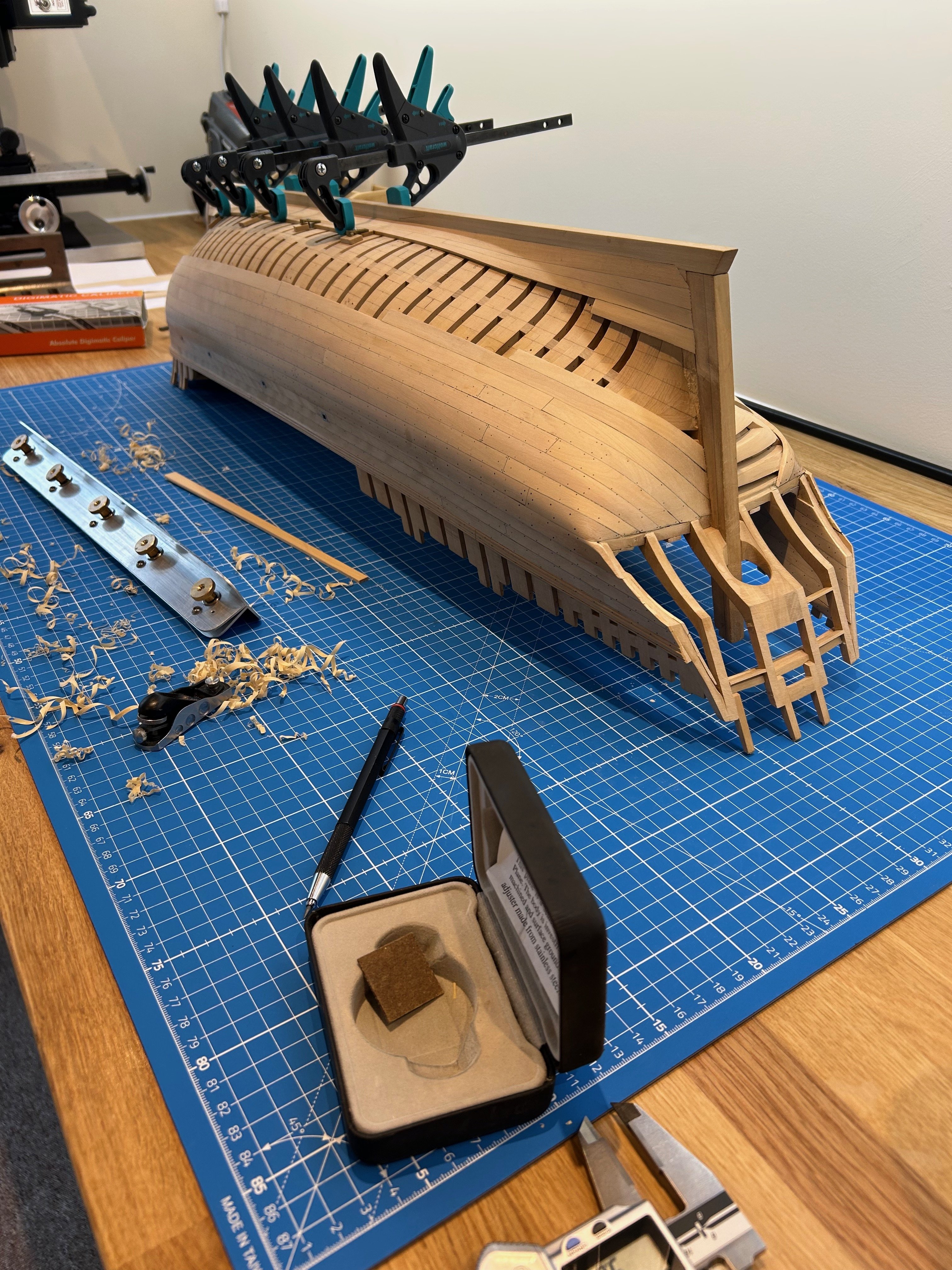
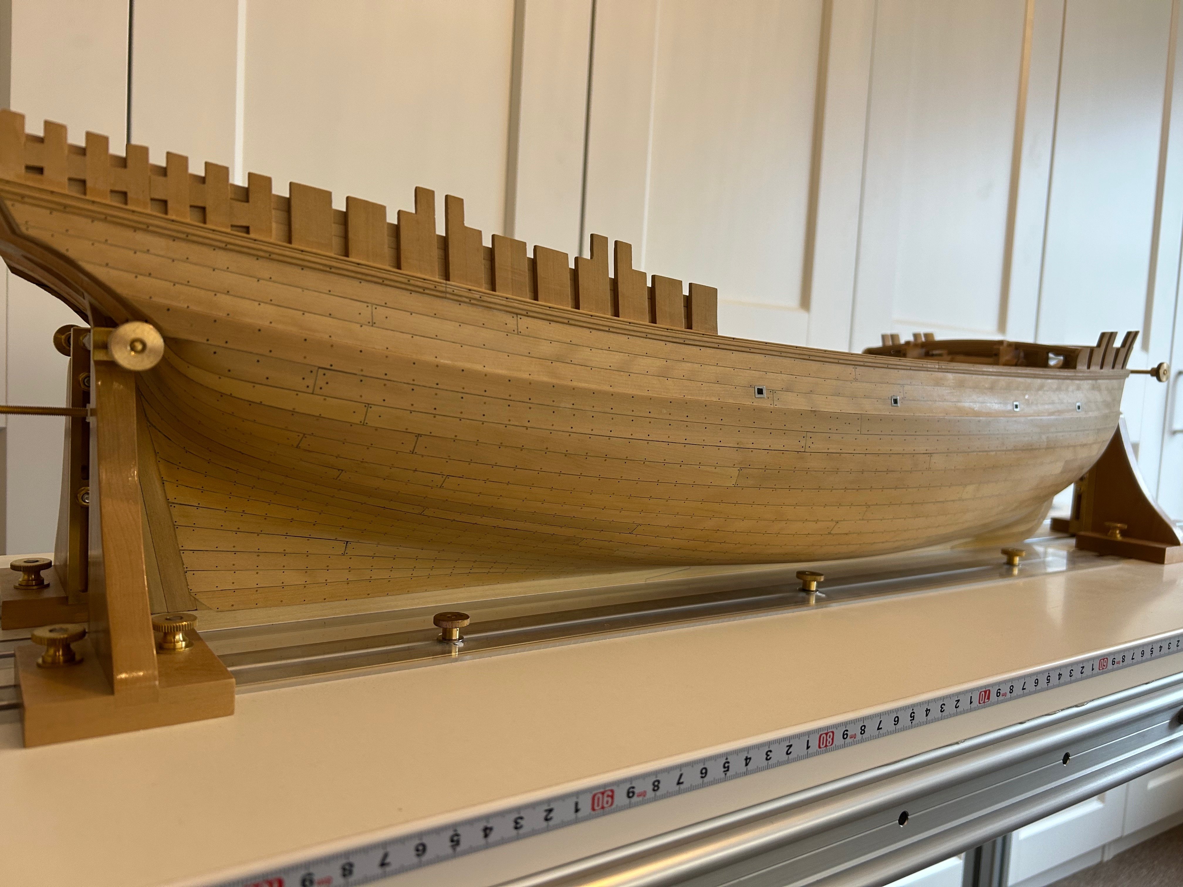
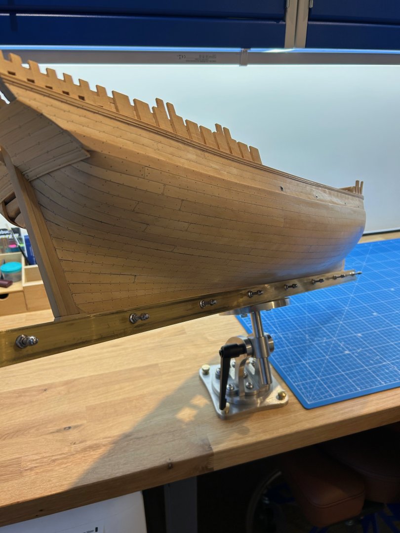
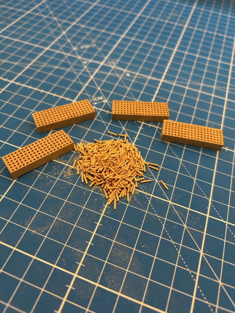
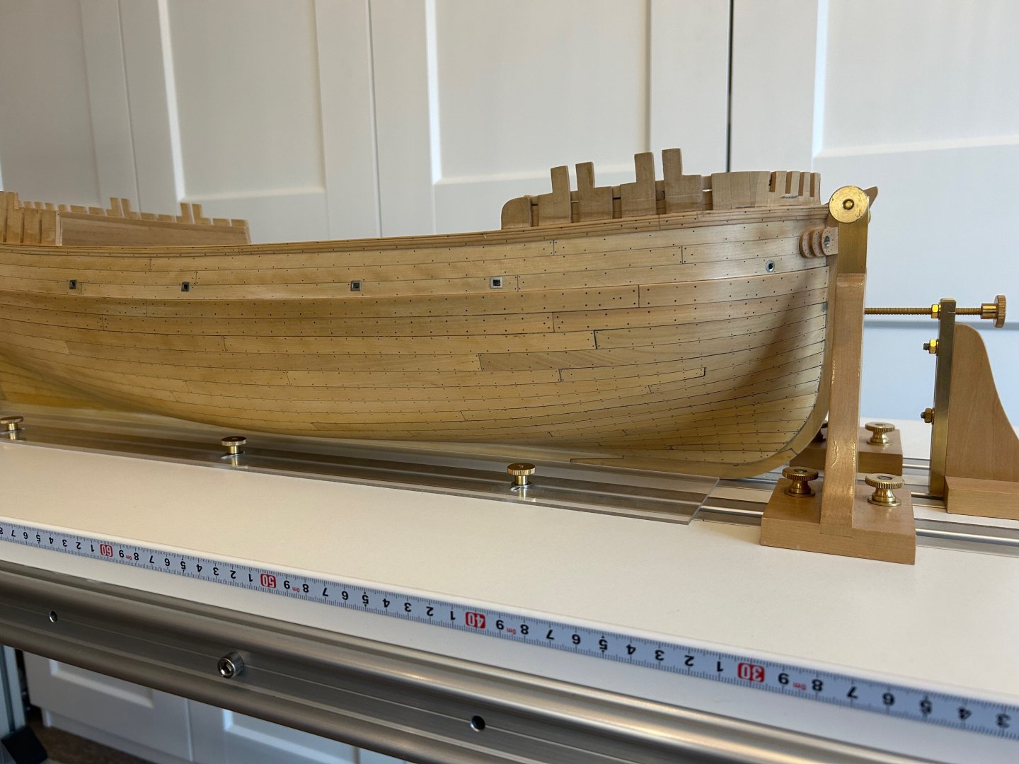
Thanks SaltyScot - My height gauge has become probably one of my most important bits of kit. All builds need a datum and mine is the very bottom of the keel. So I use this tool to check pretty much everything. They can be bought for less than $90 now but they don't have to be digital. I just wish that I had owned it at the beginning of the build. Hi Justin P - I'm fortunate that this is sometimes a team build. I have a book by Adrian Sorolla that explains the entire build of this little ship. I also have G. Delacroix who actually owns the monograph who is a member on here. He answers so many questions for me regarding this build which I would otherwise struggle with. I also have the 1000's of members of this forum that often put me right - so don't quit go build a ship Now I said that I was going to build a heavy duty keel clamp so I did - this is not going to be everyone's cup of tea but here's some pictures. Cheers to Toolmaker who encouraged me to share this. I've built in some room for growth as my next ship will be a little longer - all I can say is that it's completely over engineered and extremely strong Mark


-
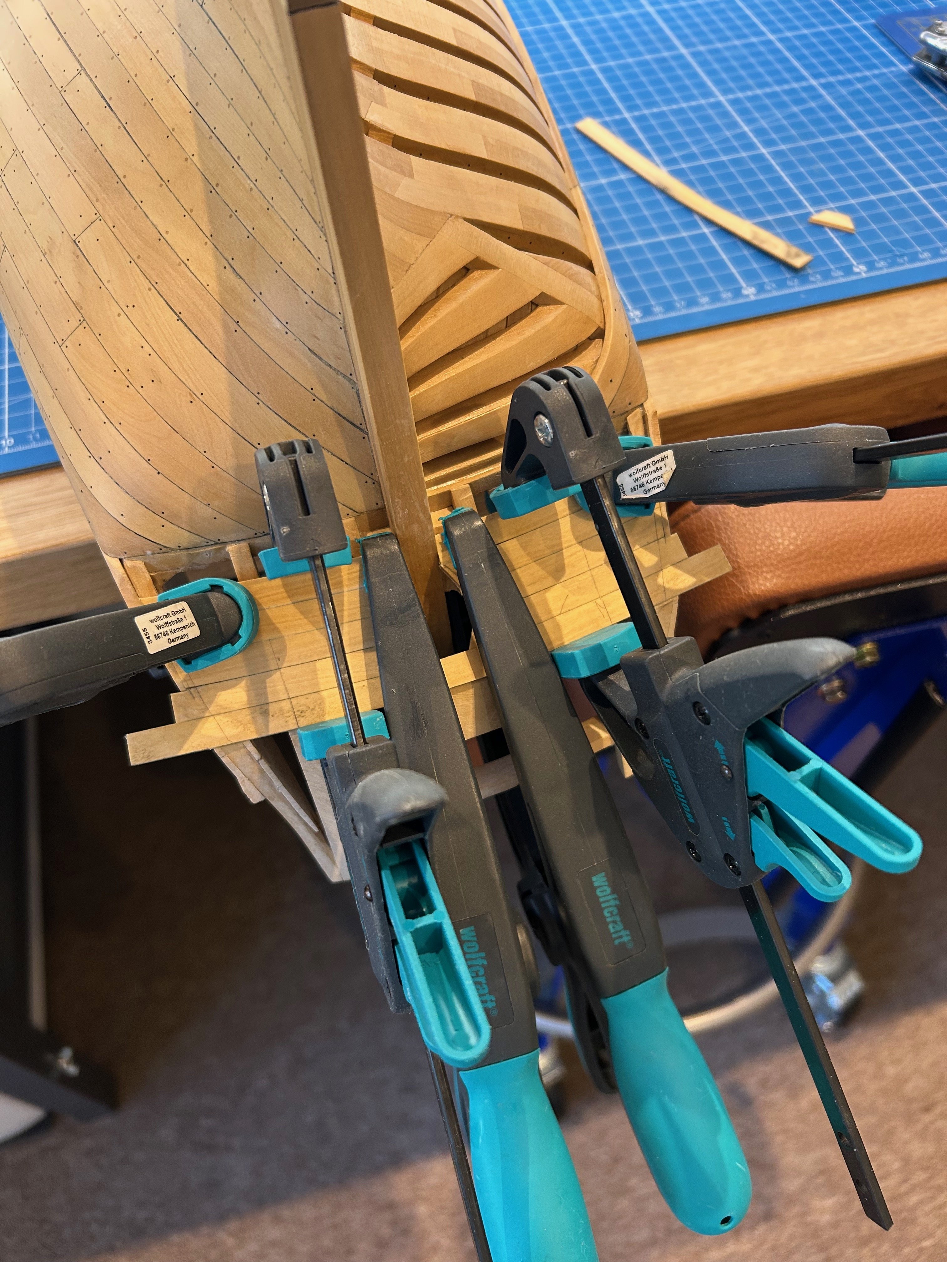
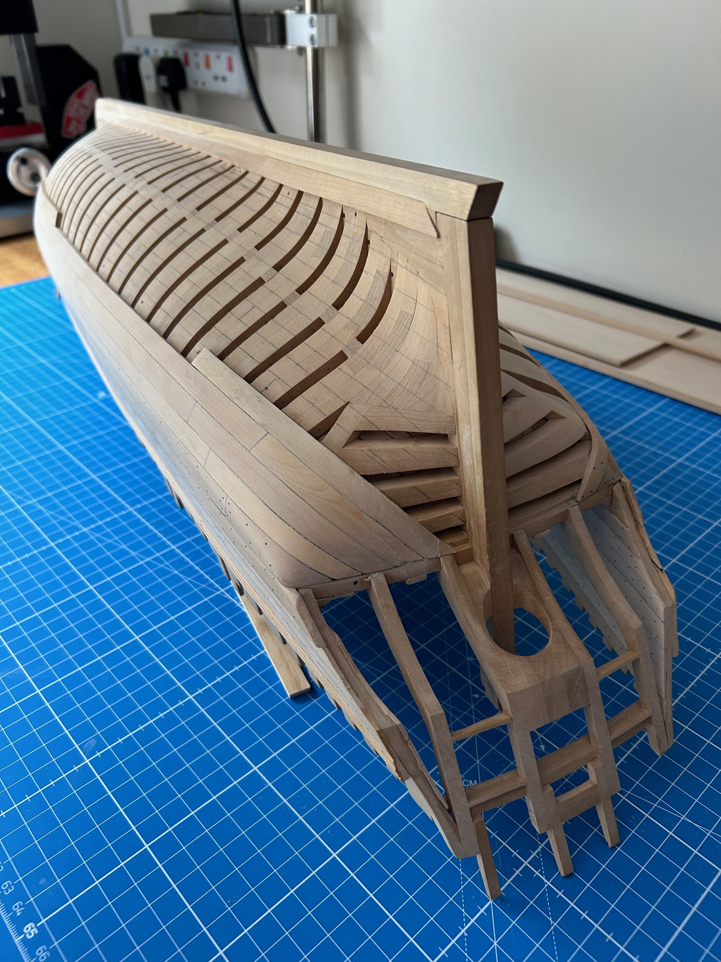
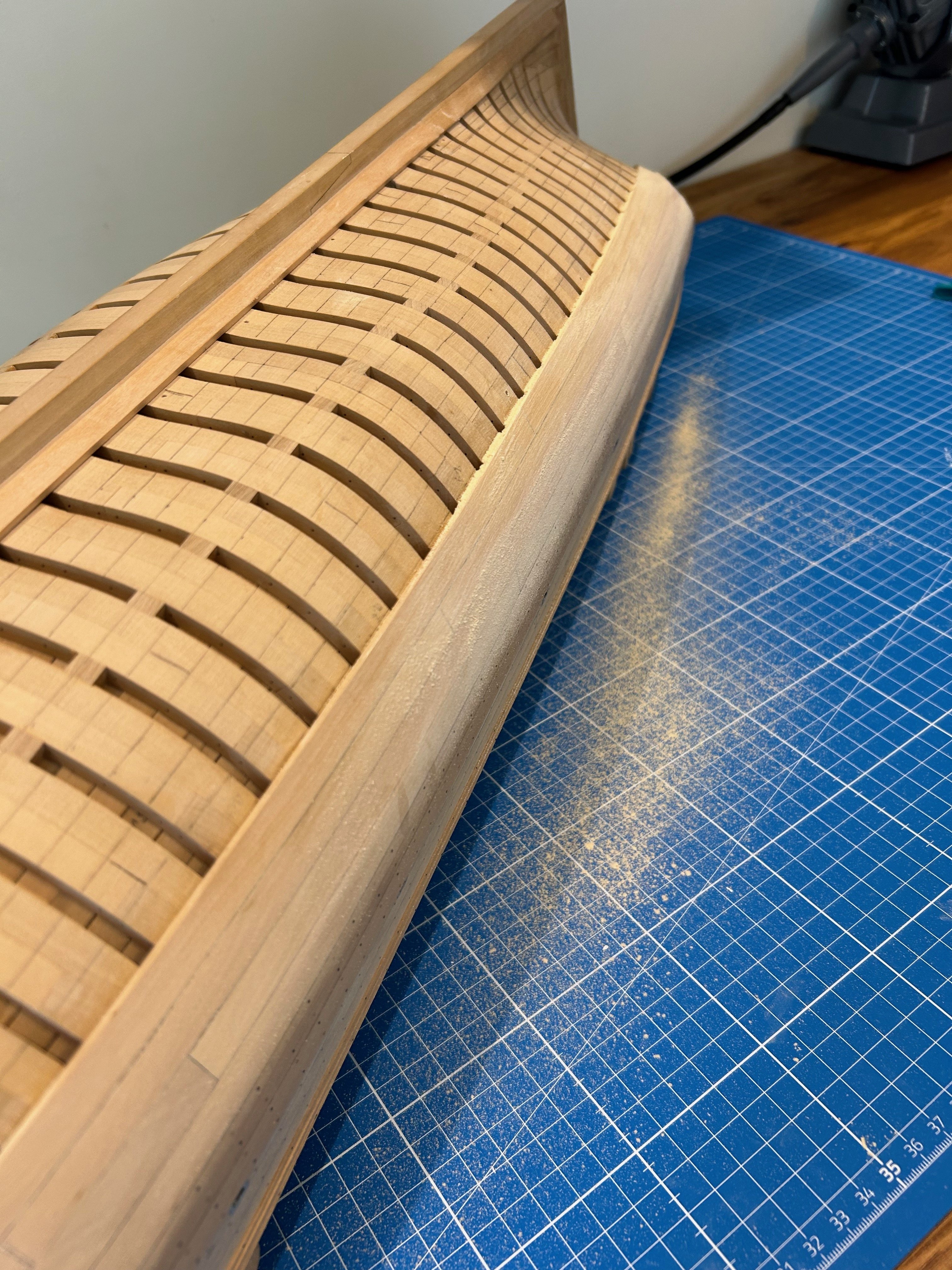
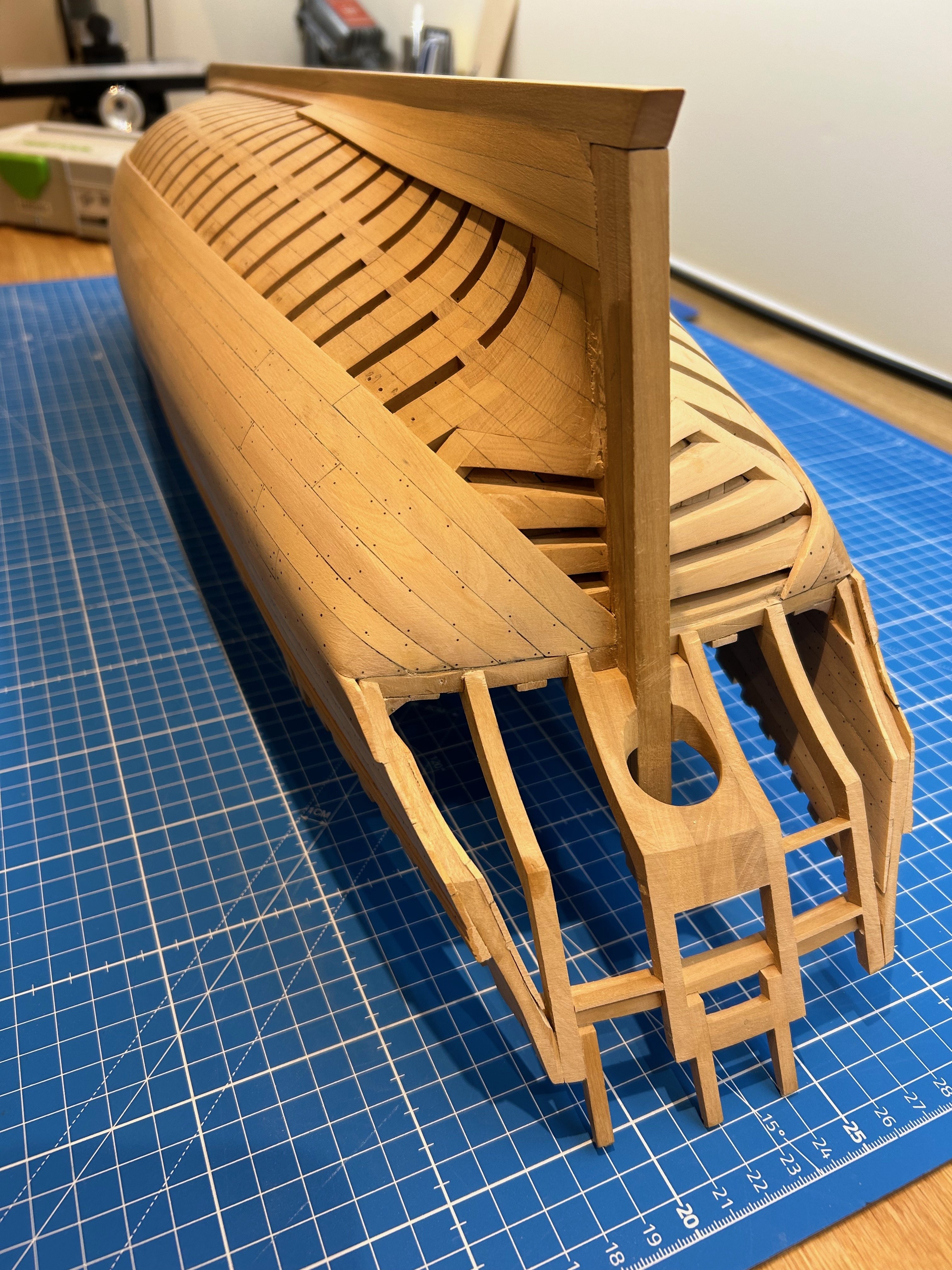
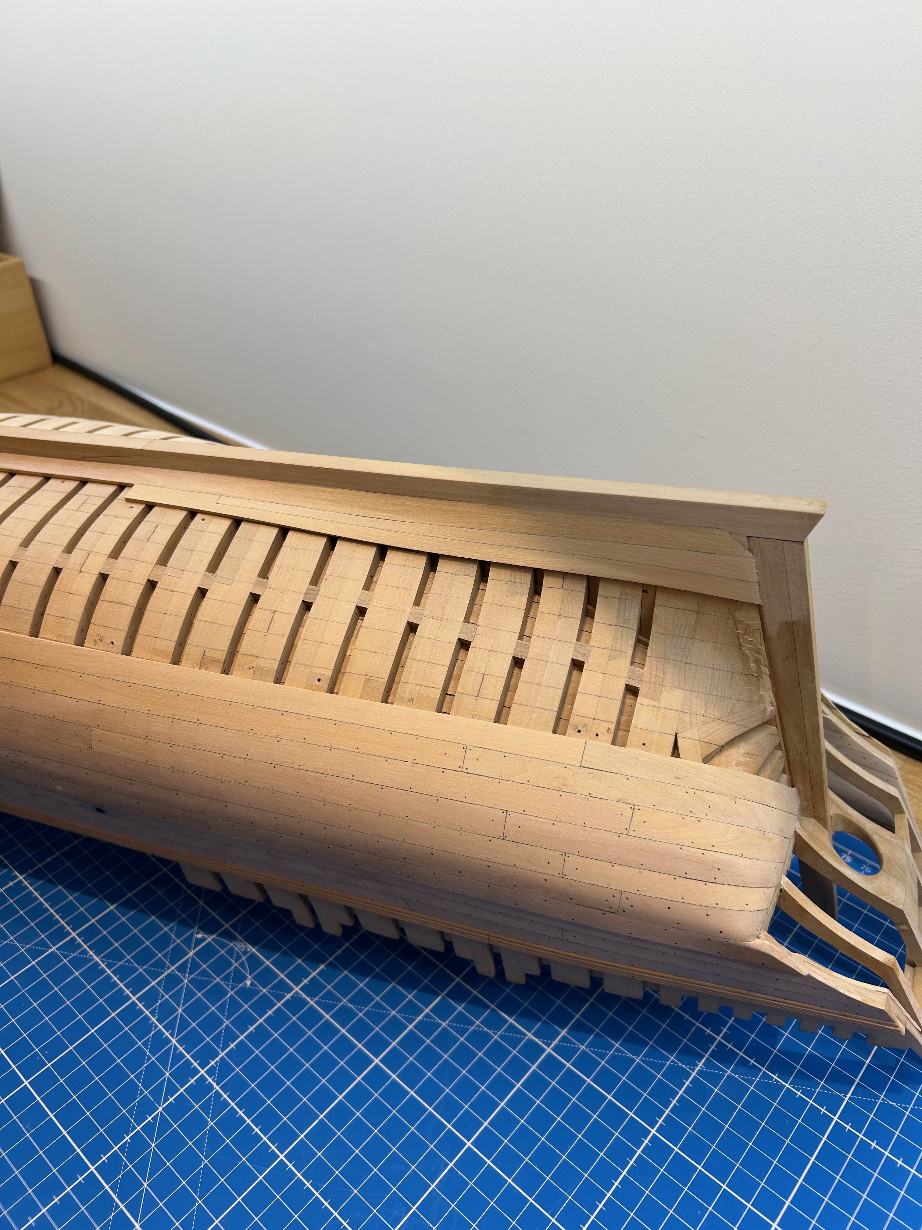
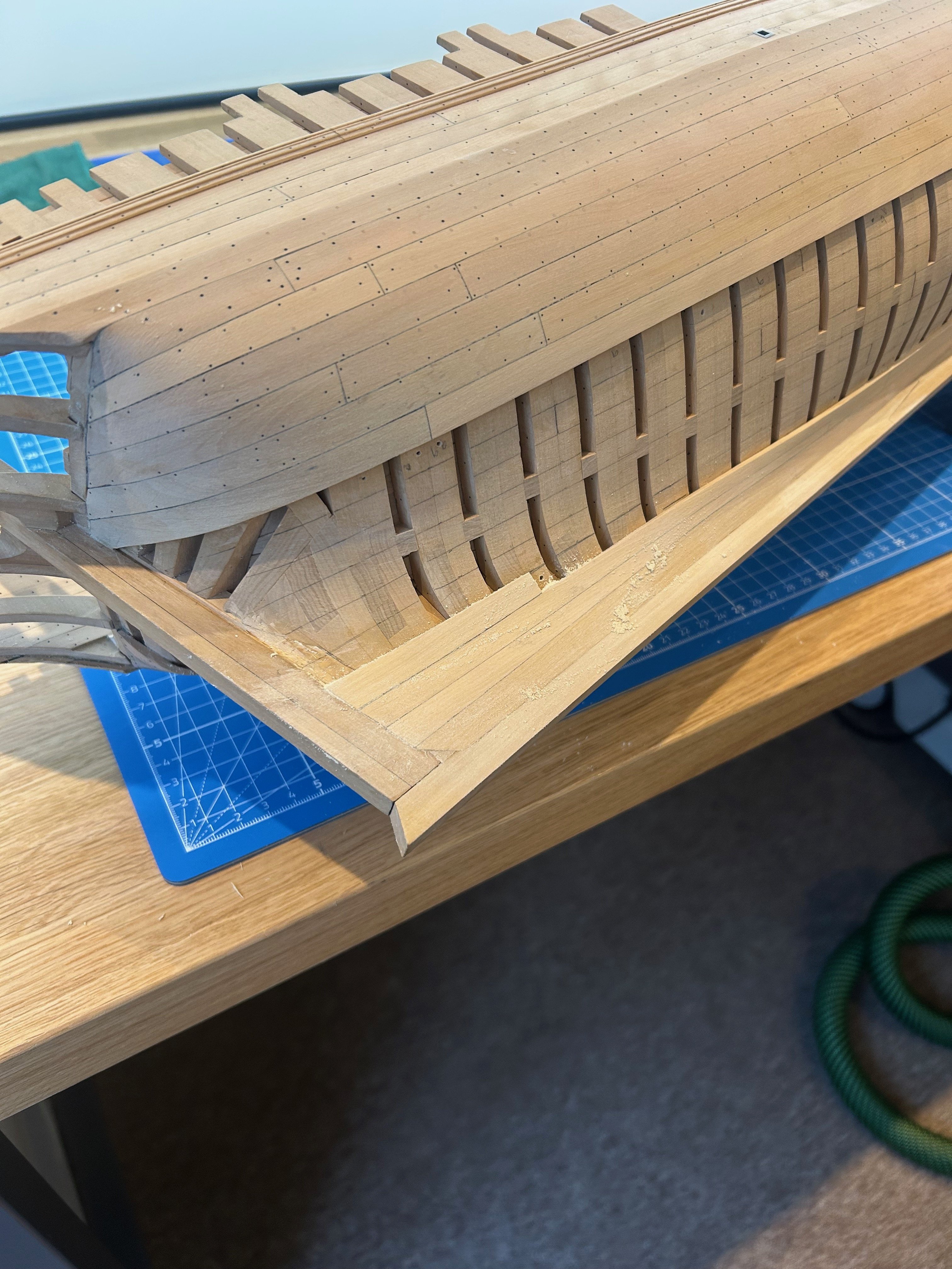
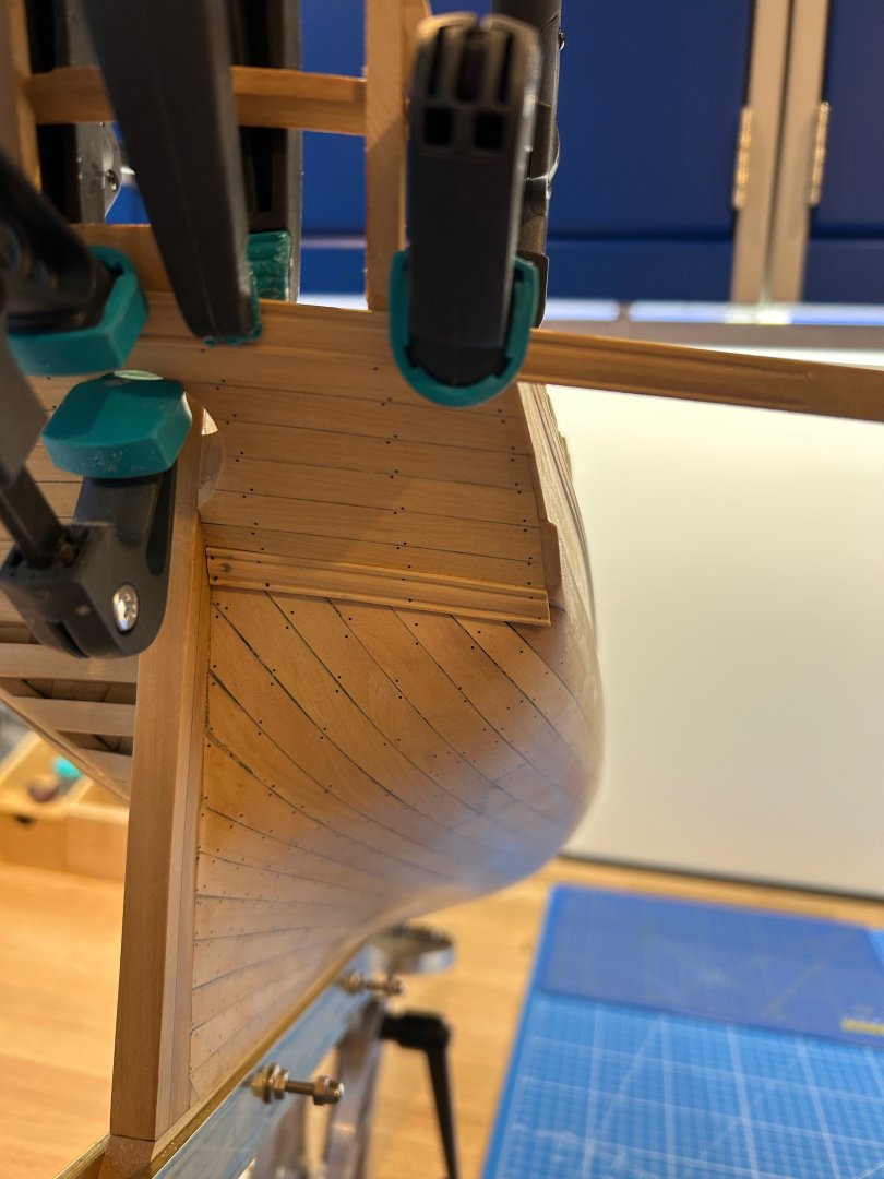
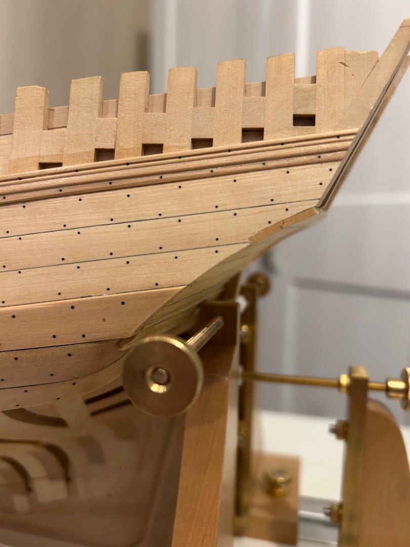
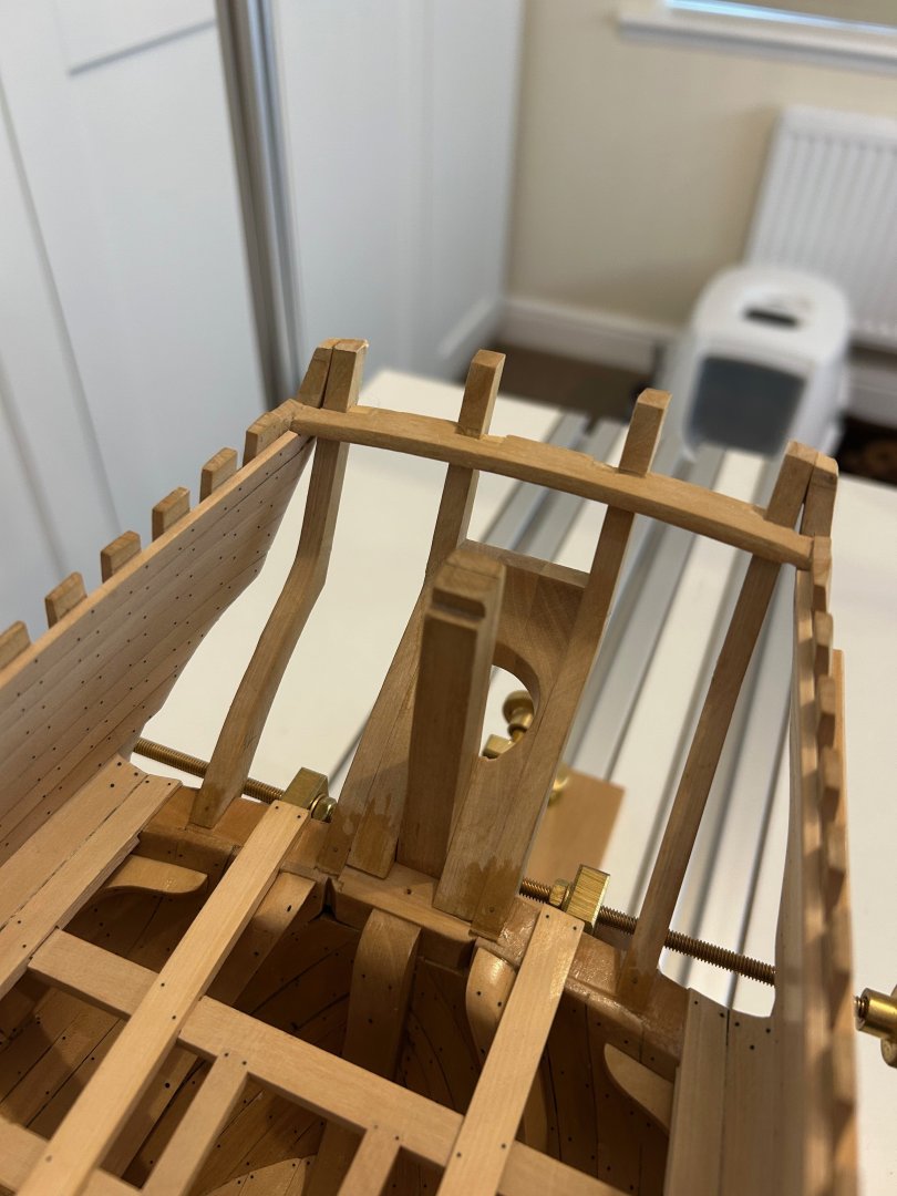
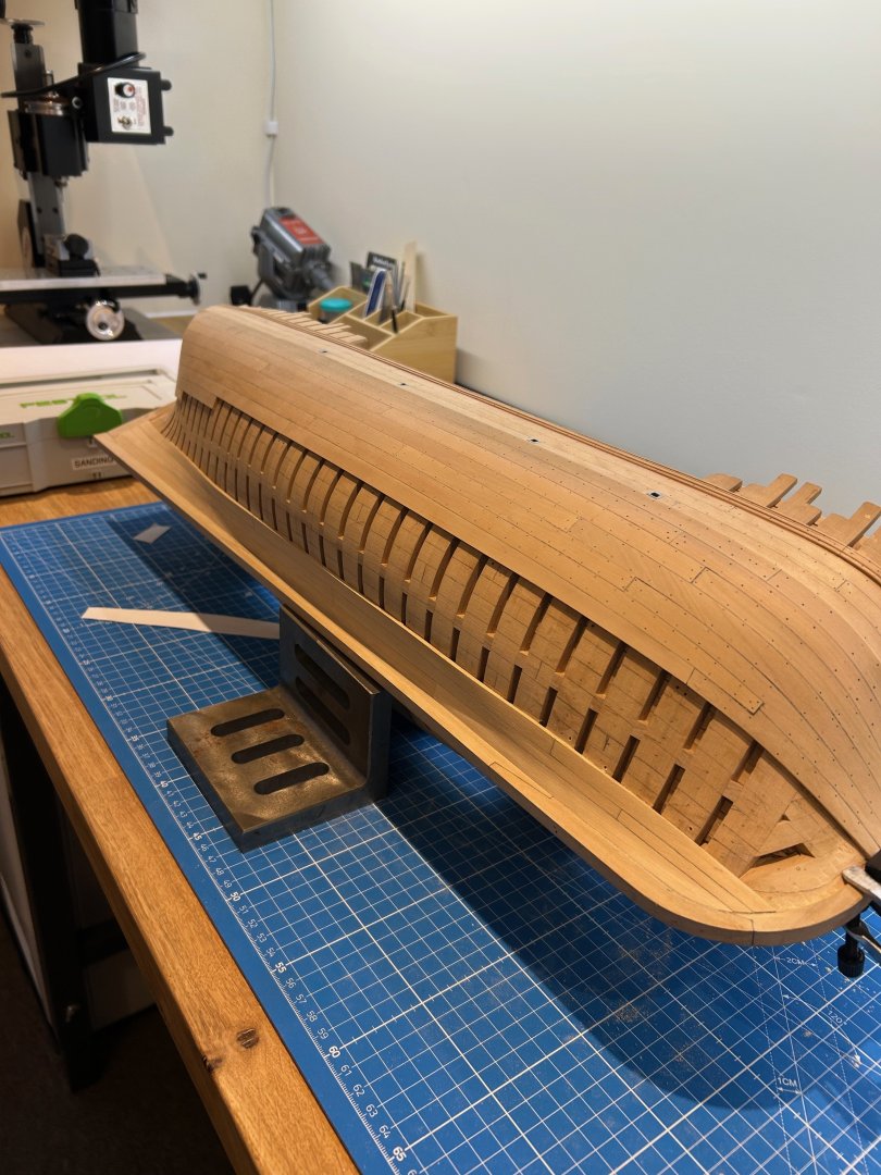
Some more done Before I started the planking I just did a quick check to make sure it was all square as I didn't want a wonky stern 🤣 I did this because I fitted it a long time ago when my measuring skills and equipment wasn't as good as today. It was only 1mm out on the port side so I squared it up with a rasp. All of the planks are curved so I pre-bent them all just using Chucks edge bending technique and then got to work fitting them. The last plank was the hardest as it's a moulding which makes the transition from the counter timbers to the overlap of the stern planking. I made a scraper and shaped it on the bench. It was tricky to fit and I lost some of its detail but all in all I think it looks ok. I like the side detail where the first 2 planks sit flush with the outer planking but the rest sit behind. Its also the only place where you can actually see the shiplap joints too. So I'm going to continue working on the outer of the stern working my way upwards for now. More mouldings to make and more planks to pre-bend for the construction of it. Mark


-
Hi You use the smaller one 👍 If you look at the drawing there is a double arrow pointing towards it - I had exactly the same question as you did when I arrived at this point in the build. There is also another drawing which will help you with the curvature of the hawse timbers. Le Rochefort is a single planked ship and not double planked I hope this helps you - Mark
-
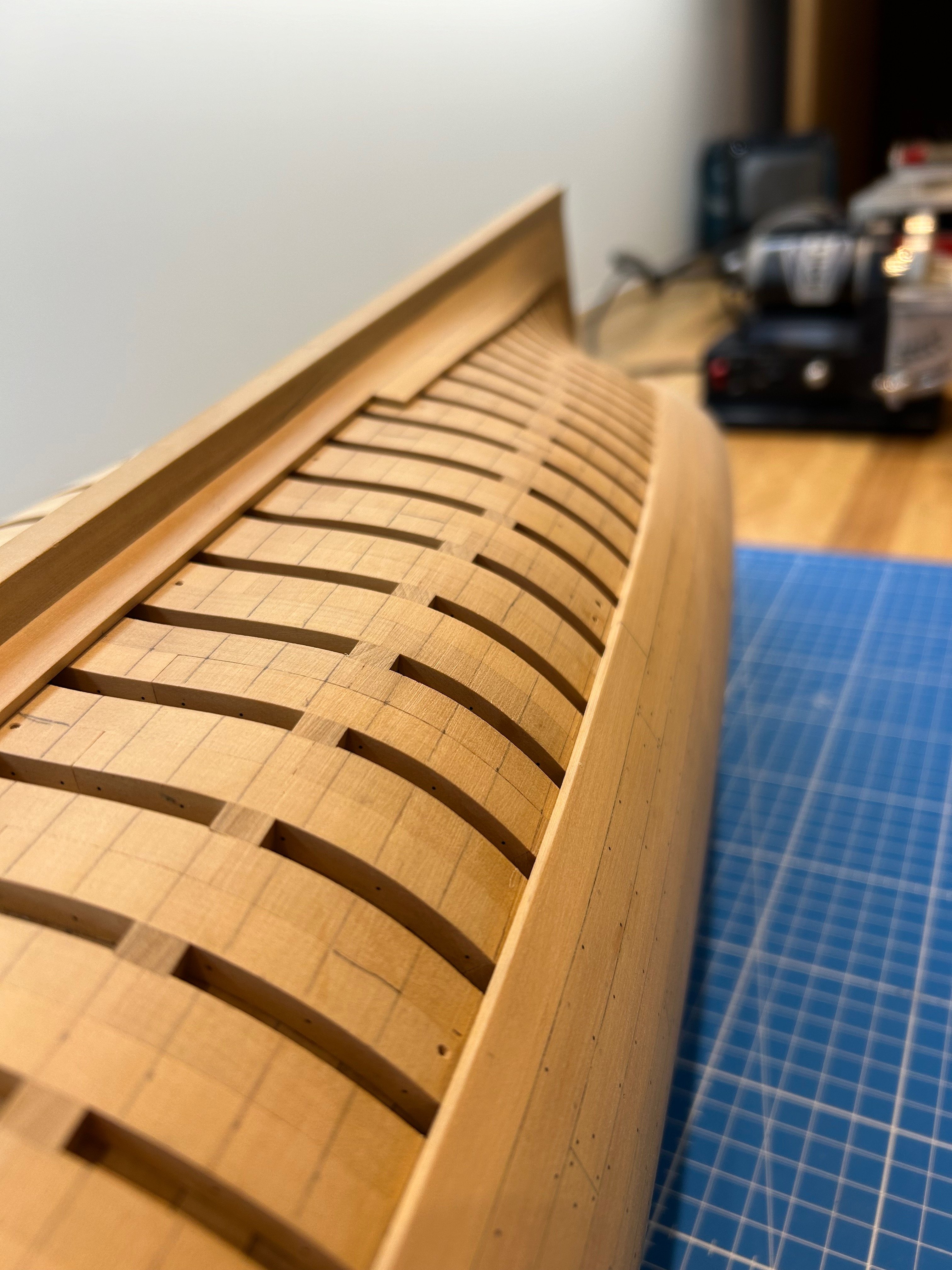
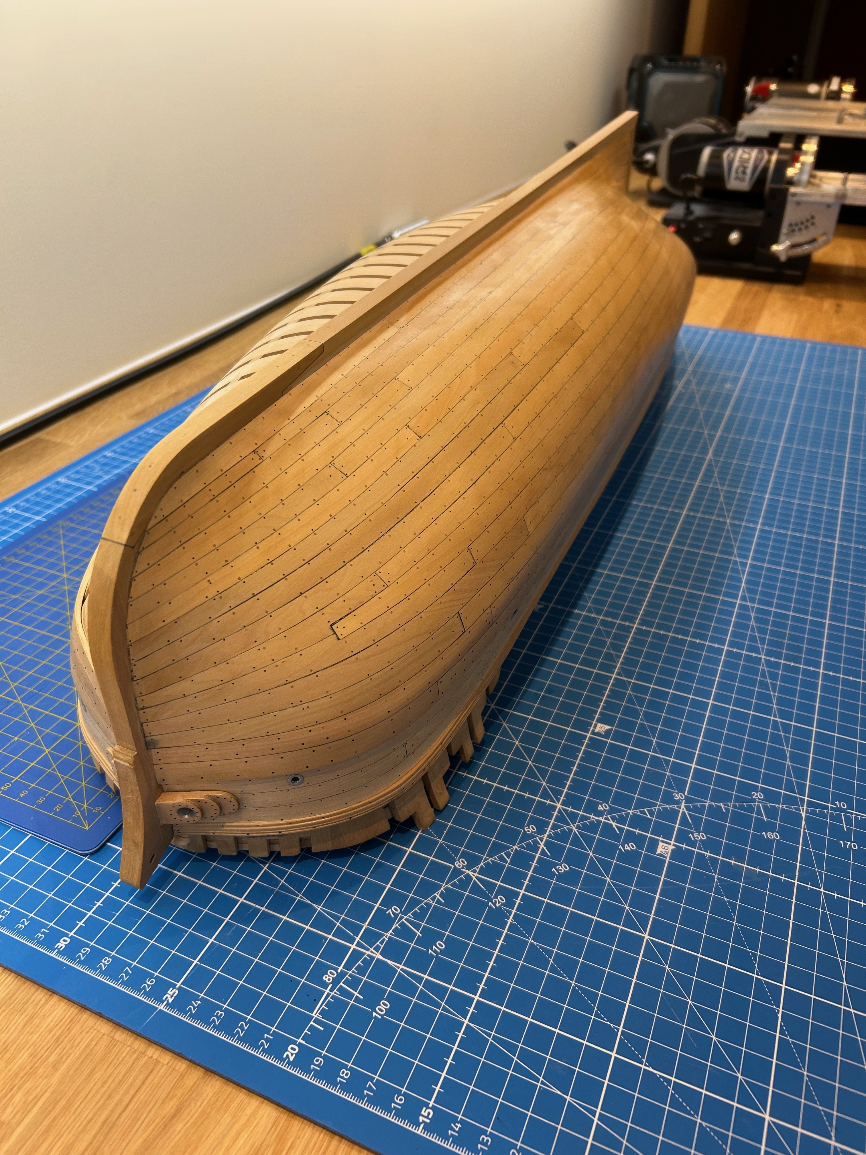
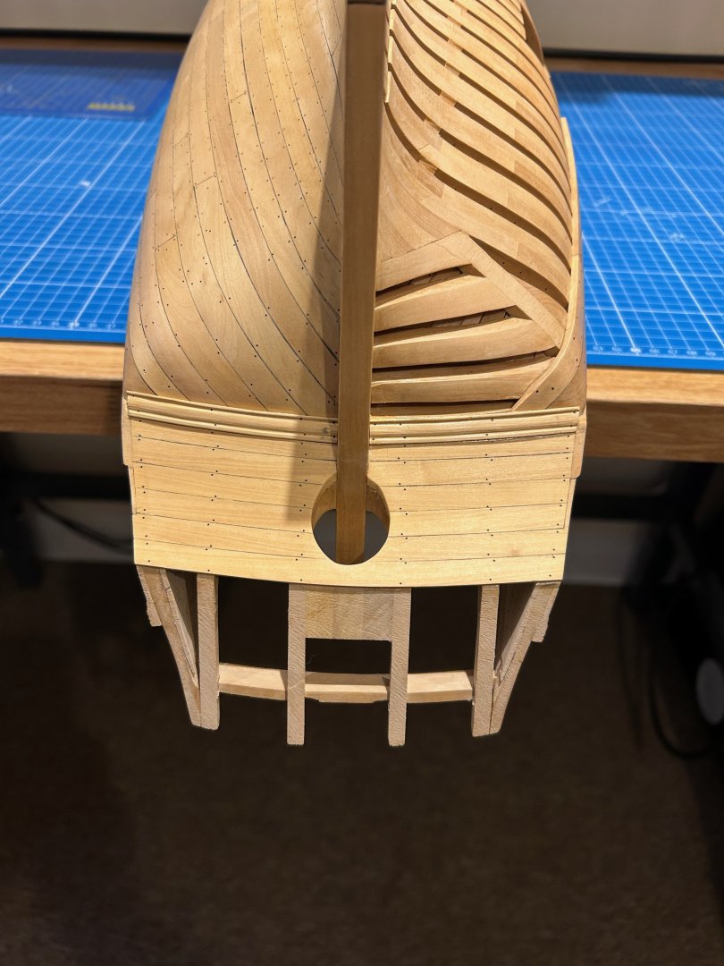
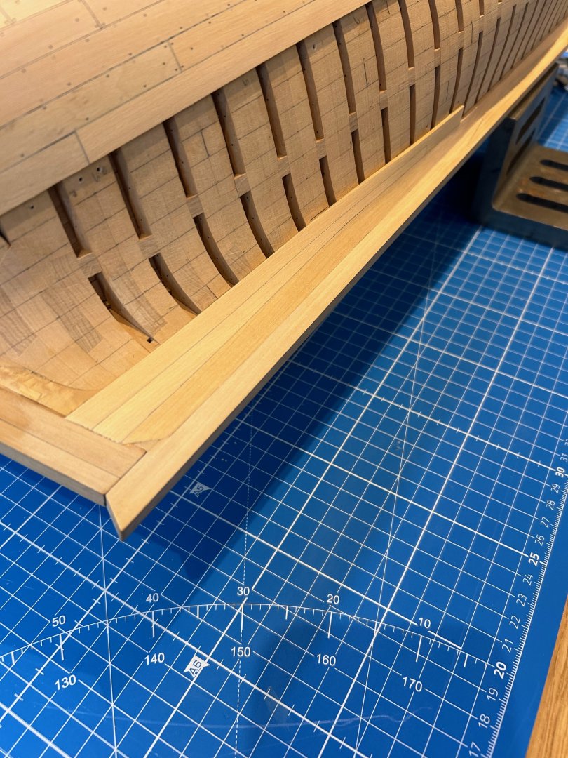
Thanks SaltyScot Thank you giampieroricci Cheers CiscoH Cheers davec 👍 A little bit more of an update - Today I tackled the limber channel which I've been putting off since I completed the frame work. To me its one of those jobs that you only get one go at and its nerve racking!!!! I also gave it a real good clean up inside and out and finished the port side with the same shellac I also repaired the damage to the counter timbers so they are now fine again My next job is going to be planking the stern vault - The timbers have a shiplap joint and I have already cut them and are good to go. Thanks for re-following my build and honestly thanks for the kind comments - Mark


-
Thanks Kevin - This is the first time that I have single planked a hull as my others have been double planked. Its Ok but I've learnt a lot doing this - my next build will be better Thanks Chris - I think it was Chuck or Dan Vadas that put me in the direction of shellac. I found that I prefer the finish of the sanding sealer rather than the shellac gloss itself. It's easily removed if you get it wrong and it's, its own solvent too. I apply it with a French polishers cloth bulb and immediately rub it over with a cloth. This removes any excess and matts it down too. I buy it ready mixed from these people https://finneyswoodfinishes.co.uk/Finney's_Shellac_Sanding_Sealer. I have brush too that I use and I don't bother cleaning it after use - Just drop it into the shellac and 10 minutes later the bristles are soft again. Cheers mate
-
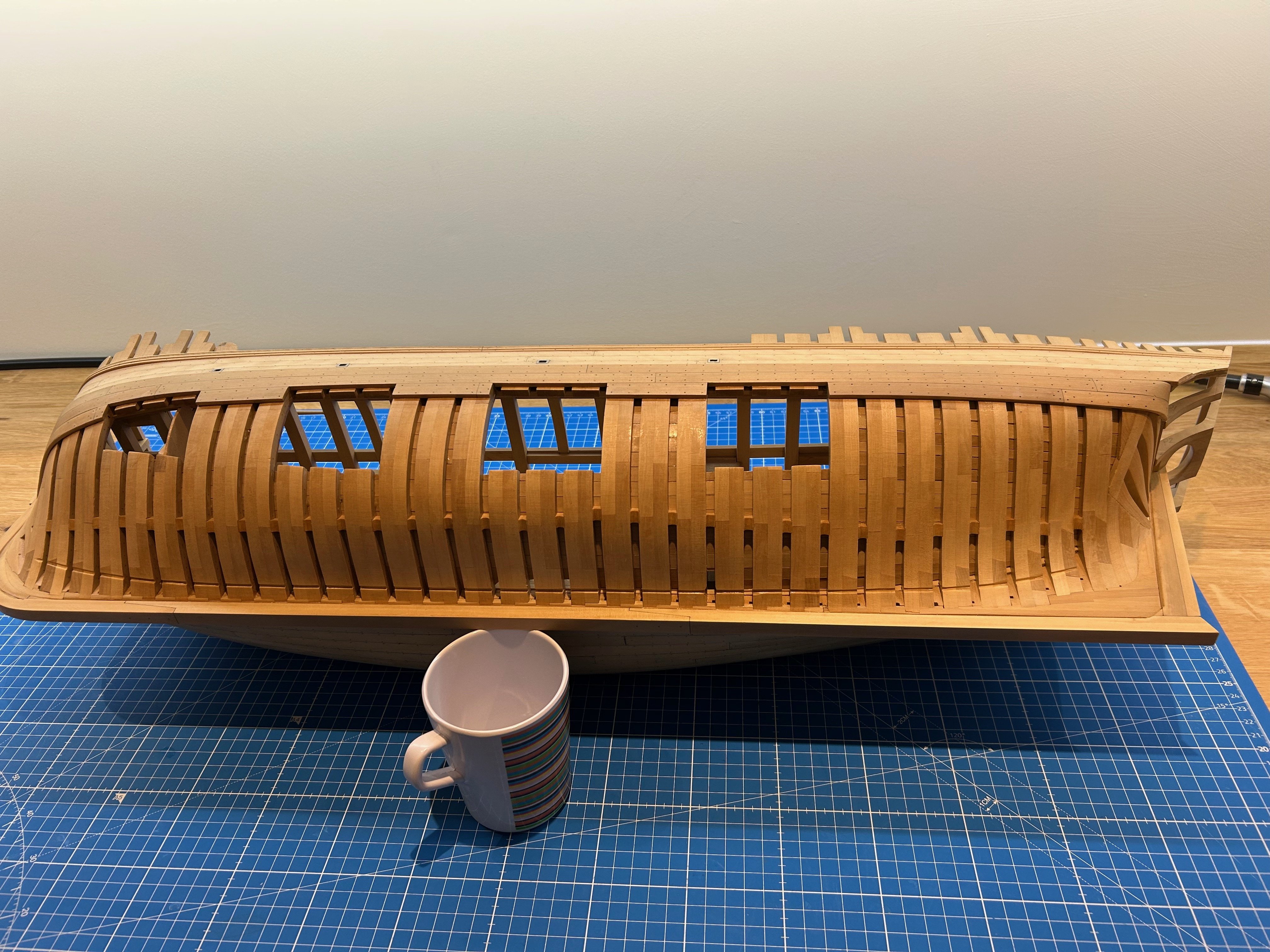
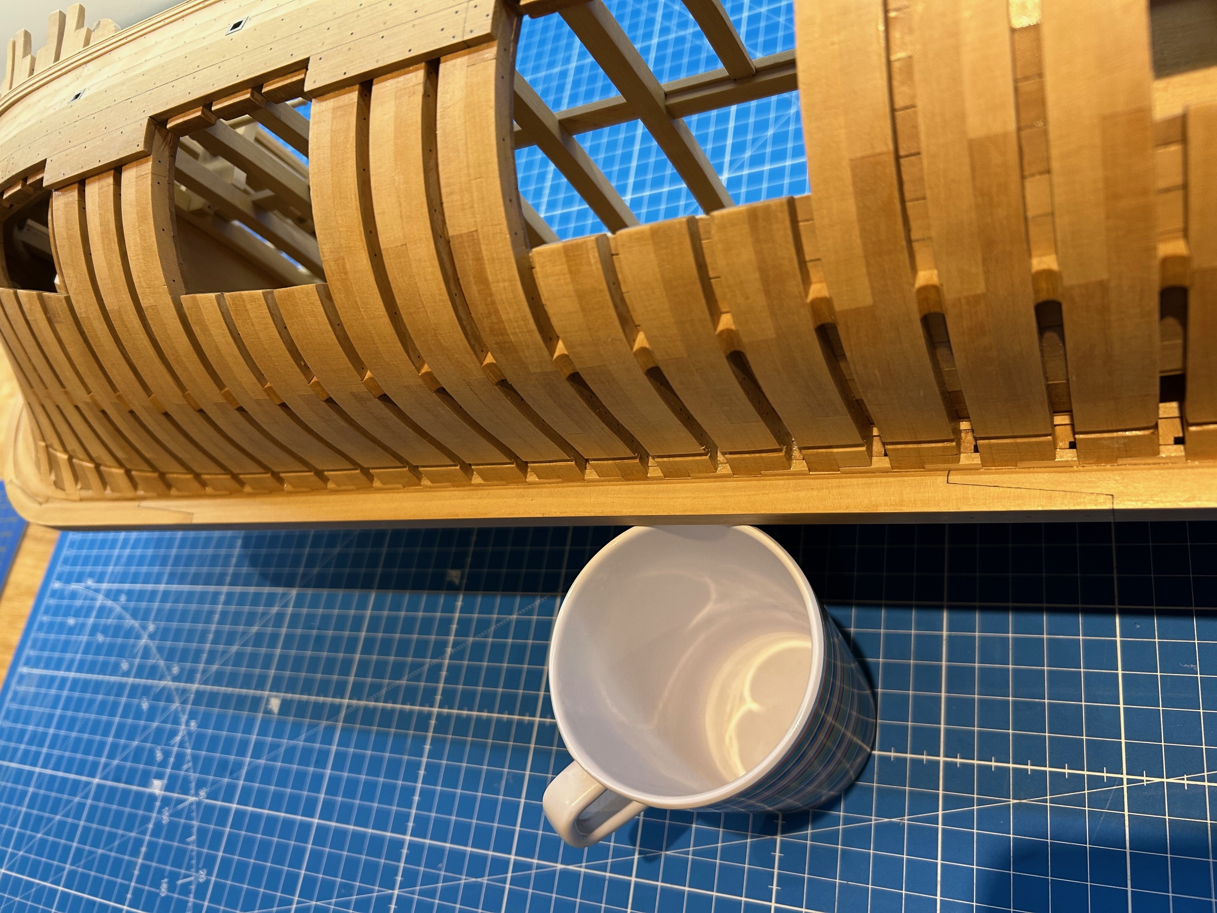
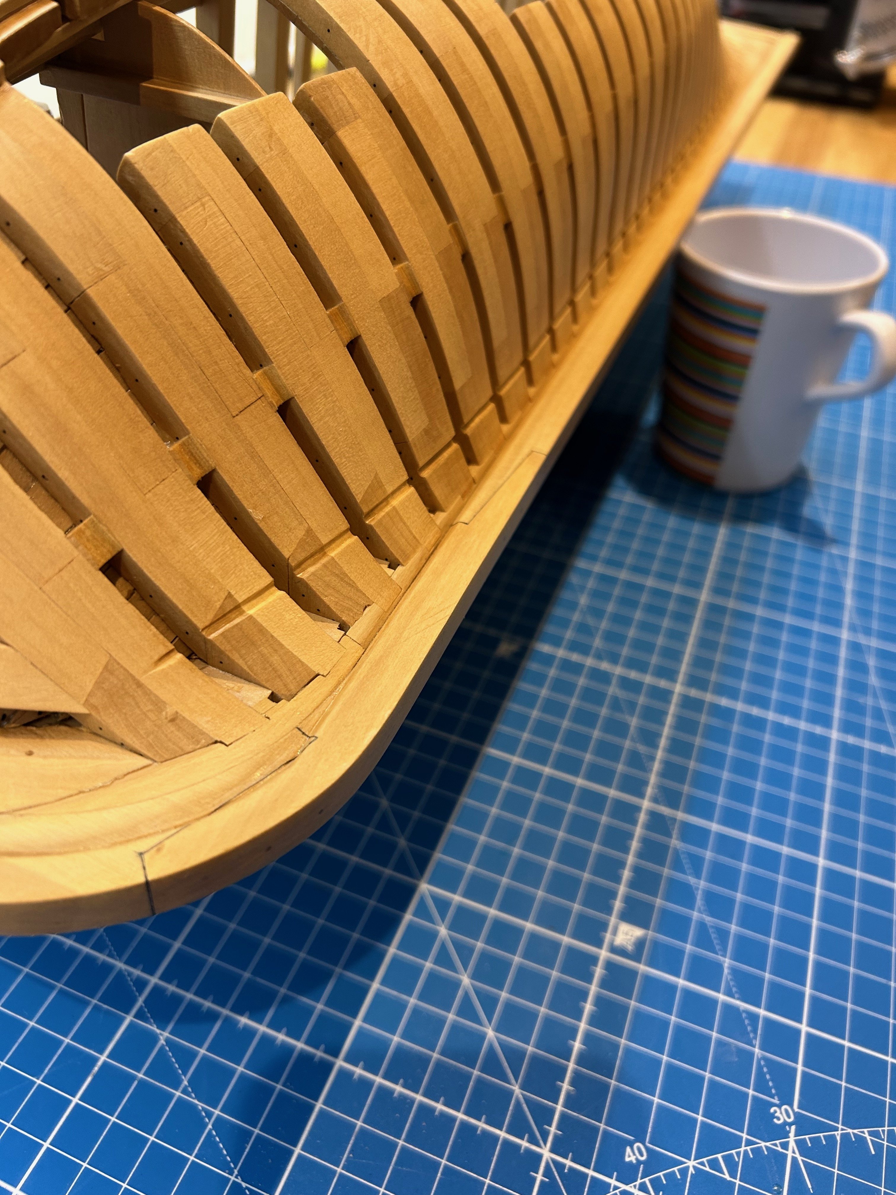
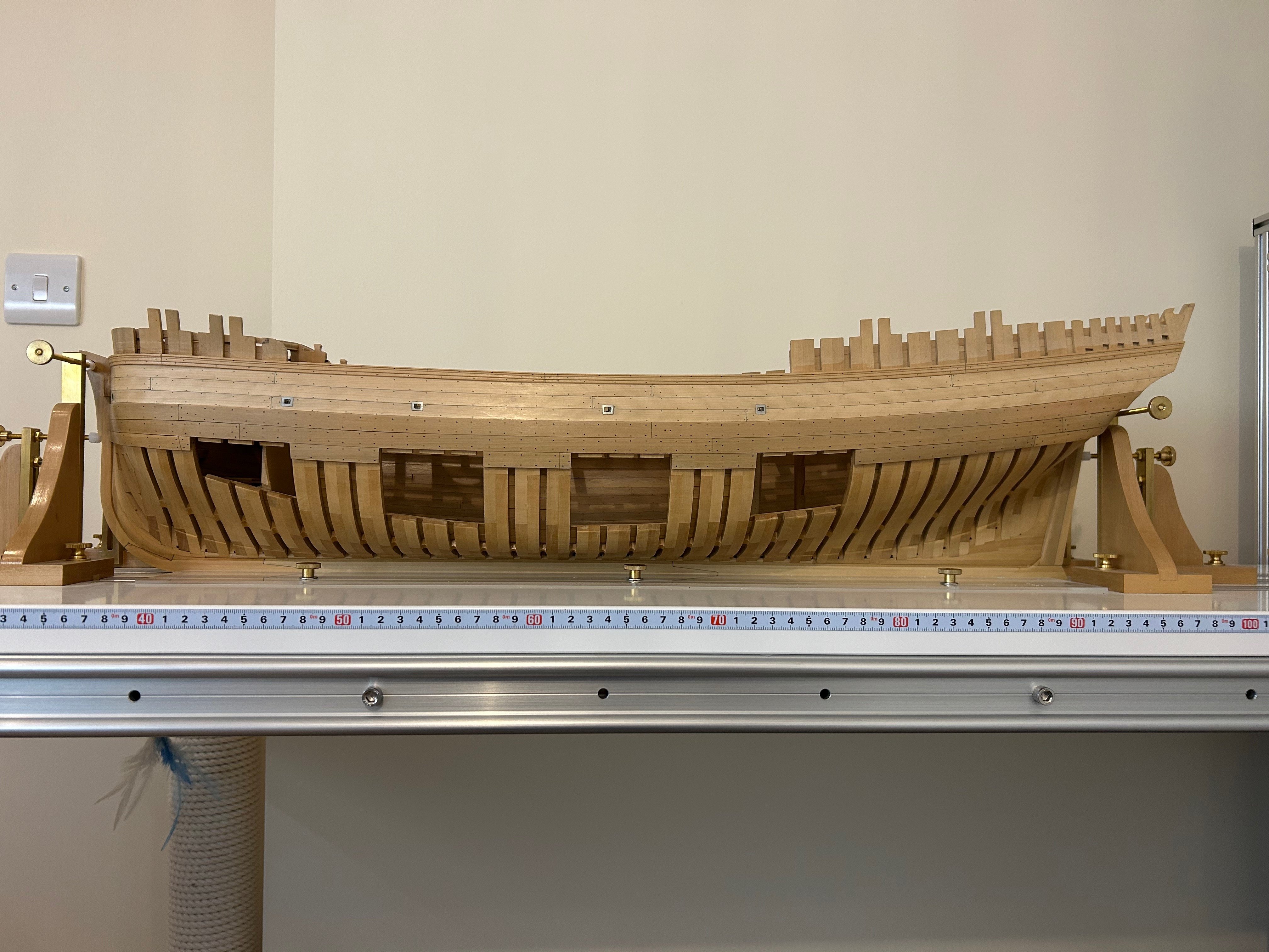
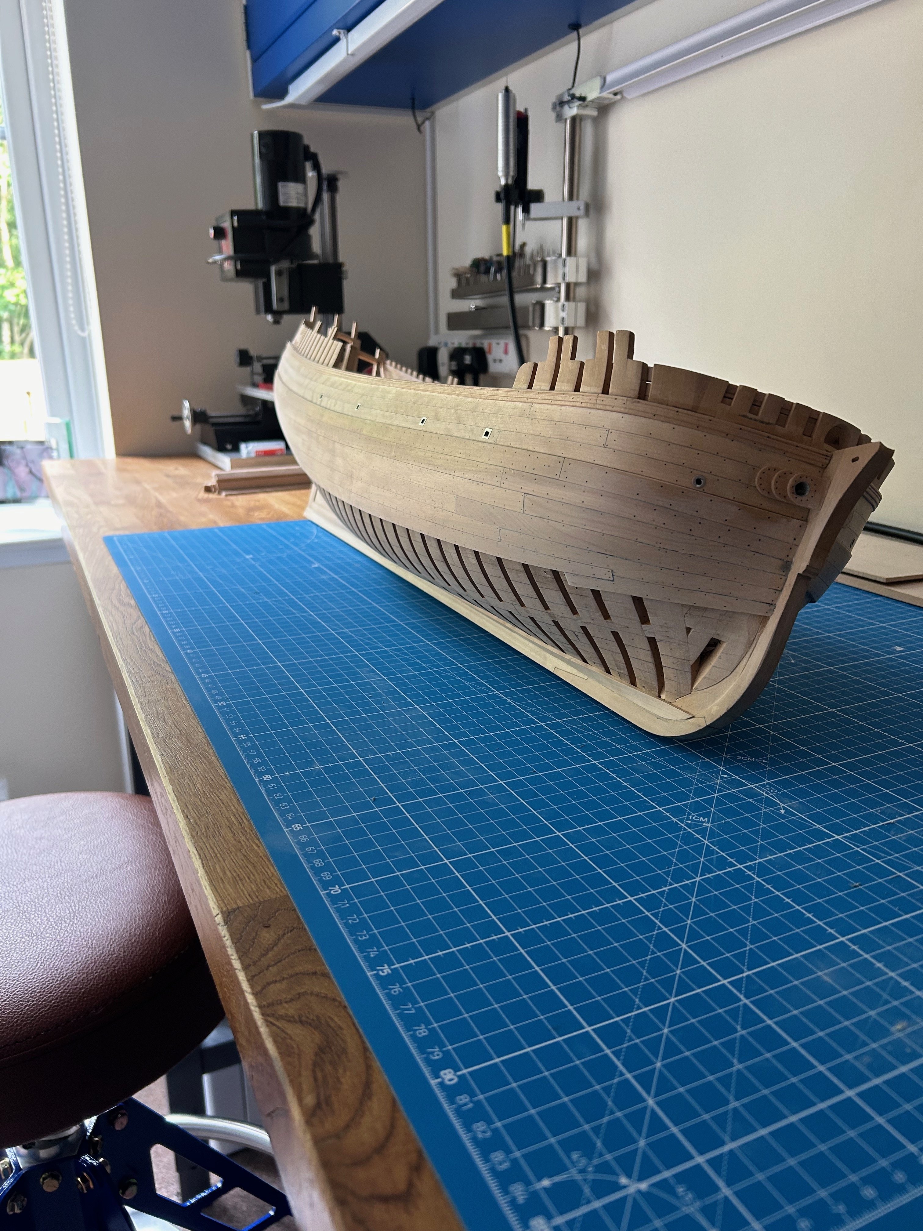
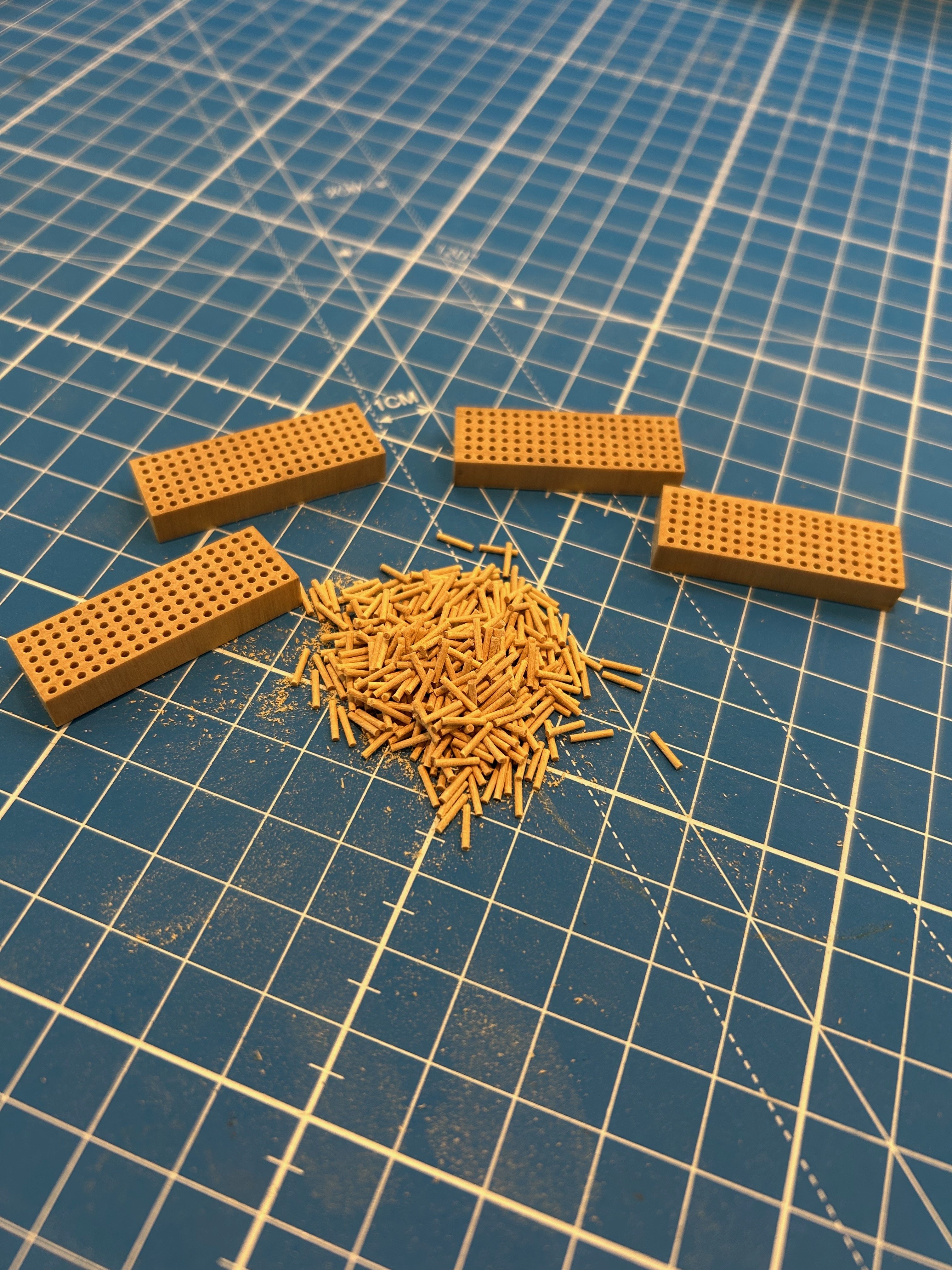
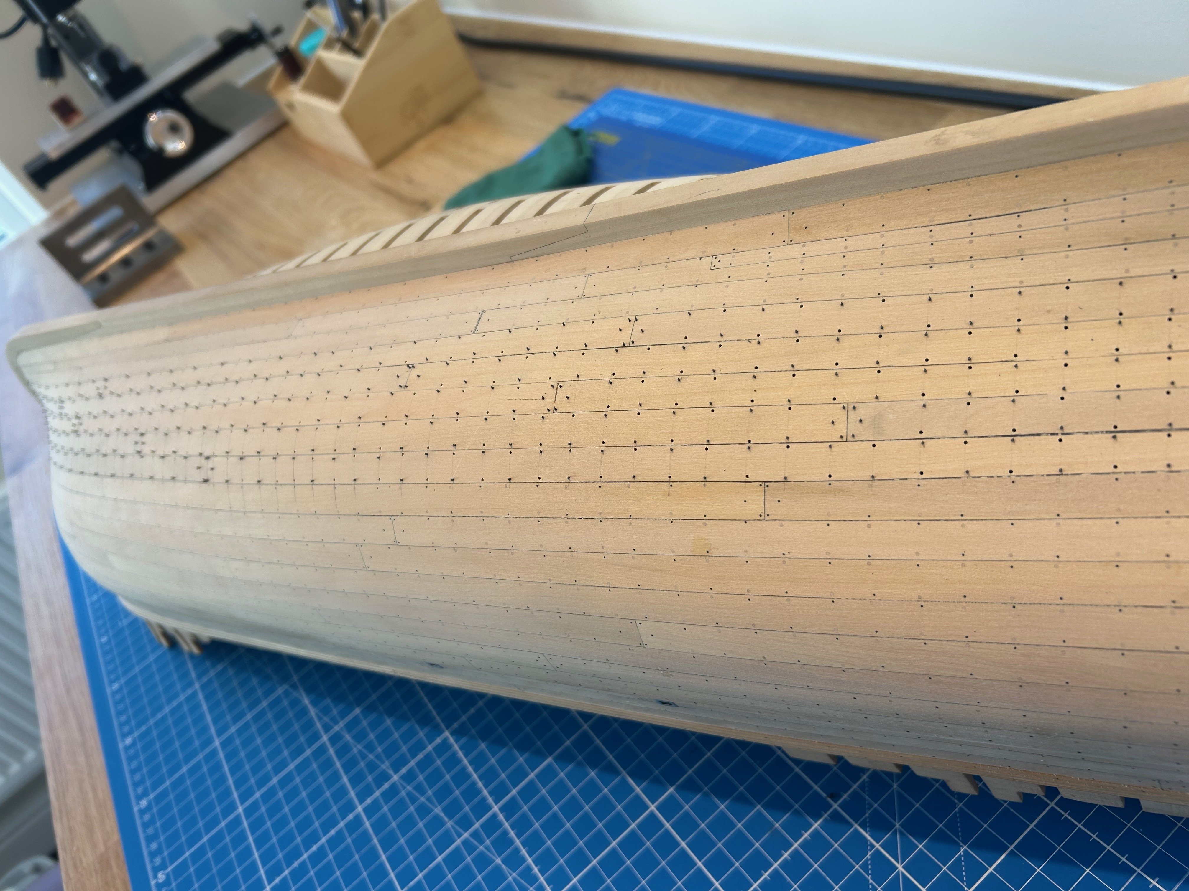
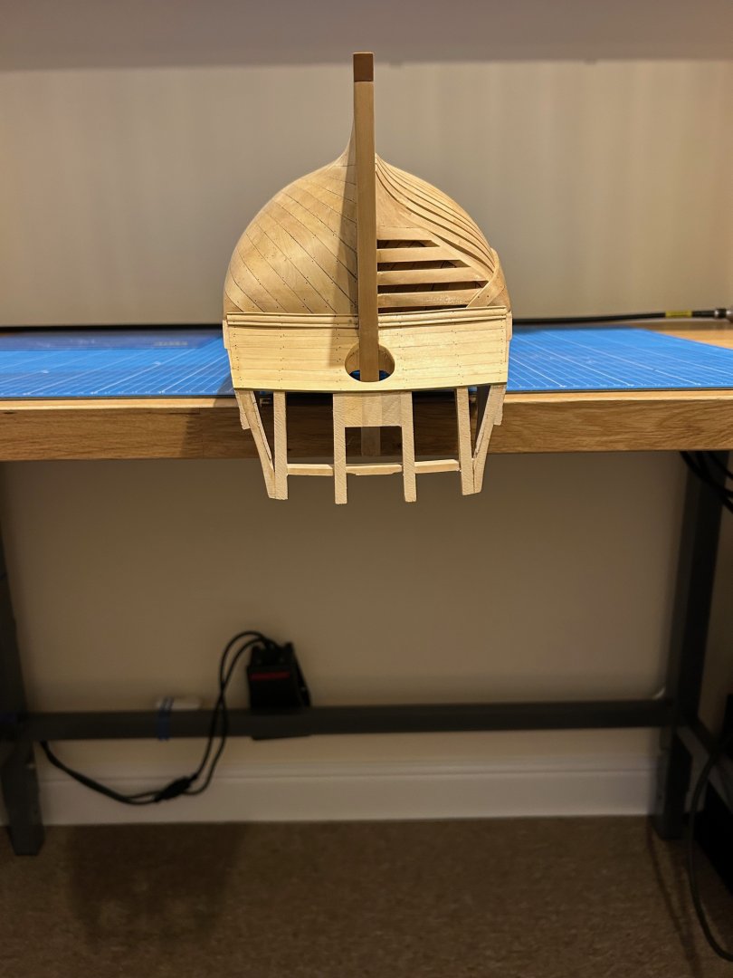
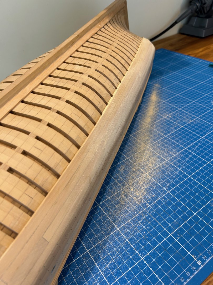
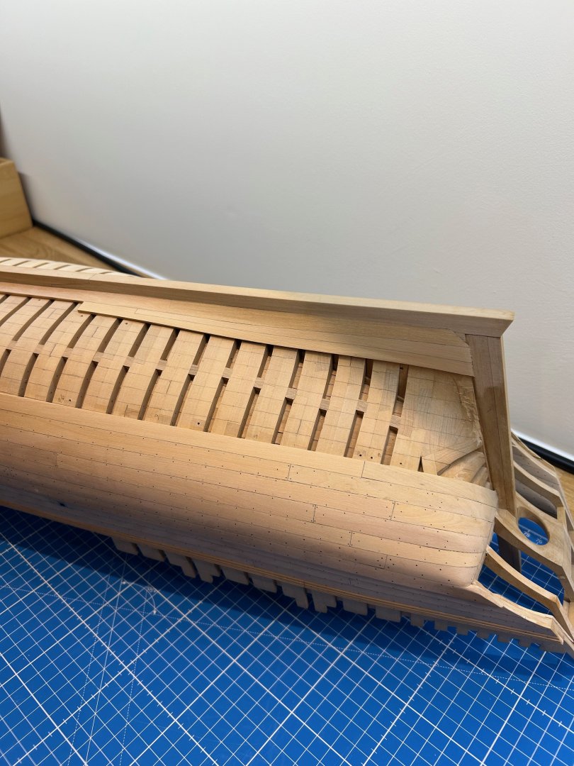
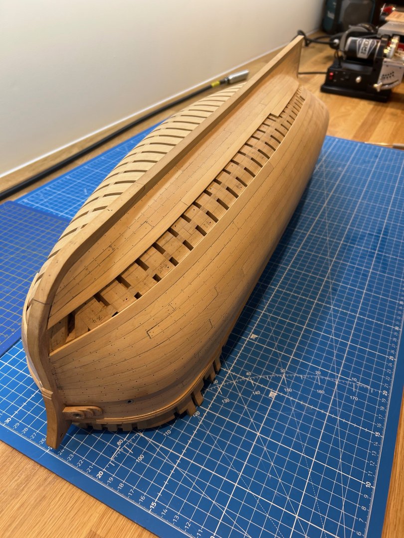
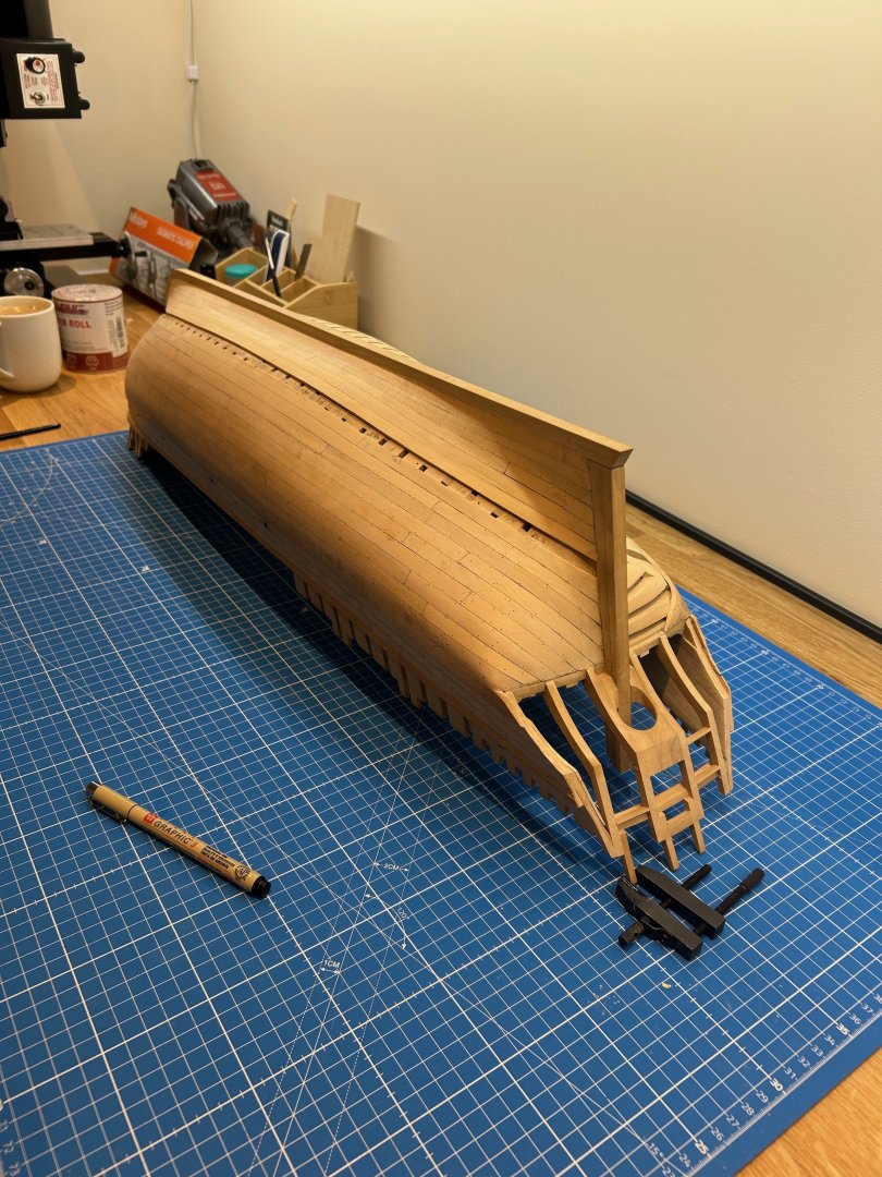
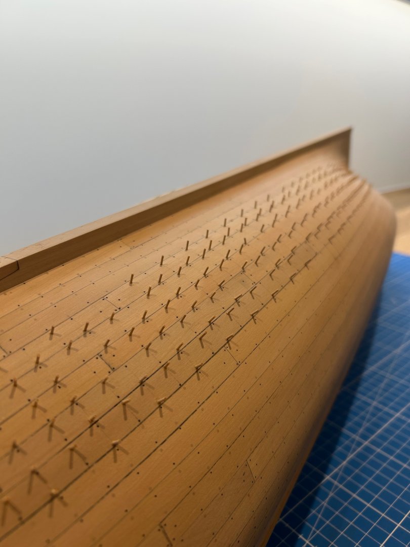
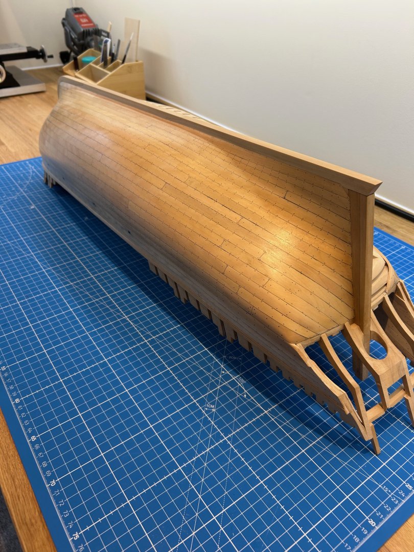
Well after a very long wait for me I eventually got my workshop back in November. I did however revamp it with a bigger work area and decorate it too. So back to building Le Rochefort at very long last! In my last post I had to remove a few planks and have a good clean up. Since then I've been happily getting the planking done. I think the comments above sum up the issues I had so I think pictures tell a better story than words. More tree nails Final sanding a a very light coat of shellac sanding sealing Some of my joints leave quite a bit to be desired but on the whole I think it looks OK. I could have made life so much easier by using much thinner planks but I wanted to stay true to the drawings and scantlings. Next time I will not use black archival ink for the joints either as I think it just looks far too stark. I would probably use brown ink or just a HB pencil as my dodgy joints would not stand out so much! I've learnt how to spile planks now too and I have found that once you get your head around it the process is very easy to do. The ship has sustained a bit of damage in the process and as such I need to repair the counter timbers a little and remake the taff rail stantions. Its no big deal - I think it was druxey who a long time ago said that they probably wouldn't last the distance during the build - he was right 🤣 I wanted to remake them anyway as I had missed out the detail on them which would have been difficult to do in place. The new and improved taff rail stantions which I knock out earlier on the mill So thats me back at it and although I've been participating on the forum there's nothing like actually building My next jobs are to cut the limber channel and shape all of the frame spacers on the port side. I'm then going to concentrate on the stern just to beef it up a bit as it's too exposed at the moment. Another job is going to I'm going to make a heavy duty keel clamp. I didn't enjoy chasing the hull around the work bench and I've seen that others have made one too. Thanks for your patience - Mark


-
You could always buy a Foredom pendant motor which is an amazing stand alone tool for modelling and then also get the drill press attachment which is extremely good. Two tools in one but they do not come cheap but will last a lifetime.
- 53 replies
-
- 3
-
-
- Drill Press
- Milling
- (and 1 more)
-
Thats a fine looking model you are building there Chris
-
Such a beautiful build and yea it is a work of art!
- 399 replies
-
- 3
-
-
- winchelsea
- Syren Ship Model Company
- (and 1 more)
-
Sorry all I should have replied sooner. I would like to thank Gerard as I have now been contacted by Ancre and they have been very helpful. I guess we are all busy people but Ancre have really stepped up for me and I cannot thank them enough. A very unique and niche company that supply the very best monographs. Cheers Ancre
-
Hi Seawatch and happy new year Any idea when you will be printing the physical copies of the TTFM books in 2025?
-
Fantastic build! Regarding the fairing of the rear frames I personally removed most of the material before installing them on the rising wood. I think your question is a personal choice I just thought that it's easier to remove large quantities of wood off of the model rather than on it. However I have read builds where the builder does it completely the opposite way around.
-
Byrnes 18" extended table saw table
No Idea replied to davec's topic in Modeling tools and Workshop Equipment
In that case I would magnetise the screws so that they stay onto the screwdriver. That should sort your problem. -
Byrnes 18" extended table saw table
No Idea replied to davec's topic in Modeling tools and Workshop Equipment
I too changed my saw to a 18" table and I support all of what you say. Another benefit is that you can use the cross cut sledge without having to remove the fence. Just slide it out of the way. To fit the belt cover - the screws only need loosening and the cover slides rearwards and comes off. So if you remove your cover firstly put all of the screws into their locations on the saw but only loosely. Then place the cover over the belt and push forward towards the front of the machine. This locates it onto the screws and then you can tighten them fully through the access holes.

.jpeg.3a548be265ca065c6b76e58ecdcffad8.jpeg)