.jpg.f26acc9a74319261612561bfa7da1303.jpg)
vaddoc
-
Posts
1,605 -
Joined
-
Last visited
Content Type
Profiles
Forums
Gallery
Events
Everything posted by vaddoc
-
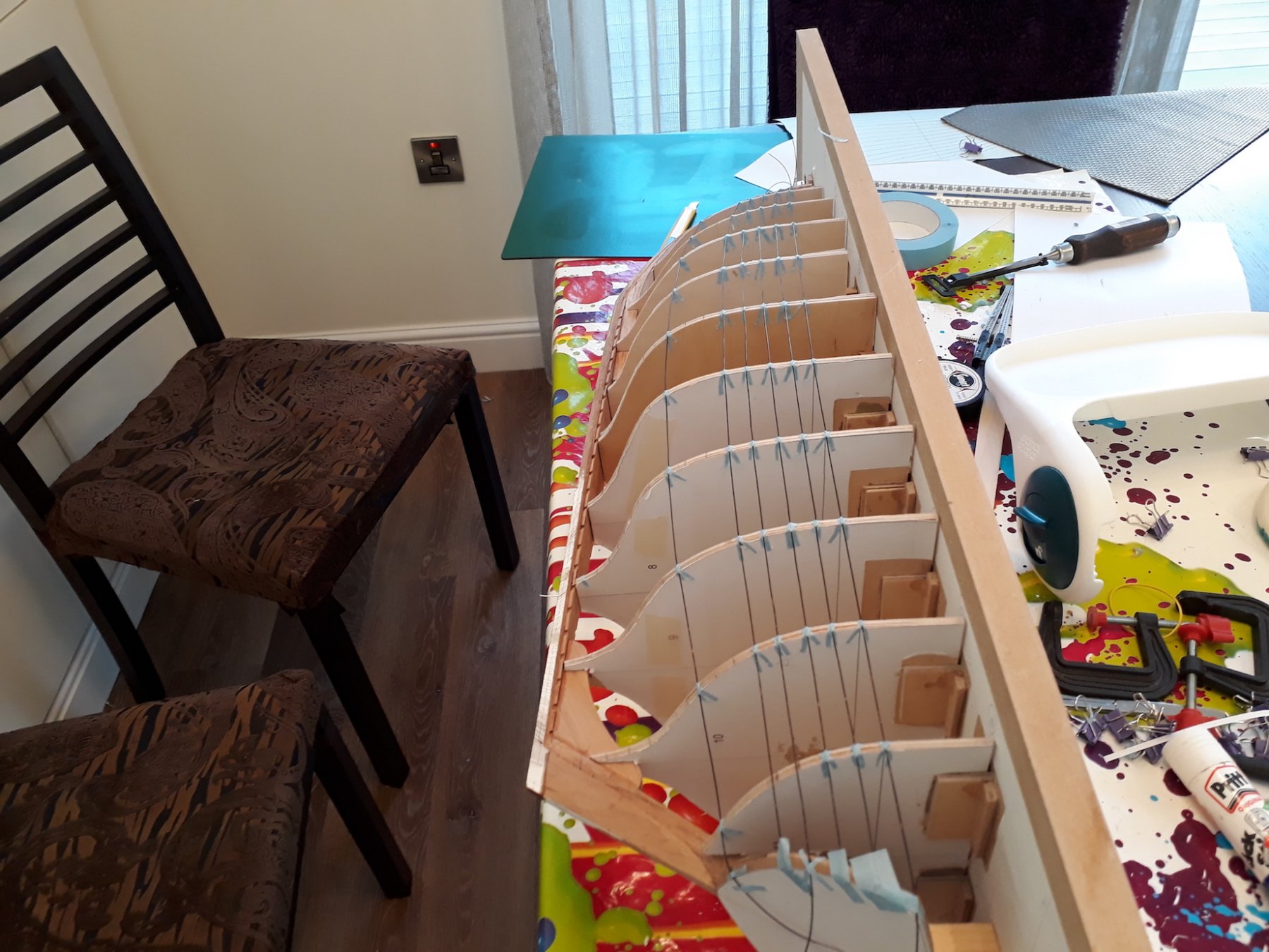
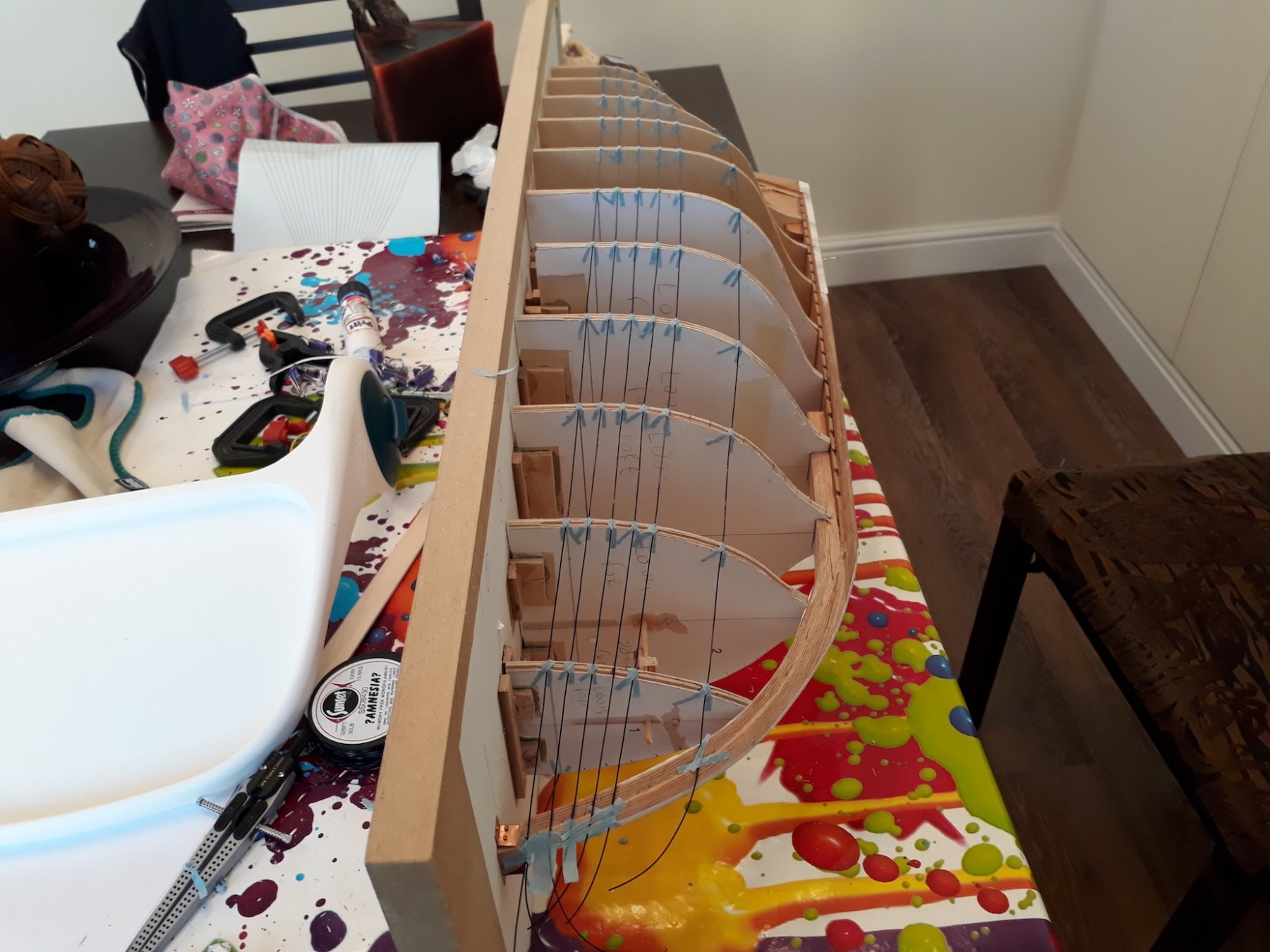
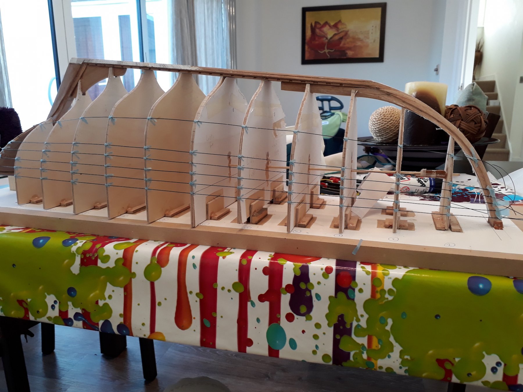
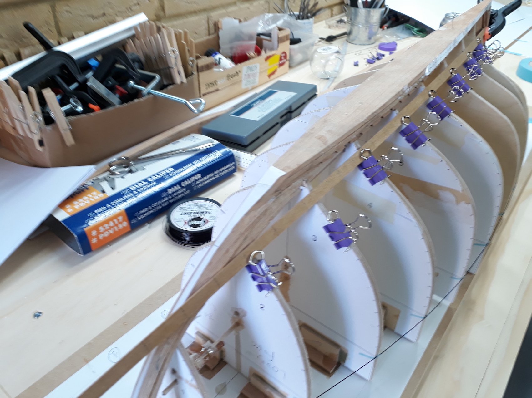
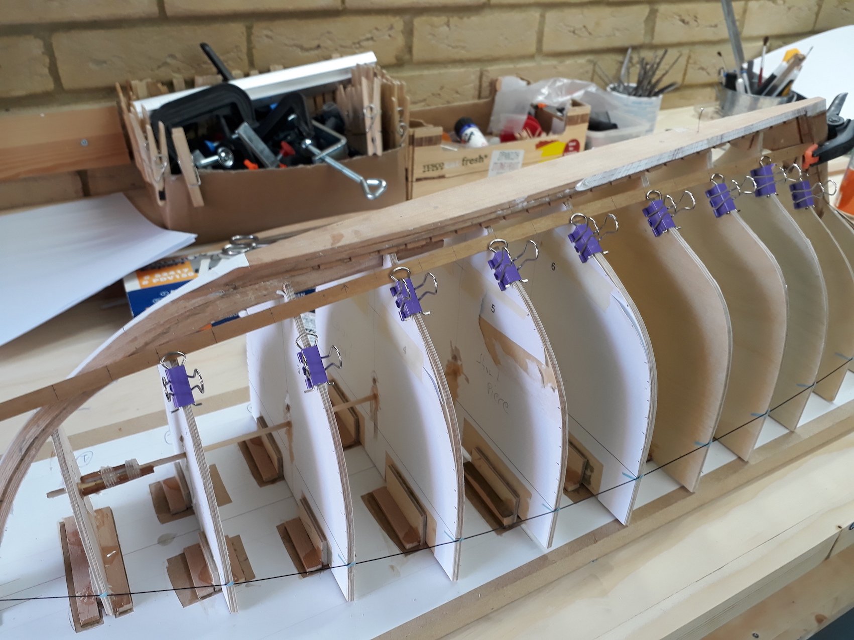
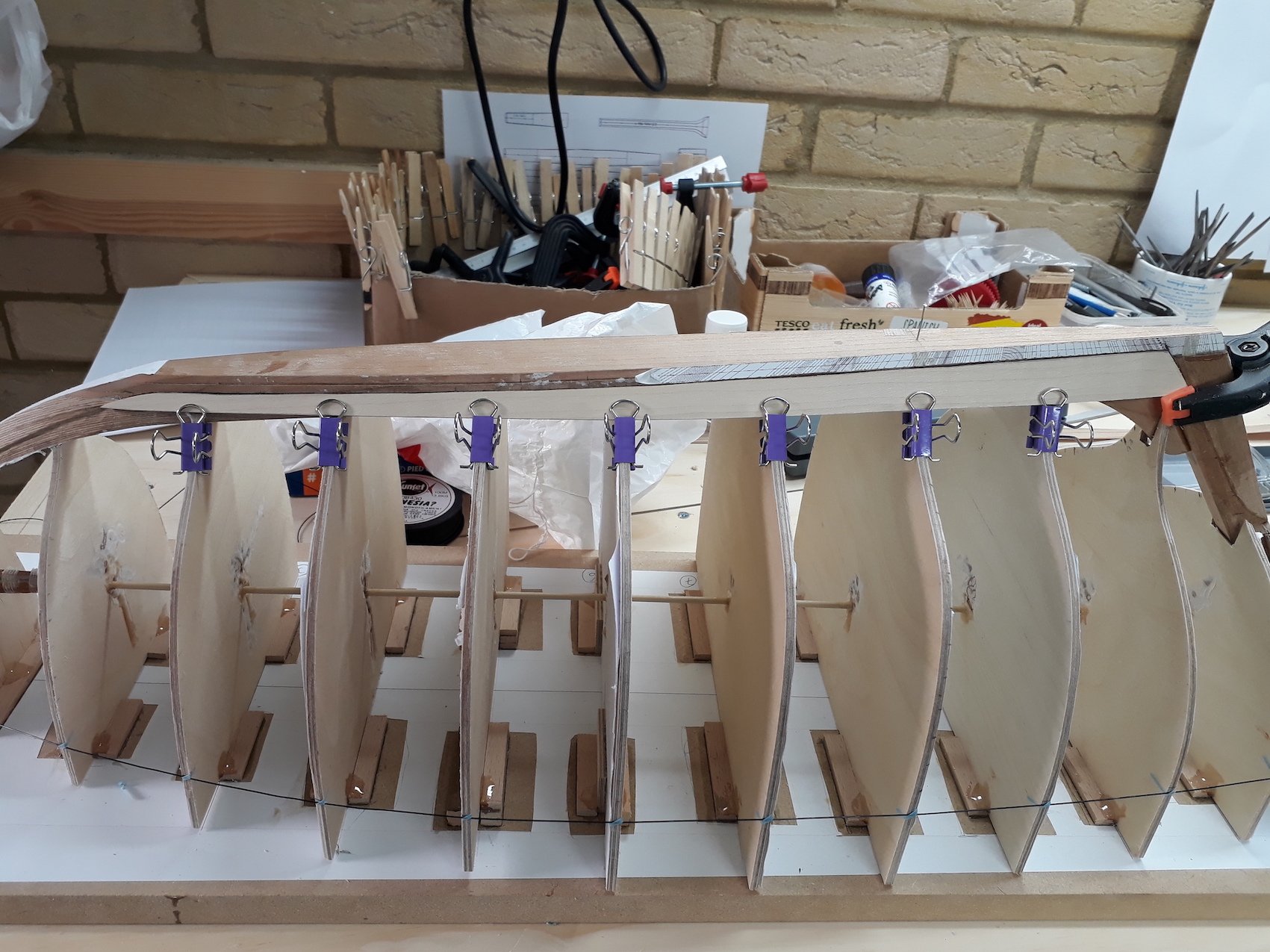
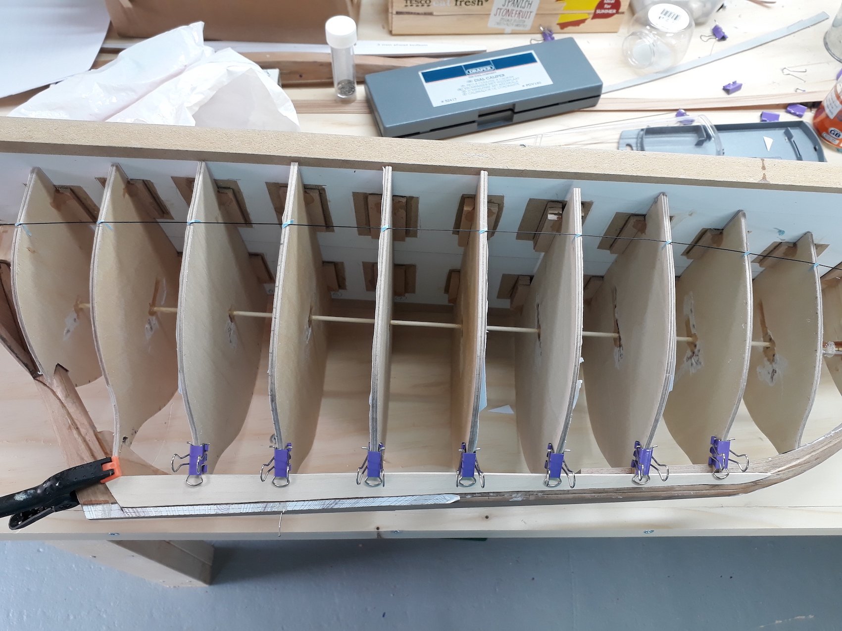
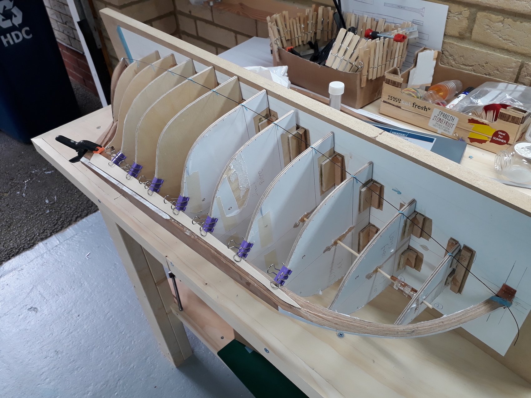
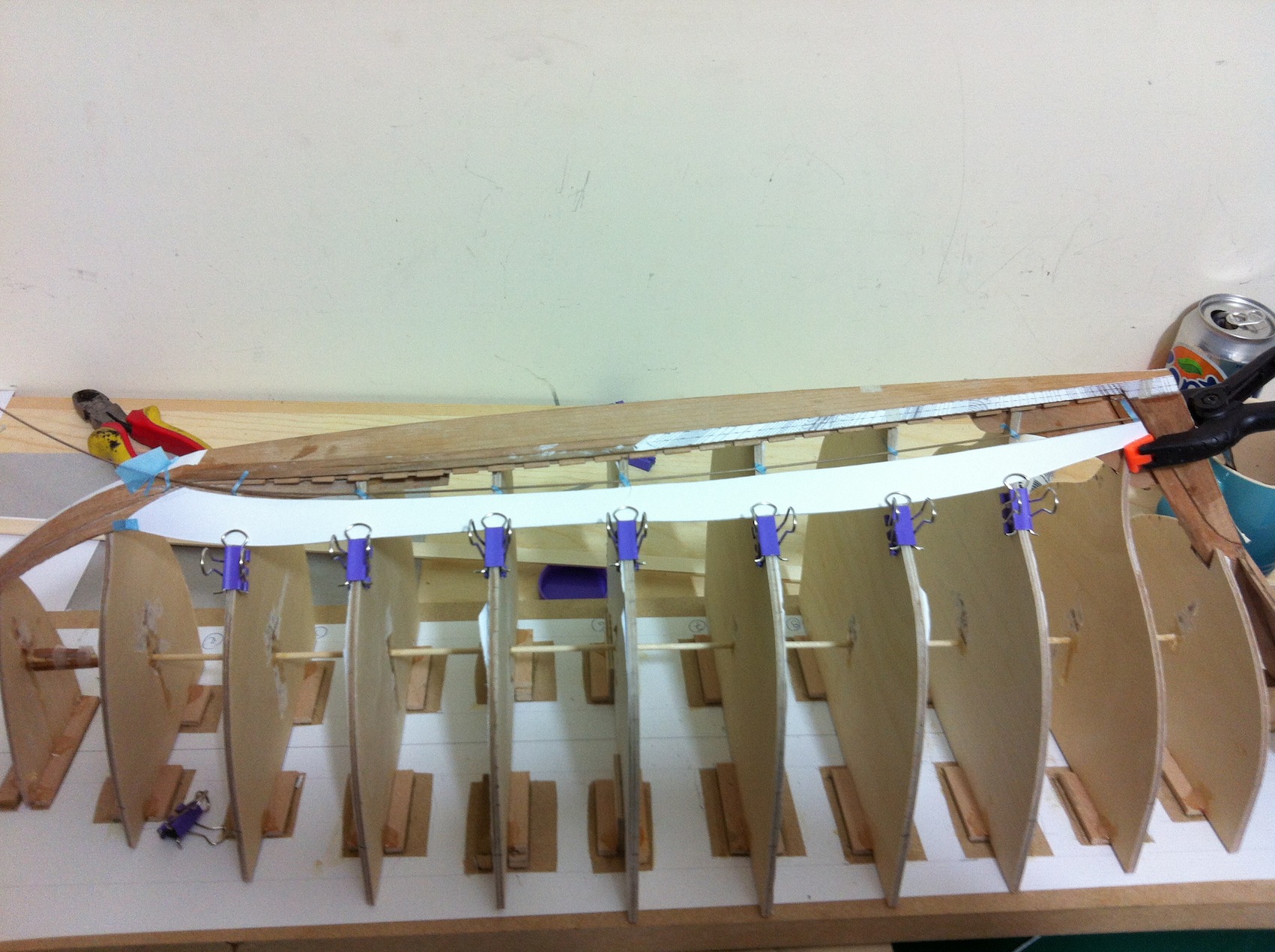
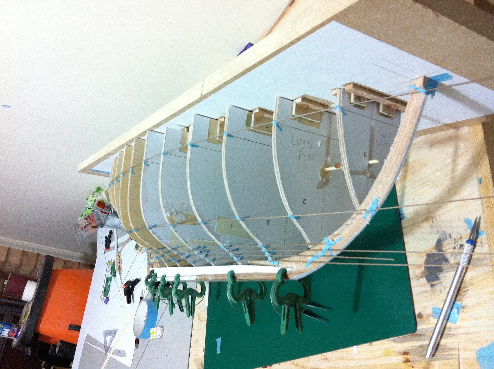
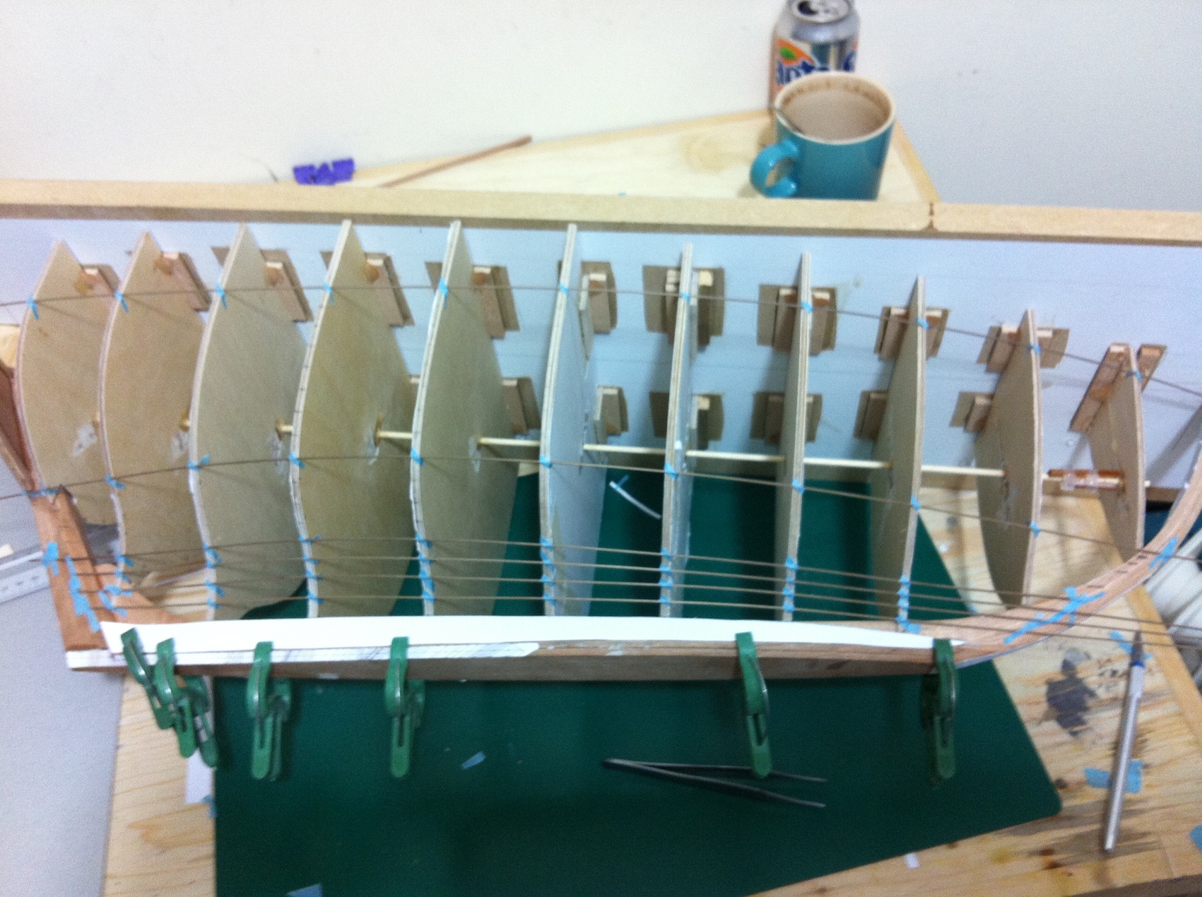
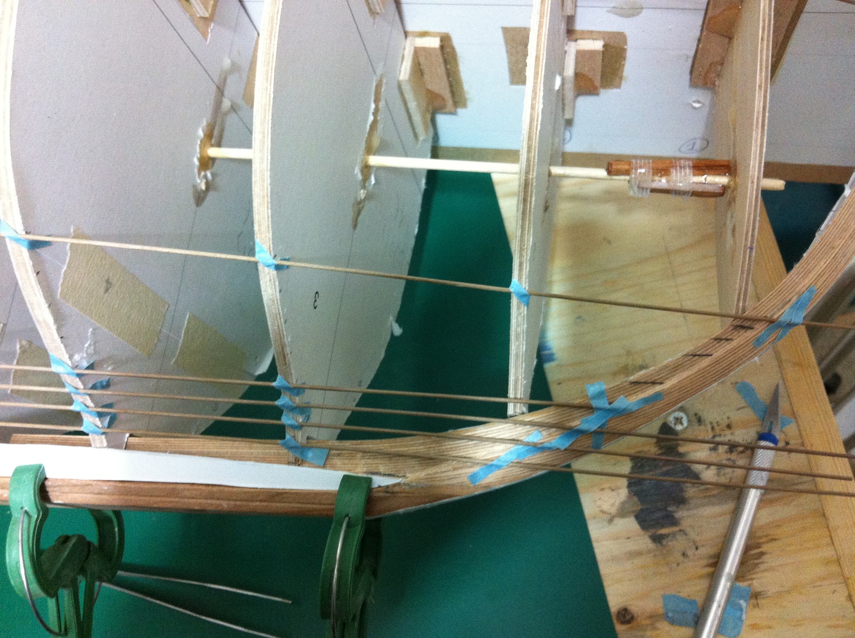
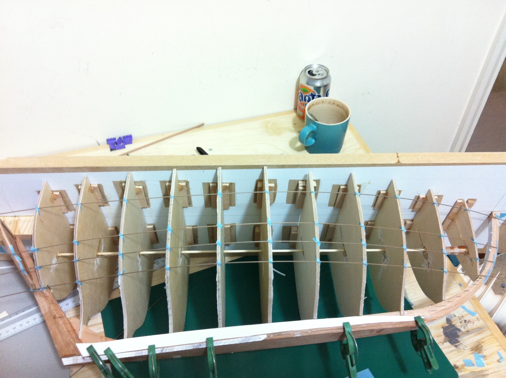
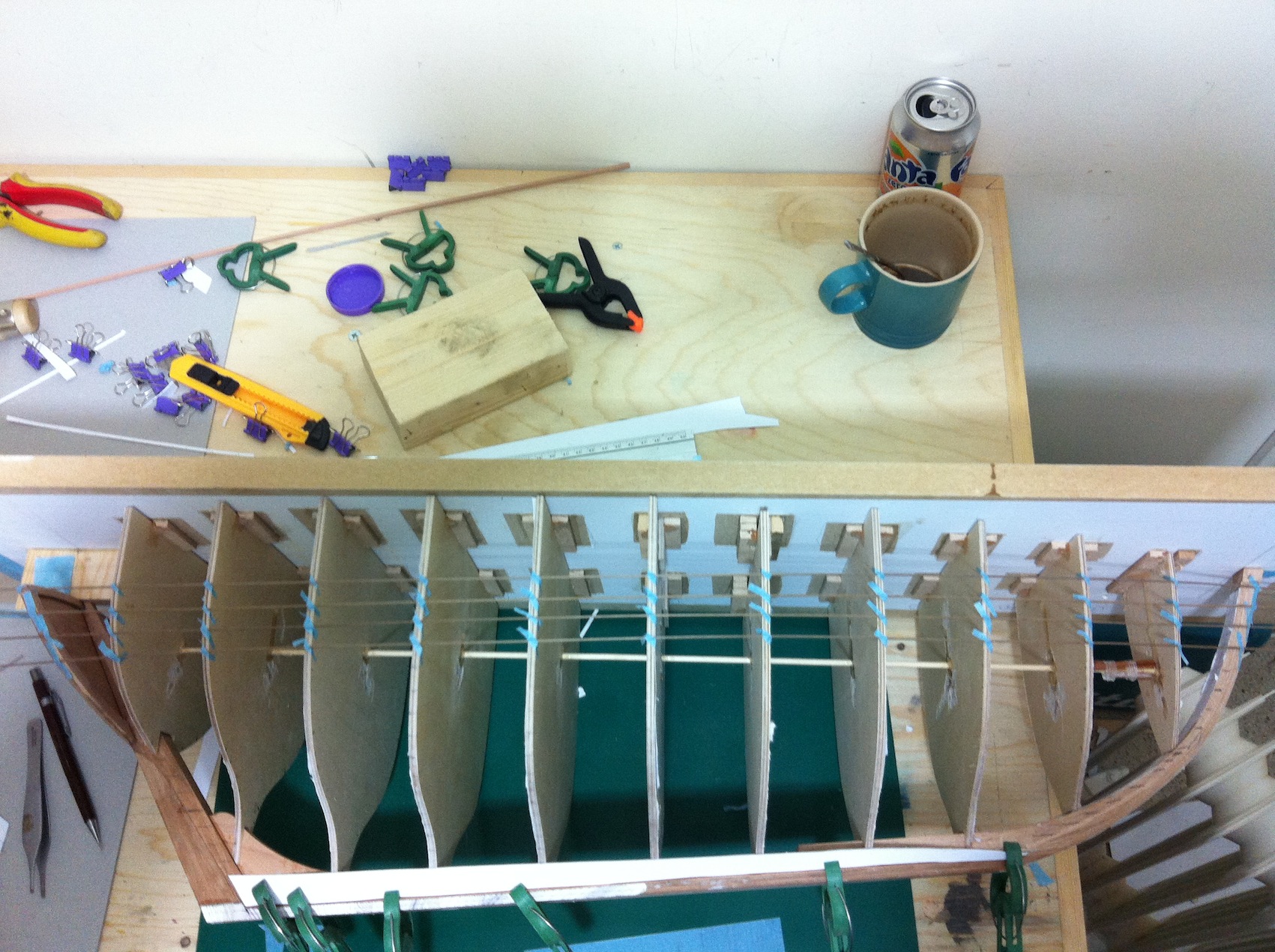
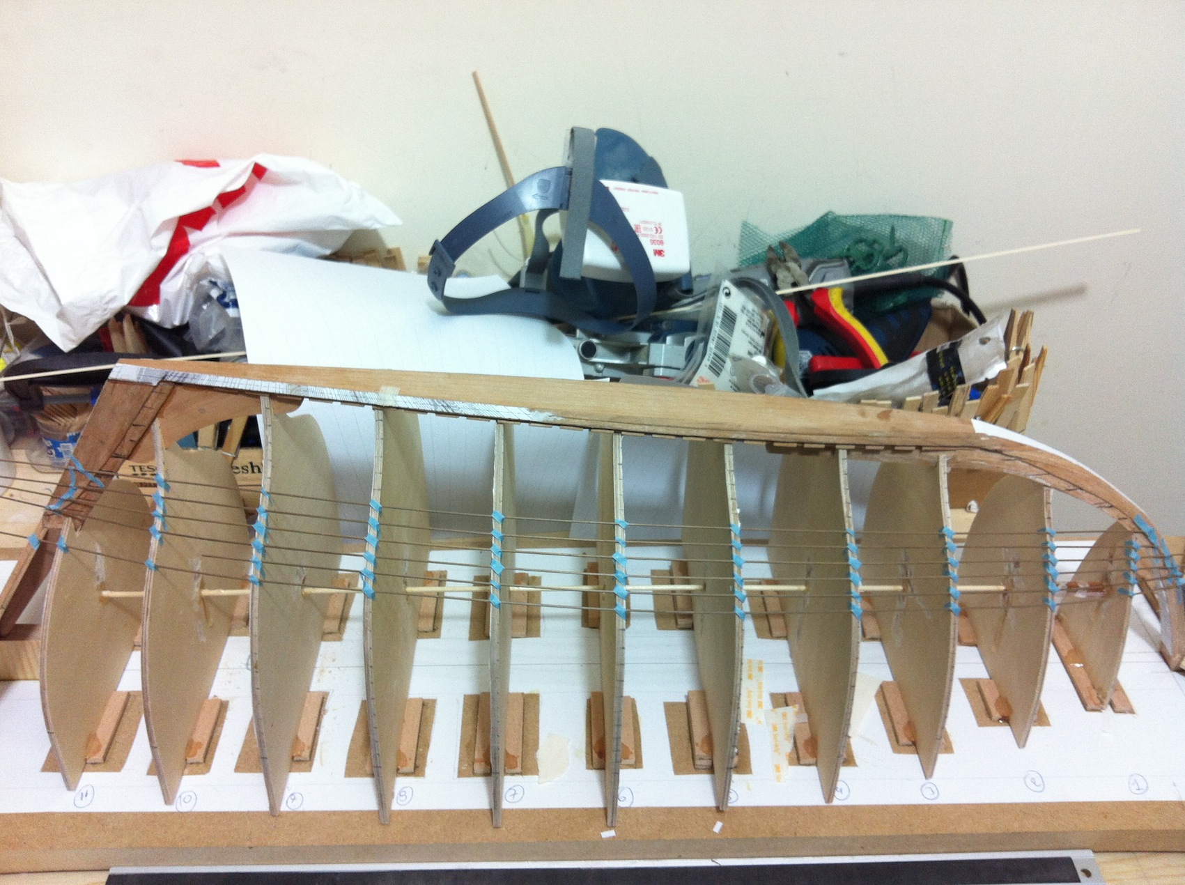
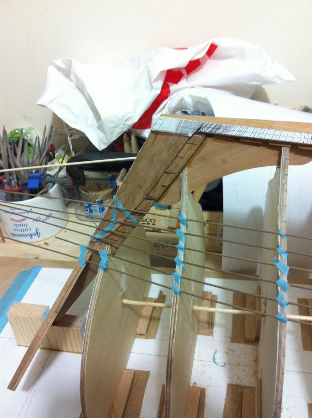
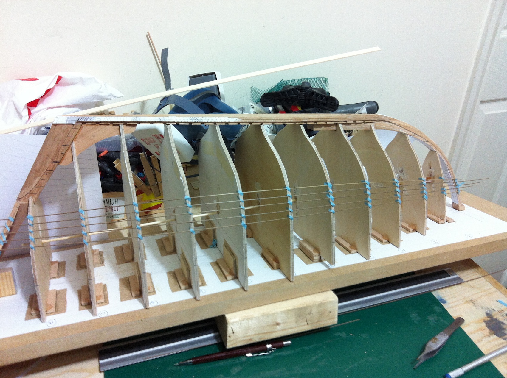
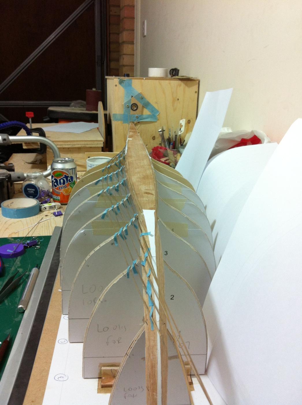
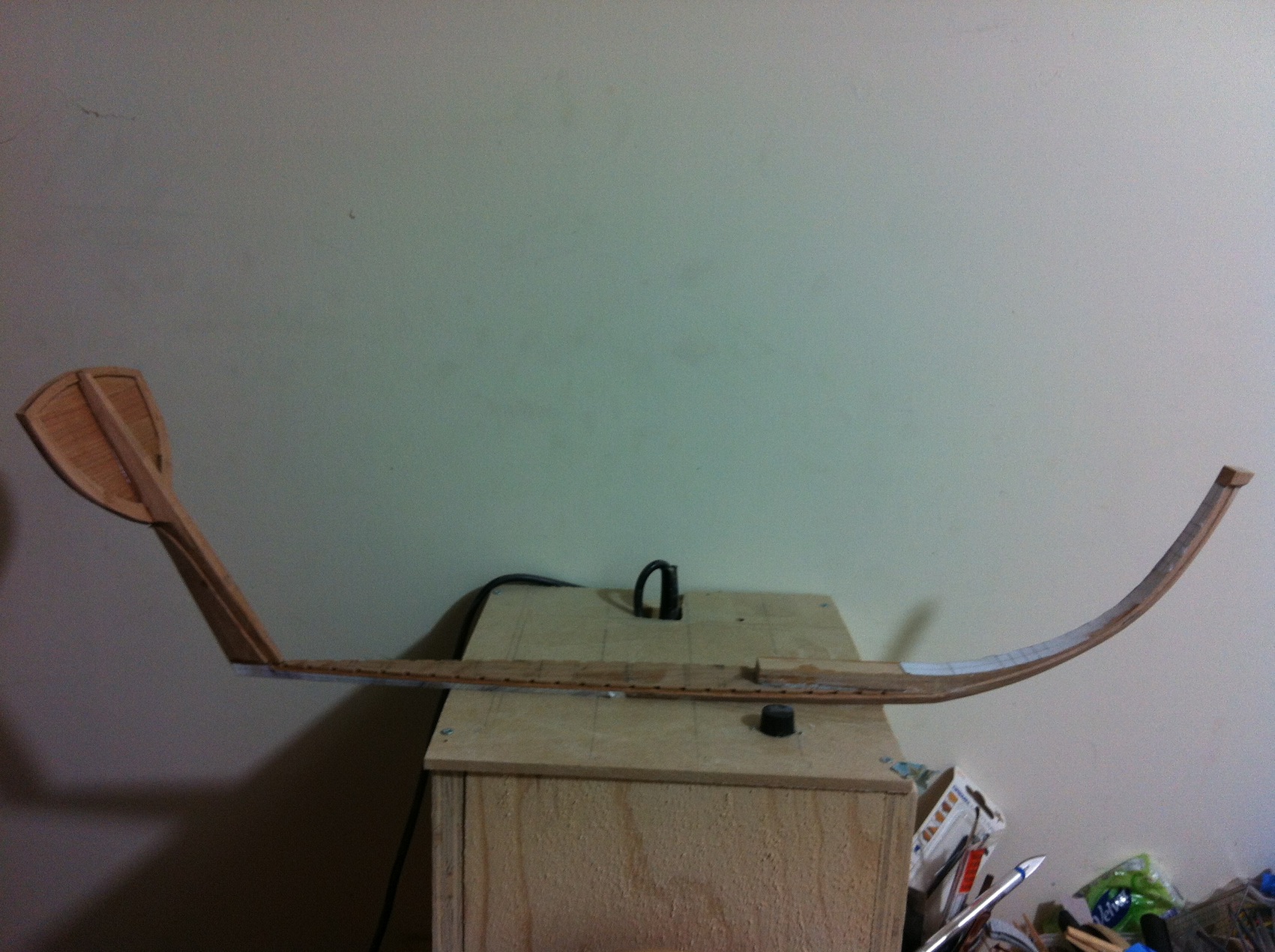
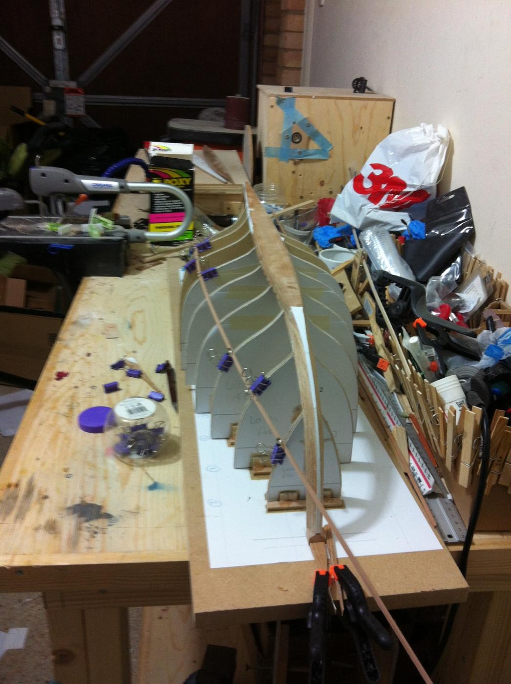
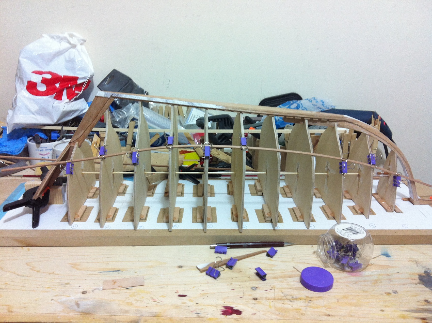
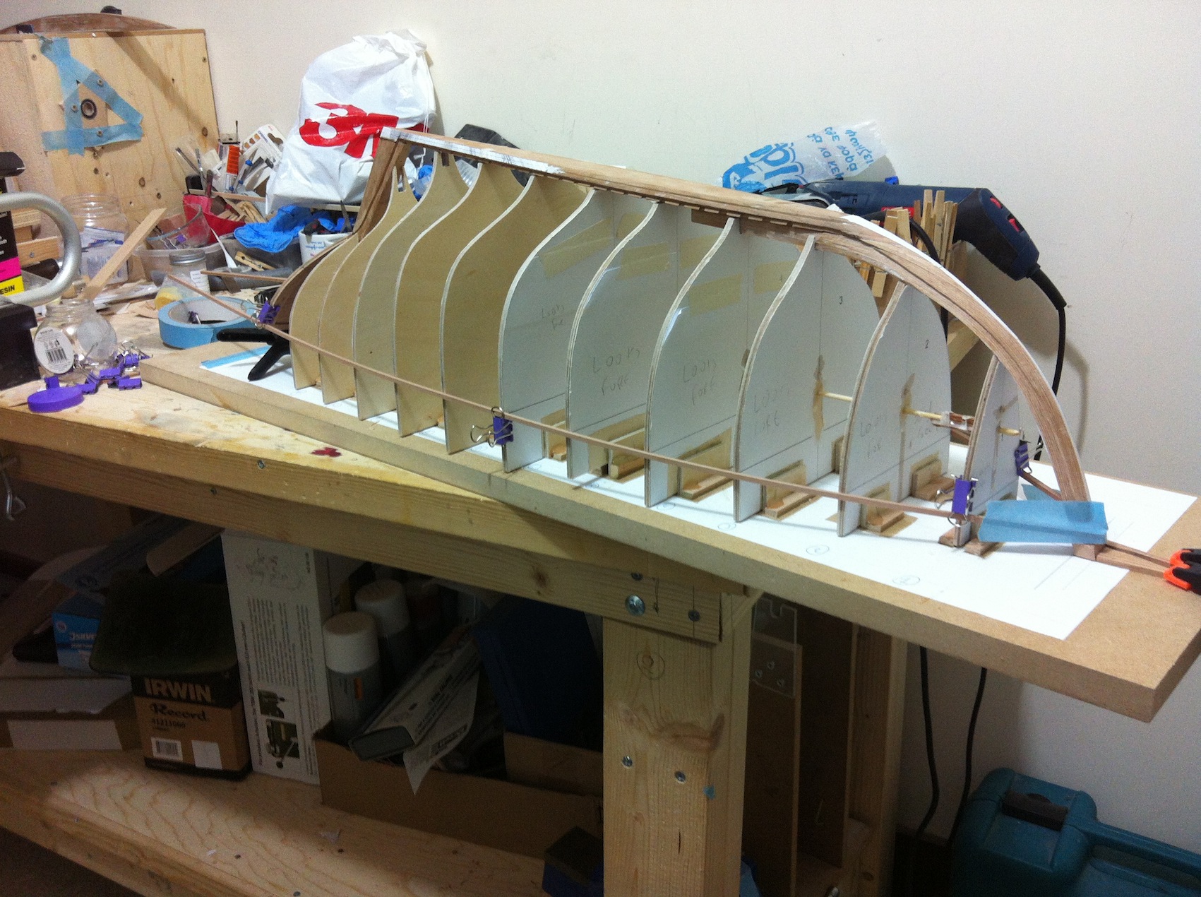
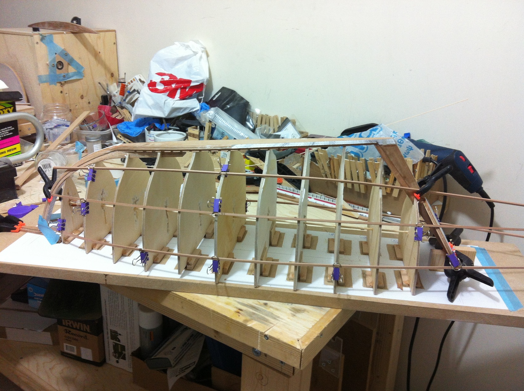
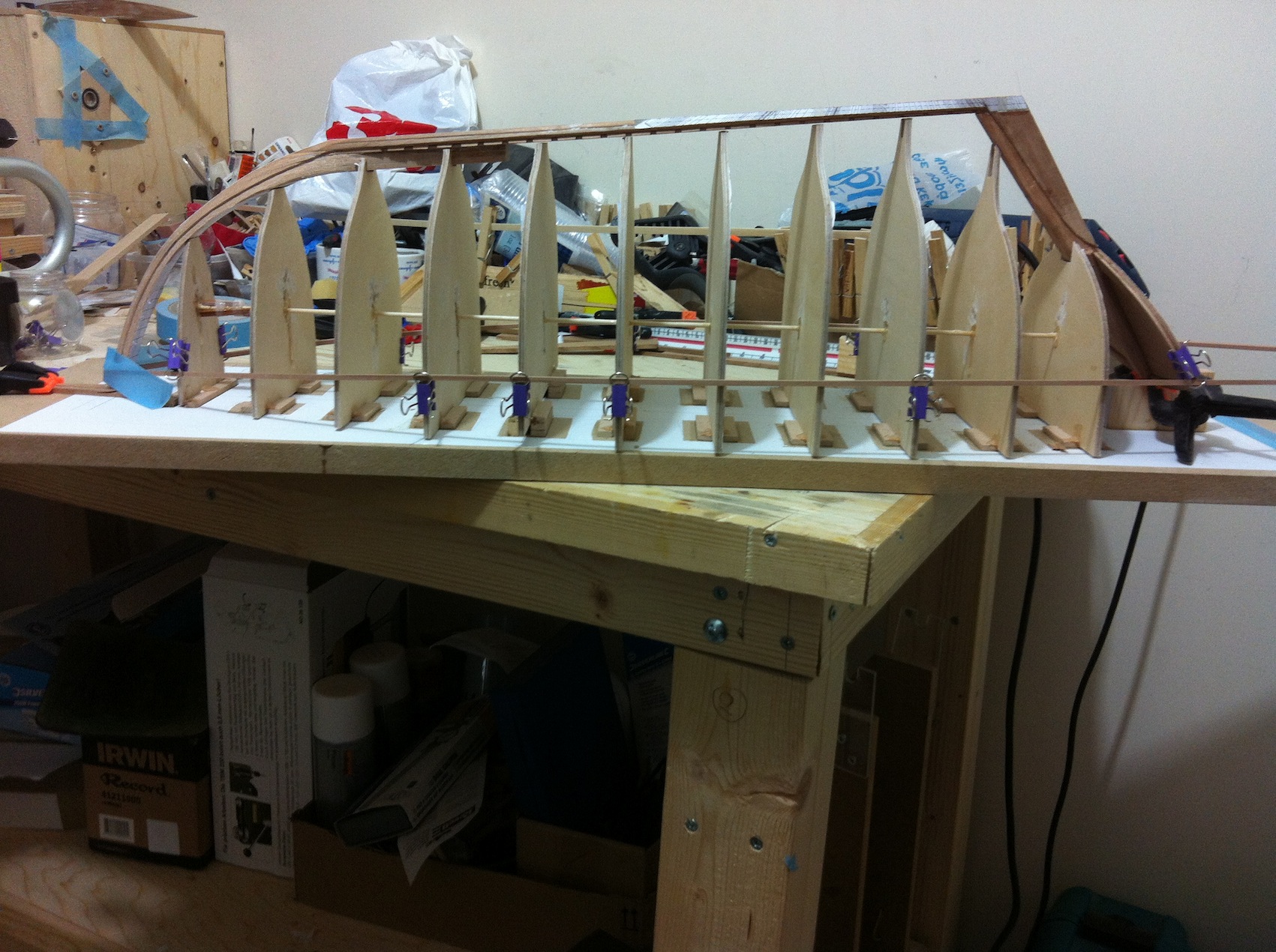
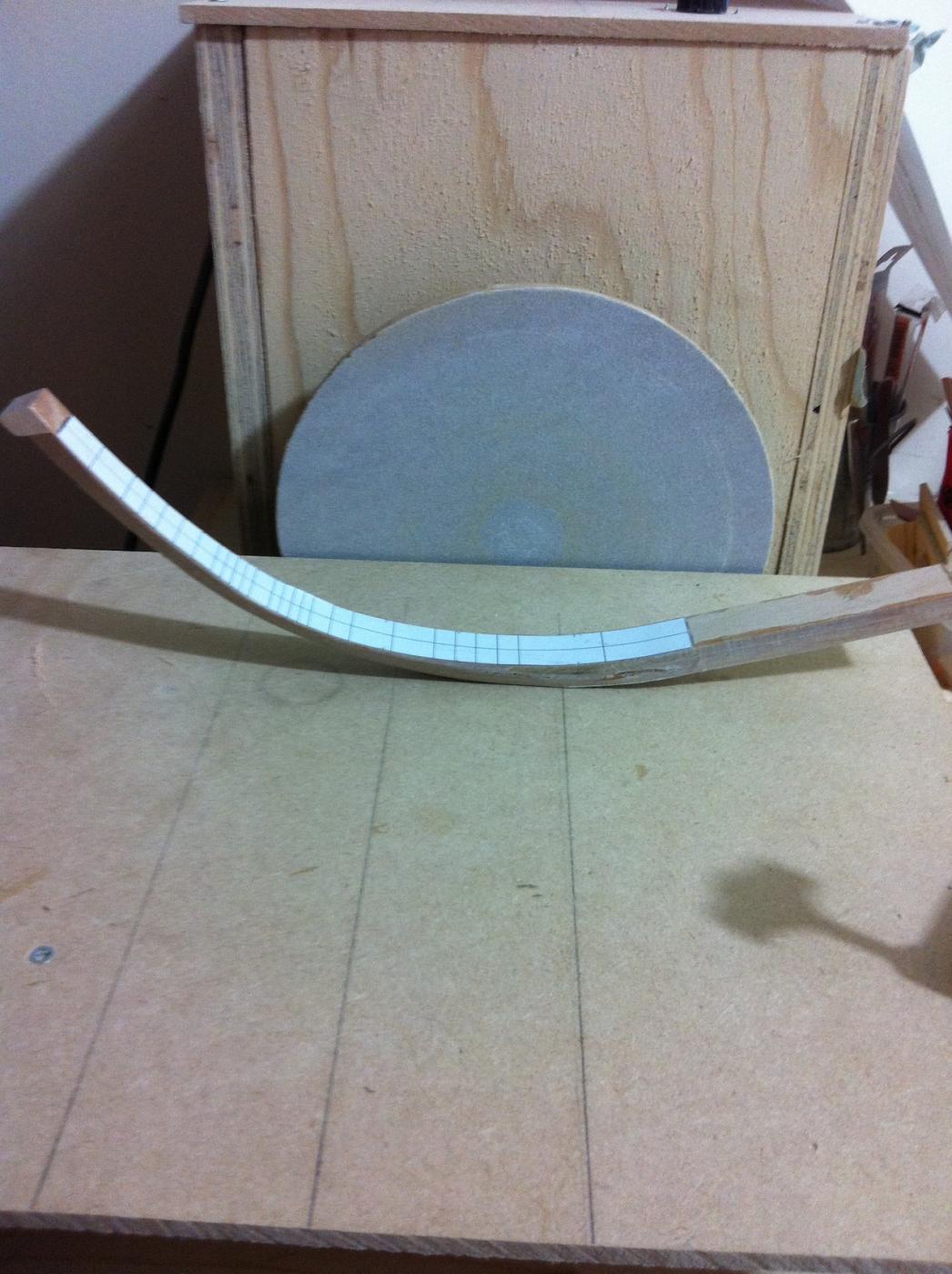
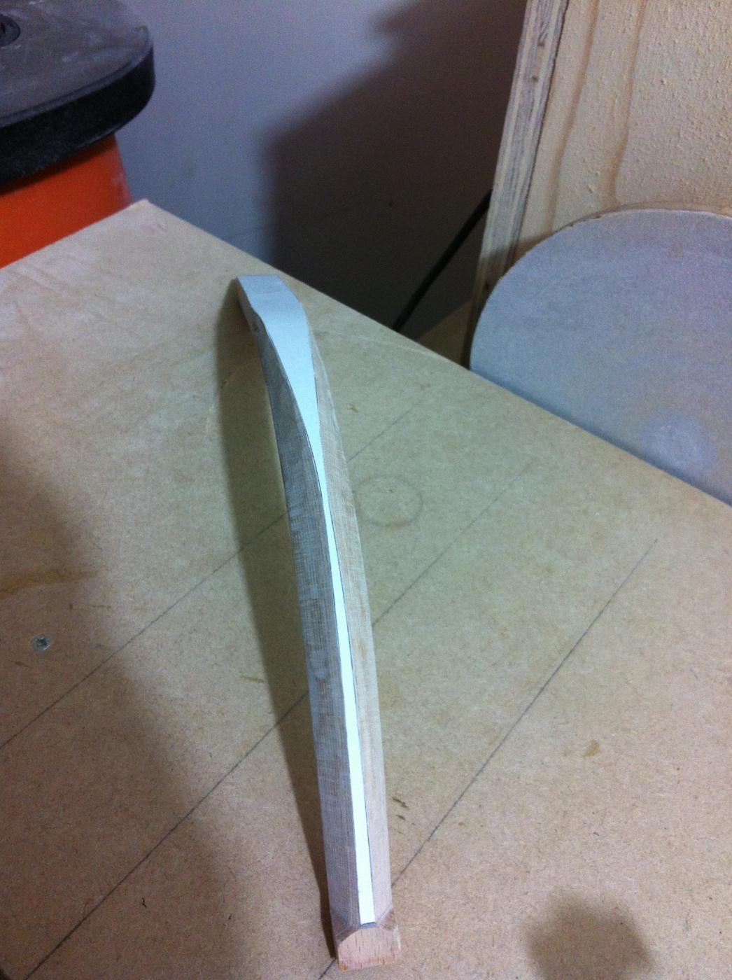
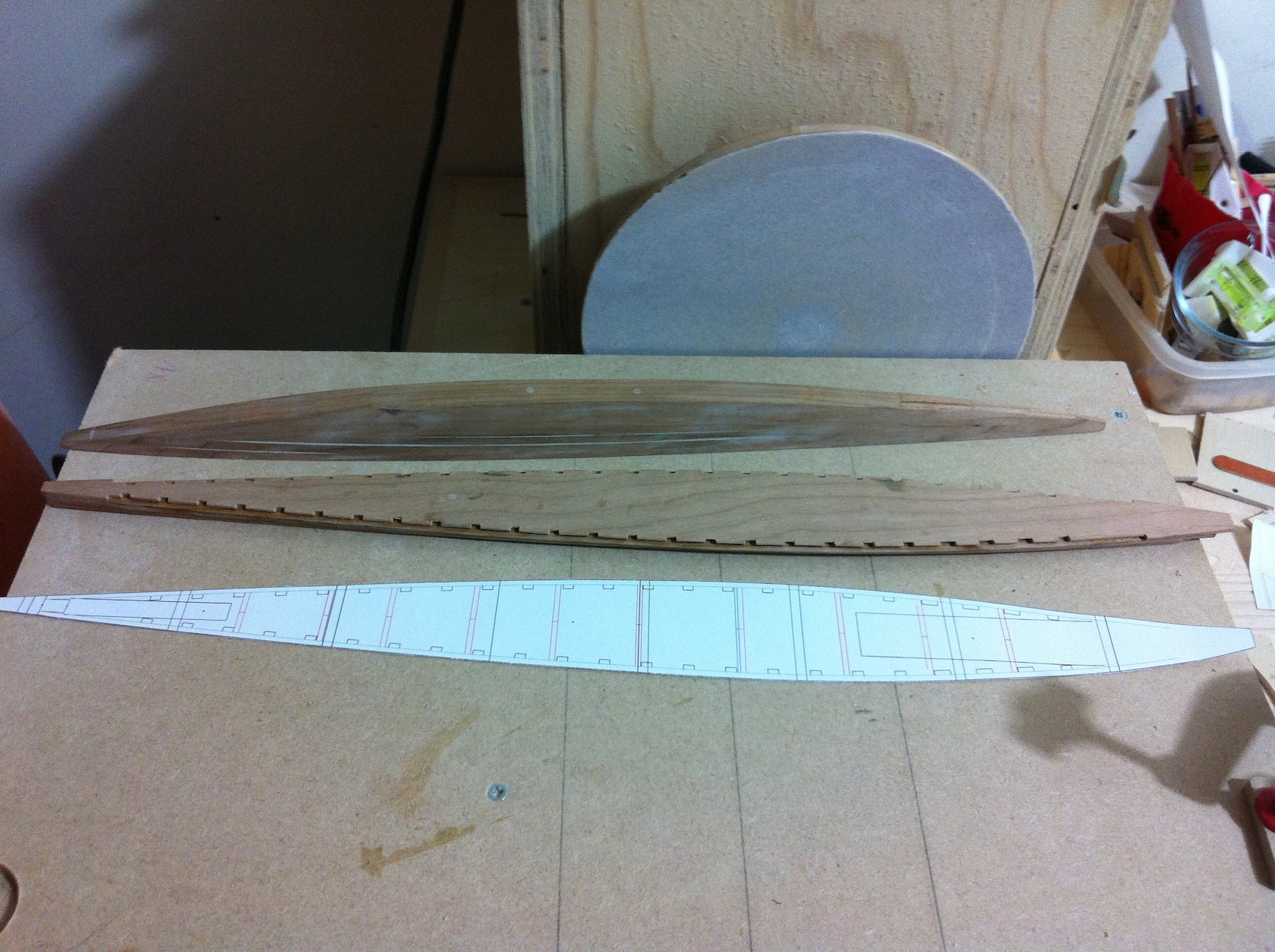
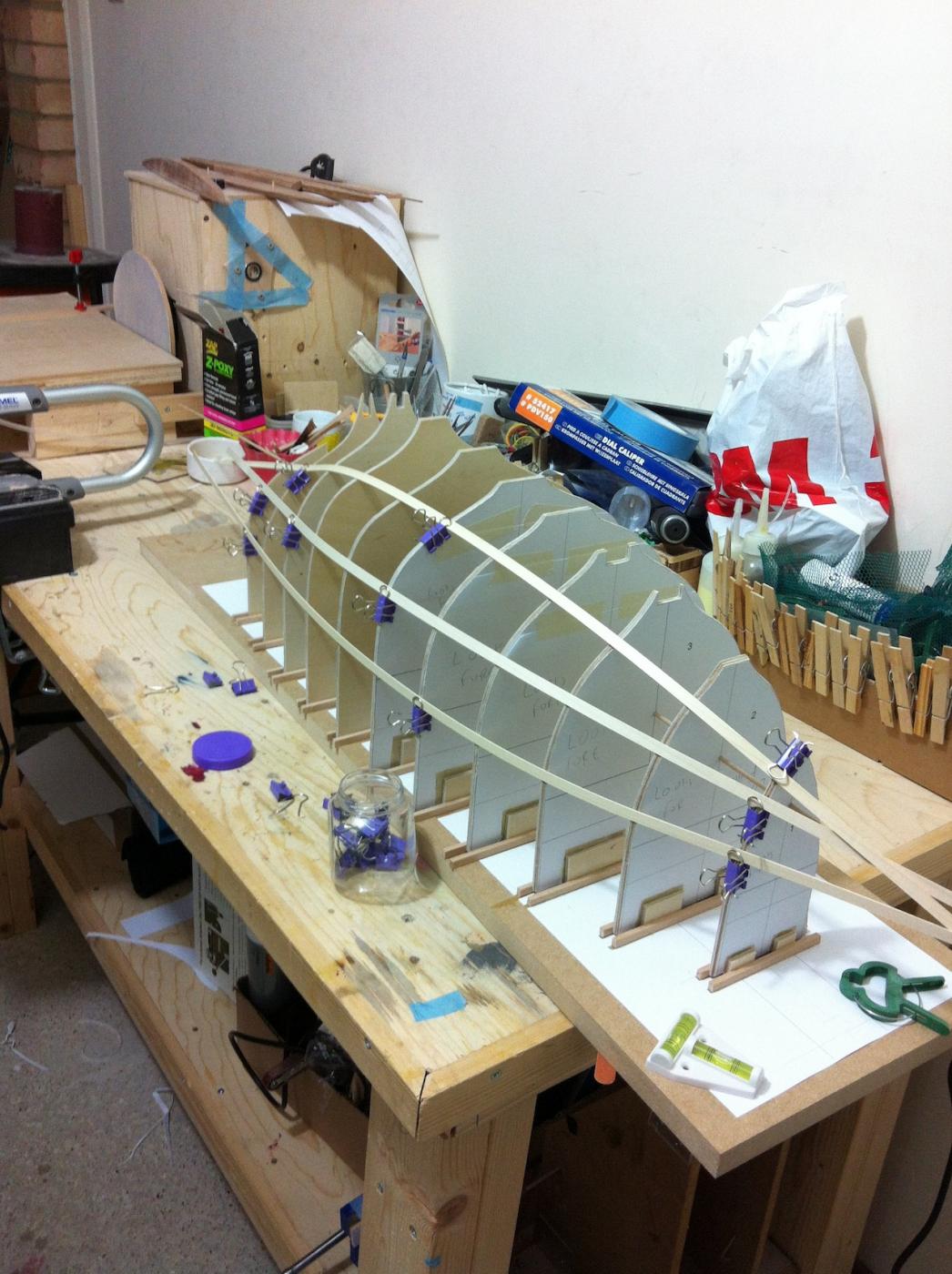
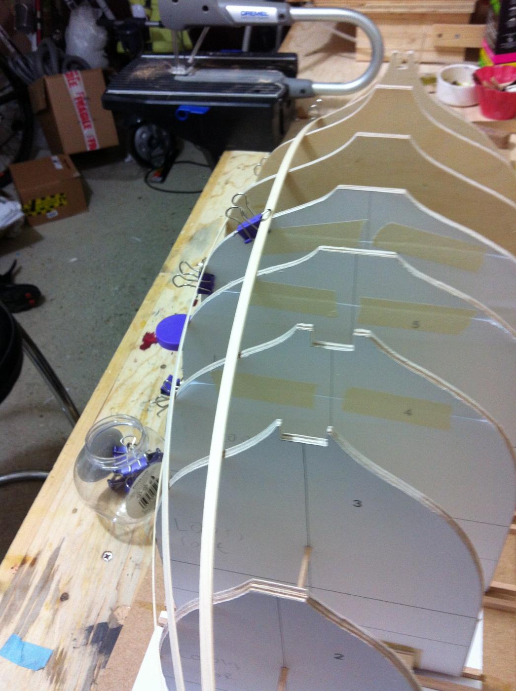
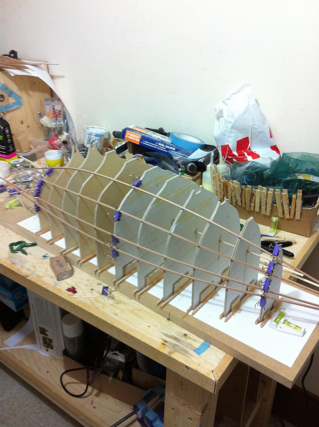
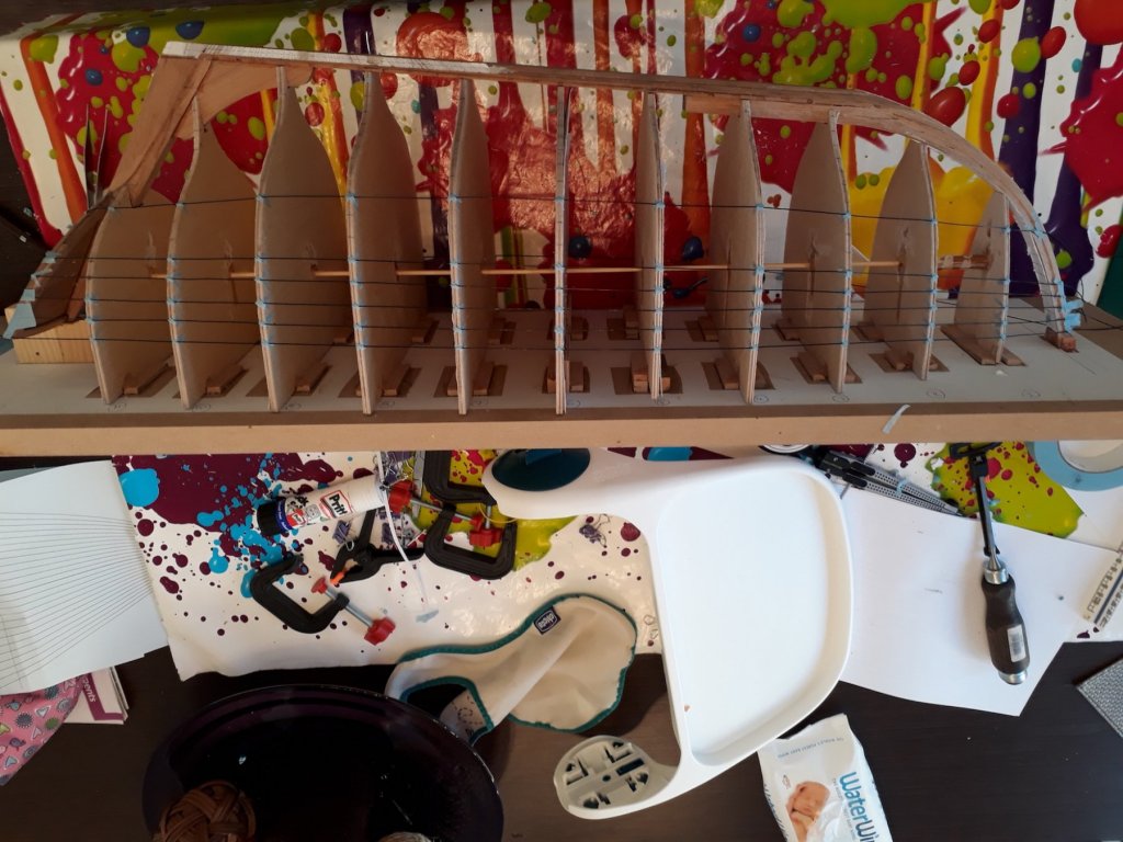
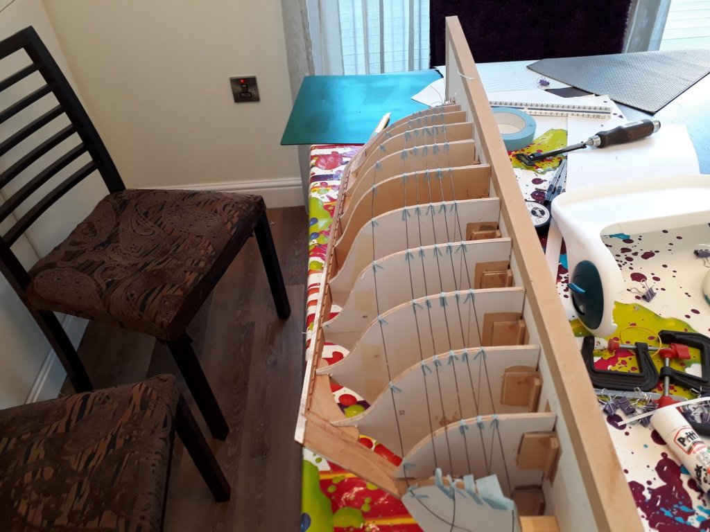
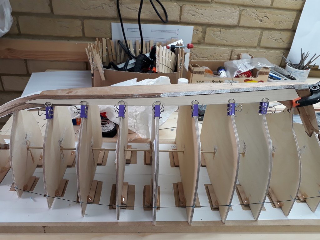
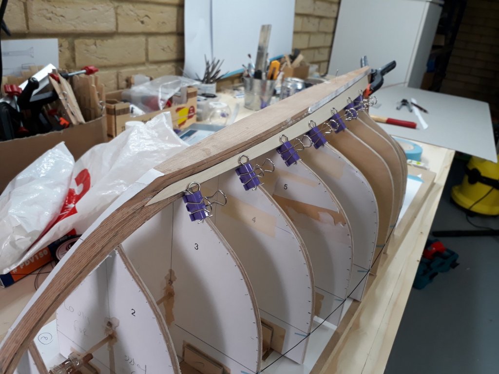
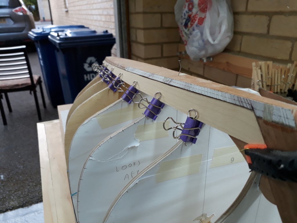
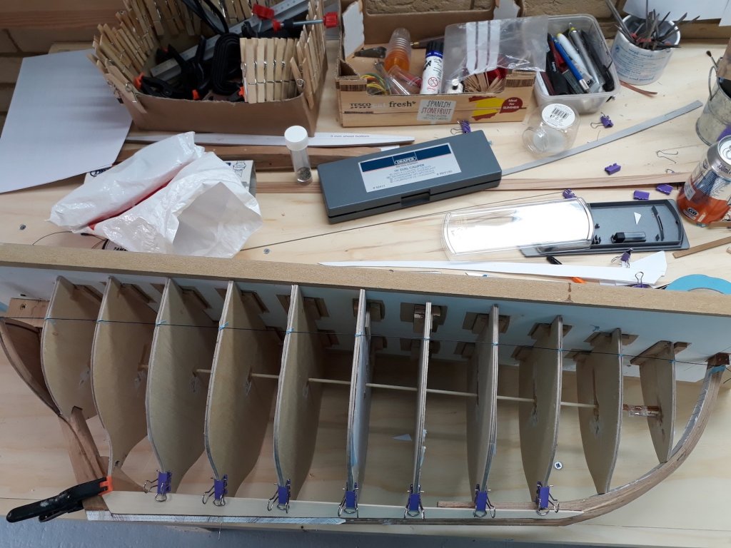
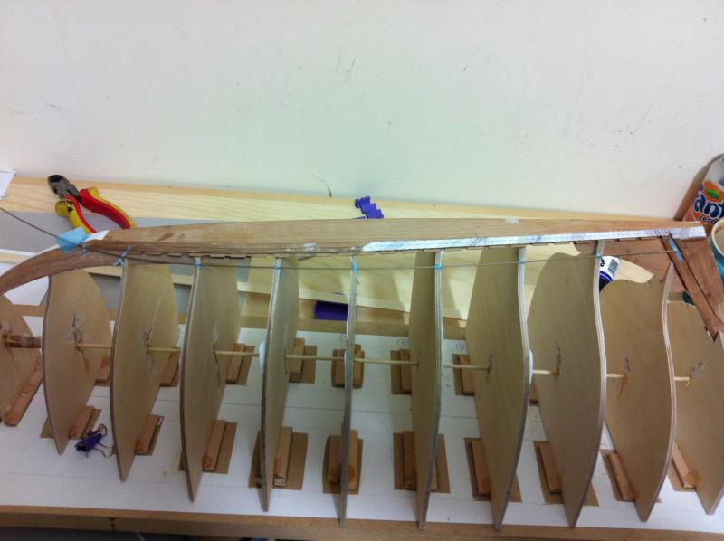
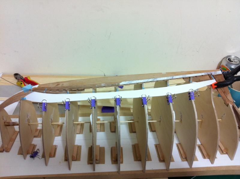
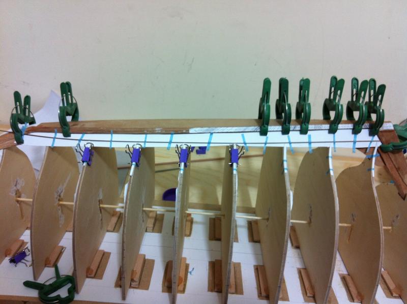
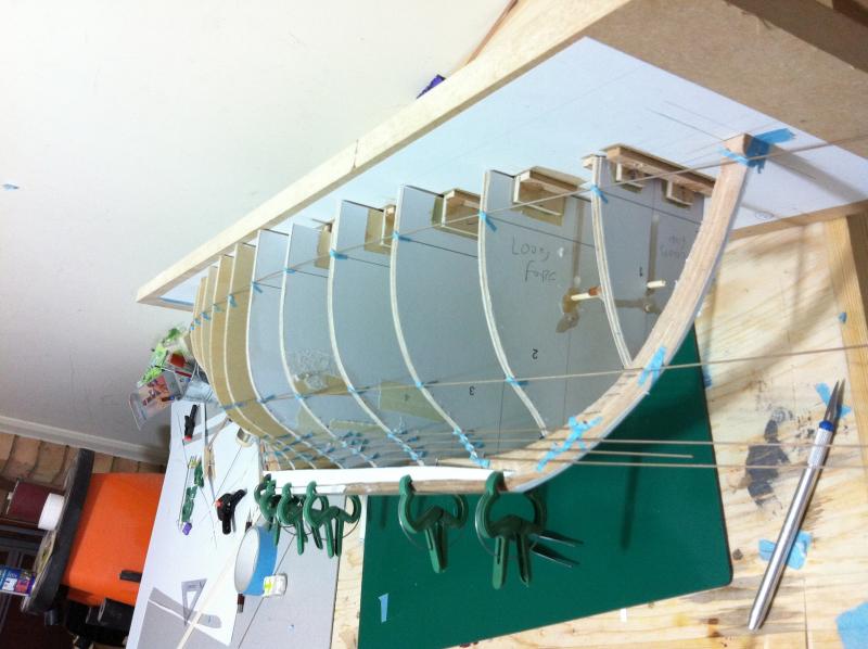
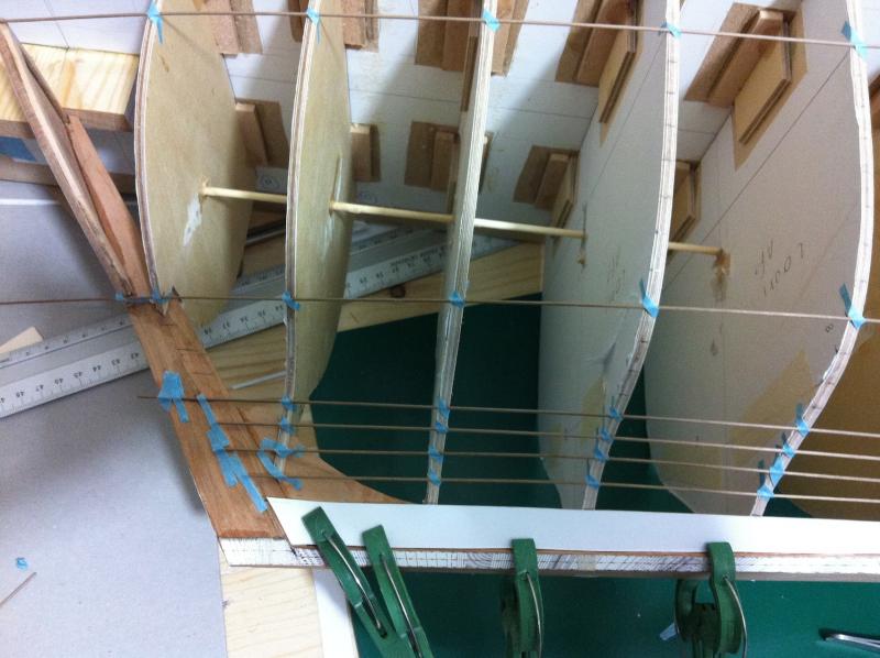
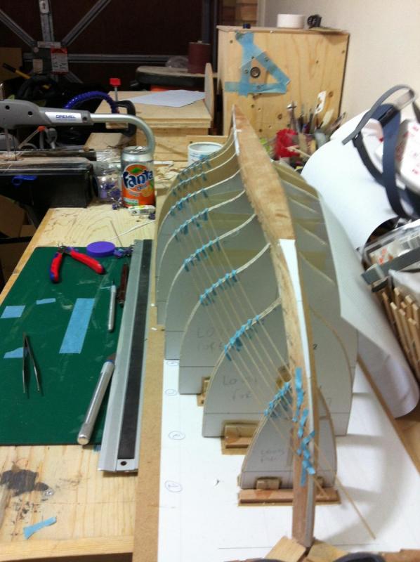
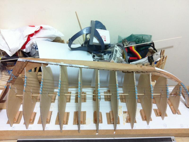
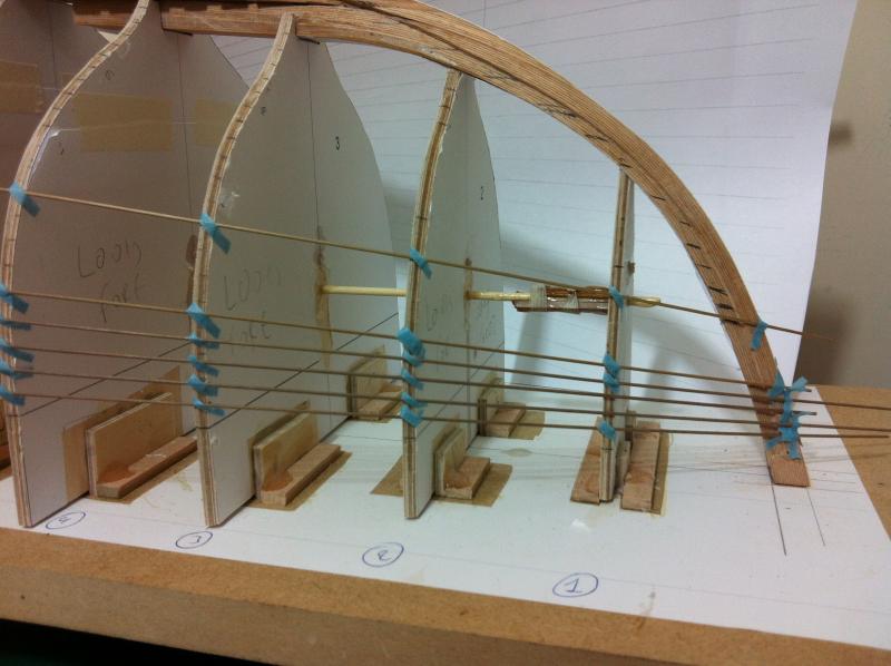
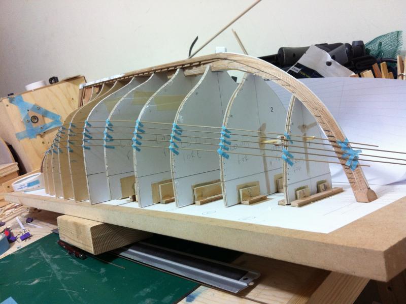
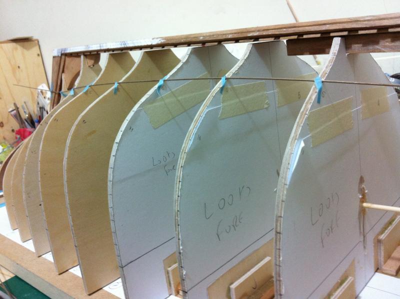
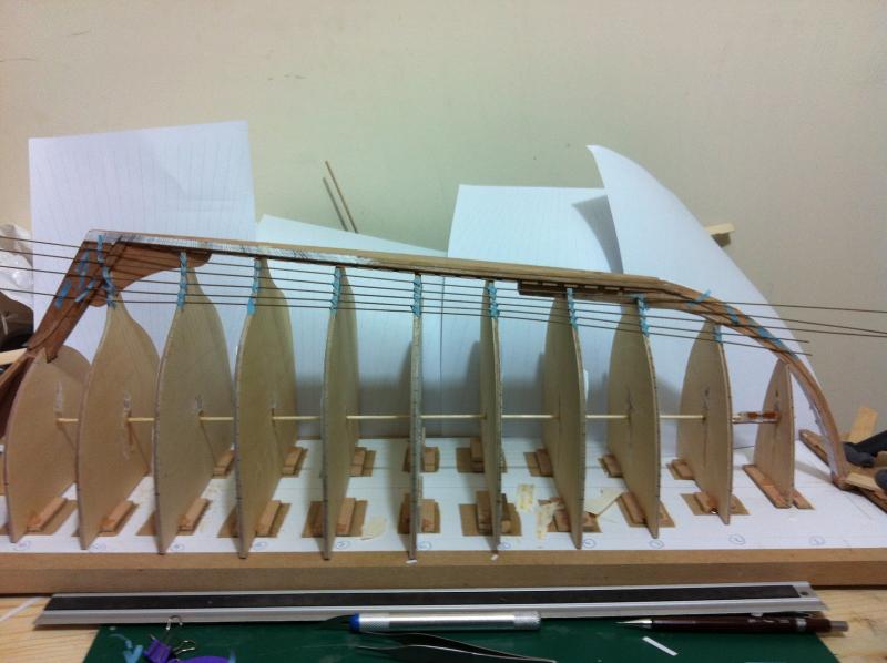
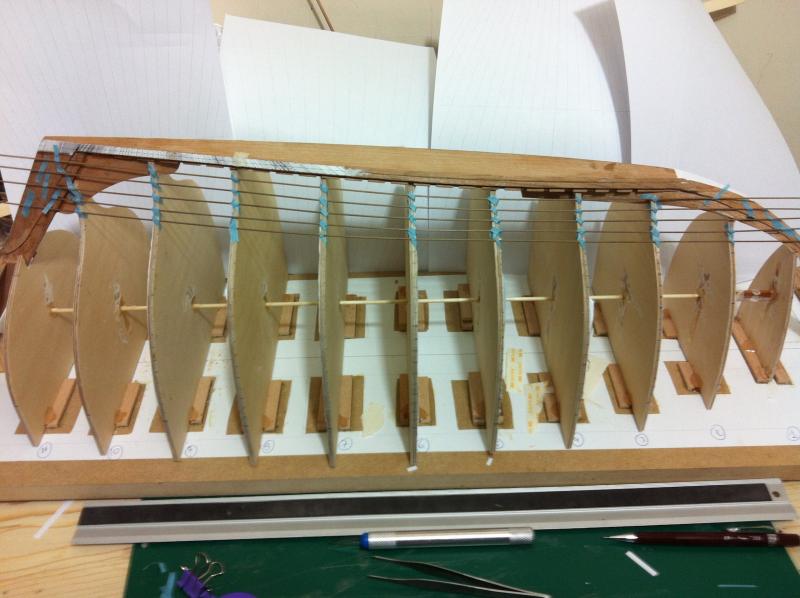
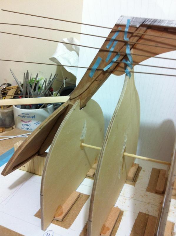
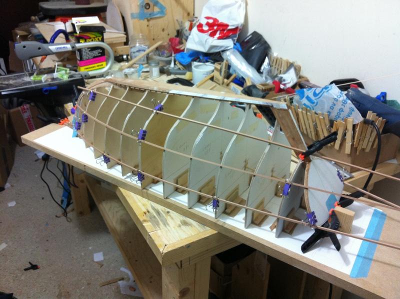
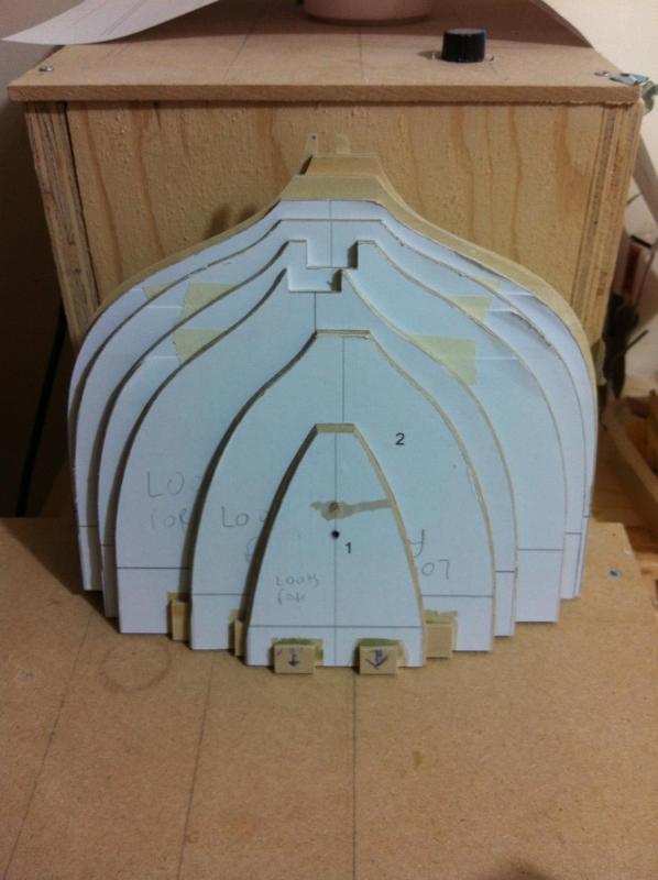
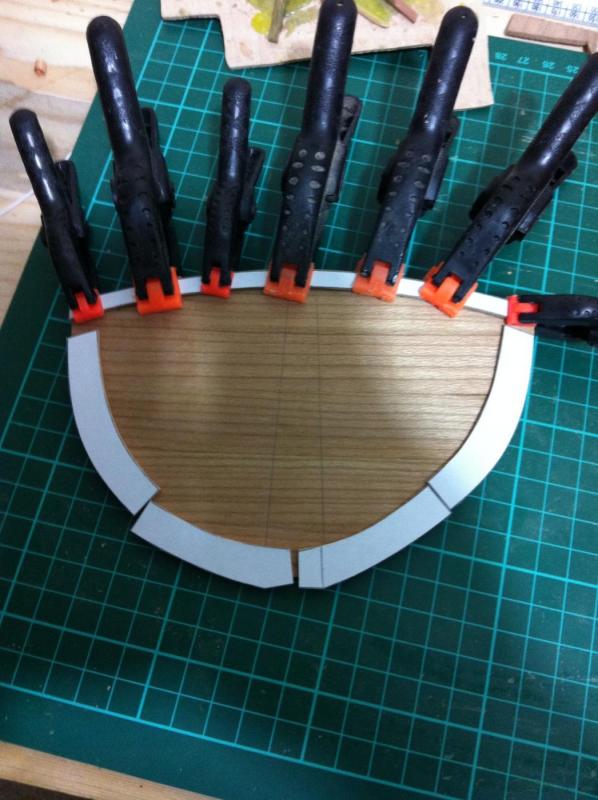
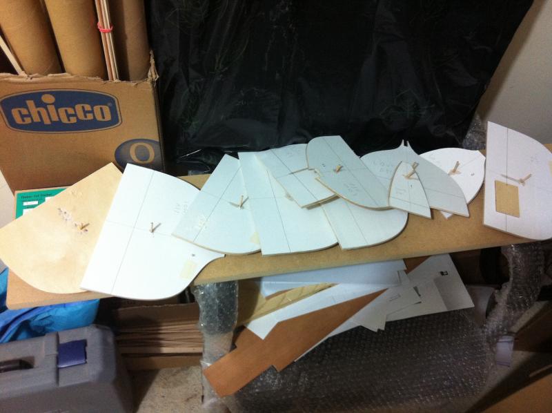
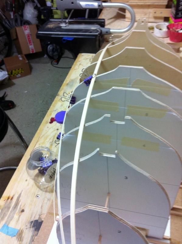
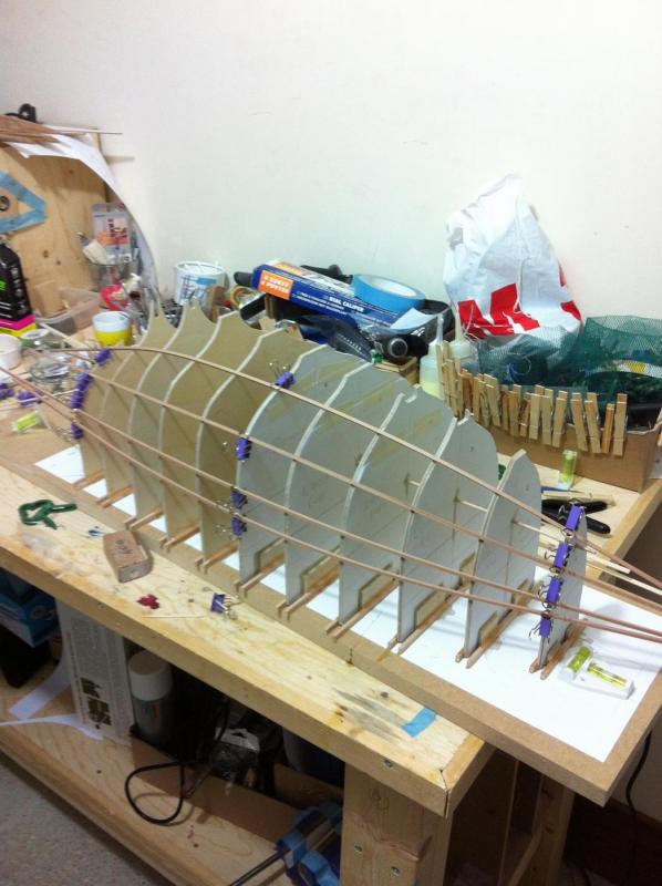
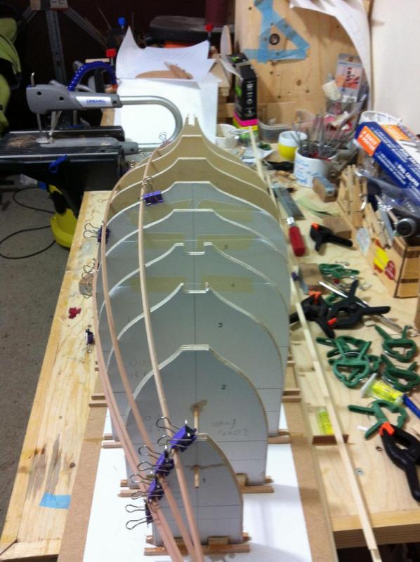
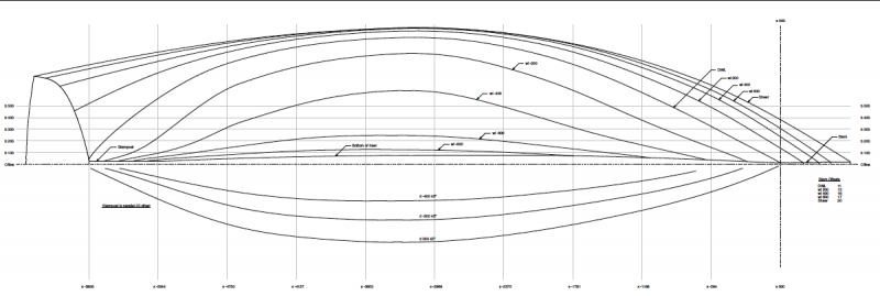
.thumb.jpg.6fd4c1b78768bb3efd745ab810936005.jpg) Thank you John and Patrick, indeed it felt nice to be working again, model building brings out the child in me! Dear Mark, your post was very encouraging, despite months of thinking, googling, going through the forum and reading tutorials, my planking still is 90% guessing and experimenting and 10 % evidence based. Having finished both GB planks, I compared them and there was a significant difference in width! I could not really understand how this happened, still I ended up redoing both planks again. They are now almost equal width and they seem to be fitting better. The GB planks need to bent, not to a huge degree but as the planks are maple 2 mm I think heat will be needed. I would like to steam bend these but it is difficult to set up a steaming device so probably it will be dry heat with a hair dryer Having finished the GB planks, I continued with the rest of the planking. This is how I am doing this: I decided to use 14 planks plus the garboard, so 15 planks altogether. I marked the edges of the GB planks on the frames, and used the template fan to divide 3 of the frames, one in the middle and in either ends of the hull. I then used a 1 mm dowel to divide the hull into 2 zones, eyeballing the curve so that it looked fair from all angles. I made sure it made contact with the sternpost and stem in a way that enough space is left for the rest of the planks in either direction, without getting cramped. I then replaced the dowel with black fishing line and continued dividing the zones in halves, eyeballing the curve to be reasonably fair. I finished the upper four strakes but this is a difficult job, I have a feeling that this eyeballing thing is a skill the develops over time into a sixth sense. Quite a few times the curve looked wrong but when I re-did it the batten went on the same place. Other times just a couple of mm had a huge impact on how the curve felt. Apologies for the quality of the photos, it is not easy to fit the boat in the picture!
Thank you John and Patrick, indeed it felt nice to be working again, model building brings out the child in me! Dear Mark, your post was very encouraging, despite months of thinking, googling, going through the forum and reading tutorials, my planking still is 90% guessing and experimenting and 10 % evidence based. Having finished both GB planks, I compared them and there was a significant difference in width! I could not really understand how this happened, still I ended up redoing both planks again. They are now almost equal width and they seem to be fitting better. The GB planks need to bent, not to a huge degree but as the planks are maple 2 mm I think heat will be needed. I would like to steam bend these but it is difficult to set up a steaming device so probably it will be dry heat with a hair dryer Having finished the GB planks, I continued with the rest of the planking. This is how I am doing this: I decided to use 14 planks plus the garboard, so 15 planks altogether. I marked the edges of the GB planks on the frames, and used the template fan to divide 3 of the frames, one in the middle and in either ends of the hull. I then used a 1 mm dowel to divide the hull into 2 zones, eyeballing the curve so that it looked fair from all angles. I made sure it made contact with the sternpost and stem in a way that enough space is left for the rest of the planks in either direction, without getting cramped. I then replaced the dowel with black fishing line and continued dividing the zones in halves, eyeballing the curve to be reasonably fair. I finished the upper four strakes but this is a difficult job, I have a feeling that this eyeballing thing is a skill the develops over time into a sixth sense. Quite a few times the curve looked wrong but when I re-did it the batten went on the same place. Other times just a couple of mm had a huge impact on how the curve felt. Apologies for the quality of the photos, it is not easy to fit the boat in the picture!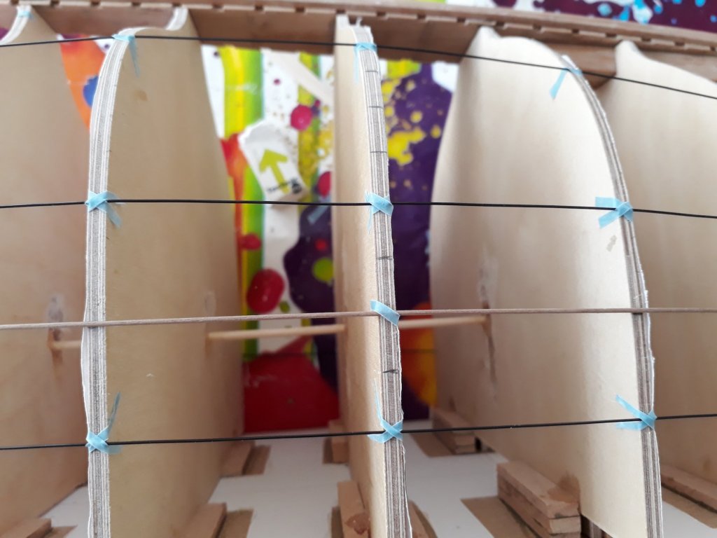


-
Tools You Can't Live Without
vaddoc replied to Justin P.'s topic in Modeling tools and Workshop Equipment
My home-made disc sander is by far the most useful tool I have. My dremel motosaw comes second and a 50 cm aluminium ruler third. With two babies at home I cannot really have alcohol, I am sure this is the reason behind my very slow progress! -
In my boat, a straight strip near the keel is way off the shape of the hull, whereas near the sheer is almost right following the curve of the hull. Now probably the sheer is the most important line as it defines the shape of the boat. Also, it is non flexible in shape. So the sheer plank needs to have a certain shape no matter what the planking plan will be and at least the next few planks also will not be very flexible in shape either, as they follow the sheer and probably will be very straight with little spilling needed. Now, if the planks near the sheer are left last, maybe they will need to be squeezed into shapes that will be unpleasing to the eye so maybe this is why they need to be done first. The shape of the planks mid hull have much less of a visual impact. I have very little experience in planking though so may be completely wrong
-
Bending with steam easily
vaddoc replied to a topic in Building, Framing, Planking and plating a ships hull and deck
I think water can only reach 100 C in its liquid state, then it turns to steam which is its gas state and can reach much higher temperatures. Another trick is to wrap your strips in a wet towel and put it in the microwave! -
I am a novice in planking but I have had the exact same problem, although I think I ve cracked it. The way I understand this is that placement of the garboard is a compromise of many things. 1. If you place a straight strip right where the garboard should be, it will end up in the lower third of the stem 2. There is much less space for the planks at the bow compared to the stern or mid hull so the garboard needs to end as low as possible at the stem to allow space for the rest of the planks. 3. It is not possible for the gb to end mid keel, it needs to finish somewhere at the stem really 4. Spilling needs to be reasonable, planks should not have unreasonable curves 5. When the gb is outlined on the frames, the curves should be fair and pleasing to the eye. 6. The rest of planking will be outlined after the gb is defined 7. If you are planking upside down, turn the hull right way up and have a look, makes a huge difference Ultimately, the gb is set by eyeballing things. Still, I might be completely wrong!
-
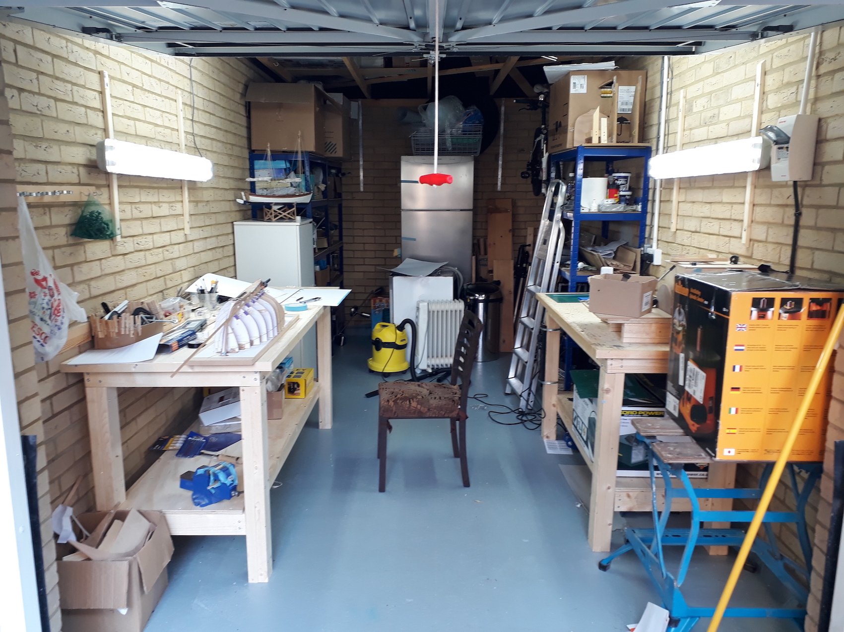
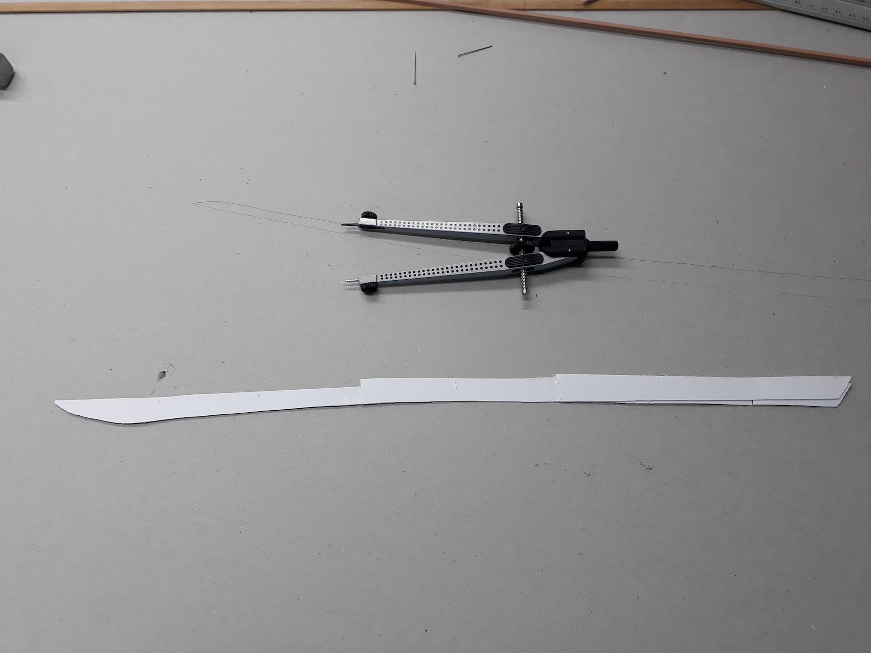
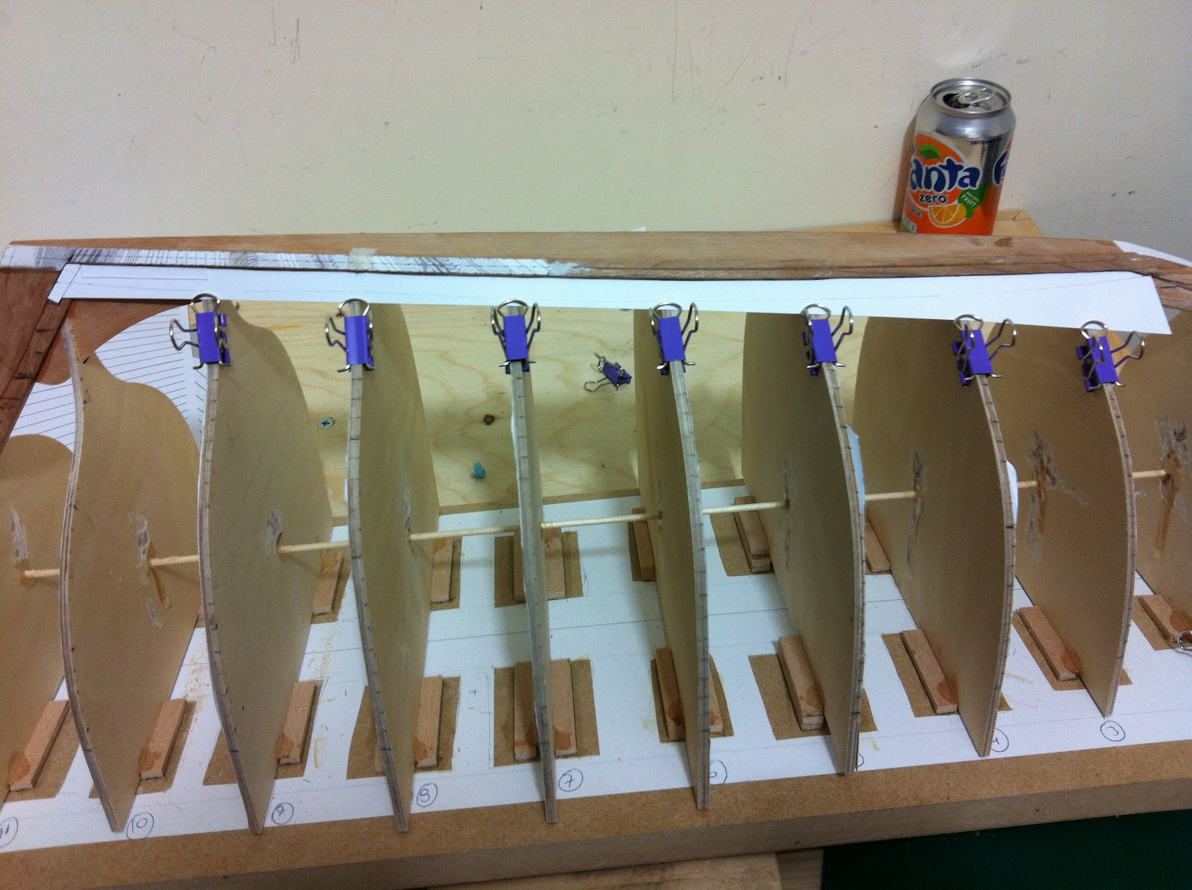
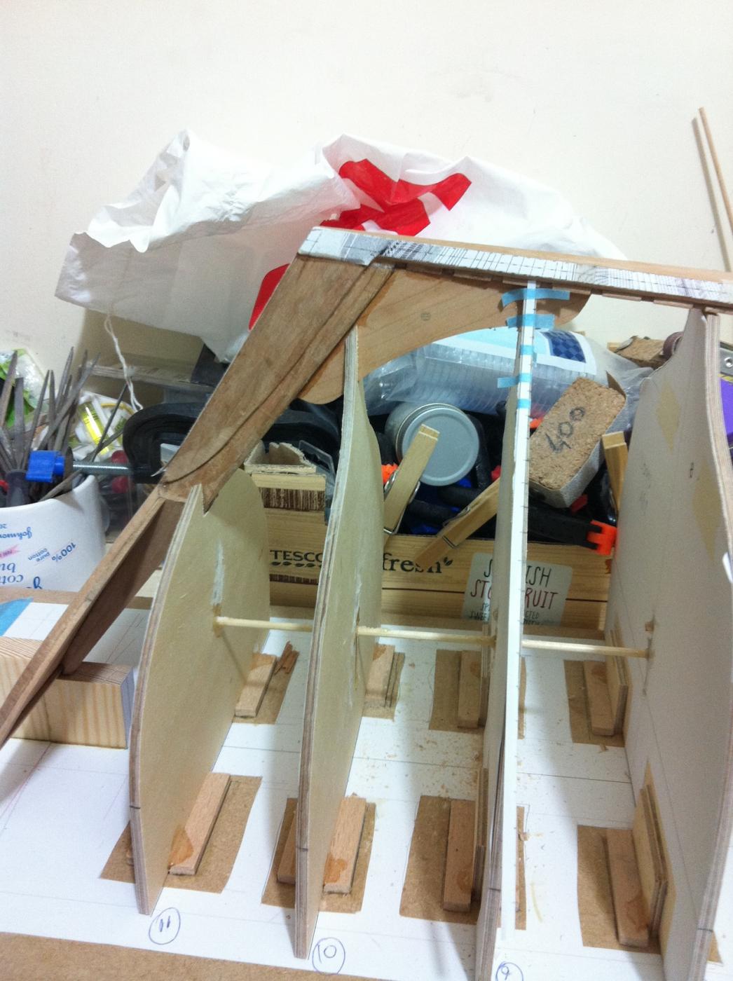
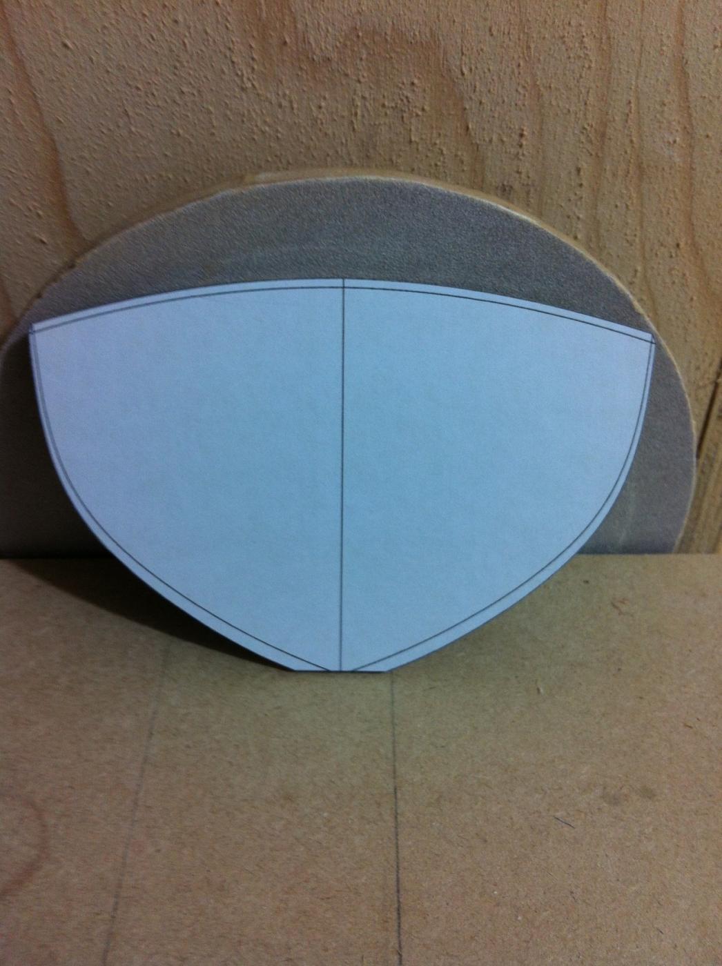
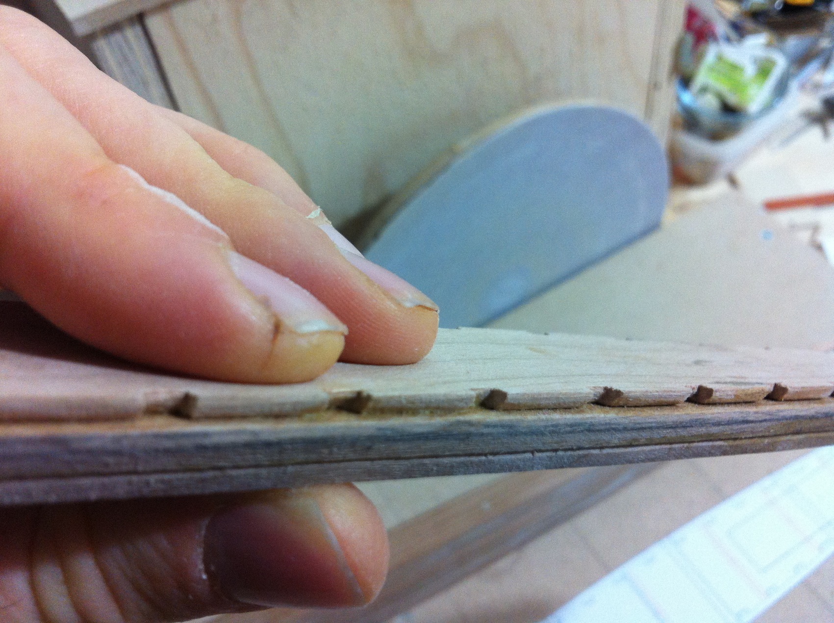
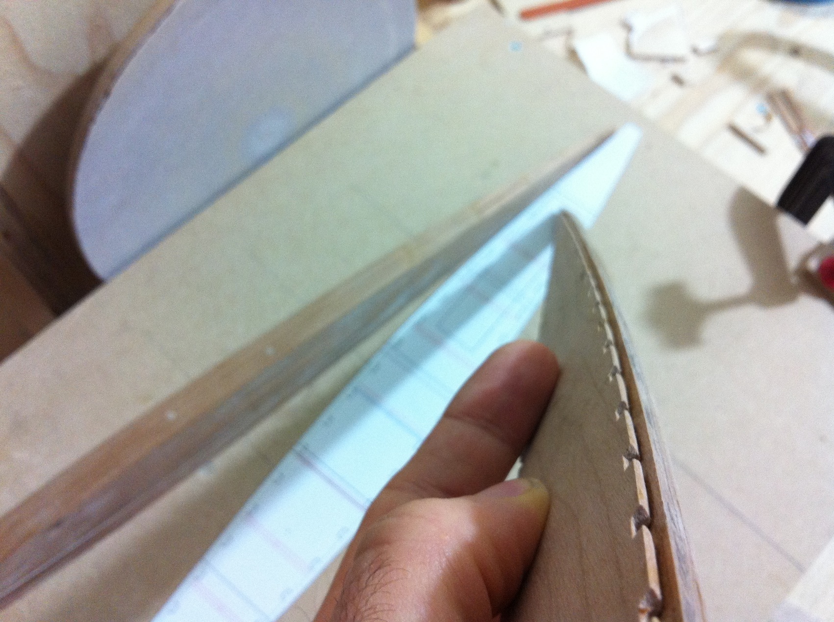
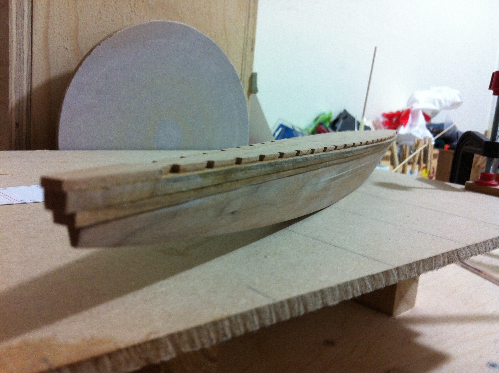
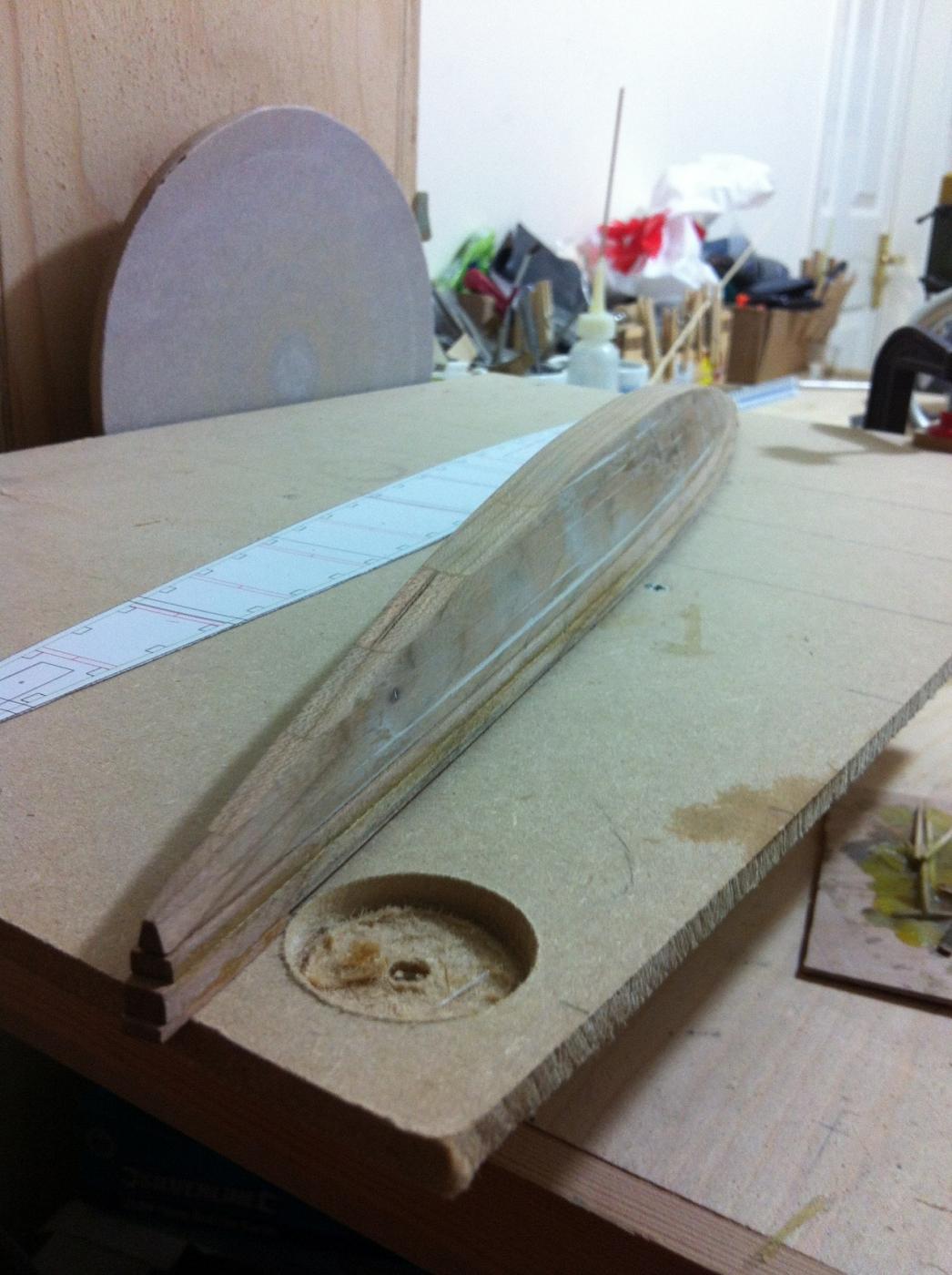
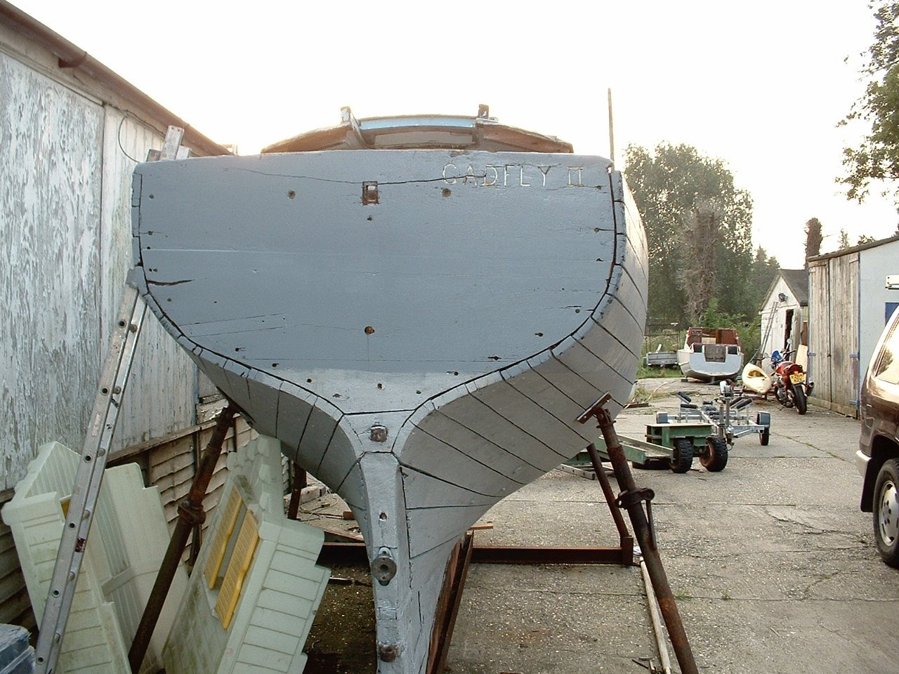
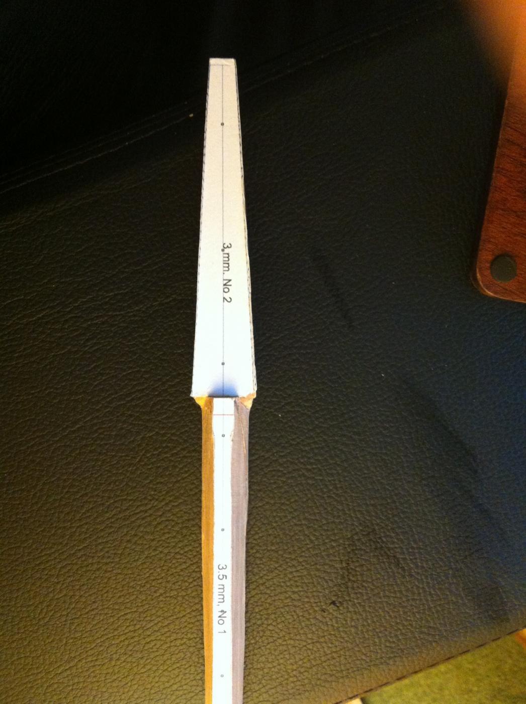
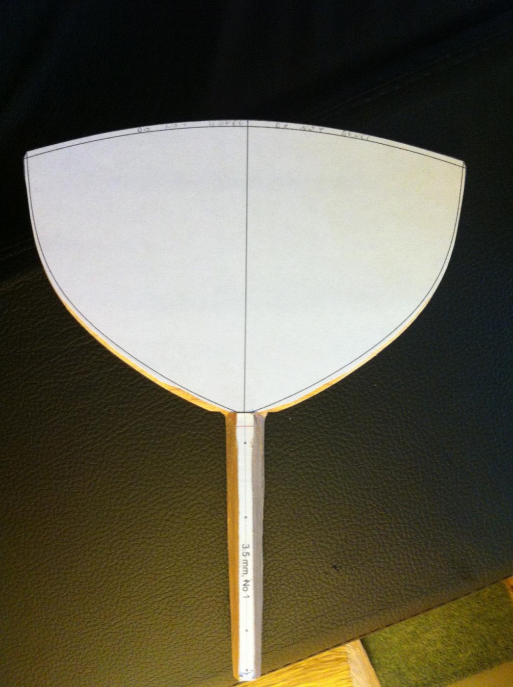
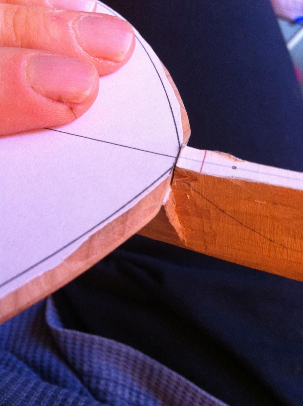
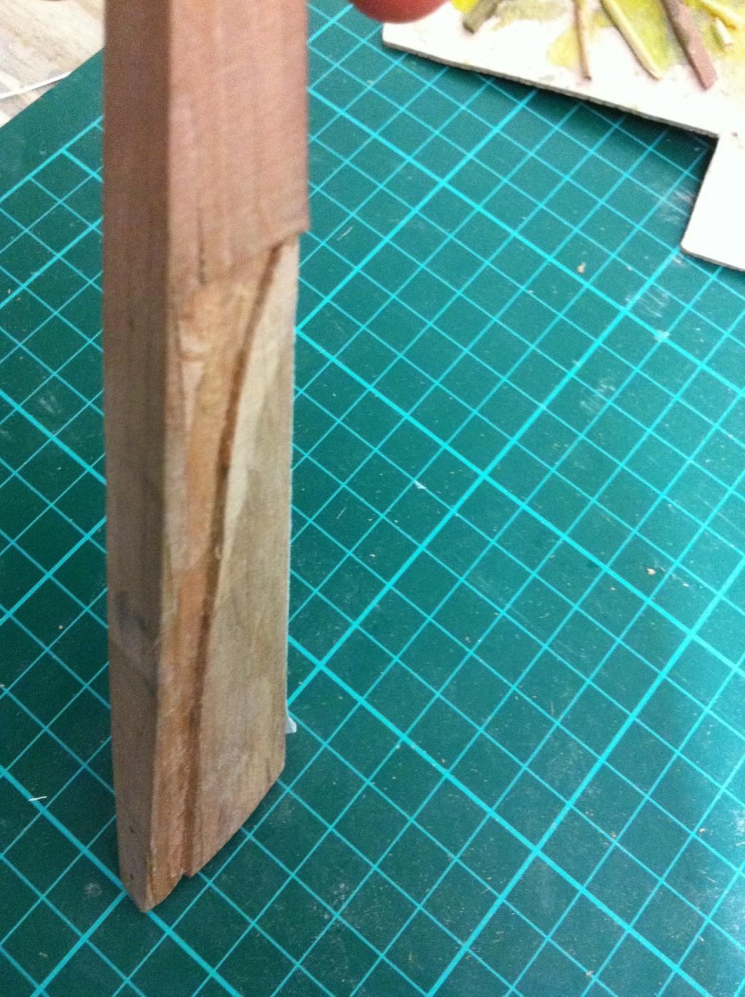
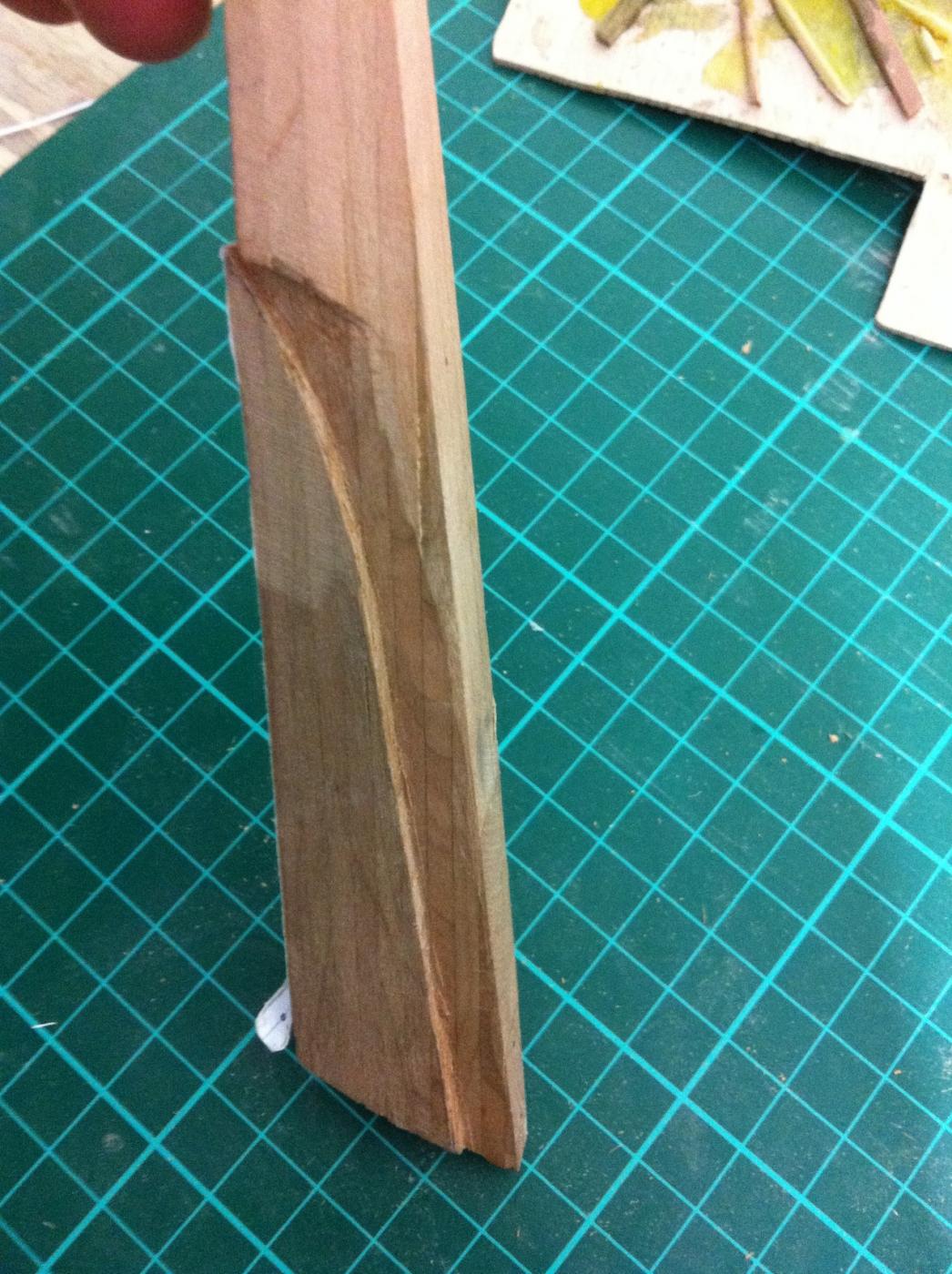
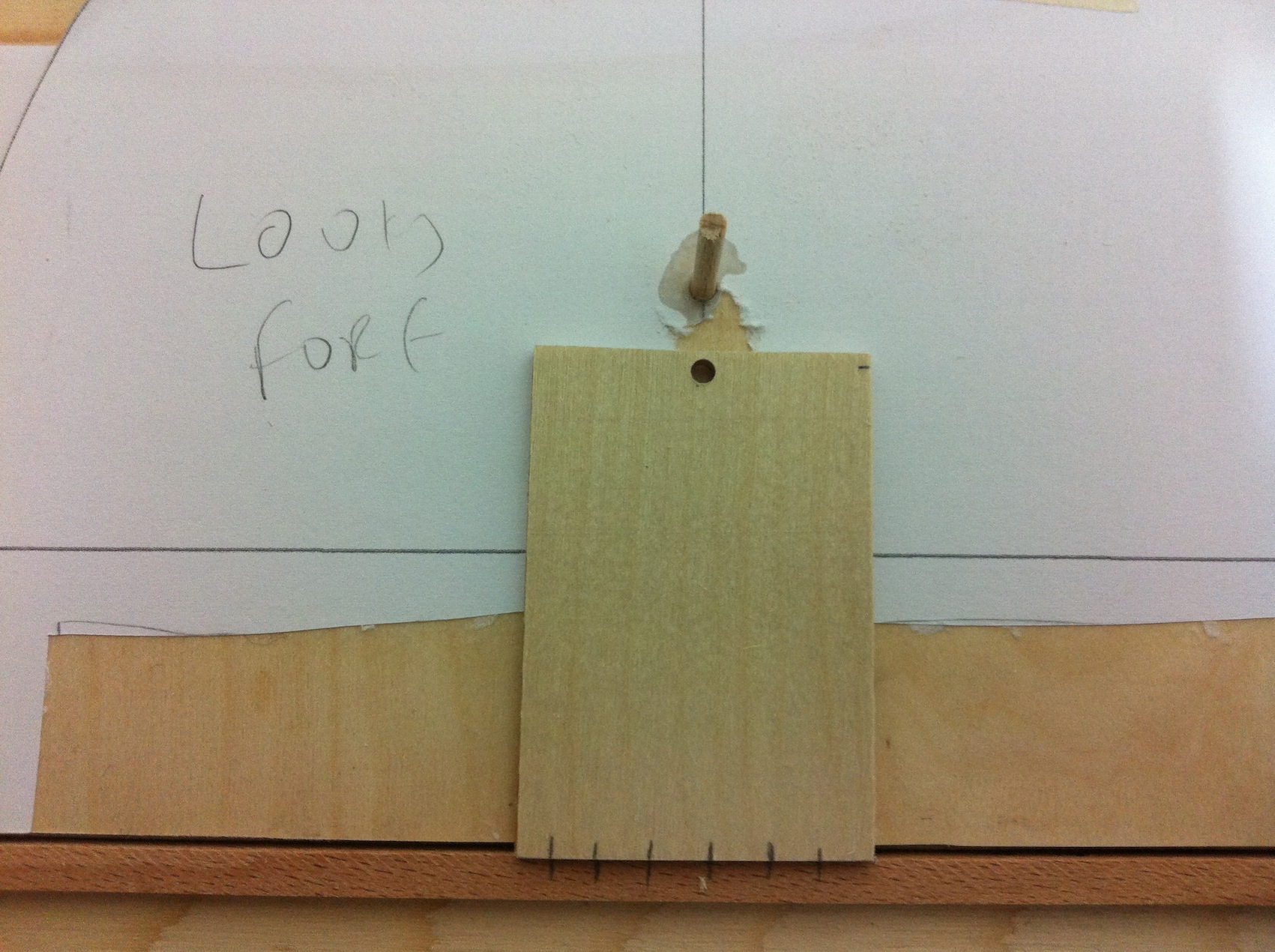
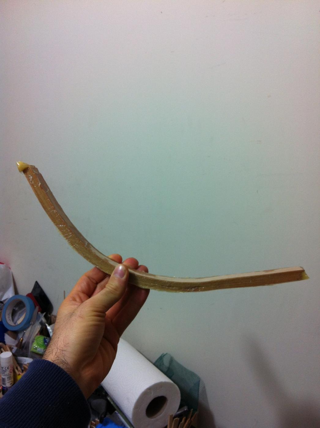
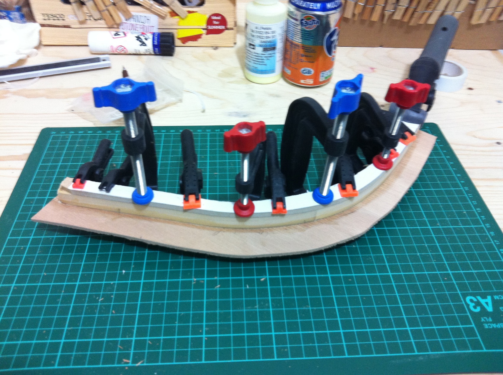
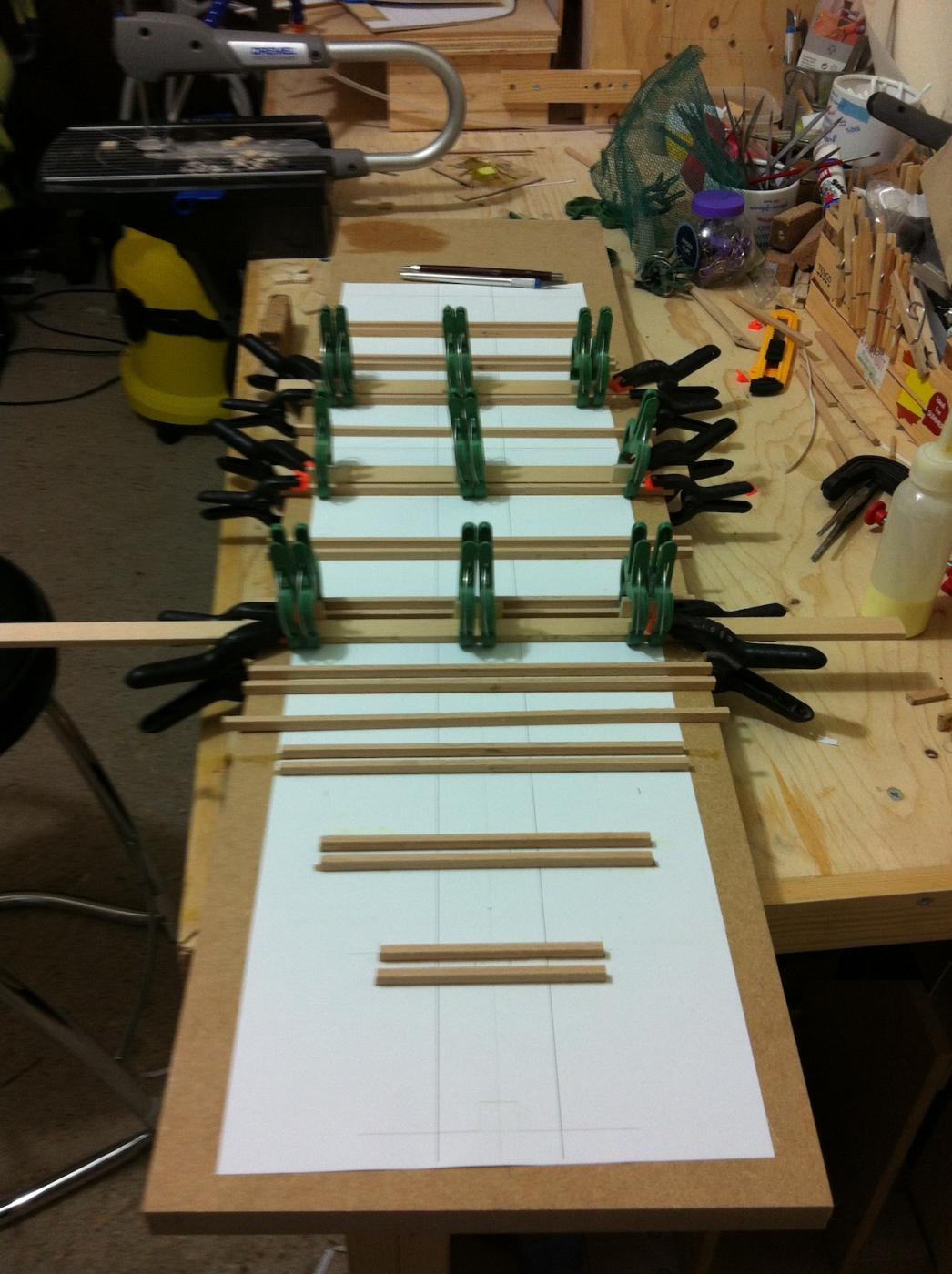
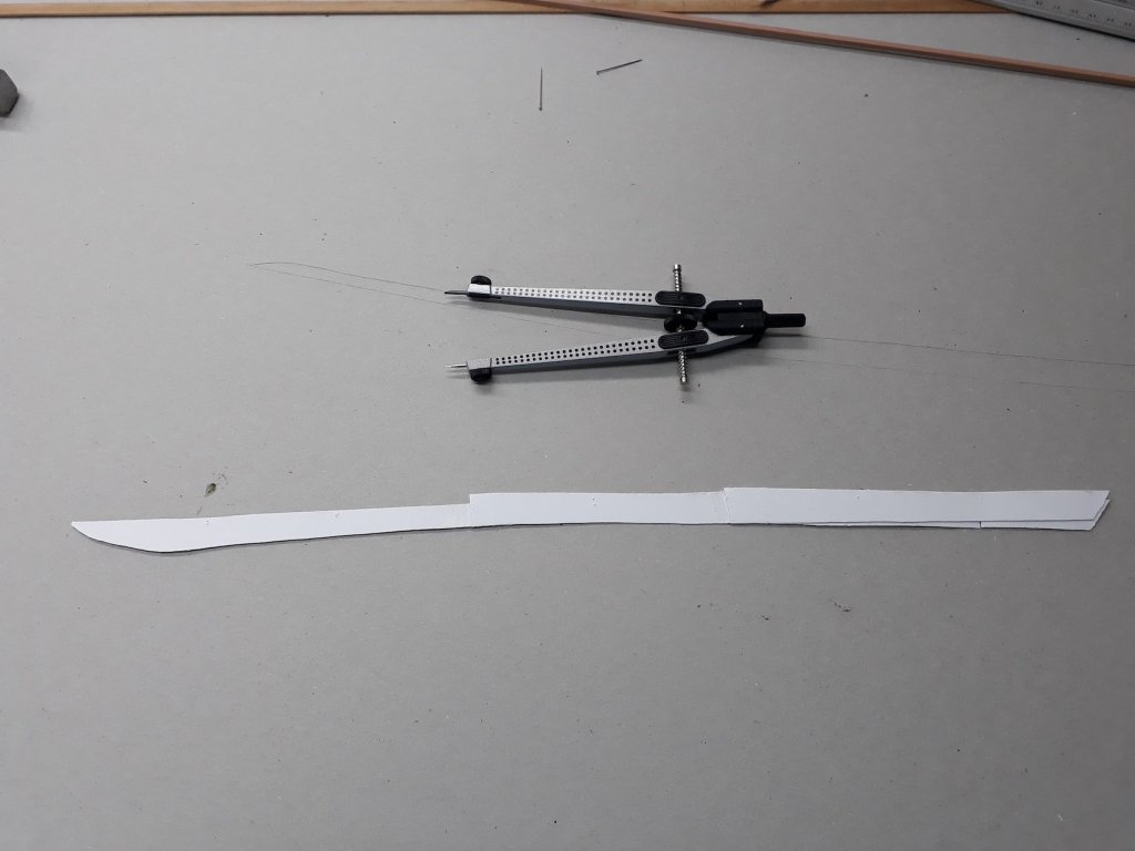
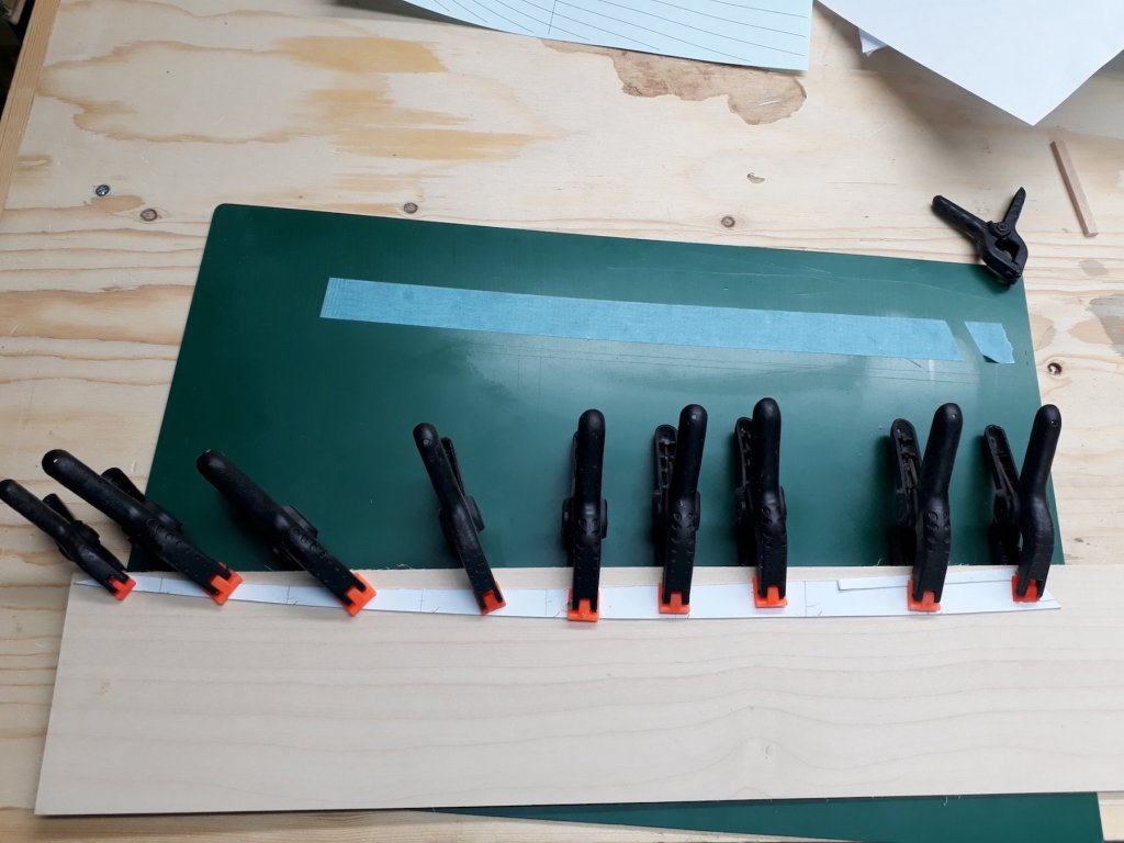
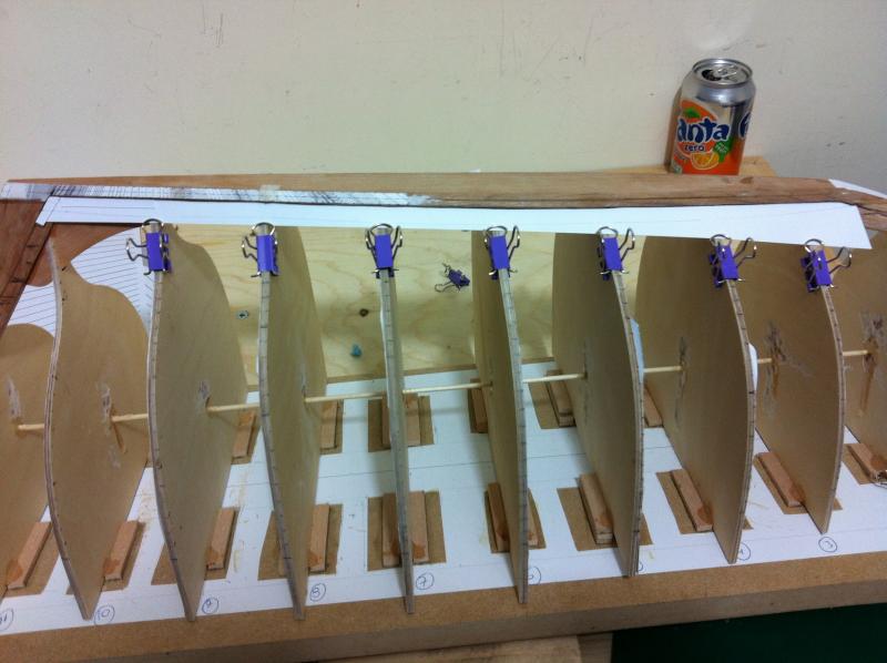
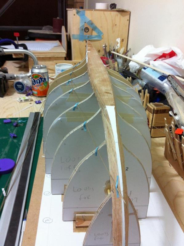
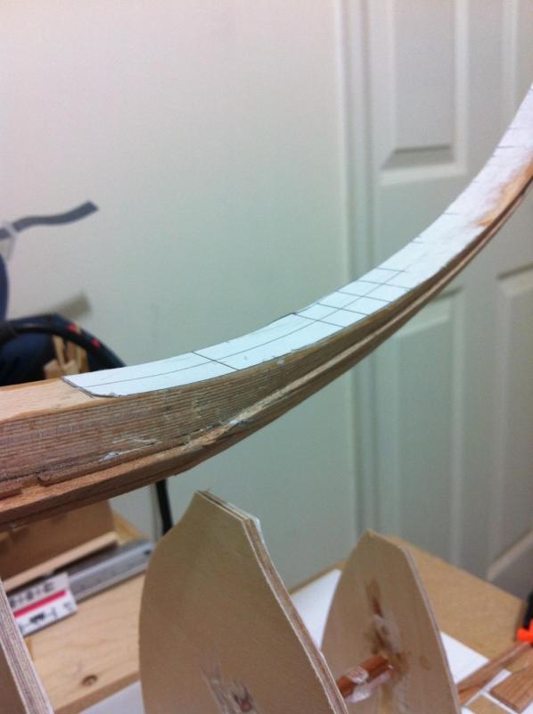
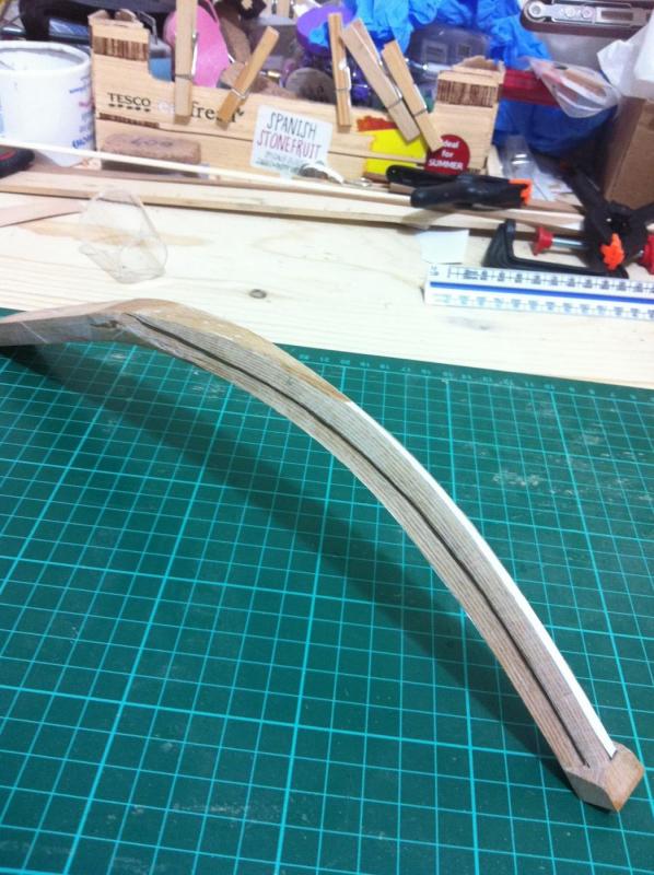
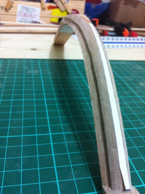
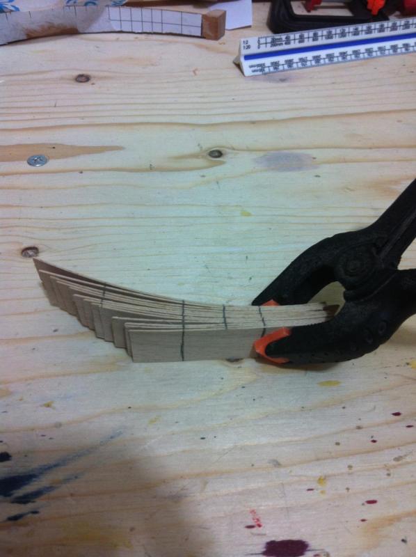
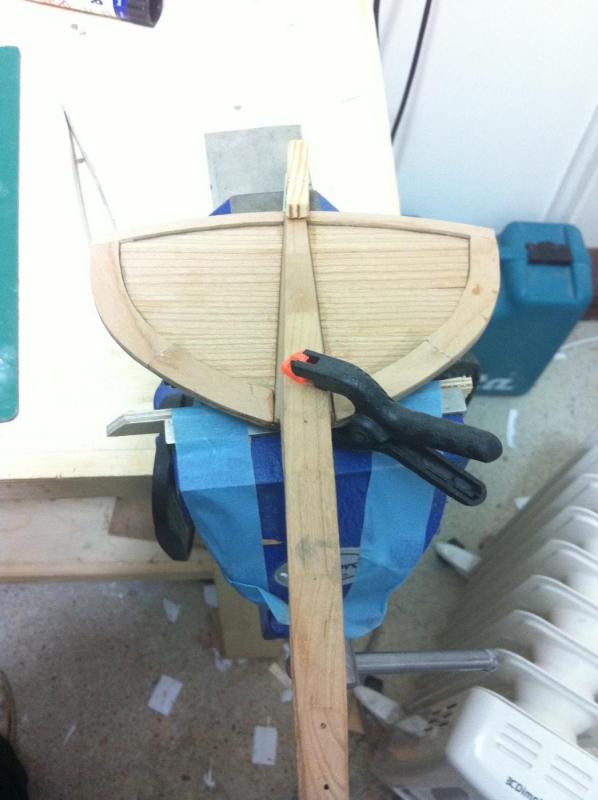
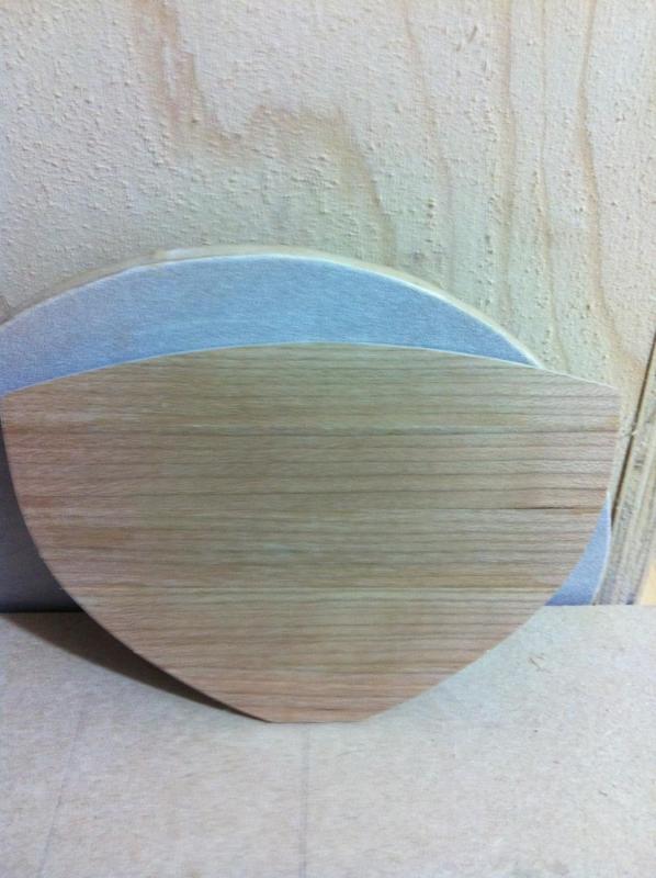
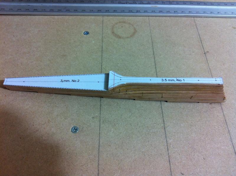
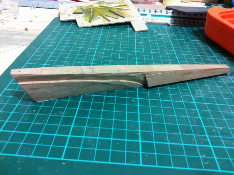
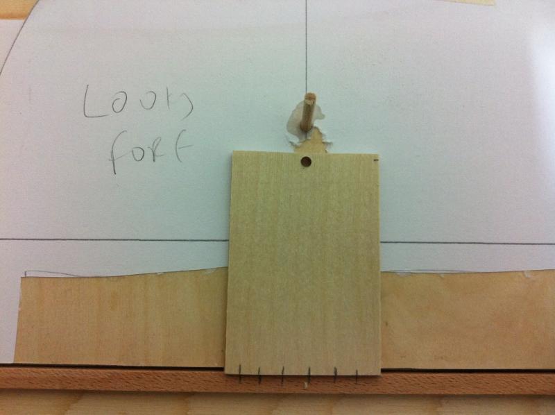
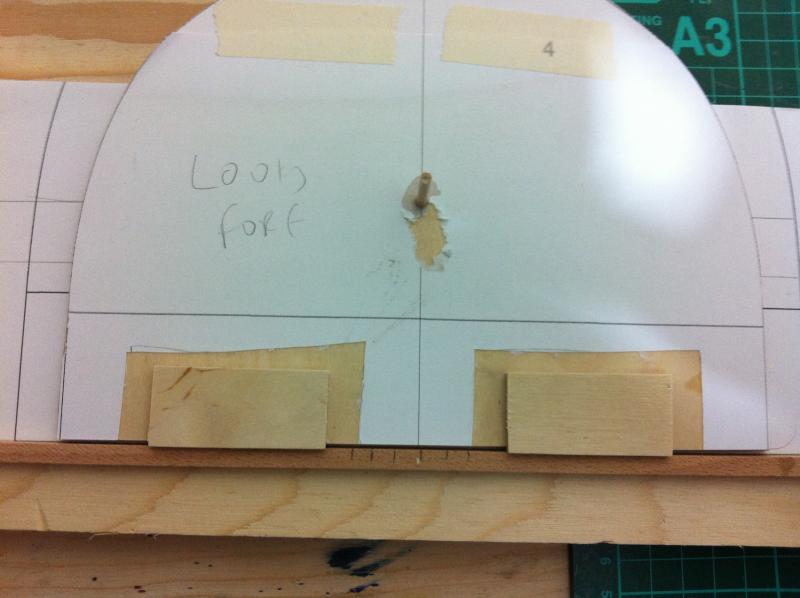
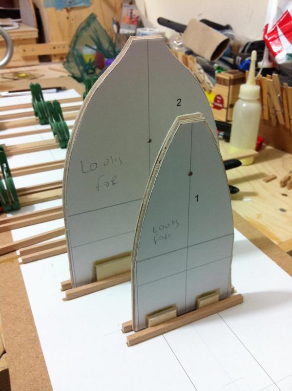
Dear all It has been almost 6 months since my last post showing some progress and this week I was able at last to do some work on the boat. I started converting the garage to a workshop, I built a new bench and upgraded the lights (still not enough though). There are still things missing but overall it is shaping up. The first thing I did was to better sit the keel to the temporary frames as there were previously gaps of several mm. Also, I fixed everything in place with screws and pins, not too securely but when the first planks go in, the structure will be very solid. Next, it was time to tackle again the garboard plank. I started again from scratch. I must admit that none of the available tutorials seems to fully work on this boat. The next photos show a straight strip secured to the frames. The solution was to add small pieces of stiff cardboard continuously, until the right shape was reached. After the upper edge was defined, I used a 1 mm walnut dowel to define the lower edge, so that eyeballing the curve seemed fair, making sure it does nor extend too high up the stem. I then used a compass to transfer the distances from predetermined points at the upper edge. I used a 3x3mm strip as batten to draw the lower edge, then transfer the lines to the maple sheet. I cut the plank and test fitted it onto the boat. Happily, it went on just fine! I do not have enough experience but I think the shape is not far off what it should be. Also, at last I now have a reproducible process I can follow for the rest of the planks. I now need to prepare the other garboard plank, fix both in place, arrange the remaining planks in both sides and complete the planking.


-
Dear Patrick Very nice and stylish work! The master cabin certainly feels luxurious and the wardrobes are a masterpiece! Couldn't help noticing a couple of minor details though: The chair count seems 15 to me! Now the chairs are indeed 14 but there are 13 plates on the table! Dinner arrangements are obviously not finalised yet... I ll be following from the back of the room Patrick Vaddoc
-
Dear all Despite my best intentions I did go into hibernation. And for a good reason: I have been blessed with a second daughter and moved into a new house. So now I have a new baby to play with and a new garage to turn into a shipyard. Everything needs to be unpacked, stuff to find their place, lighting and hopefully some dust management system to be installed etc. I have also started making a new massive work bench in addition to my old one. Progress is bound to be very slow but I will try and keep this log alive. Hopefully, I will be able soon to post some images of the new work space. Regards Vaddoc
-
Dear all Things seem to progress well Druxey thanks for the advice, I laminated the card I have and indeed it works much better as it stiffened up a lot. I finally defined the garboard plank and it fits like a glove on the other side. I decided to redo all the markings on the other side and to go for 17 planks instead of 22, and reshape the garboard plank to allow the planks to curve more and spread better at the bow. I grossly kept the shape of the gb blank and divided two of the widest frames to 16 planks and marked all the other frames by eyeballing the shape of the planks. It did not come out perfect but came out ok. I also reshaped slightly the sheer, after I placed the boat the right way up it was clearly not fair. There is still a problem with the stem, the bottom half seems to be too wide. I ll look into this and then cut all the planks out of greyboard.


-
Thanks Druxey, indeed turning the boat the right way up gives a much better idea how fair the lines run. I finished outlining the shape of the planks, it was surprisingly straightforward and after a while I was able to eyeball the fairness of the curves much easier. I only had to change a few of the original markings. However, transferring this markings to paper proved an extremely difficult job. I found out that using 300 gsm card is the better option. I struggled for days and I think I have one side of one of the garboard planks done. I tried to define the other edge but the result was so wrong I gave up for today! Planking is definitely not easy!


-
Dear all Thank you for your comments and your support! Druxey, I read Antscherl's tutorial and I must say it was really helpful, more so than any other I have read. Patrick, when I saw how large the boat actually is I thought immediately of an RC version. I spend some time thinking how I would do it and I was tempted to go for a cold moulded epoxied 3 layer hull. This will be for later though, I need to build my experience and also I do not have the time (or money) to get into RC technology right now. Mark, I totally agree, in my previous model the lines looked different and much easier to interpret when I turned it the right way up. This is a big girl though and the planking might need to be done upside down. The initial plan was to install temporary battens, then the frames and then turn the right way up and start planking. I still am not sure how I ll do it. I managed to do some more work on the boat and the milestone is now official, the keel assembly is done! I intended to laminate the sternpost knee but I had solid pieces of laminated timber from the previous failed attempt at the keel so I used these. It came out very nice! The whole thing is very rigid, I intended to drill and add some dowels to strengthen the epoxied joints but I think it will be fine. I have not secured the keel to the temp frames but it is reasonably well wedged so I started lining out the planks. There should be 16 planks but I decided to increase the number and go for 22. This way it will be easier to fit the planks to the curved sections of the frames and maybe I will be able to use some of the expensive wood strips I already have. The battens I have are pear 3x3 mm and unfortunately are too rigid for the purpose. I have some 1mm walnut dowels and they proved very useful to determine the curvature of the planks. I first defined the sheer in both sides which was a bit off the CAD markings but appear to run fair. I then divided all the frames that run from the keel to the sheer to 22 segments. I then run a batten along the 11 plank markings (middle of hull) and defined the respective crossings at the rest of the frames, the transom and the stem. I did the same for the plank no 6. The most difficult planks are the planks 1-6 with plank 1 of course being the garboard plank. I fitted the battens making sure they run fair and marked the crossing points. I think it looks ok. The planks open up at the sternpost and transom but so far it looks ok. One think that is missing is fairing. I checked and the frames seem reasonably faired (at least most of the time!). But since I will be installing steam bend frames, even if a frame is off at a plank I think I will be able to make adjustments by sanding or adding material. I will continue with the battens until I mark all planks and then I will cut all the plank patterns out of greybeard.


-
Some more progress, at last I can see the shape of the boat but somehow I feel something is wrong. I finished the stem, the deadwood has been chiseled and sanded to shape and the rabbet completed. I must say it does not look awful! Of course, it needs a massive amount of fairing as after the paint goes on all imperfections will show. I also epoxied the sternpost to the wood keel. I checked it a hundred times to make sure things were reasonably aligned and I think it went in ok. There is some more sanding needed and the transom bevels to be completed but it is almost there. When the transom knee goes on, it will definitely count as a milestone. The whole thing is so big, my old iPhone cannot cope. Despite the frame No 5 looking a bit off, test fitting a couple of battens seemed ok. However, when I tried to define the sheer, I was surprised to see that it was much less curved than I intended. Also, on some frames it was off by 2-3 mm. Maybe it is a trick of the eye, we ll see. I am not sure how to proceed from now on. I intended to fix battens with screws, then put the ribs in place securing them to the battens and then plank progressively removing battens. This is not going to work though. I think I should at this point define the shape of the planks. I will use 2 mm greyboard, maybe it will work ok. I have never done any planking and it looks a rather big job. I tried to roughly divide the hull in three sections but it did the whole job even more intimidating. I must stop being lazy and read a few tutorials more carefully, these certainly are uncharted waters for me.


-
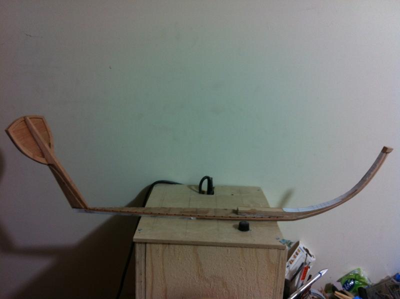
I just had to post this last photo, it is not technically a milestone but sure it feels like one. The sternpost and transom are ready, the bevels are incomplete as they will be finished during planking. It still needs some fine tuning to fit onto the wood keel but test fitting shows it is very close. The stem is ready as well as the wood keel, the rebate line is almost completely cut. Some more sanding is needed to get perfect fit with the metal keel, this will be done after planking as well. in the next photo the wood keel is glued to the stem with very thickened laminating epoxy. All appear well centred, apart from frame No 5 which is off sideways by about 2 mm. No idea how this happened! The sternpost just rests on the frames for the photo, it is not glued yet. I still need to make the sternpost knee. I have included in the photo the metal keel (made of wood!) and the stem dead wood which has no work done to it yet. Finally, after 9 months of work, I can show something that vaguely looks like a boat!
-
Things slowed down a bit so I got an opportunity to work on the boat. Thanks Patrick, still a lot to be done but I think planking is not that far away. All frames are erected, I am happy with the result. The stem is almost ready, I finished the bevels on both sides. I used my new chisels and there is definitely a learning curve, the first side I tackled did not come out as nice, although the planking will cover everything and there is more than enough wood for the planks to sit on. The other side came out perfect. In the plans there is apiece of timber joining the edge of the wood keel with the keel. It seemed easier to laminate a piece using leftover beech strips from the stem lamination. I used the stem as template As there was some leftover epoxy, I also glued the transom to the sternpost Next, after epoxy has cured, I ll fit the wood keel, sternpost and transom, stem and stem deadwood on the frames and epoxy everything together. Then the sternpost knee will be added and holes will be drilled to insert dowels to reinforce everything. Then it will be time for lots of head scratching dealing with the battens, planks and steam bent frames.


-
Indeed Patrick, life has this annoying habit of getting in the way of our boat building…congratulations for hitting this milestone, I think the boat looks great, very nice lines.
-
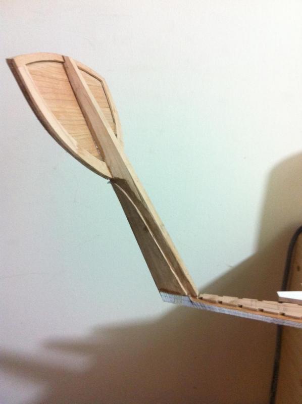
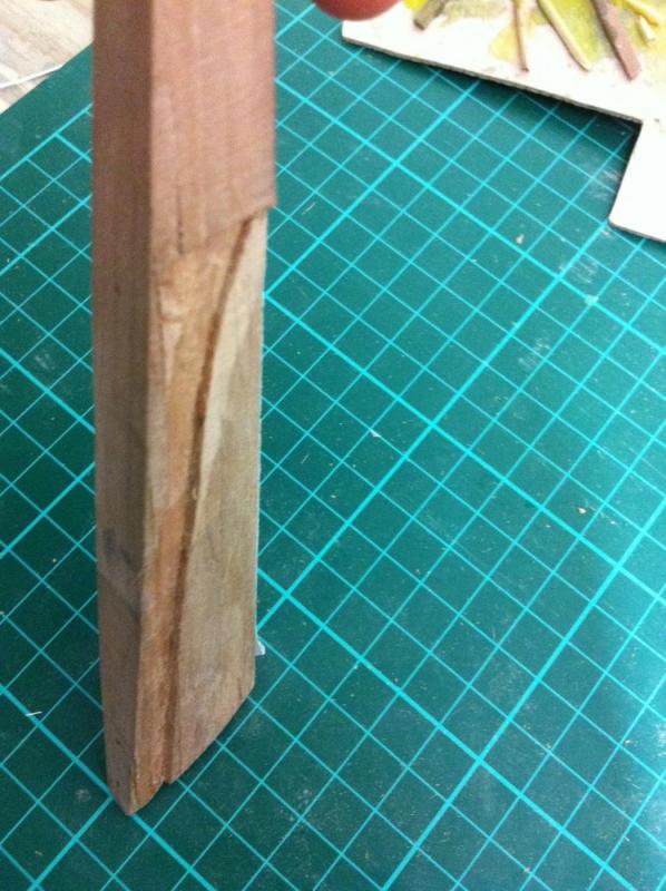
Dear all In the last couple of weeks there has been some definite progress, somehow I found some time to spent on the boat. Very importantly, I think I have at last figured out how the sternpost and the transom work together and how they should be built. First of all, I finished all the temporary frames. They are now cut to the back up base line, following the recent mistake. The dowel previously going through all the frames has been removed and all the spilled epoxy sanded off. A new 3 mm hole has been drilled through all the frames for the new dowel to pass through. I also made the Transom. It is made as in the full scale boat, 4 wide slabs of timber glued together. The sternpost, the transom beams and the planking will bind everything together securely. The stem is also progressing fine. I need to cut the rebate line and also a small piece of timber (as per the plans) to fill a gap between the stem and wood keel. The stem is huge! I have also done a lot of work on the wood keel. It still needs some more work, to fully cut the rebate line, mark the positions of the floors and glue the metal keel on. Then, some more sanding will be needed to mate all the surfaces together. The whole keel assembly is absolutely massive. For the last couple of weeks I have also been thinking about the planking. I read the tutorials that are available but I did not find them very helpful for this particular boat. I also thought about defining the planks on the CAD design. It did kind of worked but I would prefer to plank the old fashion way. I also realised that the way I designed the sternpost was wrong. The following picture shows my sternpost which widens towards the base of the transom. The rebate line follows so it curves outwards. However, the sternpost should be straight and meet the transom. The rebate line should also not curve outwards but just end at the junction of sternpost and transom. When I test fitted the sternest and transom the whole think did not work at all. I decided to reshape the sternpost and slightly the rebate line. Now I think it works much better. Of course, the aft end for a couple of the planks has now been moved inwards so my initial CAD lofting does not apply anymore but there is nothing I can do. Maybe it will not be too significant and with a bit of fairing it might be fine. I also finished cutting the rebate line on the sternpost. The sternpost looks rough but actually it is not too bad. I also cut the transom beams. The upper one has been glued, the others will follow. I think I will need to deal with the planking very soon. although I will use 2 mm cardboard initially, I suspect I will then need several sheets of 2mm maple. Another pricey wood order will be needed, I suspect the admiral will not be very happy! Regards Vaddoc


-
Thanks Michael and Patrick. Indeed, after sanding I am sure it will look like a solid chunk of timber. I now work at a very slow pace. I started re-doing the frames which have now been cut to the back up base line. A new hole needs to be drilled across all frames so that the stabilising dowel can pass through and small pieces of wood to be glued so that all frames sit at the same height. Hopefully I ll be able to do a bit more work in the next couple of weeks
-
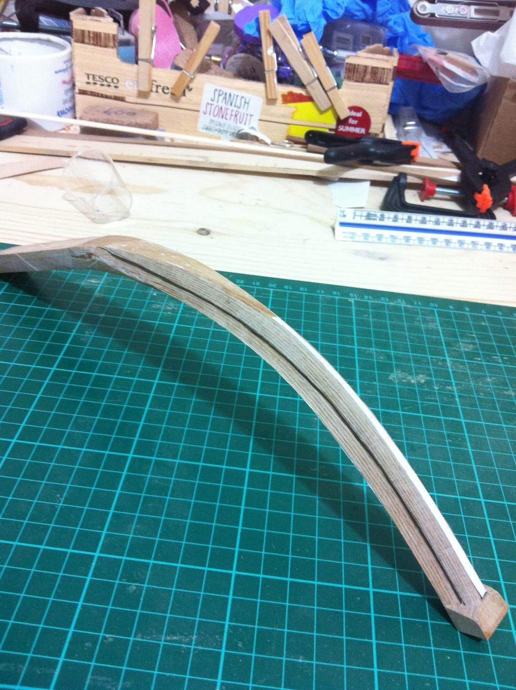
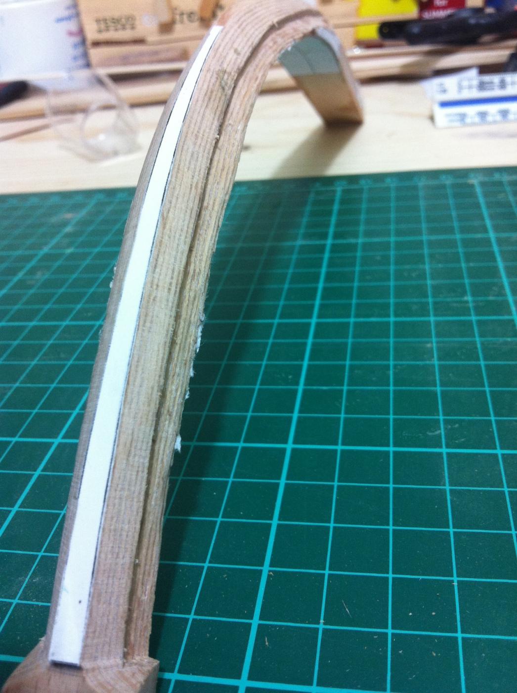
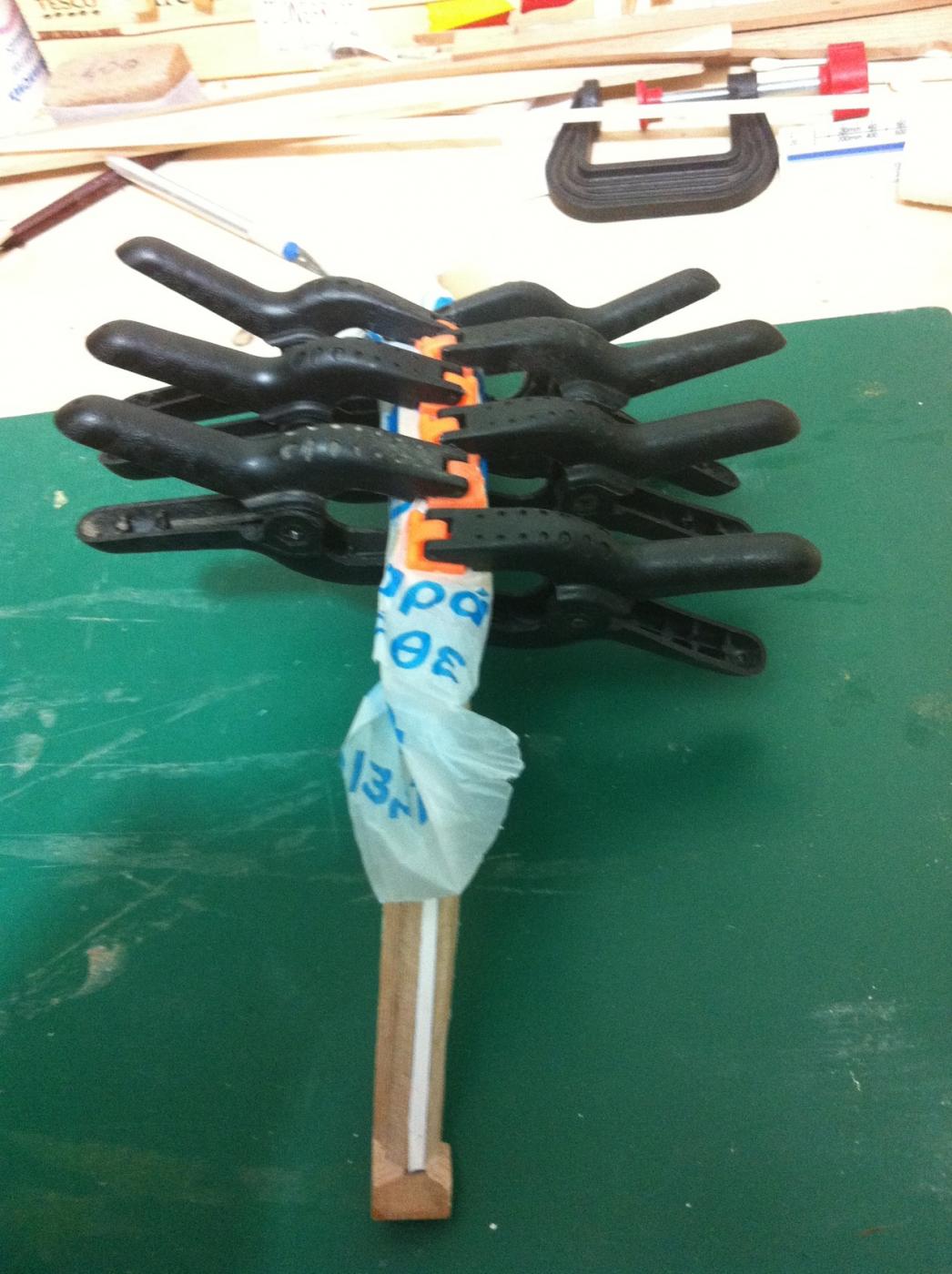
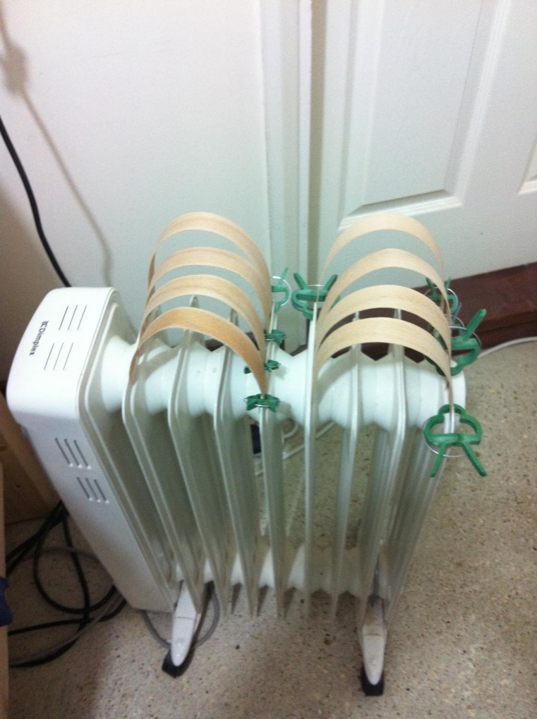
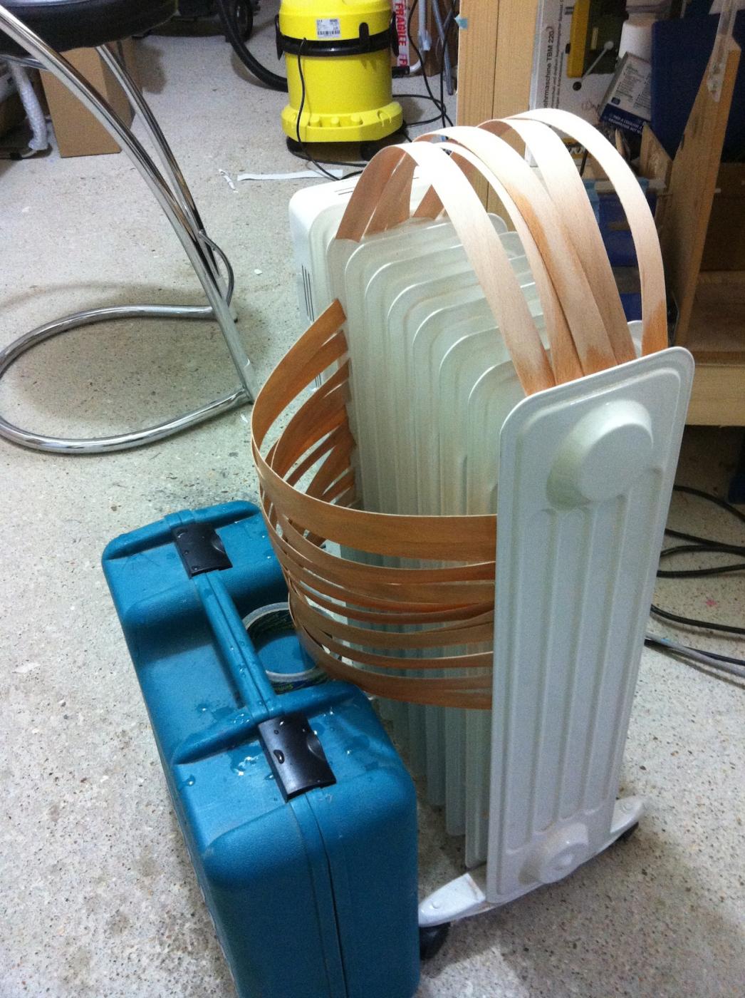
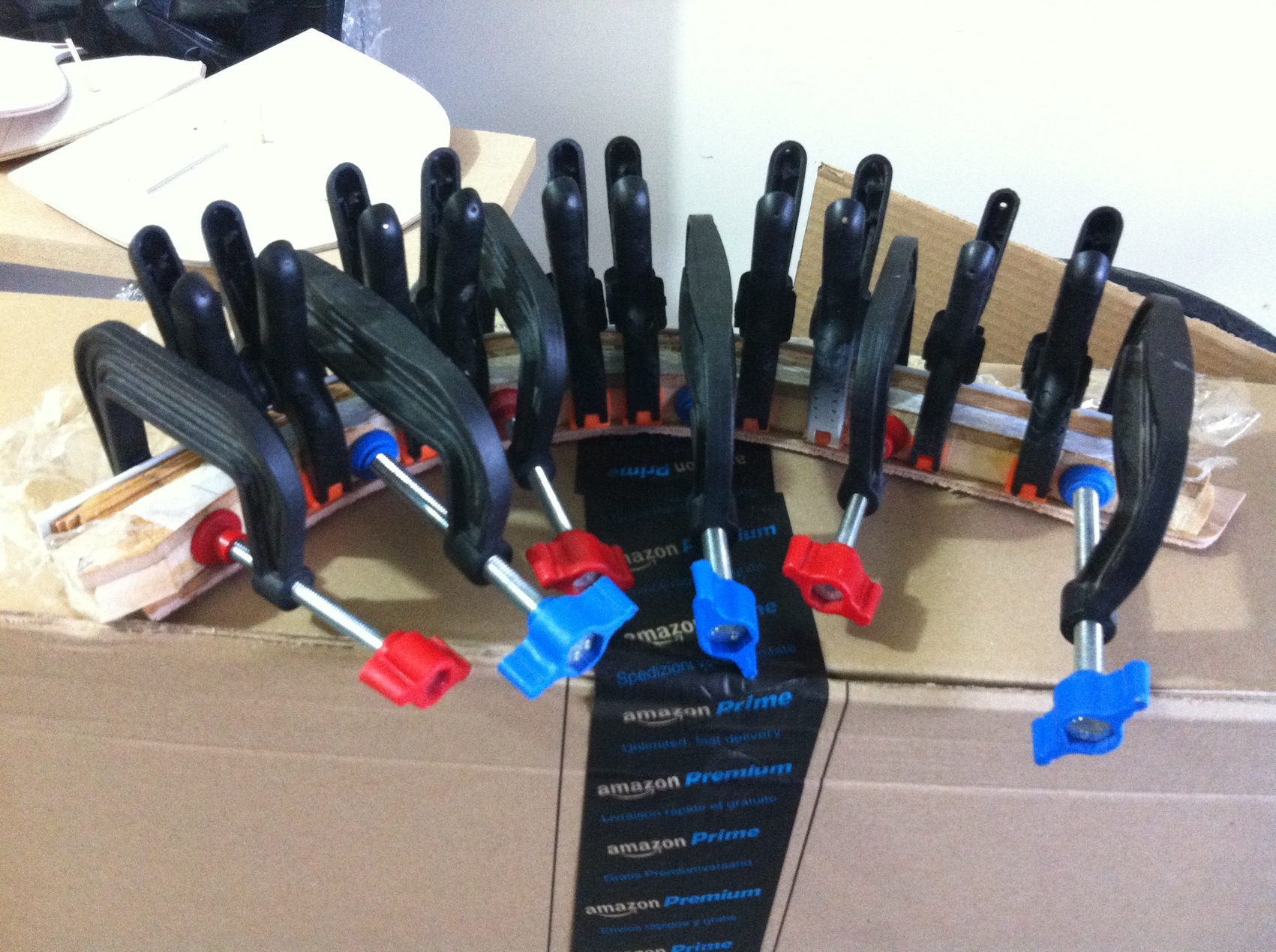
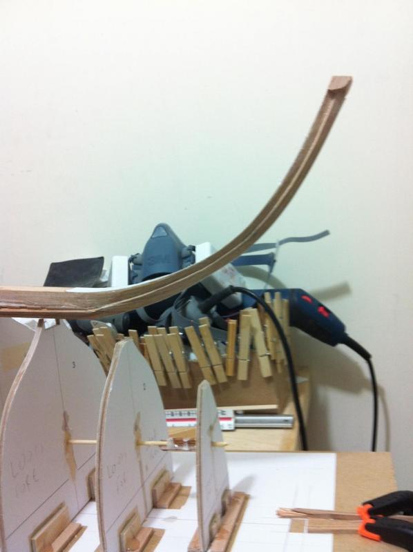
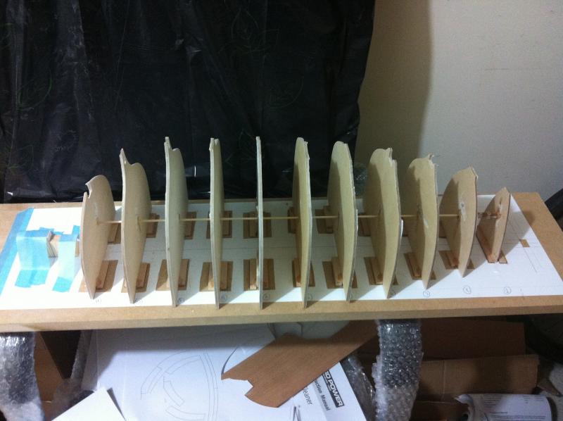
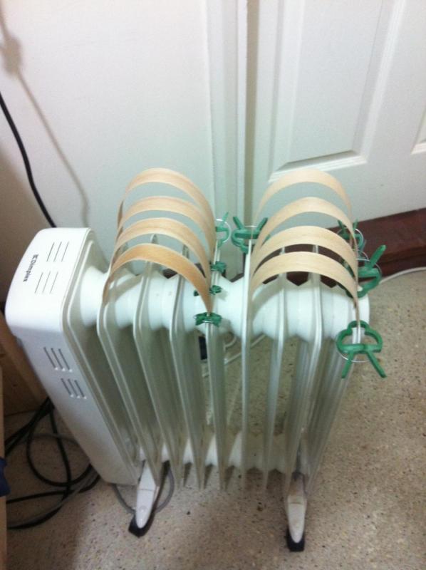
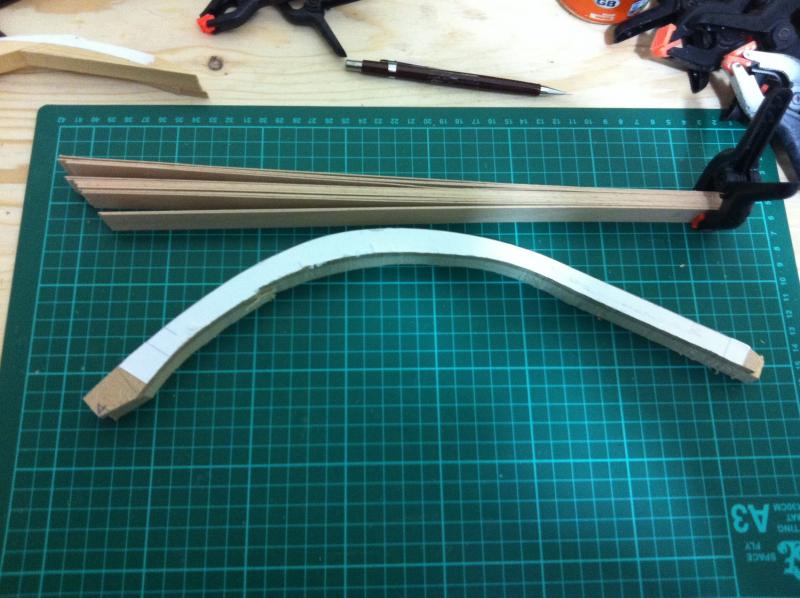
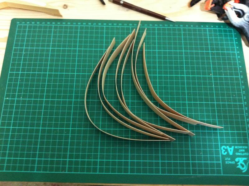
Dear all I have some bad news, I realised I made a mistake. I was trying to test fit the wood keel and it would not line up with the frames. It took me quite a while to realise that 2 of the frames were glued 3.6 mm forward of their position. Considering the 1:10 scale, this would be 3.6 cm in the full size boat, maybe insignificant but there was no doubt in my mind, re do! I had however included in the templates a back up base line so I can reuse the frames. I dismantled everything and cut the frames close to the new baseline. I made a new jig to line up al baselines and mark a new hole to pass a dowel through. I also had to sand off all the epoxy drippings. Lots of work to be done until the frames are again erected. I took a brake from the frames to laminate the stem. It is going to be massive and the jig equally huge. I used scrap pine wood and mdf, my tools reached their limit and from all the power sanding there was a proper mist in the garage. My 3M mask is brilliant though, I was perfectly safe breathing through the filters! With the door open and the air filter full on, the air cleared quickly. I cut the beech strips to length and bent them to shape. Beech is a lovely wood for bending, just wetting the wood makes it very pliable. I thought of using my electric radiator as a jig and it worked brilliantly. After that, I laminated the stem. It needed a massive amount of epoxy thickened with talk powder but so far it looks good but really needs to cure overnight.


- 536 replies
-
- 13
-

-
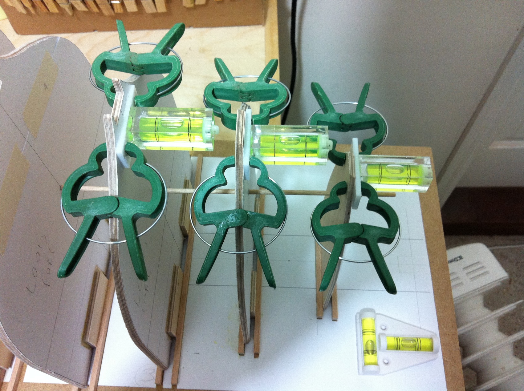
Thank you all! Yes, I suspect building will slow down a lot but I will try not to give up. Another alternative might be to get a monograph of a 2 mast schooner or a frigate (I really want to make a fully frame model one day) and prepare the whole boat on CAD. By the time I am done, both girls (I have also an 1.5 year old) will be well grown up! Regarding the spirit levers, I find these very versatile. I can leave them on and arrange the next frame, and just take a pick and know whether the previous one has shifted out of position. They are small and can fit anywhere. A set square could not be used as there are two thick strips of wood at either side at the base of the frames, plus a lot of epoxy everywhere. And for just a few plywood frames, making a jig seemed too much.
-
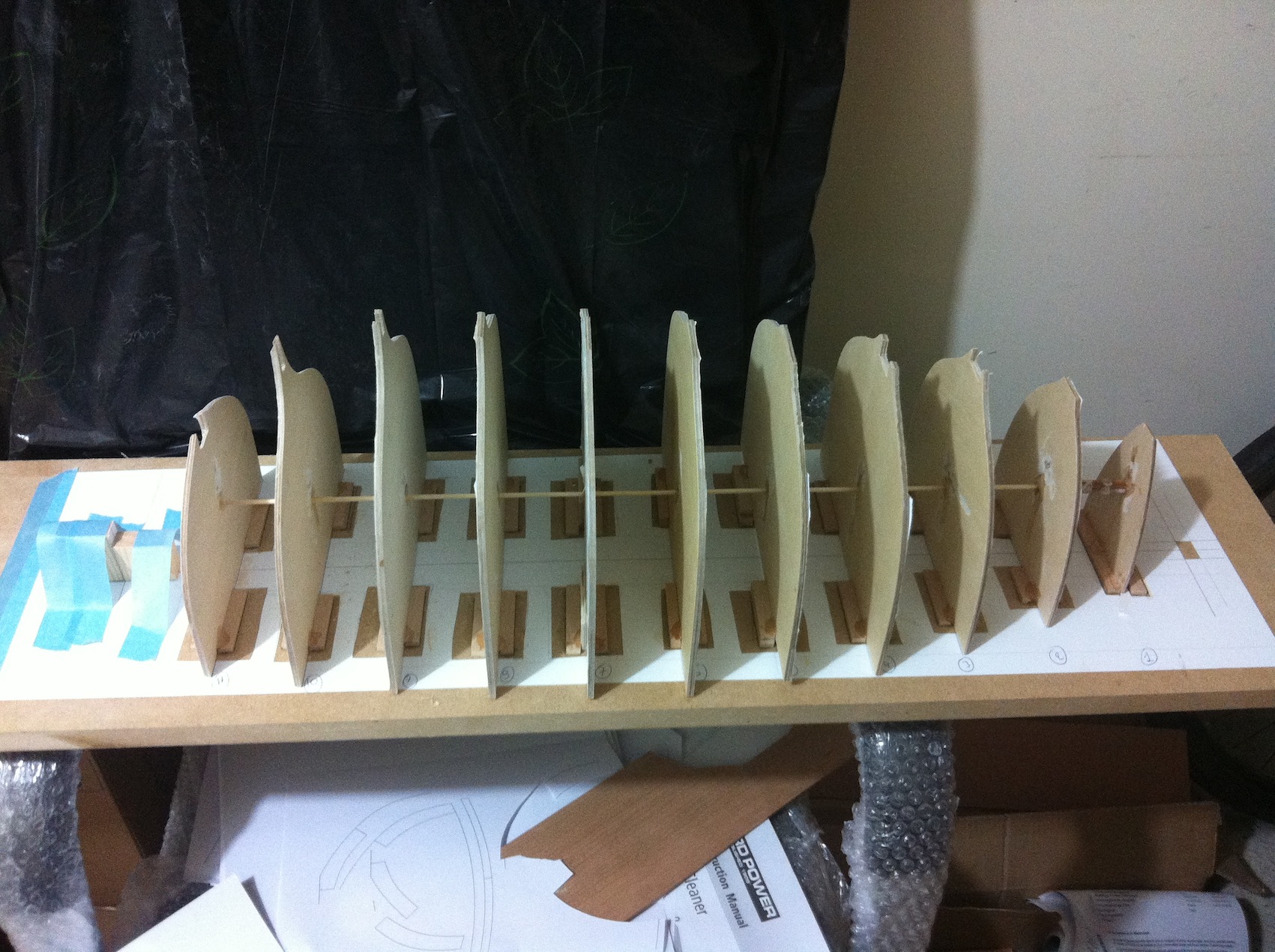
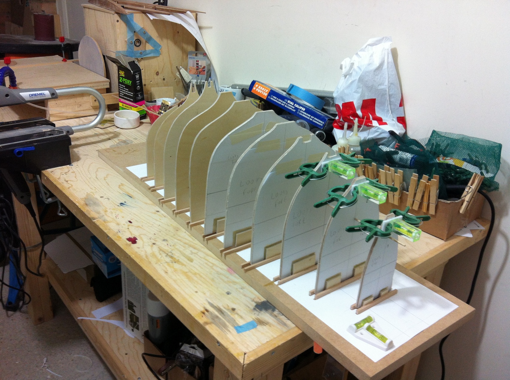
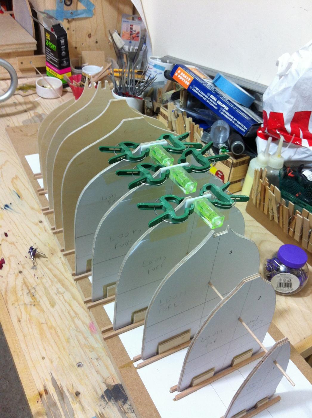
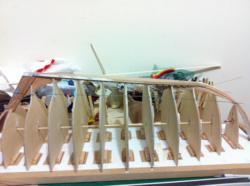
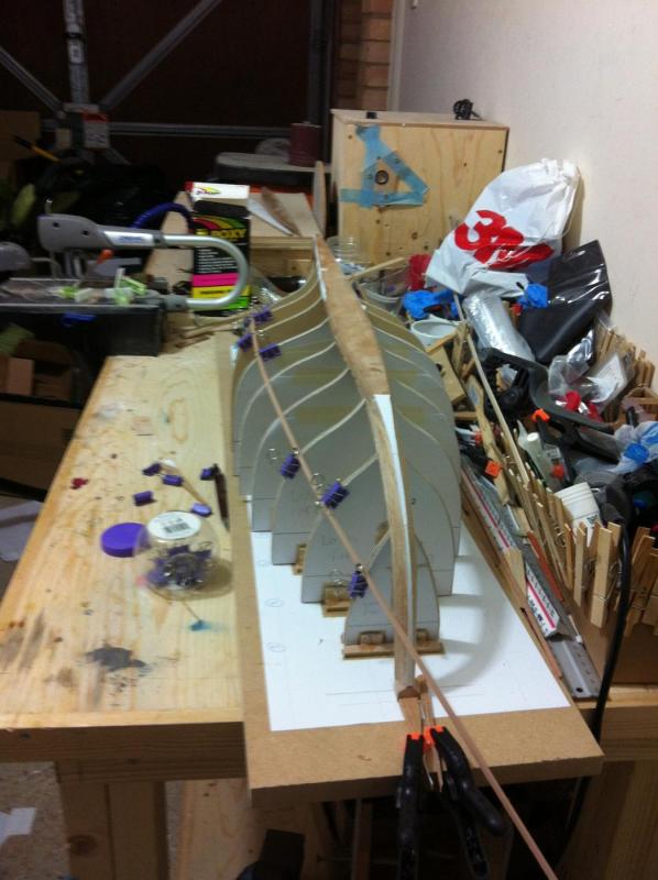
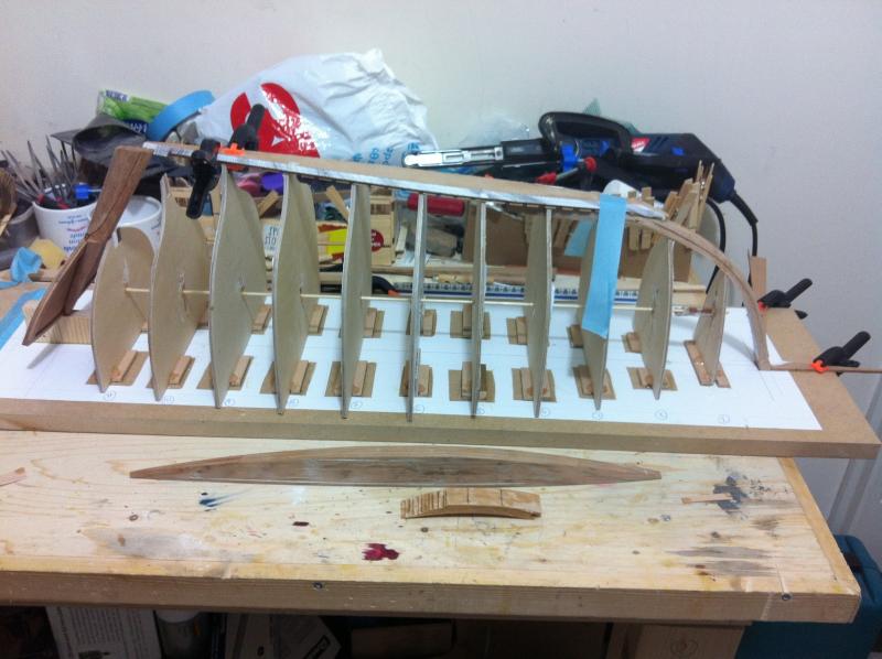
A small milestone reached today, time for another update. Progress has been very slow and with a stork flying again around my house, it is bound to get even slower! It is important for the temporary frames to be firmly fixed in place as there will be a lot of pressure applied with all the battens, ribs etc. The best way probably would be to epoxy everything down. I used a flat piece of MDF and glued the paper pattern, cutting windows to expose the mdf so that PVA and epoxy could stick. It took a while but worked ok. Then I installed the frames, some needing a bit of sanding as the fit was very tight. A dowel running through all frames make the whole thing very rigid. I used spirit levers I modified to make sure the frames are vertical. A couple came out a few degrees off but it will not really affect anything. I attached a few strips and they seem to lie ok. However the planks will definitely need spilling which I thought I might do without. I attached the 3x3 mm pear strips I intend to use as battens. The stern and transom are missing but the hull seems very fair. Towards the bow the battens changes direction but this I think is fine as this is the shape of the hull in the plans. As I have the whole boat on CAD, I think it makes more sense to spill and define all planks, then cut patterns out of cardboard and test the fit. I hope this will work out with only minor adjustments needed. Then I could install the battens, then install the ribs and start planking, progressively removing battens and nailing ribs.


-
Dear all I am about to laminate the stem and I would like your thoughts whether I could use PVA glue. The boat is 1:10 scale, there will be 14 laminates, each 0.5 mm thick and 20 mm wide. It will be a big stem! I can use epoxy and I am sure it will come out fine with no spring back. However, working with epoxy is a dirty business, takes ages to dry and it will be a very hard stem, difficult to cut bevels etc. Could I use PVA? Will there be appreciable spring back, glue starved areas, will the short opening time be a problem and will it be strong enough? Vaddoc
- 3 replies
-
- 1
-
-
- Laminating
- epoxy
- (and 1 more)