HOLIDAY DONATION DRIVE - SUPPORT MSW - DO YOUR PART TO KEEP THIS GREAT FORUM GOING! (89 donations so far out of 49,000 members - C'mon guys!)
×

catopower
-
Posts
1,896 -
Joined
-
Last visited
Content Type
Profiles
Forums
Gallery
Events
Everything posted by catopower
-
grsjax, I've been scouring the Internet for more than a year for Japanese wooden boat/ship model kits. If you check my Tosa Wasen build, that kit is the only non-Woody Joe wooden boat kit that I'm aware of from Japan. Clare
-

1/10-scale Japanese Fishing Boat kit from Thermal Studios
catopower replied to catopower's topic in Wood ship model kits
Wefalck, Actually, some of what was recorded by Pâris seems very good . What kind of craft are you looking for? Douglas Brooks has a few drawings of small boats in his book. You might also try contacting him about more comprehensive plans of the watercraft he studied. You can contact him through his website at http://www.douglasbrooksboatbuilding.com. Beyond that, I doubt you'll find much. Japanese boatbuilding traditions didn't include the use of plans the way we're accustomed to in western traditions. Also, I don't think there's a great deal of interest in preserving this kind of information in modern Japanese society, except among a small handful of people. Clare -
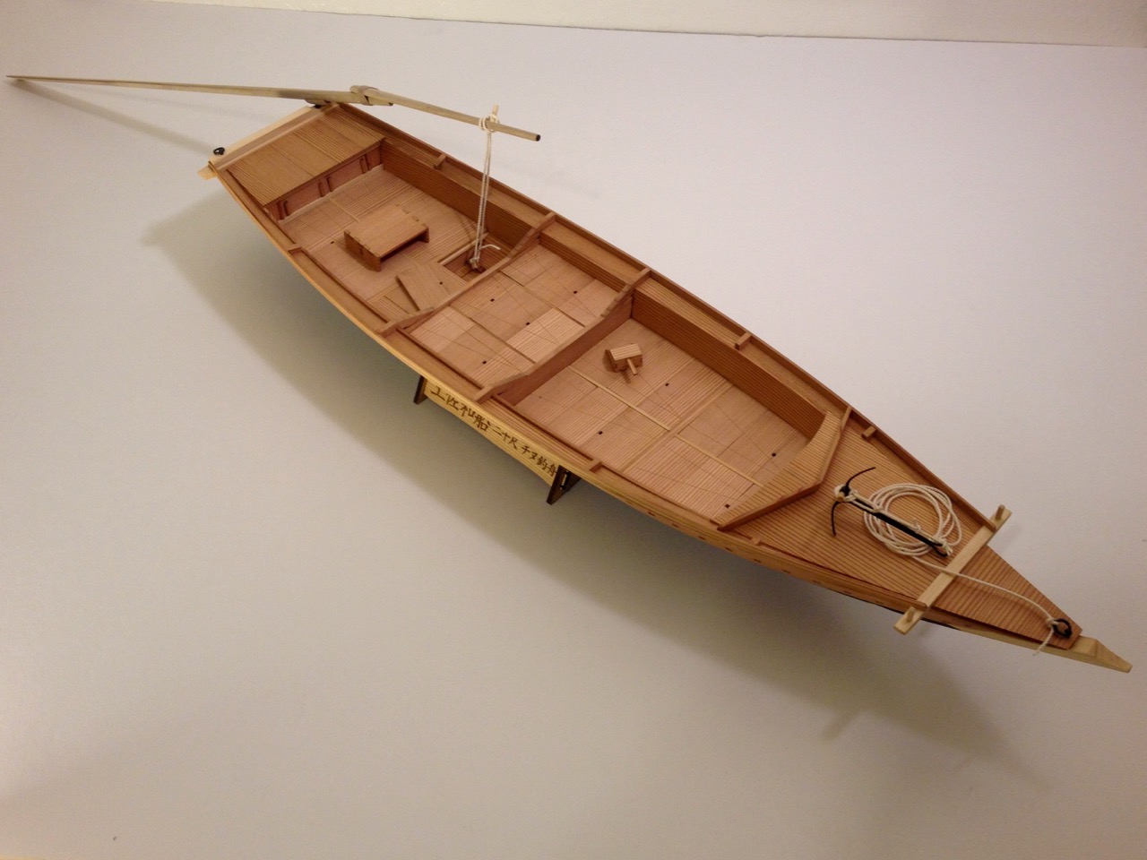
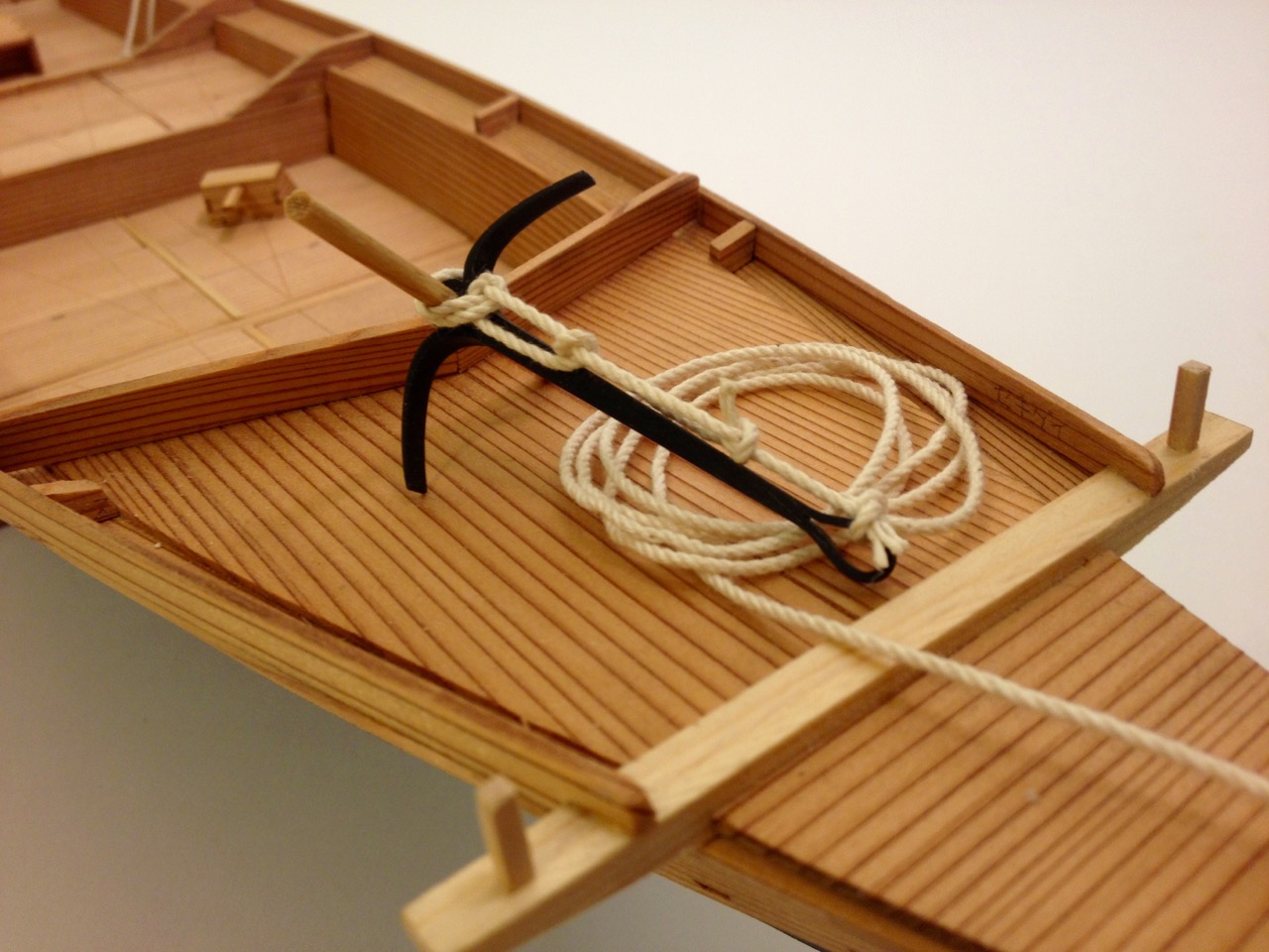
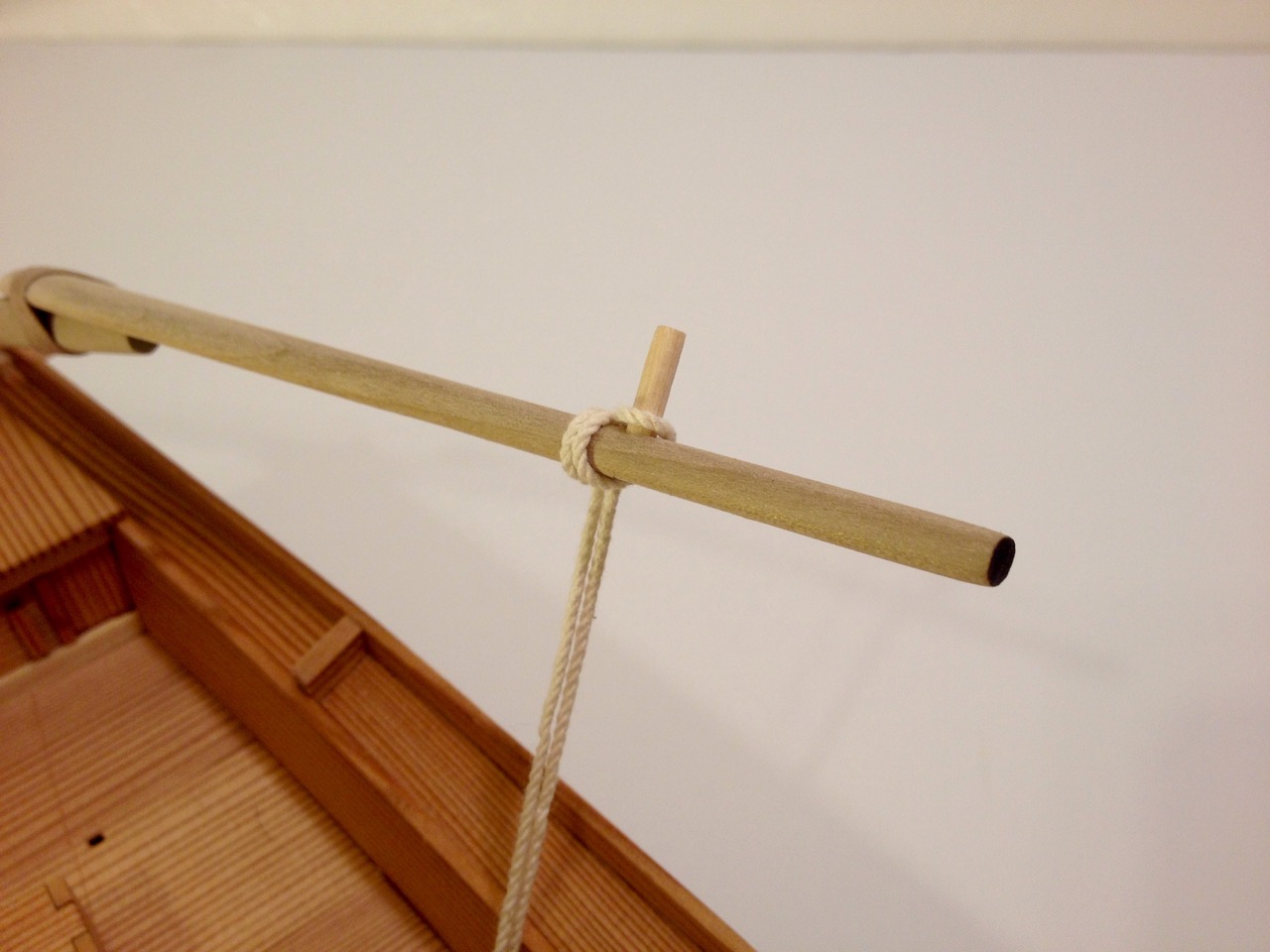
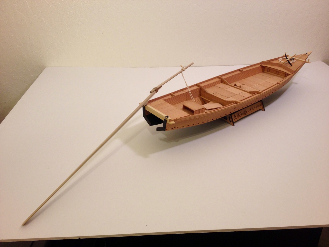
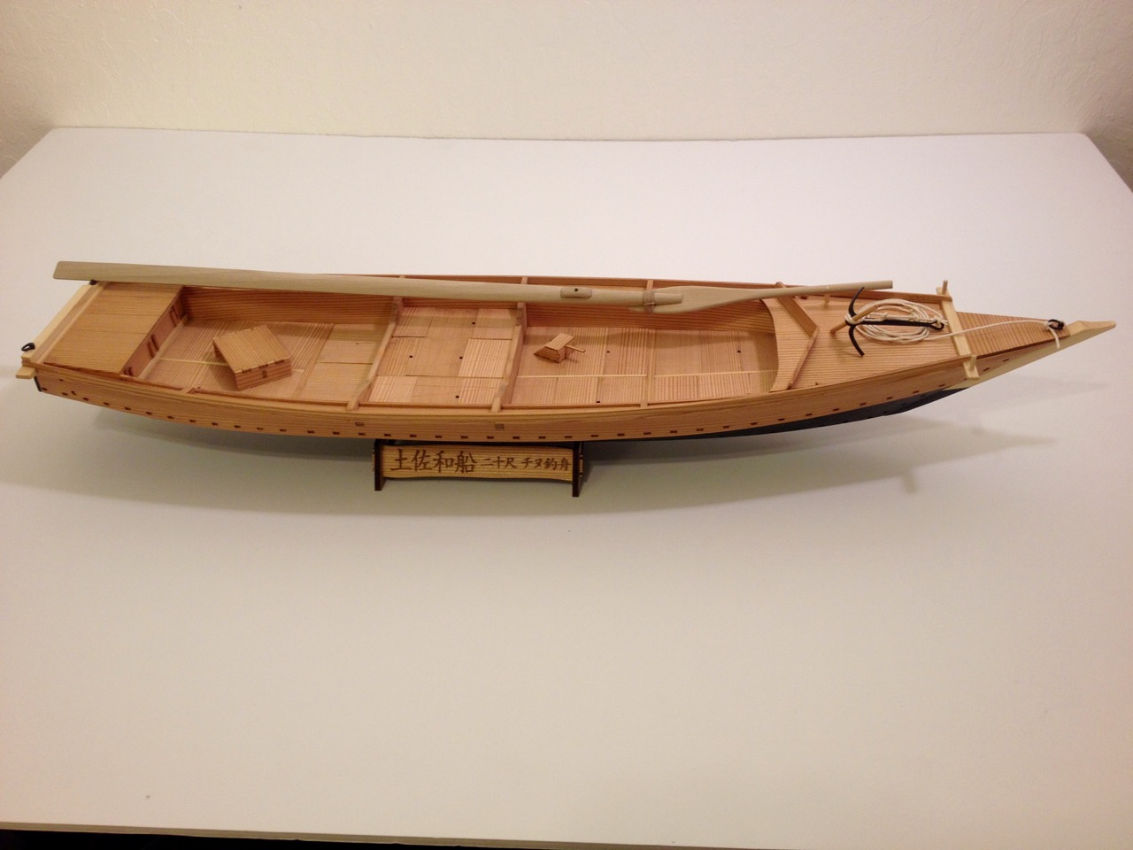
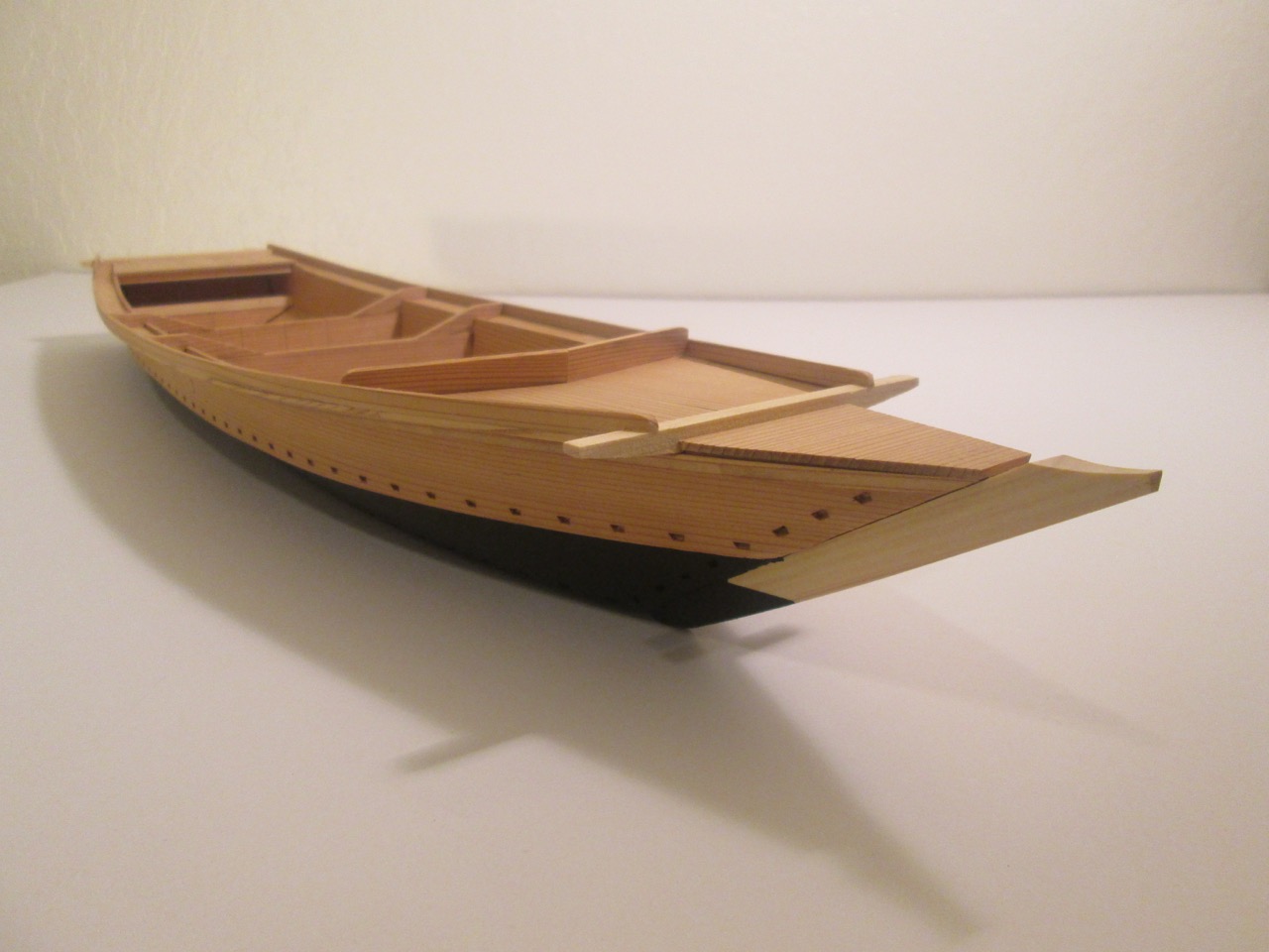
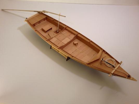
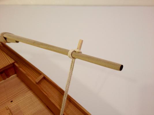
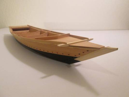
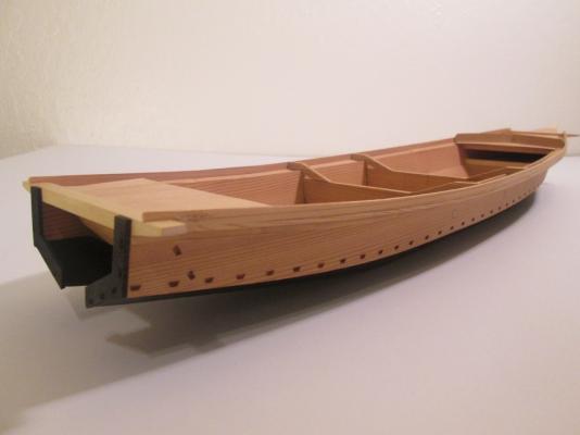
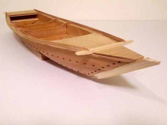
Here it is, the final entry on the Tosa Wasen build. I took a little time figuring out the knots used for the anchor, which had a Japanese name. Also, I wanted the model to represent an Edo period boat, though I couldn't find any information of the exact age of this design. In fact, this small fishing boats of the Tosa region were built to the needs of the individual and there were many boat builders, so there were probably many variations. But, the model is done and I'll figure out how I want to display it next. As you can see, with the Ro in place (the long sculling oar), the model is quite long. With it in the stowed position, it's 2' long. With no masts, it will fit easily on a bookcase shelf, unlike most of my other models. This has been a really interesting build and great kit for those who don't want to go as far as using Douglas Brooks' drawings and the information in his book to try to scratch building a traditional Japanese boat. I think this is about as close as you're ever going to get in a kit. Still, I'd recommend reading his book while building this kit, to really get the fullest experience. I plan on bringing this to the NRG Conference in San Diego this Fall. So, hopefully, ship modelers who don't get around to trying out this kit can see it in person. But, if you're interested in building this kit, don't wait. Here again is the contact info for buying the kit from the manufacturer who seems very happy to sell to faraway customers, payment via Paypal. Email Mr. Tanimura at: Thermal-Studio Website: Thermal-Studio (remember the boat kit is not listed – They manufacture glider kits) If you contact Tanimura-san, please say hello for me. Also, be sure to check out Mr. Toshihiko Shibafuji, who assisted with the design of the kit: http://wave.ap.teacup.com/wasennfunadaiku/ Hope to see some more of these in build logs here on MSW soon. (Yeah, I'm thinking about you, Bob) Clare


- 51 replies
-
- 14
-

-
- wasen
- thermal studio
- (and 1 more)
-
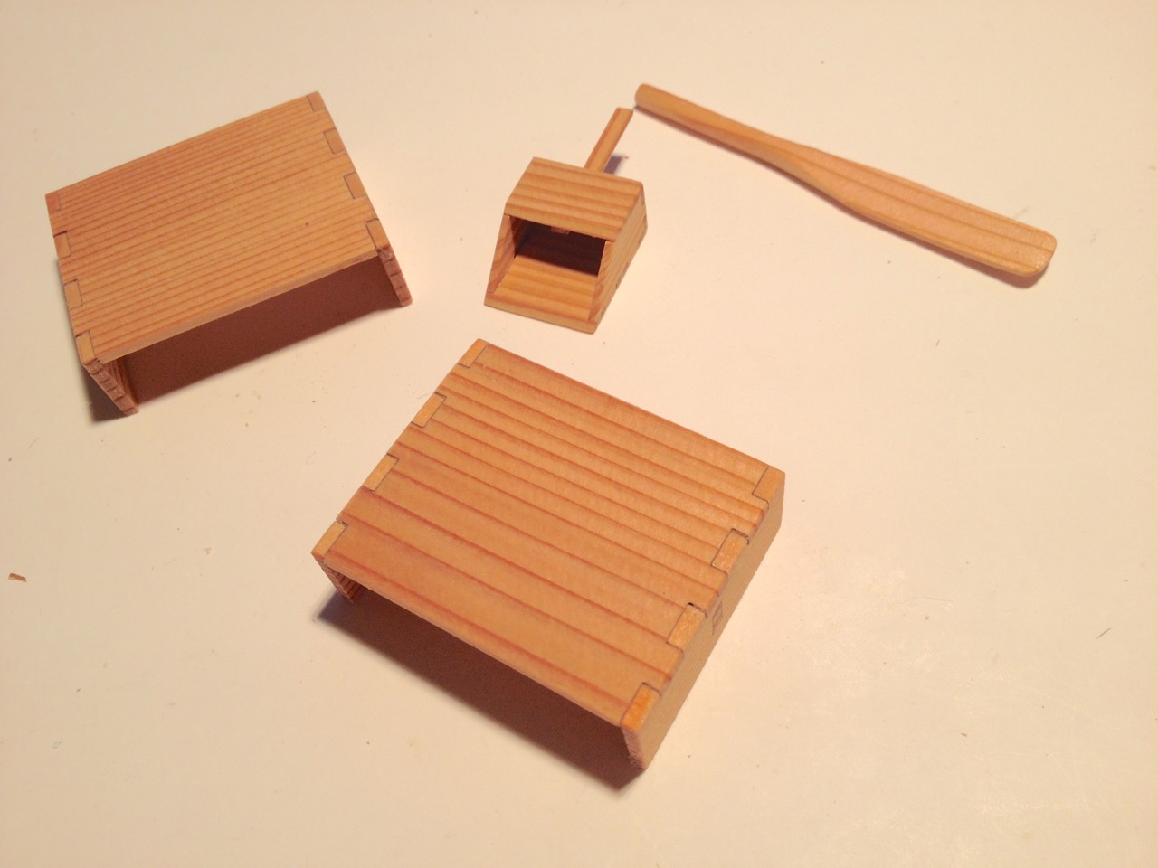
While I'm at, I thought I'd go ahead and post some pictures of some of the accessories included in the kit. These include a bailer, a small paddle, and a pair of wooden seats. These were a fun and easy part of the build and add some life to the model. In earlier pics, to get them out of the way, I just put them into the compartments under the deck. Getting close to the finish now. Should be done in the next one or two posts... Clare


- 51 replies
-
- 13
-
-
- wasen
- thermal studio
- (and 1 more)
-
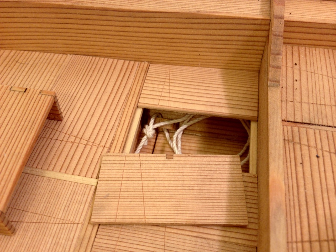
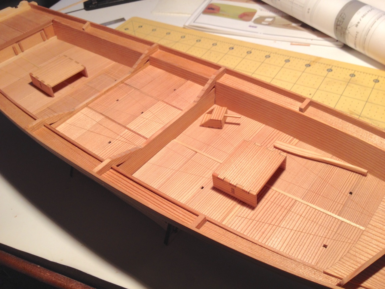
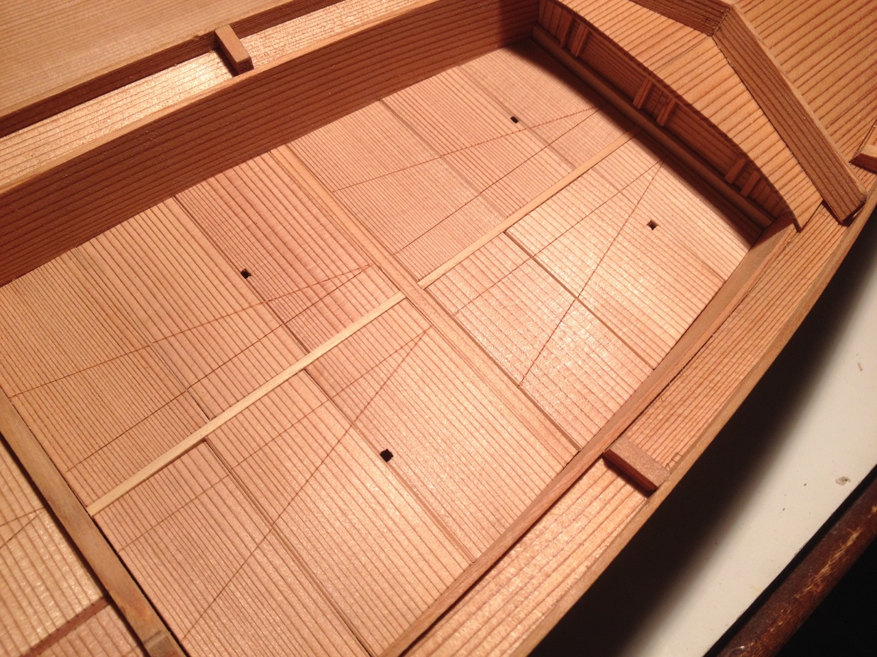
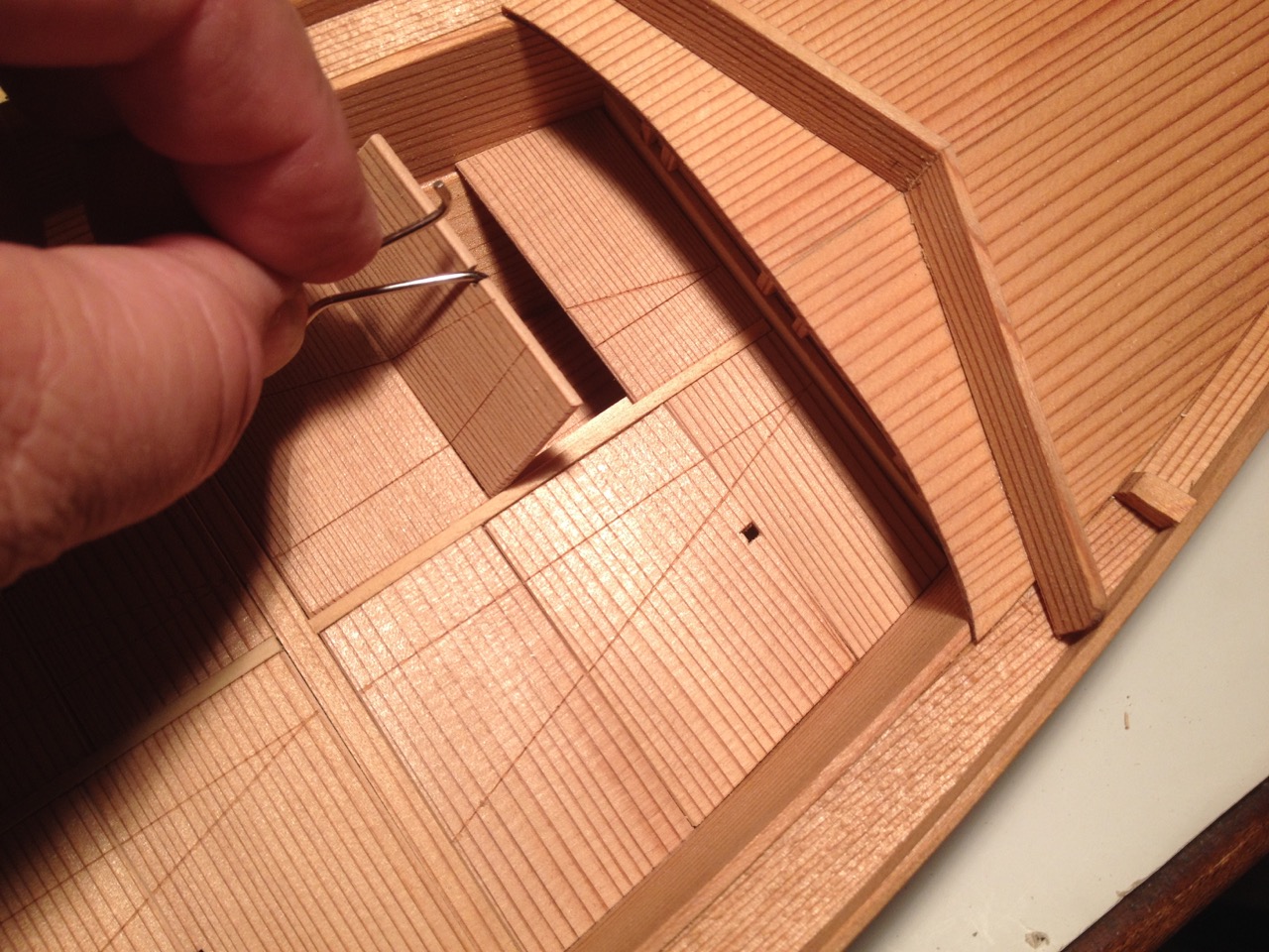
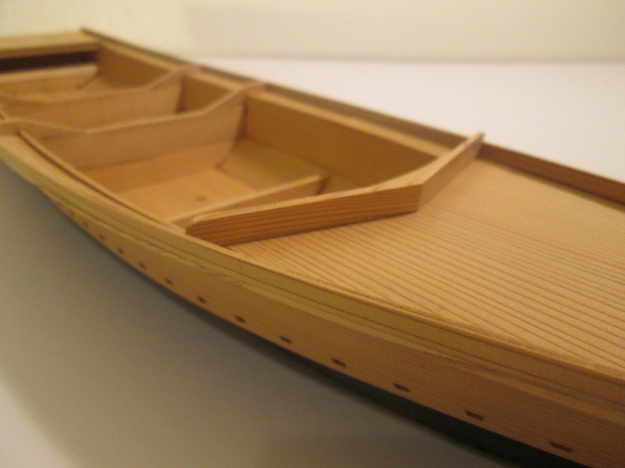
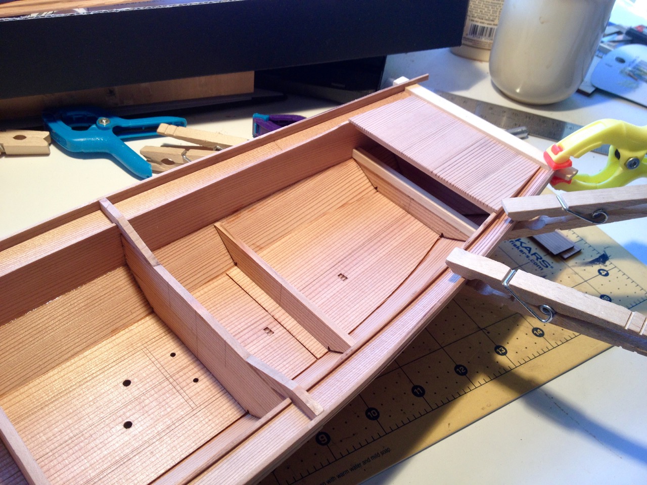
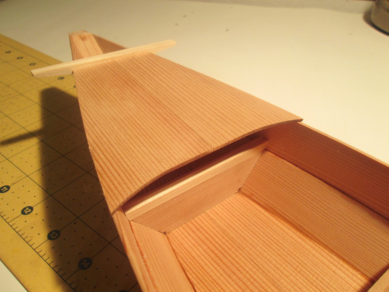
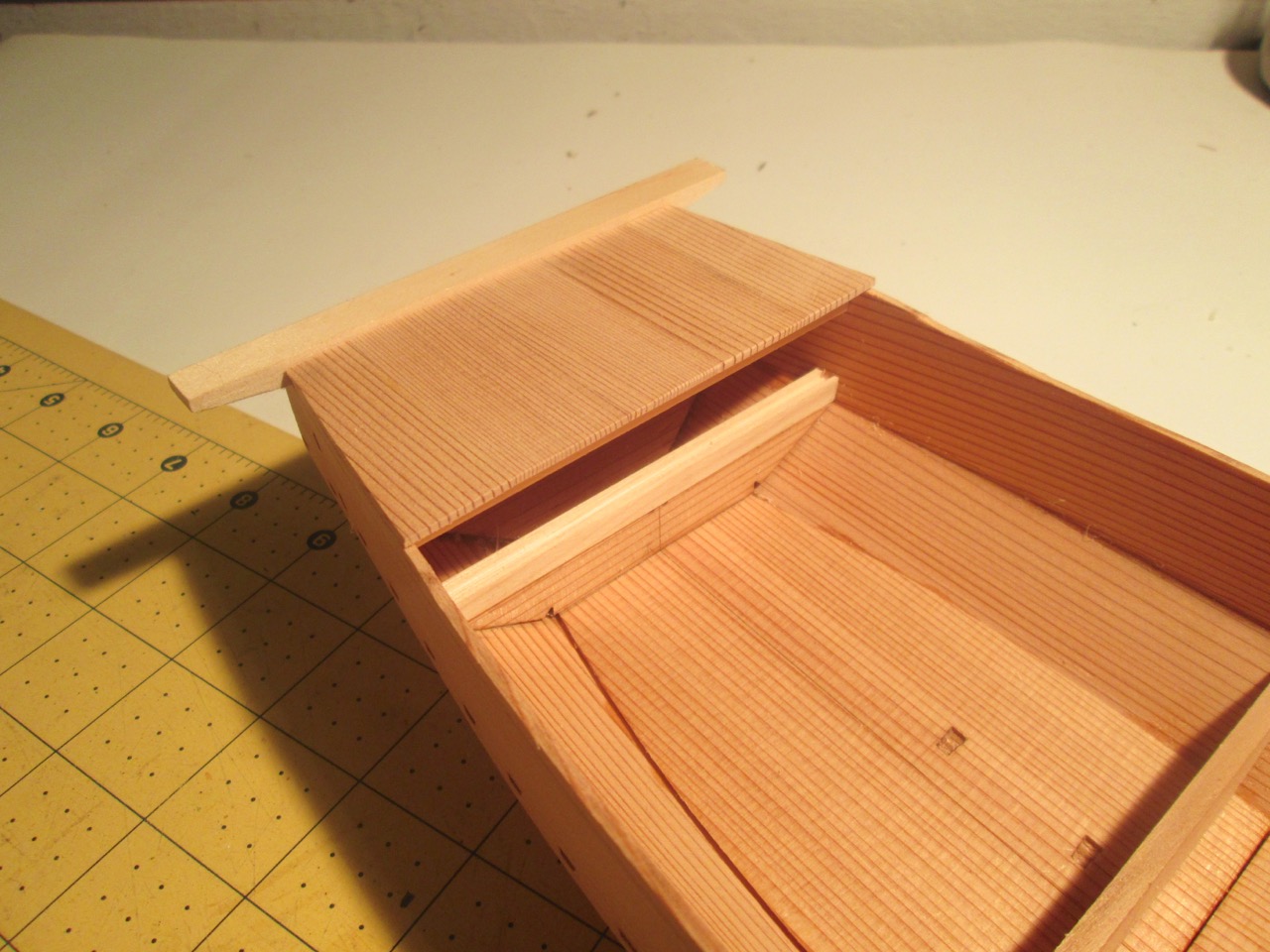
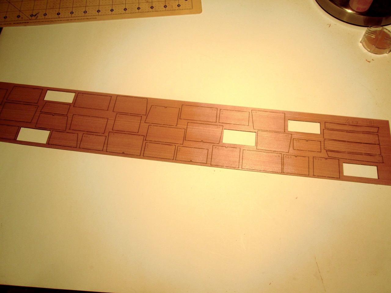
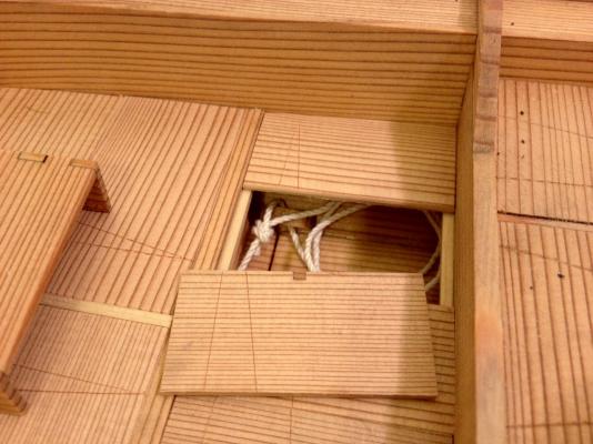
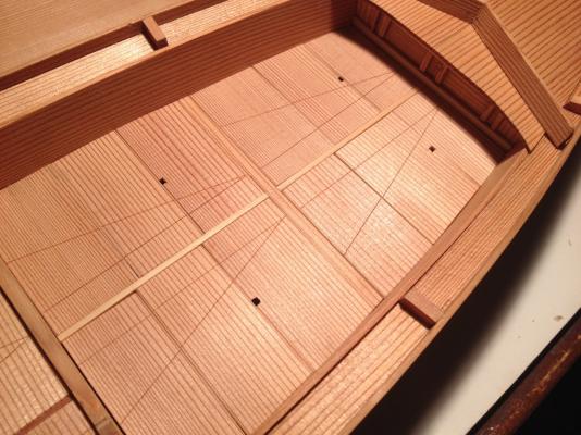
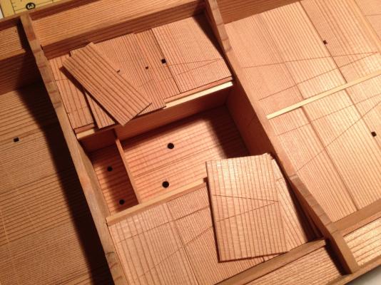
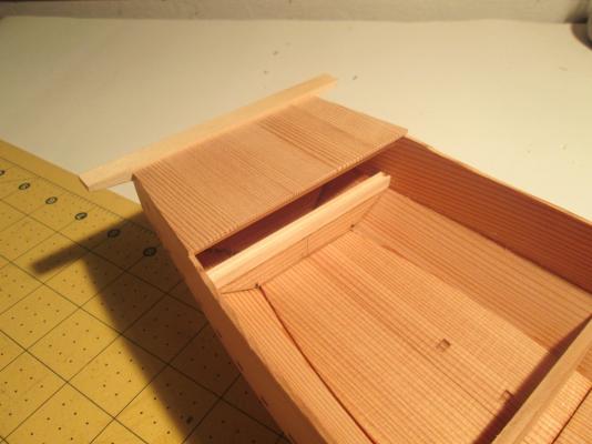
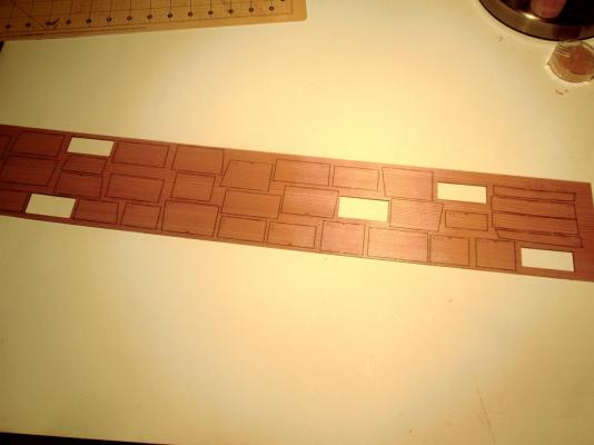
The next step in construction of the Tosa Wasen kit is to add the deck boards. This part of the build turned out to be a lot tricker than I'd expected. This is an area where you really want to take your time, and it's easy to want to rush through it. The deck boards serve as a deck to walk (or sit) on and work on, but they are also designed to be removable, allowing the fisherman access to storage space under the deck. This allows the deck to be kept clear and free of clutter, making for a tidy looking boat. Beam supports glued into place. The beams are sanded to fit, but I left them unglued, so they'll remain removable. Ledges are then cut to length and glued to the beams for the deck boards to rest upon. The deck boards themselves are rather interesting in that they are made such that almost no two are alike. Each one can only fit in one location, with the possible exception of the boards that cover the live wells in the center of the boat. But, given that there are many boards, it would seem to be something of a puzzle trying to figure out which one fits where. To make the positioning more obvious, there are two lines scribed into the top of the boards. The lines form a sort of an arrowhead with the point at the front of the forward most board, and each compartment has a 3 or more deck boards covering it, with its own arrowhead pattern scribed on it. This makes for a quick recognition of the order of the deck boards and also makes it easier to keep from mixing them up. Note that at least one deck board of each set has a square notch cut into one edge that serves as a finger hole to make it easier to pull up the board. The kit supplies the deck boards as laser-cut pieces, which look they'd make it easy to put them into place. However, in order to allow some variation between models, these parts are cut over-sized, so they have to be sanded to fit. This turned out to be a far trickier than I'd expected, as the Japanese cedar is pretty soft, and really wanted to avoid small gaps between boards. In fact, I used every scrap piece of cedar that I could find in the kit in order to finish the deck boards. If you're building this kit, Proceed Very Carefully here The next step was to scribe the patterns into the deck boards. I found it easiest to take each group of deck boards which are part of the same pattern set and marking the endpoints on the first and last board, then scribing them all together as a group. I lined them up against a straight edge to keep them in alignment. This was pretty much the last of the difficult work. There is one more step that was a little tricky, but in a completely different way, and that was the next step. For those following along with the kit instructions, this is step 33. This involves the construction of the covers for the cargo compartments in the bow and the stern of the boat. If you haven't built the model kit yet, I would suggest doing this work in steps 17 and 18 before the compartments are decked over. It would just be a lot easier. I'm not positive why the kit has you build the compartment covers now instead of earlier in the build. Possibly, it's because the real boat would probably be built in the order shown in the kit. That would be okay, except that trying to reach in with your finger and thumb to get the covers into place without knocking parts into the compartments is pretty difficult. The kit includes a small pair of wooden tweezers that you're instructed to build for handling those compartment doors. In the long run, these will be necessary in order to be able to remove or replace these doors without damaging the wood. Clare


- 51 replies
-
- 7
-
-
- wasen
- thermal studio
- (and 1 more)
-
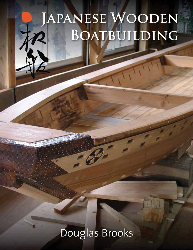
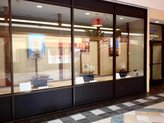
Happy New Year All! Well, I have made a little more progress on the Tosa Wasen, but I'll post that later. For now, I'm taking a moment to mention that if you're in San Francisco, my wasen model display in Japantown has been extended through January. It's in the Japan Center's East Mall building, in the window of Union Bank's community room. The next one I imagine will be in late Spring perhaps. It all depends on what others have scheduled for the display window. But, rest assured the next one will include the Tosa Wasen. Also, with the start of the new year, I thought I'd take a moment to plug Douglas Brooks' book, Traditional Japanese Boatbuilding. This won't tell you step-by-step how to build a Japanese boat, but it will give you all the background about traditional Japanese boatbuilding, materials and tools used, and you can see some of the techniques used and read about Mr. Brooks' five apprenticeships with some of the rapidly disappearing master boat builders of Japan. I recommend ordering the book direct from the author's website as all profits go to helping support research instead of supporting the resellers (not that there's anything wrong with resellers). Here the link: douglasbrooksboatbuilding.com Clare

- 51 replies
-
- 3
-
-
- wasen
- thermal studio
- (and 1 more)
-
Hi Bob, That's great news. Of course, judging from your Higaki Kaisen model, you're final model will probably look better than mine. Anyway, I'm hoping they get a lot of international sales for this kit now. Clare
- 51 replies
-
- 4
-
-
- wasen
- thermal studio
- (and 1 more)
-
1/10-scale Japanese Fishing Boat kit from Thermal Studios
catopower replied to catopower's topic in Wood ship model kits
I posted this in my build log, but it makes sense to put the info here too. Buying the Tosa Wasen Kit If you're looking to buy the kit, there is a faster, less expensive method than trying to get it through Amazon-Japan where I got mine. I found out that you can buy it from the manufacturer for a very good price. To buy from the manufacturer, send an email to the company: info@thermal-kobo.jp. Price for the kit is 13,000 Yen Shipping is via EMS (A Chinese Express Mail Service that ends with a USPS delivery) for 2,400 Yen Payment has to be via Paypal, sending to the email address above. This is a really good price. Makes the whole thing with express shipping only about $130. I went ahead and ordered a second kit. The only thing that I'm not so sure about is that the kit is shipped in its own box, but wrapped with a bubblewrap bag. It's a long box, so it seems like it would be easy to bend in half. But, I received the first kit this way and it was delivered just fine. Then again, I generally have good experiences with the US Postal Service here. It looks like I might have been their first international sale as the owner posted a picture of the kit shipping out to the USA on their Facebook page. I hope he sells a lot of kits! Clare -
Thanks very much John and S.Coleman! Buying the Tosa Wasen Kit Okay, so here it is... I have some information for those looking to buy the kit. First, there's the hard way and more expensive way, which is through Amazon-Japan, as I described and where I got mine. The second is direct from the manufacturer for a very good price. To buy from the manufacturer, send an email to the company: info@thermal-kobo.jp. Price for the kit is 13,000 Yen Shipping is via EMS (A Chinese Express Mail Service that ends with a USPS delivery) for 2,400 Yen Payment has to be via Paypal, sending to the email address above. This is a really good price. Makes the whole thing with express shipping only about $130. I went ahead and ordered a second kit. The only thing that I'm not so sure about is that the kit is shipped in its own box, but wrapped with a bubblewrap bag. It's a long box, so it seems like it would be easy to bend in half. But, I received the first kit this way and it was delivered just fine. Then again, I generally have good experiences with the US Postal Service here. Clare
- 51 replies
-
- 5
-
-
- wasen
- thermal studio
- (and 1 more)
-
Hi Mark, Glad to hear about the arrival of the Hacchoro. I'm sure you're going to really like building that kit! Looks great on the shelf too with the sails and all the oars. Clare
- 51 replies
-
- 1
-
-
- wasen
- thermal studio
- (and 1 more)
-
Hi Peter, Darren, I'm working on it. Before you try to buy one, make sure to read through this topic and also this: http://modelshipworld.com/index.php/topic/12018-110-scale-japanese-fishing-boat-kit-from-thermal-studios/ After about a year of searching and thinking this was a discontinued kit, I had to buy mine on Amazon.co.jp here: http://www.amazon.co.jp/サーマル工房-木製模型-土佐和船-二十尺チヌ釣舟/dp/B0070HU3KI/ref=sr_1_1?ie=UTF8&qid=1451347724&sr=8-1&keywords=土佐和船 This required using a third party to handle the international shipping. The manufacturer's site is http://www.thermal-kobo.jp. It doesn't have a web shop and the kit is not even shown as one of their products. I'm trying to find out if they are willing to sell regularly to international customers. The Amazon.co.jp shop sells one-at-a-time (inventory = 1), and Zootoyz.jp has been unable to get information about carrying the kit. I'll post more about purchasing direct as soon as I get more info. Clare
- 51 replies
-
- 5
-
-
- wasen
- thermal studio
- (and 1 more)
-
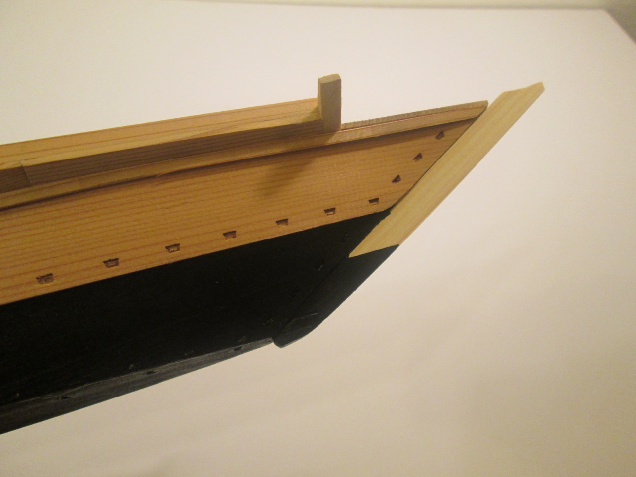
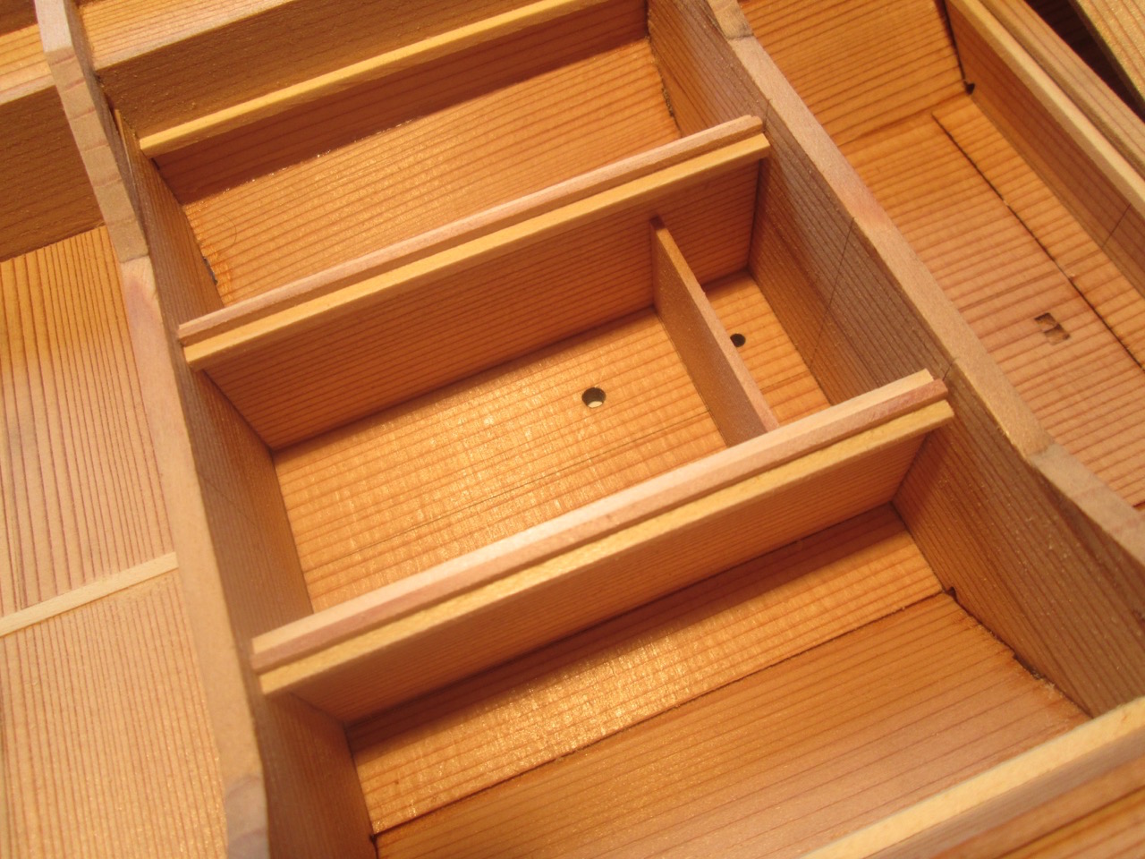
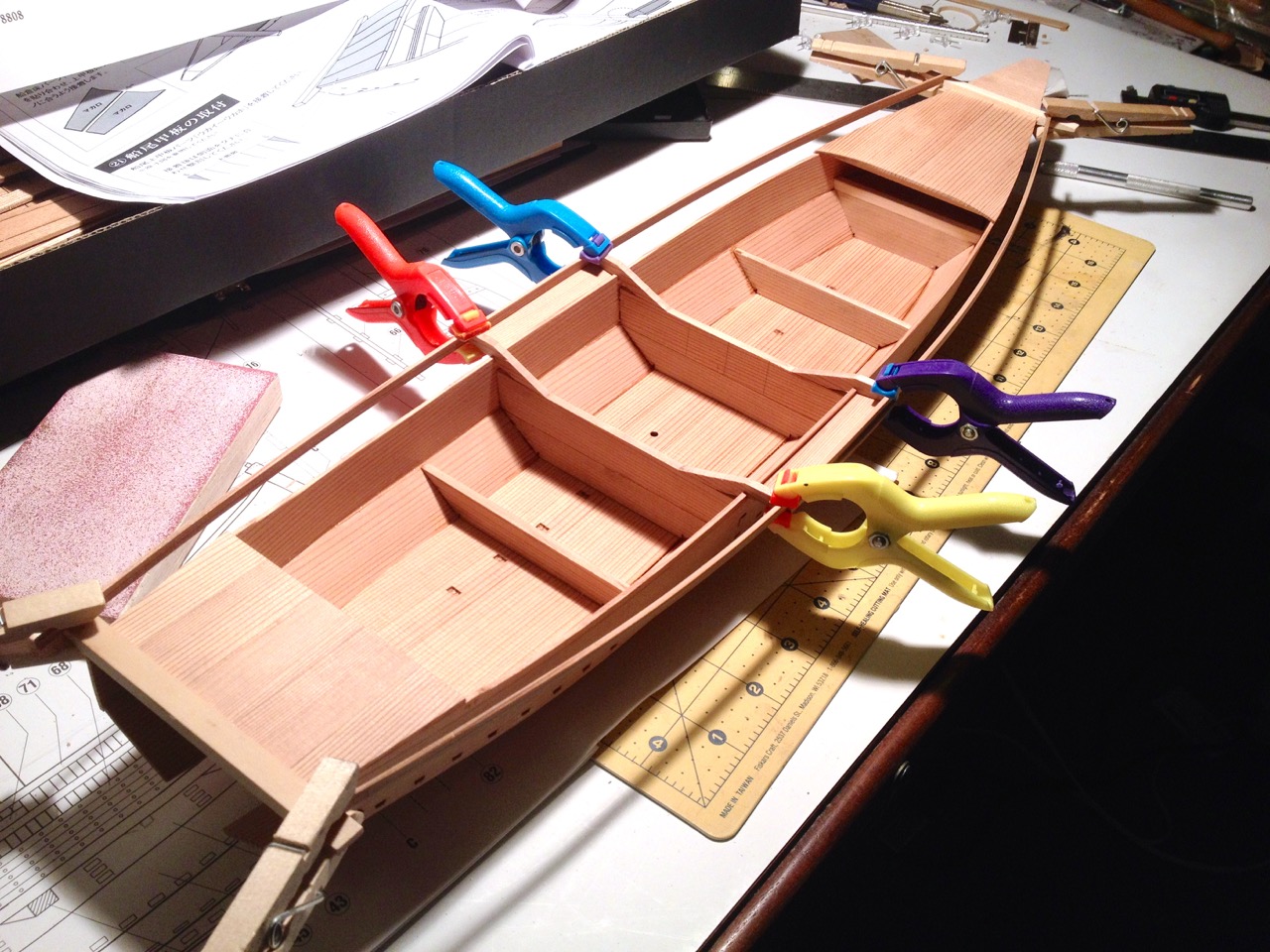
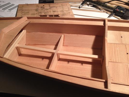
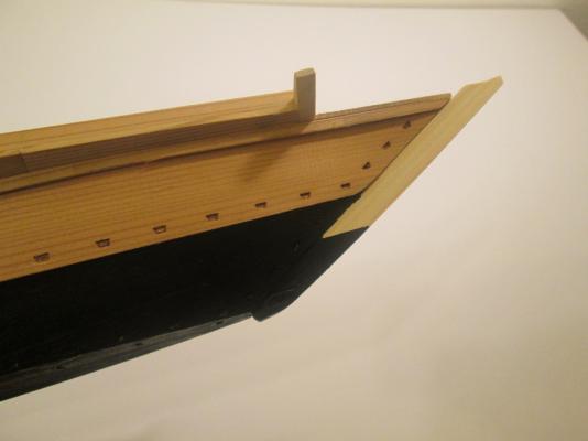
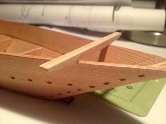
Thanks, Druxey. Always good to know you're out there! Sam, looking forward to it whenever you're able to get to it. Hope everyone has had a nice Christmas. For me, it was a short break, and now back to work and projects! I recently made contact with the manufacturer and sent him some links to my blog and MSW posts. Next thing I know, someone from the Tosa Traditional Japanese Boat Society reached out to me and also there is a post on Facebook. Here's a link to their Facebook page: https://www.facebook.com/tosawasen/?pnref=story I tried to link to the actual post, but I don't see an easy way of doing that. But, in any case, I found the guy who actually drew up the plans for manufacture, Toshihiko Shibafuji. He studied traditional Japanese boatbuilding with a master boatbuilder, Mr. Hiromitsu, and it also turns out he knows Douglas Brooks, who I already know. So, it seems that the circle is complete! As for the model, it was time to paint the bottom of the hull. The finish of the hull bottoms changed a bit over time. But, what we see as common for the Edo period would be black paint. While I was at it, I went ahead and added the splash rail. The joint where the two piece meet and also the bottoms of the pieces had to be beveled to fit properly. Here's another view... Finally, I built the well area. This was pretty straightforward, though I did start to run into little discrepancies in part alignment, which is going to happen on kits with pre-cut parts. Also, a reminder that it's REALLY easy to over sand the kit's Japanese cedar. The bottom of the boat will be comprised of covered compartments. So, beams and ledges will be added to seat the deck boards / compartment covers. The well section is the tallest compartment. Here, I'm adjusting the position of the ledge that I'm gluing into place on one of the well partitions. I used wood from the sheet of deck covers as a guide for exact positioning of the ledge. This assures that the deck covers will be flush with the tops of the partitions. Here's the completed well area before deck covers and fitted into place. Note the ledges glued to the hull. Clare

- 51 replies
-
- 10
-
-
- wasen
- thermal studio
- (and 1 more)
-
Hello Sam, There is only one book on Japanese boat building that I know of that's written in English. It was just published last Fall. If you can afford the full price, you can get it from the author's website douglasbrooksboatbuilding.com. All profits go to support his research. He was one of the speakers at the NRG conference in Mystic this year. Both the Hacchoro and Yakatabune kits are about the same level of difficulty, a bit less tricky than the Tosa Wasen, and you don't need to know anything about Japanese boat construction to build them. But, it's nice to know about traditional construction so you can see how the kits have simplified the process for the modeler. The Hacchoro makes a nice display because it's big, has tall sails and eight sculling oars and the kit's not too expensive. As always, I recommend getting them from Zootoyz.jp. His prices are generally better than what you find on Amazon, his service is great, and if you use EMS shipping, which I recommend, you should have the kit in about a week or so. The Tosa Wasen, I bought off of Amazon-Japan and had to use an intermediary since there were no international shipping options. I'm checking with the manufacturer about options though. It's easier to find images of Hacchoro on the Internet because they still have modern built replicas and hold regular Hacchoro races in Yaizu city, I think it is. But, it helps to do your image searching using Kanji characters and not type out Hacchoro in English, or you'll just get nothing but links to my own blog site! So, just copy and paste this: 八丁櫓 I'm planning on building another Hacchoro in the not too distant future. Whatever you get, I hope to see you start a build log on one here! Clare
- 51 replies
-
- 4
-
-
- wasen
- thermal studio
- (and 1 more)
-
Thanks for the nice comments all. Regarding the difficulty of the kit. In general, it's not a difficult build as there is no rigging, few fittings, and lots of laser cut parts. Beams, stem pieces, and other wooden parts are pre-milled as well. No long pieces of strip wood that need to be cut to down, no sheet wood or dowels. Even so, I wouldn't go so far as to say it makes a good beginner's kit. First off, the instructions are all in Japanese. Secondly, it's made using traditional materials used in the real boats. Cedar is a little splintery, strong grain makes it difficult to cut straight when trimming, and it's a little soft and easy to over sand. It seems to make a nice kit for someone who has some experience and wants a different kind of challenge. Probably best to have some interest in traditional Japanese boat construction. Otherwise, one of the Woody Joe kits like the Hacchoro or Yakatabune might be a better option. Clare
- 51 replies
-
- 5
-
-
- wasen
- thermal studio
- (and 1 more)
-
Hi Burnside, that's one NICE looking model. Great job you've been doing. Very inspiring build. Clare
-
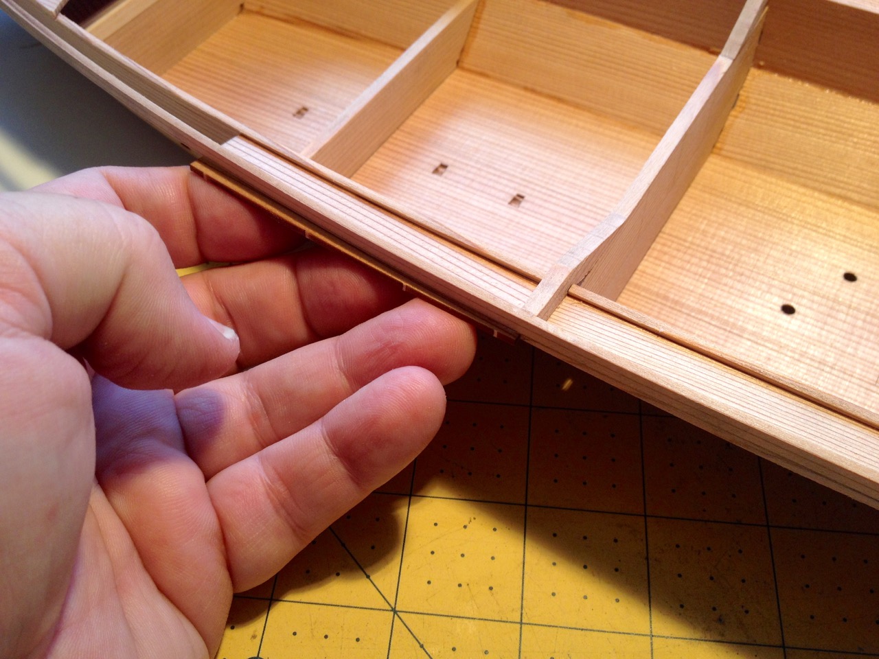
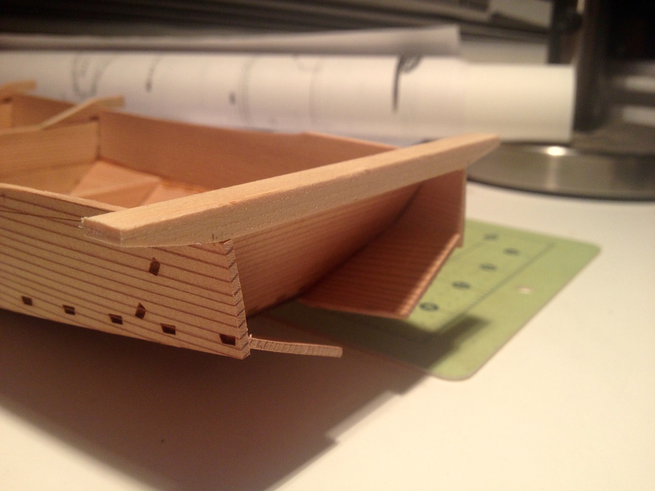
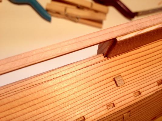
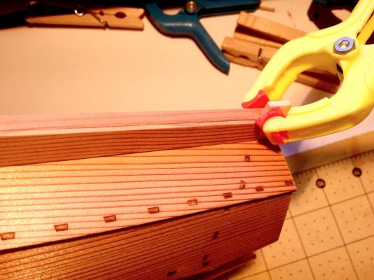
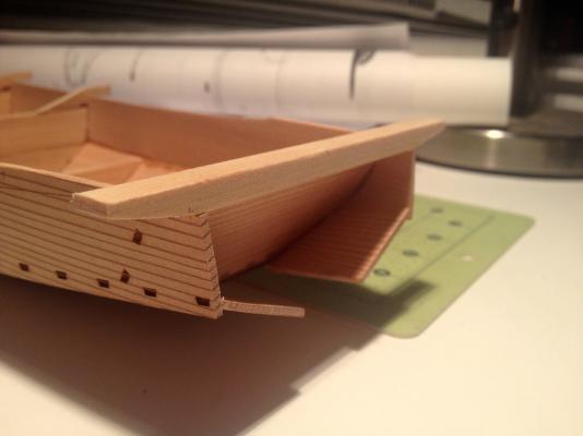
I continue to make progress on the model, but there isn't really much to say. I completed construction of the rail, adding the pieces that make up the underside. With these in place, it's a much stronger structure. To fit the pieces into place, I had to soak the cedar pieces a little bit to impart a slight bend or twist here and there. I took the shortcut of wrapping the pieces with a wet paper towel and put them in the microwave for about 30 seconds. This was just enough to do the trick. Along the underside of the rail on the upper hull planks there is a laser-scribed line to help position the underside pieces of the rail. The pieces glued and clamped into place After the rail was completed, I went ahead and added the stem and other hull details include a thick strake located on the upper hull planking, just underneath the recently completed rail. You may notice that the stem is lighter than the rest of the hull. Like the stern beam, the stem is make of Hinoki or Japanese Cypress instead of Sugi, Japanese Cedar.


- 51 replies
-
- 13
-
-
- wasen
- thermal studio
- (and 1 more)
-
Hi Bob, You're inspiring me to get to work on my second Higaki Kaisen model. After finishing my first one, I received another as a gift. Also, I managed to acquire one of the larger Kitamaebune kits, which are out of production, as well as a Sengokubune kit. Their larger size is better for display purposes, but these aren't as detailed as the Higaki Kaisen kit and, I think, not as accurate. So, for now, they're just in the standby stack! Looks like you're getting close to the home stretch here. Have you thought about making a ship's boat to go with it? Don Dressel made one for his model. I thought about it, but never got around to figuring out how to make one. I figured I'd eventually add one on top of the forward deck house, but nothing yet. Anyway, your work looks terrific, and the finish is superb. Looking forward to seeing you and your model at the NRG conference next year! Clare
- 196 replies
-
- 4
-
-
- higaki kaisen
- woody joe
- (and 1 more)
-
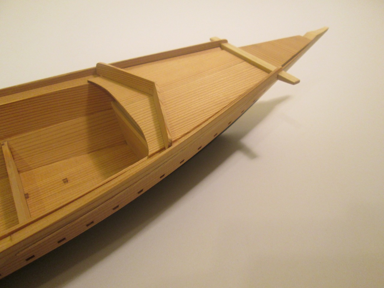
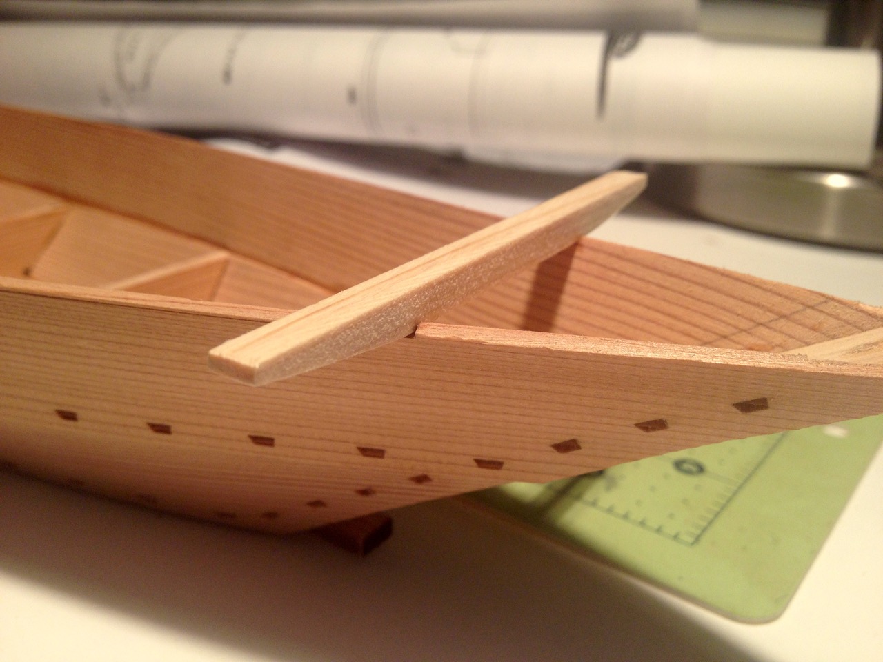
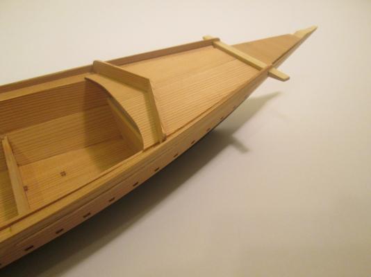
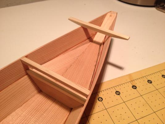
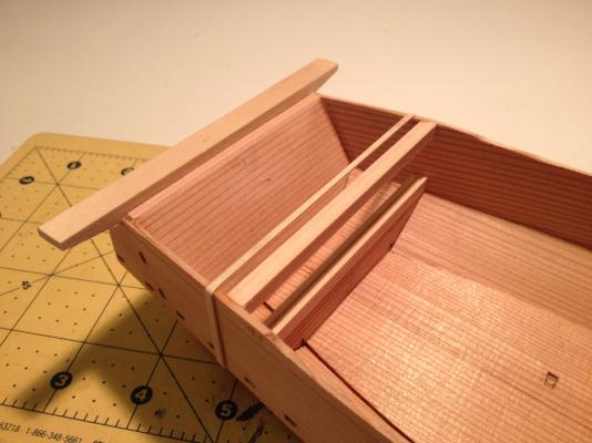
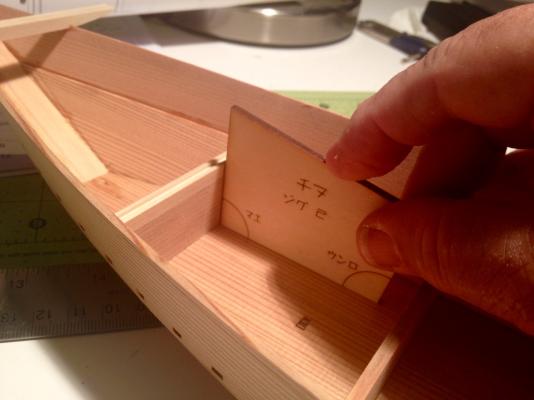
Thanks Richard, Bob, John. Welcome Antony – No worries, there's plenty of project left... I got stalled for a bit when I got to the rails, but managed to complete the bow and stern decking. The bow deck first required installation of support beams. The beams are provided pre-cut, but the ends needed to be tapered to fit snugly against the hull planking. The deck itself is made up of two pre-cut pieces of cedar. The stern deck is made up of 5 pre-cut boards, but the pieces are of different widths. The instructions don't show you, but the plans provide the labels, so you can locate the needed pieces. You don't have to read Japanese, but you do have to match the characters on the plans with those on the parts. To those familiar with Japanese, the labels are all in the phonetic alphabet known as Katakana. In this case, the parts are: ウカイ ウカロ ウカハ ウカニ ウカホ These characters don't actually mean anything, they're basically no different than labeling parts as A1, C2, etc. Most of the parts in the kit are identified this way. Something else to note is that the pieces aren't necessarily placed on the sheets in any order. Efficiency of material was very obviously given precedence here, so related parts may be separated quite a bit. You can see this by how these deck pieces are located on the laser-cut sheet. The deck parts are glued up and I then placed them on the hull and traced the edge onto them using a pencil. This was then trimmed by knife and sanded to fit the hull. One thing you'll notice is that the part labels are etched onto each part, so you have to either hide the labels or sand them off. Or, you could always just ignore them. They're not that easy to see unless you're looking closely. In this case, I just glued the boards so that the labels will all be on the underside of the deck. Now, here's where I was at a bit of a loss. There are rails that attach to either side of the boat. The ends are notched to fit to the beams at the bow and stern, but the pieces are too long to fit. So, the notch at one end can be used, but the other end has to be cut to deepen the notch. More than this, where on a western style ship, we're accustomed to installing framing and then attaching the rail onto that, with Japanese boats, the process is reversed. The rail is installed to existing attachment points first, then the supports are added afterwards. This is something that I've seen in hull construction of Japanese boats too. The hull planks are edge fastened and bent/clamped into place in the process, and the framing is installed afterwards – Lessons in traditional Japanese boatbuilding! Of course, this isn't limited to the Japanese or Asian ship/boat building. Thinking back, I recall local ship modeler and marine archaeologist Ed Von der Porten talk about modeling a Basque whale and about how frames were added after the planking process had begun. Anyway, I finally worked it out in my head, and the rail construction is in progress. I should have the rail completed soon, but I think it's been the hardest part of the build so far. More later... Clare


- 51 replies
-
- 10
-
-
- wasen
- thermal studio
- (and 1 more)
-
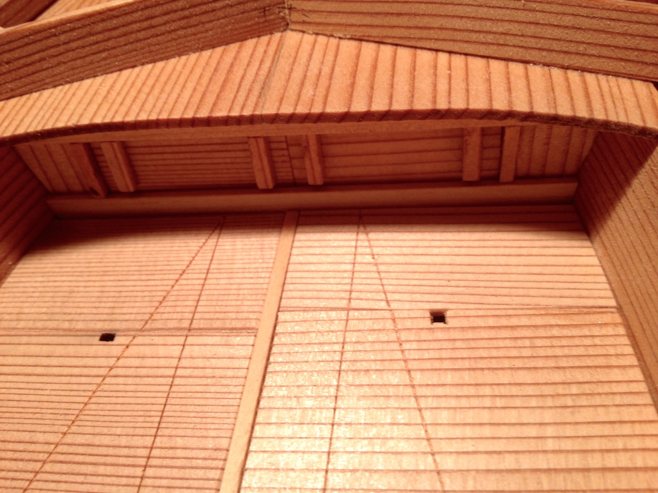
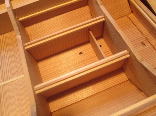
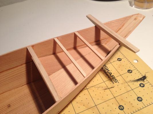
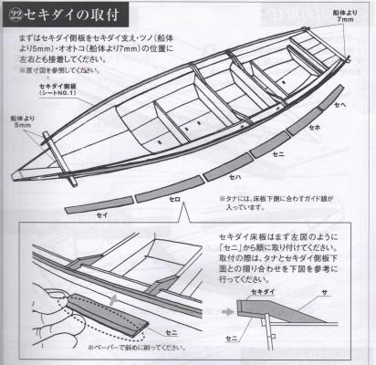
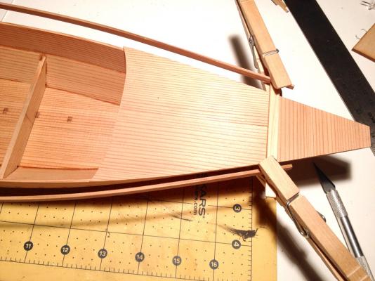
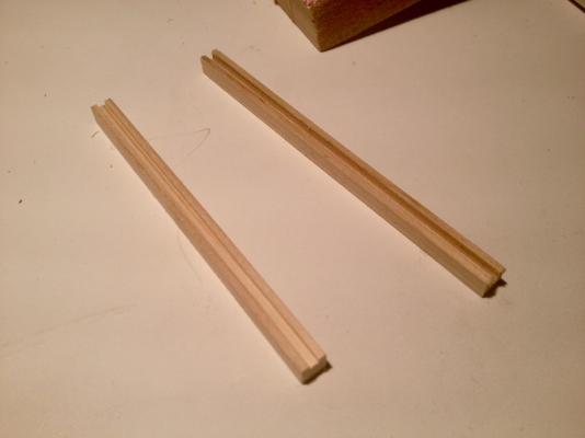
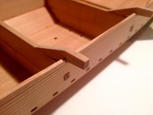
Hello Druxey, thanks for the comments. Always nice to have you following my builds! Last time, I left off with the basic hull completed. Now comes the detailing. A pair of beams are provide which are attached directly on top of the upper hull planks. These are first tapered from underneath so that at the ends they are reduced to half thickness. The fore beam referred to here as the ツノ or Tsuno (tsue-no), and the stern beam is the オオトコ or Otoko (oh-toe-koh). The heavy stern beam in particular is a common feature of traditional Japanese boats as it is used to mount the rudder on some boats, and usually bears the seat for the sculling oar. One thing you might note about these beams is that the parts are made from a lighter colored wood. True to the original boat, unlike the hull planks, which were made of Japanese Cedar, these parts were usually made out of Hinoki (Japanese Cypress) because its greater density and strength. At this time, there are some extension pieces located at the midships frames (I was calling them beam initially, but now they're built-up high enough to call them frames or bulkheads). I don't know what it's called yet, but this boat has an extended rail outside of the hull and these pieces are the central supports for it. These small pieces initially had a lot of char from the laser cutting on top and bottom. I was as careful as I could be to not take off too much material. But, the cedar is relatively soft and it sands a little too easily here. But, I seemed to manage okay and essentially got the char off. By the way, something interesting about that space between the frames that you see in the photo. In the center portion of the hull bottom, there are a few holes. I believe that this might have served as some kind of "live well" that must fill with water through those holes. There are in fact, two sets of holes. Near the forward bulkhead, there are two smaller holes in the bottom, and I believe these open into a smaller, separate section that might have been for storing bait. I'll report on this at another time after i've collected some facts. So, next step was to add the upper and lower slotted beams, which will hold removable doors to allow access into the bow and stern storage compartments. The ends of the beams had to be sanded down to fit nicely in place. A special template is provided to make sure that the beams are properly aligned. One side of the template is used for the bow and the other side is used for the stern. The angles are different enough so that it's pretty obvious which side is used for which end of the boat. You don't need to read Japanese to figure that much out. One of the issues I ran into was that the tops of the upper hull planks weren't perfectly aligned. So, I made an extra effort to make sure the gap between the upper and lower beams was consistent. After the stern pieces were done, I assembled the floor of the bow storage compartment. Interestingly enough, the two pieces that make up the floor aren't two symmetrical halves. In fact the joint between the two doesn't even run parallel to the centerline of the ship. You can see what I mean when you look at the photo. I'll cover the completion of the holds next time. The next step is to add the deck beams to the bow compartment and then the add the bow and stern decks. Clare
- 51 replies
-
- 8
-
-
- wasen
- thermal studio
- (and 1 more)
-
Thanks John, this is a really looking kit, and as long as I don't screw up the steps, it should turn out very nice! With the lower planks in place, there are next two support beams that were glued in place. Like the pair of lower support beams that the lower planks lock into, these upper support beams are notched so that they fit into holes in the upper planks. When the glue on those beams was drying, the upper planks were cleaned up the leading edges were tapered the same way as the lower planks. The lower planks were then glued to the support beams described above. As with the lower planks, the upper planks were then initially glued only at the transom and at the stem. Fitting the planks was fairly easy at the stern, but was a bit harder at the bow. There, the planks are hard to seat tightly against the stem since there is some overlap between the upper and lower planks. This definitely took a lot of hand pressure and the use of medium CA glue since I couldn't get a clamp onto the bow. I just had to hold the planks tight as long as possible until the glue set. At the stern, the planks were much easier to glue. But, I did run into one self-created problem that was actually less of a problem than I'd realized. The stern edge of the transom should have been lined up with the edge of the notch where you see the rubber bands in the above photo. I cheated a little in order to fix the problem by trimming the leading edge of the notch, effectively moving the notch forward. A beam is supposed to fit precisely into this notch, so I had to sand the stern edge of the planks just enough so the size of that notch was retained. But, as it turns out, the top of the transom gets sanded flush with the top of the planks and later the whole section gets covered with planks right up agains that beam anyway, so you wouldn't have been able to tell that the transom didn't touch the edge of the beam, unless you looked up at it from underneath the boat. With the planks secured in place, I then ran a thin bead of CA glue all along the inside of the joint between the upper and lower planks. Lots of clamps made sure that the planks were held properly together until the glue set. After a while, it was safe to then remove the temporary strong-back, which was a nice and satisfying milestone in the build. With that, the basic hull is complete and we have something that now looks like a boat. There is still the outer stem to add as well as some stern trim that protects the ends of the planks, but aside from that, it's pretty much time to start detailing. Clare
- 51 replies
-
- 10
-
-
- wasen
- thermal studio
- (and 1 more)
-
Welcome, there's plenty of room for all! I don't expect we'll be here all that long. Though it's not a simplified construction model, the design is not complicated. The next stage of the build is the hull planking. On a traditional Japanese boat, there are basically only 4 planks, 2 on each side, with the upper planks making a nearly vertical surface. The kit refers to the lower planks as カジキ or Kajiki and the upper planks as タナ or Tana. The term Kajiki is the same term used for the lower planking on the Bekabune as described in Brooks' book and blog. And in fact, the Tosa term for the upper plank, Tana, is related to that of the Bekabune, which is the compound word Uwa-Tana, but run together the "T" becomes a "D" sound and becomes Uwadana. Diagrams in the kit show that the leading edge of the lower planks need to be tapered. There are measurements shown in the instructions, but the exactly shape of the tapered area is not precisely defined. It ended up being a matter of getting something to look like the shape shown in the diagram – a shape that reminds me of the tip of a samurai sword. After tapering the leading edge of the planks, it's then a matter of fitting the planks on. The laser-cut planks have square openings that line up with square tabs that protrude from the central beams on the model. These are actually located slightly aft of center, but they are at the widest point of the boat. I found that mating the planks to those notches was a pretty tight fit, but it was good that the fit was snug, as this helps hold things together while gluing. I glued the planks to these notched frames first and let that dry, which seems to be how the instructions want you to do it. Next, the planks were fit to the transom and glued only at the transom. From what I could tell, it seemed that the top of the planks should be kept low against the frames, so that the planks ended up sticking up above the frames by only a small amount at the stern. On the forward half of the boat, the planks seemed to mostly line up with the top of the frames. The planks were then glued to the stem, which is called the Miyoshi (mee-yoh-shee). The planks had to be positioned so that the very forward edges were flush with or just barely past the stem. After the glue dried, the rest of the planking was glued to the bottom and the frames using medium CA and the applicator tips supplied in the kit. Those, by the way, were a perfect fit for ZAP brand glue bottles. I found it a bit of a struggle to hold the boat while trying to glue the lower planks into place. The strong-back in the center is only glued in at the top and bottom of the transom and the stem, so it's very flexy. It took a while to learn to hold the whole thing while bending the planks and gluing them into place. I should also mention that the kit never has you soak any of the planking. It's long and thin enough that it flexes pretty easily. I suppose it might have made sense, as a ship modeler, to try to pre-bend the planks. But, it certainly wasn't necessary and I managed without soaking or pre-bending the planks. I left the whole thing to dry and then came back and sanded the upper edges of the lower planks. When dealing with the upper planks, the will overlap the edges of the lower planks, and to make a good bonding surface, or watertight surface in the case of the real boat, the outer edge at the top of the lower plank has to be sanded roughly vertical. On the real boat, iron nails would be drive into the bottom edge of the upper plank and into this flat edge of the lower plank. Of course, there's more to it than that, but that's the basic idea. At this stage, the model is just about ready to receive the upper planks or the Uwadana. Clare
- 51 replies
-
- 12
-
-
- wasen
- thermal studio
- (and 1 more)
-
Hi Grant, Ken, Carl, Bob welcome! Hope you enjoy the build. It's been an exciting start. I saw one of the blogs on the build of this kit maybe about a year ago, but couldn't find the kit anywhere. When I found one in a listing in Japan, I snatched it up, hesitating only to make sure it would actually get to me one way or another. I've been in contact with boat builder Douglas Brooks for about 2 years now and, following his work, I've been wanting to try scratch building a boat he refers to as a Bekabune, a seaweed harvesting boat from Tokyo Bay. It is relatively simple and small, but I didn't want to fully commit to it yet because I felt there were just too many questions in my head about the building methods. With him the only source of information, I didn't want to be bugging him all the time. I think the Tosa Wasen model project will help me through some of those building issues. I'm getting a sense of the difference between the two boats, what kinds of things might have been simplified in the kit design, construction techniques, etc. I don't expect this to be a long project – I'm already on step 8 of 41. But, I do have a rigging repair I'm finishing up at the same time and then some. Plus, I'm translating each step to make sure I'm not missing anything major, and that takes time. Still, though I'm in no rush, I'm betting I'll be done by New Year. Clare
- 51 replies
-
- 5
-
-
- wasen
- thermal studio
- (and 1 more)
-
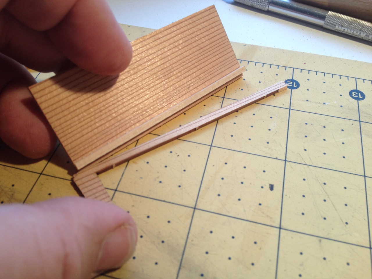
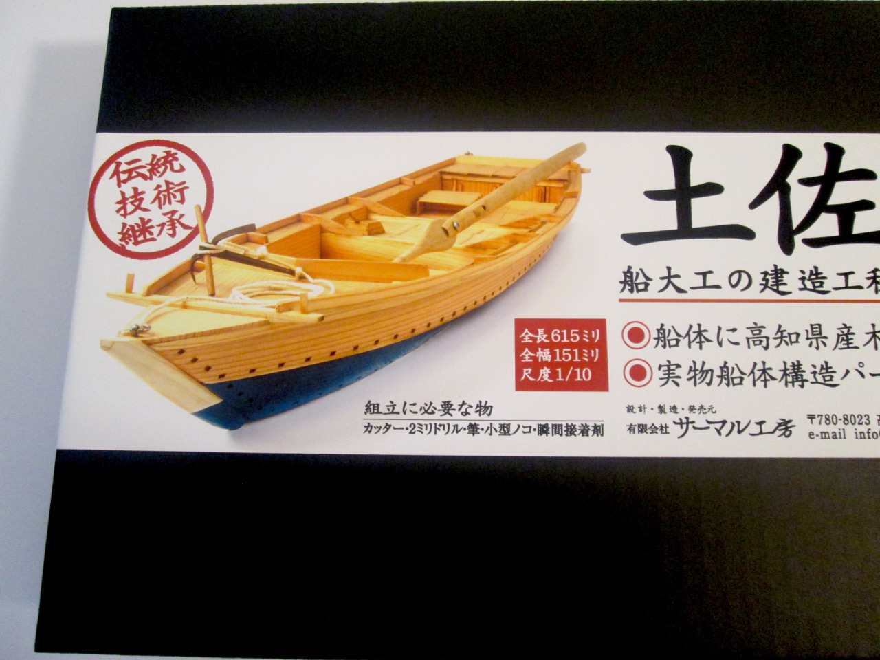
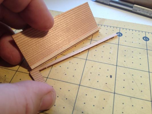
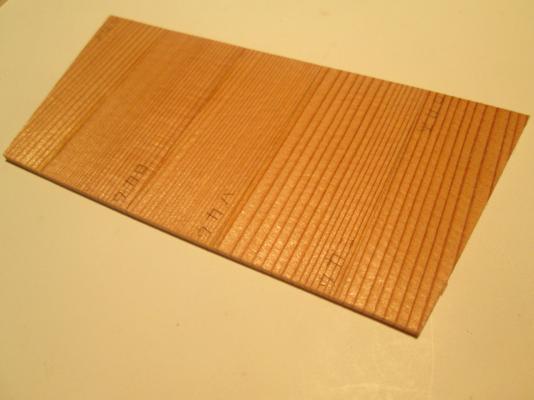
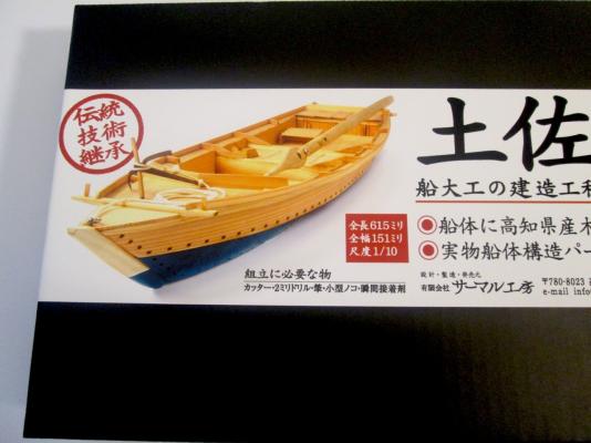
I purchased this kit from a dealer in Japan, having found it on the Internet some time ago. This is a very accurate model of a traditional fishing boat from a region called Tosa on Shikoku Island, which is one of more Southern of the 4 main islands of Japan. The kit was produced by a company called Thermal Studio, which is actually a manufacturer of glider kits. I suspect that there is some personal connection between the owner and the Tosa Traditional Boat Society. The manufacturer indicates that this kit is made under the supervision of that group. I won't go into too many general kit details, since I already discussed the details of the kit on Model Ship World here: http://modelshipworld.com/index.php/topic/12018-110-scale-japanese-fishing-boat-kit-from-thermal-studios/ The build begins with the floor piece. There are apparently different regional names for this and I don't know what the name is in the Tosa region. The term カワラ, or Kawara, is shown a lot for it in the instructions, so I assume that's the regional term in Tosa. I'll have to send an inquiry about these things at some point. The first step in the kit is to bevel the bottom edge of the kawara. To aid in this, there are laser scribed lines. Interestingly enough, the sheet with this part is actually scribed on both sides. I've never seen that in a model kit. This means that the manufacturer had to register the wood and the laser in some way so that the cuts on one side line up with those on the other side. Something interesting about working with the Japanese cedar. Where those dark lines in the grain show, that's where the wood is more dense. When carving, you have to be aware of that because those lines are harder to cut through than the lighter colored wood in between. These dark lines are also harder for the laser to cut through. So, if you look in those etched trapezoidal holes, you can see lines of wood that line up perfectly with the grain. I started to trim out those ridges in the cut-outs. There aren't that many really, so I'll probably continue with that as I go. The other issue with those lines is that they can make the laser scribed lines very hard to follow. Woody Joe uses laser scribing to mark the beveling lines on their kits too, but they use light color Hinoki, so I 've never had to deal with hard to see scribed lines before. The next thing is to partially cut through the Kawara at the dashed line. This is where the bottom of the boat angles upwards. In his book Japanese Wooden Boatbuilding, Douglas Brooks describes this as Kirimage (kee-ree-mah-gay), or "cut bending". I don't know about the Tosa boats, but the Aomori boat he worked on used a technique like this, though there's more to it. In my case, I thought this was a good opportunity to bring out my Japanese hobby saw, which is a very thin pull-type saw. The problem was that it was too thin. It cut nicely, but didn't leave room for the piece to bend upward. So, I pulled out my old razor saw and I cut the line several times, holding the blade at different angles, so that it would cut more of a V-groove. With that done, I could add the floor frames. These are permanent frames, thought a long strong-back piece serves as a temporary alignment guide. This was interesting because so many Japanese boats are frameless, or close to it. At some point I'll look into this further. On the real boat, these may have been added after the planks were in place. There was a fair amount of char on the edges of these and all the other wood pieces. The kit includes a large flat sanding block that made clean-up of these parts pretty easy. I did notice that there was a fair amount of smudging on the wood faces though. I cleaned these up as best I could. I used the sanding block, but tried to keep working very lightly. I test fit the stem to how it was all going to work. The stem is made up of an inner piece and an outer one. The outer stem gets added later, but the inner one goes on next. I wanted to make sure I understood the design before continuing. First, I had to made sure the strong-back was properly aligned. The main issue was to keep it centered and perpendicular to the Kawara. The piece is also to be spot glued at the very ends to keep it in place until it is removed in a later step. Here's where I'm at now. Steps 1 through 6 have been completed. I have only to bevel the stern most frame and the transom to complete step 7, then comes the lower planking. Japanese boats use very wide planks that are often very thick. On the Tosa wasen, the planks appear to be as much at 18" wide. I went ahead and started prepping the lower planks. Where I am cutting in the photo, the laser does not completely cut the dark lines of the wood, so I have to go over this with the X-Acto a few times on each side to cut the pieces free. Clare
- 51 replies
-
- 15
-
-
- wasen
- thermal studio
- (and 1 more)
-
1/10-scale Japanese Fishing Boat kit from Thermal Studios
catopower replied to catopower's topic in Wood ship model kits
Actually, it makes more sense for me to review the kit here so it's not mixed in with the build itself. The kit is not all that heavy, about 1-1/2 pounds, but it's in a long box. I think this kicked the shipping cost up a bit, which was just about $30. Still, a ship model kit, particularly one this rare, for around $170 total, is not bad. That's just about what I paid for the Woody Joe Hacchoro and the Yakatabune kits I bought from Zootoyz. Having ordered through Amazon Japan, the only seller of the kit did not ship internationally, so I had it sent to someone that then re-shipped it for me from Japan and they didn't charge me any service fees. He's done this twice for me and I don't want to impose on him any further. There are companies specifically set up to forward packages from Japan. I just finished setting up an account with one called Tenso.com. Next time, I'll try them out. By the way, it looks like I may have been wrong about this kit being out of production. I thought it was no longer manufactured because the company that makes it, Thermal Studios, primarily makes large model glider kits and doesn't list the Tosa Wasen kit at all. However, I emailed them about it and if we understood each other correctly, they produce the kit. Perhaps it's more of a local item since they are apparently close to Tosa, Japan, and seem to have some kind of connection with the Tosa Traditional Boat Society. The kit itself is basically made up entirely of several laser cut sheets, plus a small bag with various kinds of parts, some other separate laser cut and milled wooden parts, instruction booklet, plan sheet, and even a sanding block. The laser cut sheets are made from Sugi (that's "Sue" plus "Gee" with a hard "G") or Japanese cedar, just like the real Tosa boats. Sugi is aromatic, though not as strong scented as Hinoki used in so many Woody Joe kits. The parts are laser etched with Japanese characters to identify them. This makes locating parts a little more time consuming than if they were numbered. But, I guess it's just a matter of pattern matching. The bag of parts contains all the milled wood parts, all short pieces. Also in the parts bag is the metal anchor, the anchor rope, metal rings and fastener. The kit also includes a roll of yellow hobby masking tape, and for some reason, some plastic applicator tips used for applying CA glue. As expected, the instruction booklet is all in Japanese. The black and white printed book is 26 pages long and includes a parts diagram on the back cover, showing all the laser cut parts on their sheets. The diagram is pretty small and you really need a magnifying glass to read it. But, magnified, the part identifiers all appear to be readable. Instructions are divided up into 41 steps, with each step being clearly illustrated and each looking to be pretty simple steps. Time will tell if the Japanese text printed in the booklet is really necessary or if the model can be build solely by the drawings. But, in addition to the booklet, there is also on large plan sheet that gives a nice overview of the boat at full scale, which, by the way, is 1/10 scale. Overall, this looks like a really nice kit and it's not that expensive. An additional bonus is that the manufacturer, Thermal Studios, created a blog showing photos of the construction steps. This is really nice because it reinforces the written/printed instructions, giving you another view of the steps. Also, using Bing or Google translators, you can view the blog pages in English (or whatever your native language). This isn't always that great, as the translation can be pretty questionable, but it often helps. Thermal Studio's Building a Wasen Blog Having attended Douglas Brooks' talk at the NRG conference this past October, and having been reading through his book on Japanese Wooden Boatbuilding, I can say that this kit looks very authentic and true to the way that the traditional Japanese shipwrights would have actually constructed their boats. This kit would make an ideal study project for someone who is interested in following the work described in Mr. Brooks' book. Personally, I've been planning on scratch building the Urayasu Bekabune that he discussesin his book. I think that building this kit first will help me a long ways towards understanding Japanese boatbuilding so that I can eventually attempt that scratch project. Clare- 25 replies
-
- 11
-