HOLIDAY DONATION DRIVE - SUPPORT MSW - DO YOUR PART TO KEEP THIS GREAT FORUM GOING! (89 donations so far out of 49,000 members - C'mon guys!)
×

catopower
-
Posts
1,897 -
Joined
-
Last visited
Content Type
Profiles
Forums
Gallery
Events
Everything posted by catopower
-
 In addition to asking Chuck to do a one-off laser cutting job, I understand Bluejacket also provides the service. I've used Pololu, one of the companies that Chuck mentions. You can use the material they supply, or you can send them the material you want to use. Not sure which services will do the necessary CAD work for you, but Pololu accepted an Adobe Illustrator file to do my laser cutting work.
 -
Thanks Druxey, Carl. Bill, working from copies is smart. I have done that at times, but I get lazy with it and end up using copies as my backup. The color on the printed parts is so good that I don't even bother copying those. If I screw up, I'd probably just pick up another kit. Coming from the wooden ship modeling background, and knowing the amount of time spent on model making, the cost for the kit is pretty insignificant. As for the Cleopatra kit, I'm inclined to agree with Chris, and would avoid buying from Chinese sources right now. As far as I know, all the Shipyard kits are of the same A3 format, so 8" x 11" doesn't sound right. You can always email Shipyard and see if they can tell you. But, none of the Shipyard kits I have are bound into a book. All the sheets, including the cover and back cover are separate. HMS Victory is the only Shipyard kit that I've personally seen that is in a staple-bound book format. Also, GPM has the Shipyard HMS Cleopatra kit and a laser-cut detail set for it (gpm.pl). If you ordered the laser-cut detail set, you'd be able to tell right away if your kit is the right scale or not. Also, the kit itself is less than $25. Clare ***Follow-up*** I just looked at one of the Shipyard lighthouse kits, and it measures 8-1/4" x 11-5/8". If that's what your kit measures, then maybe it's okay.
-
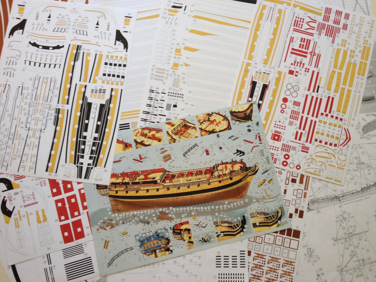
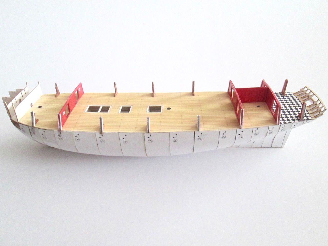
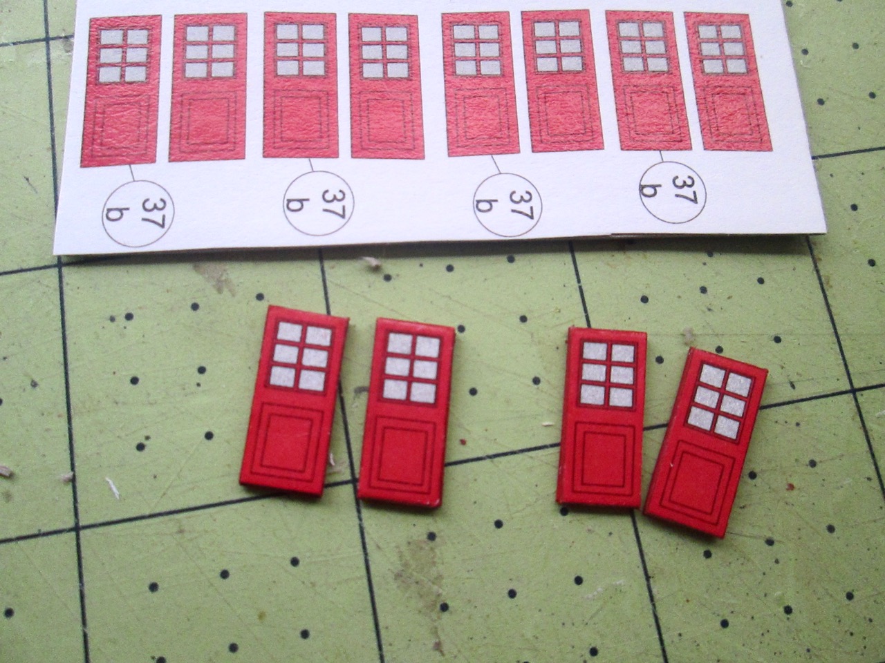
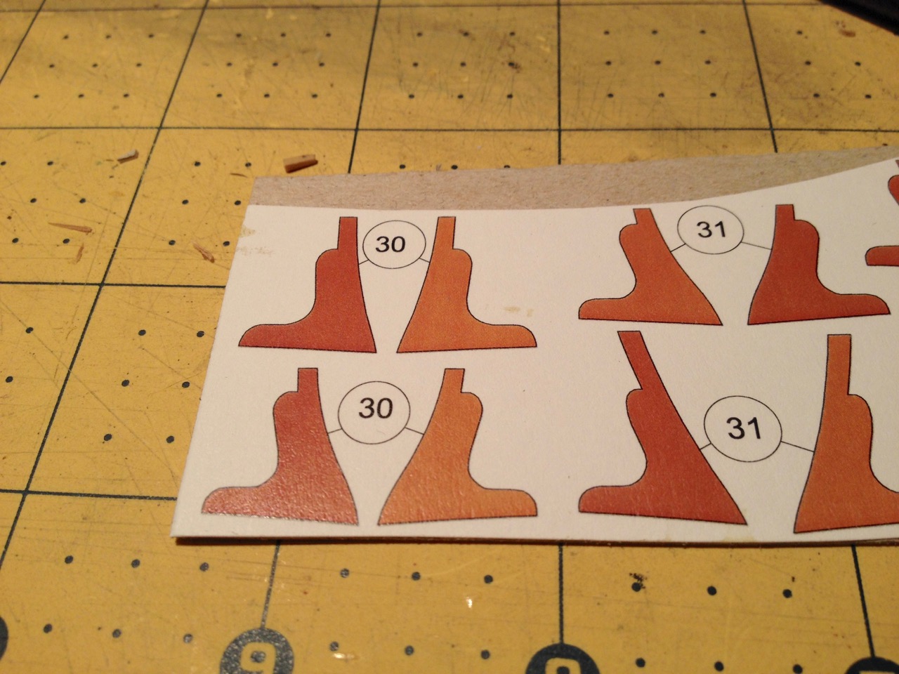
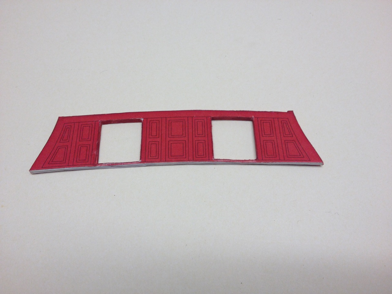
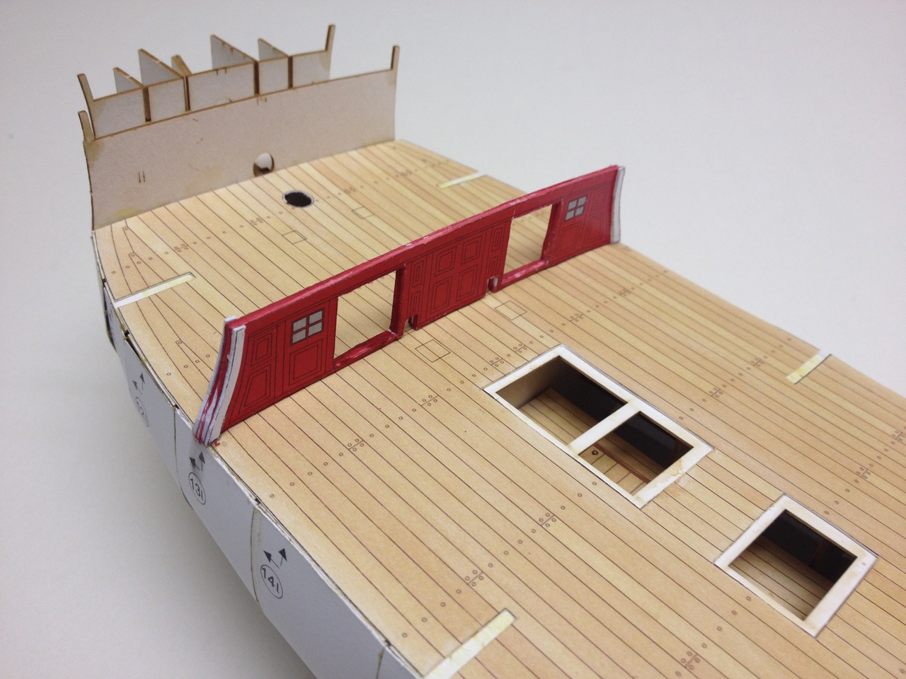
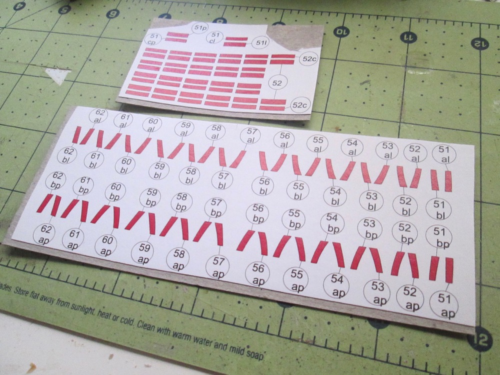
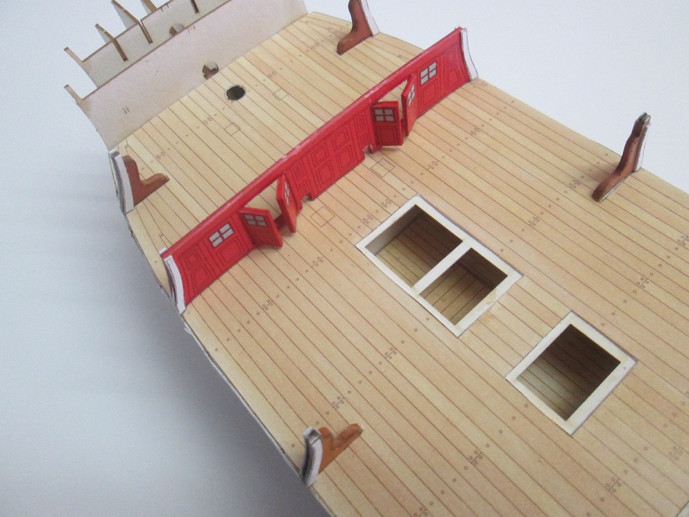
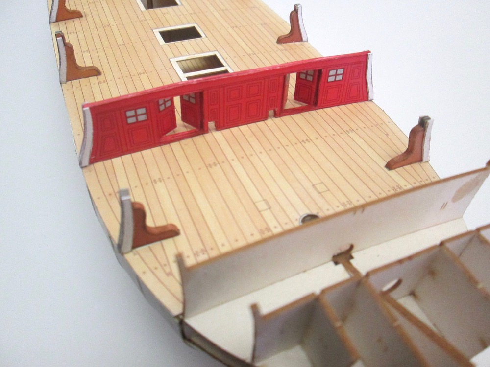
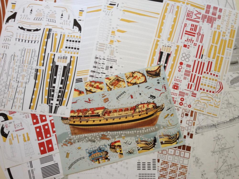
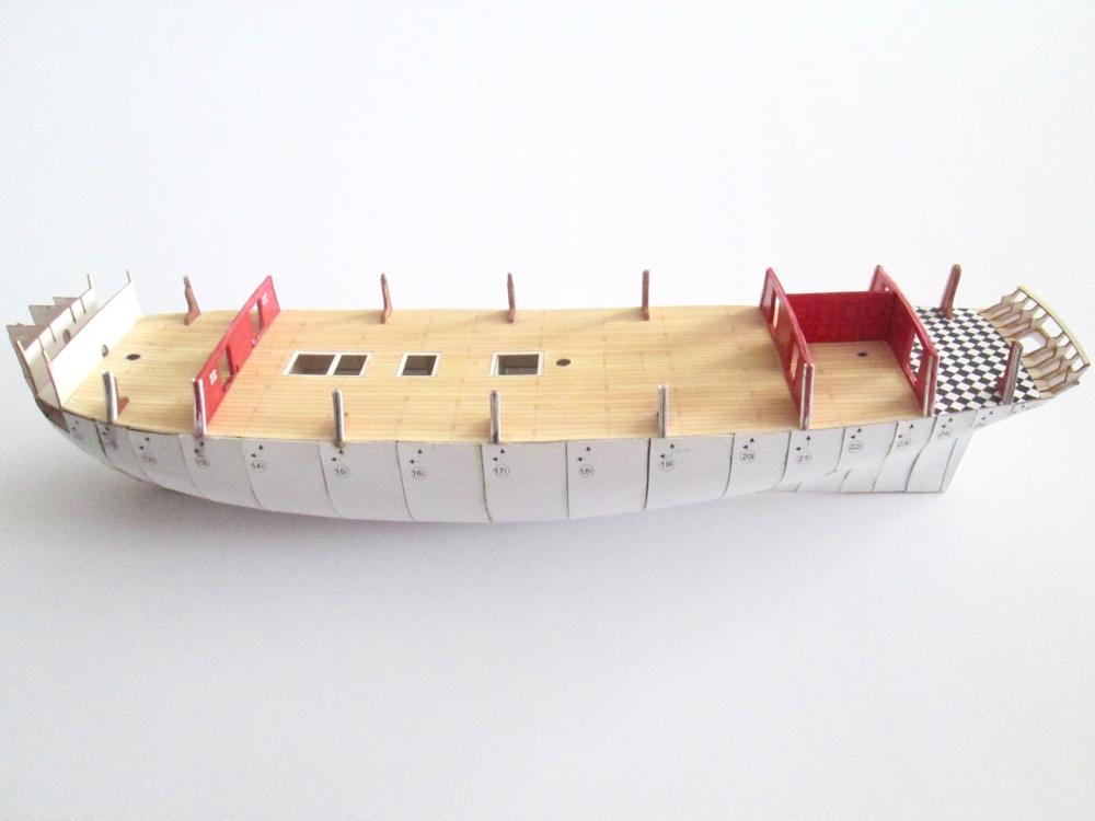
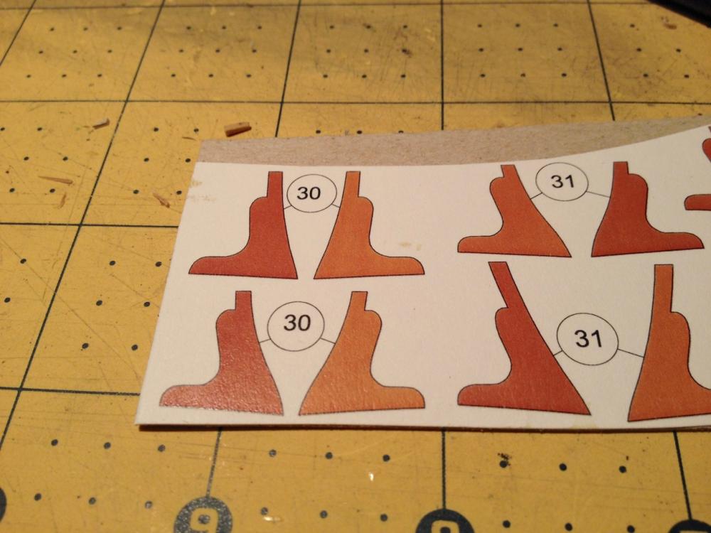
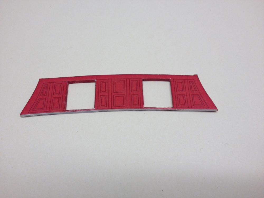
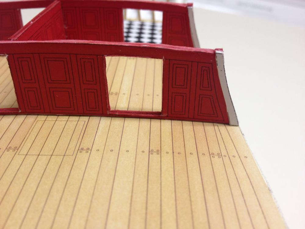
This SHOULD be my last update for a little while as I've got some other things I need to get back to. HMS Mercury has been a great part-time distraction and it's terribly addicting to work on. I'll TRY to set it aside for the next couple weeks as I get some other project work done and prepare for a trip to Japan I'm making at the beginning of next month. More on that later/elsewhere. Well, I managed to put all the interior partition doors in place. For the most part, since these are separate parts, I left them in some degree of openness. This lets light shine through, which is useful, since the internal windows are just printed. As I mentioned before, the gallery lights are also just printed, but the separate "detail set" from GPM has laser cut window frames, so the gallery lights should look a lot more natural. I was all set to start making the gun port frames, which are constructed from 4 pieces each. Then, I discovered that I'd lucked out and don't have to cut out all those parts because the detail set has them already cut. There'll be plenty of tiny parts to cut later. For now, it's nice to avoid that step. Here are the kit's printed parts, ready to cut... Here are the detail set parts, already laser-cut, shown here painted, ready to remove from the sheet and glue up... What you may note here though, is that the gun port frame pieces are individually numbered, because there is a slight difference between them. The detail set isn't number like this, but the parts still differ. Fortunately, the parts are laid out on the sheet in the same order. But, you definitely have to keep the printed sheet intact to serve as a reference. Also, this makes it difficult to make all the gun port frames all at once. Best to make them one at a time and then attach them to the hull before losing track of which one is which. Clare

- 82 replies
-
- 15
-

-
Druxey, Thanks for the explanation! I don't have Shipyard's HMS Enterprize plans, which is the same class as HMS Mercury. I'd be curious to see if they included standards in those plans. They don't show up in their plans of HMS Success. Carl, You're right about those being faster to construct from wood. Once I get past the "paper" model project, it would be interesting to build multi-media style. Using materials that work or are easier to fashion, rather than trying to stick to a class of model. Still, I love wooden ship modeling, but working with another medium is quite liberating. I have Shipyard's Santa Leocadia "Super Modellar Plans", which includes the basic hull parts and some detail parts in paper. I pieced the laser-cut hull framing together as a demo display. Might be interesting to build that as such a model. We'll see. Long ways to go here. Back to my model... If someone out there works on one of these kits, and were I to do this again, I would consider taking and cutting a razor blade so that is very narrow and has a cutting edge maybe only 1/8" long or so. It might be possible then to chop out the printed window panes. Then, sandwich a piece of clear acrylic between the paper sheets for the windows. I'm beyond that stage now for these interior partitions and doors. For the gallery and quarter galleries, I have the Super Detail parts set from GPM. One of the nice things about the set is that it includes laser-cut gallery lights. So, I won't have to worry about those windows looking like silver colored paper. The set is about $24 at gpm.pl (Polish site) plus $12 shipping. It takes only a couple weeks to get, but you just have to put up with the fact that their address form isn't formatted quite right for US addresses. I kind of rearranged my address so it appears correctly. But, USPS seems to get it figured out okay regardless. The set also include laser-cut parts for the capstan, gun carriages, blocks and deadeyes, mast tops (I think), gratings (!), and figurehead. I don't remember what else. It's definitely worth the cost. I much prefer having these gratings on my model than the 2D printed paper. Clare
-
Gunther, I have a lot of kits in my closet too. But, I work on what intrigues me the most regardless of what's in storage. After all, I'll probably never get to all of those kits, and there's no rule that says I ever have to. I usually go through and cull them periodically, deciding which ones I don't really need after all. There's too much cool stuff out there. On scale, I know what you mean. I'd sworn off 1/8" scale at one time. But, I've come to accept smaller scales because of the sheer size of some models. I have a Victory in 1/78-scale in the works and it's big now, but when that bowsprit goes on, it's going to get crazy here. So, I've just put up with the small scale. Anyway, you can get away with faking more at smaller scales! Johnny, I'm looking forward to seeing those build logs. I need to see how this is done! Hey Chris, That's the beauty of paper models. How room do you really need to cut and glue paper? My wooden ship modeling work is all over the place. But, all the paper model work I can do in one small place. And, there's no "stuff" needed except glue, cutting mat and a few small hand tools. Well, of course, I understand your situation, so I don't slight you for not working on any paper models... much Bill, Do you have a build log for your Goeben? I'd love to see how the kit goes together. I bought the GPM kit of the Japanese pre-dreadnought battleship Shikishima. It's pretty interesting, but a very different kind of construction than these Shipyard sailing ship kits. Mike, These kits are amazing well engineered. It makes me wonder why these paper kits can have so many interior details, when a wooden kit has to be heavily modified just to be able to look through the gallery lights to see the inside of the great cabin. It does make me think that one of these days, some company is going to make a larger scale wooden ship model kit with lots of laser-cut parts in the fashion of these paper kits. Timmo, The Enterprize class is the one set of plans I don't have from Shipyard. I figured this HMS Mercury, being an Enterprize-class frigate would do. But, it would be interesting to try this in a larger scale. Don't get me started! Carl, You know, that remark about wood being considerably faster... If I didn't have so many other projects to finish, I might take that as a challenge. I'm beginning to think this model could go together very quickly. Clare
-
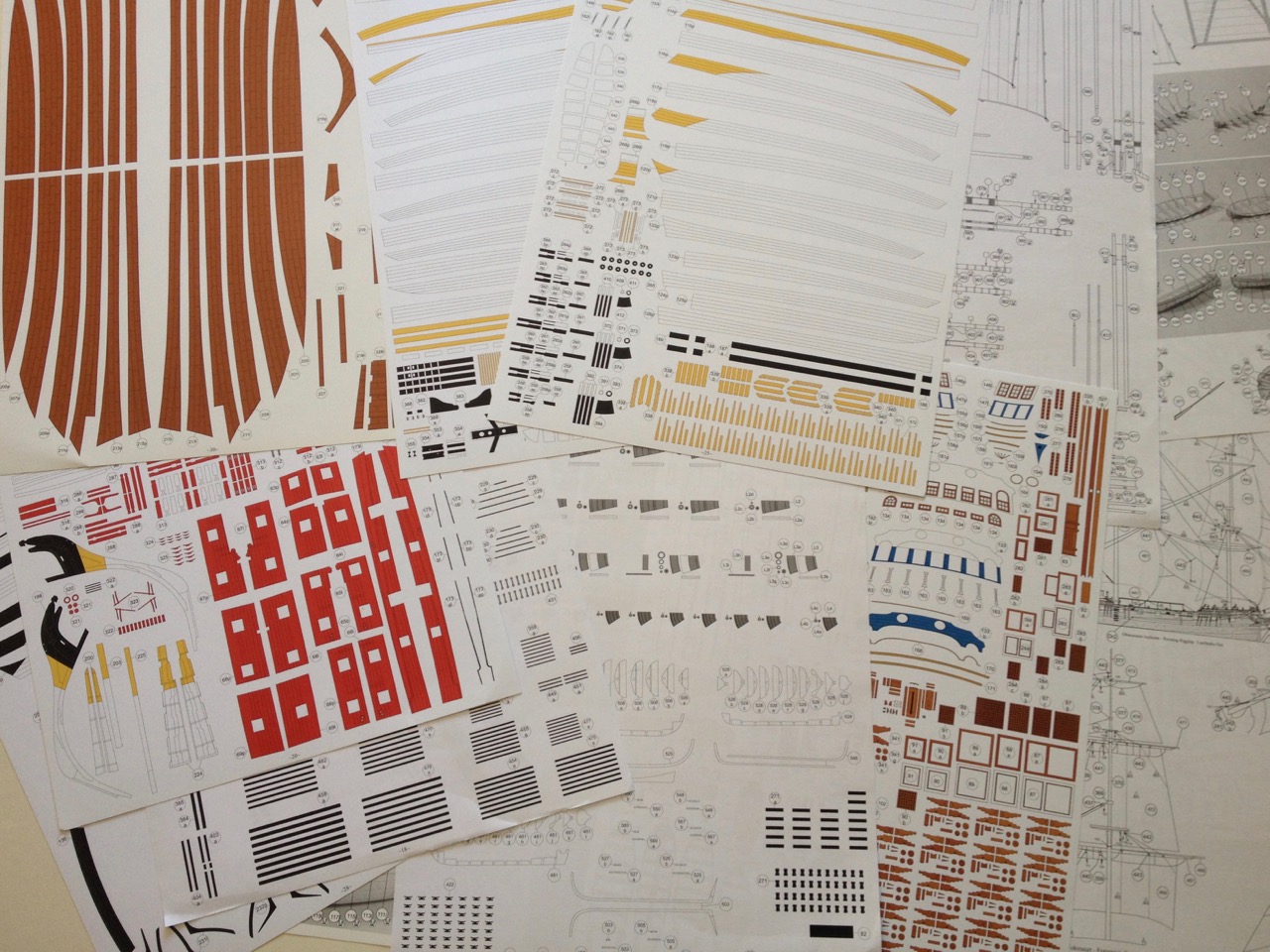
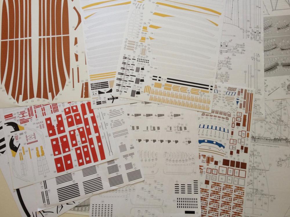
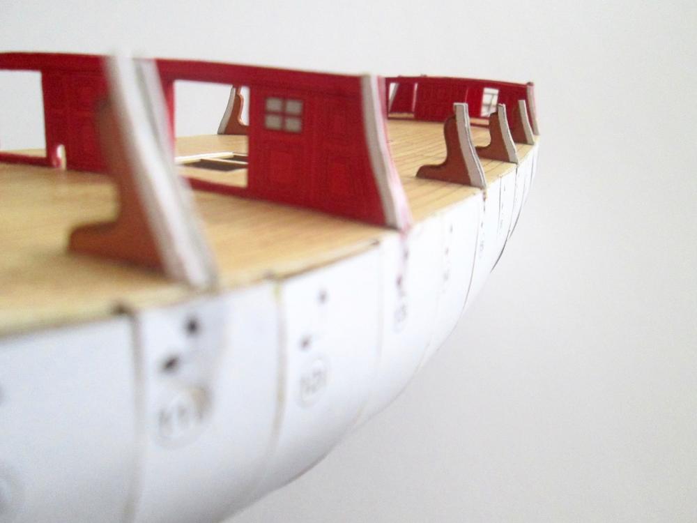
Thanks for all the replies! I really hope to see some more card model blogs soon. Makes for much better discussion when others are going through similar steps and card modeling issues. First off, for those who haven't seen the contents of a Shipyard paper model kit, here's a peek as what you get... Now, for a progress update. I've been putting in a lot of ship modeling hours, getting myself better organized and more productive – at least for now. HMS Mercury has benefitted quite a bit. For this most recent step, I've been constructing these inverted deck clamps. Strange addition, but most people won't know, and it's clear that they will support the bulwarks. Next up, I'm piecing together the interior doors and the gun port linings. I'll also cut out the bulwarks panels and figure out if I should glue the gunport linings to them before or after I put them on the model. I'm thinking, before. I haven't decided if I'll have all the doors in the open position or not. This is only my second paper model, so I'm still learning quite a bit. I think I'm wising up in my cutting and pasting techniques. Mostly, it's about the kinds of glue to use, the kinds of cardboard, whether to glue the printed pieces to the cardboard, then cut the whole thing out, or to cut parts while they're thinner and easier to manage, etc. One thing I've found was that while CA glue can really solidify a piece, the thinner stuff has a tendency to wick in the printed paper and cause discoloration. It's mostly noticeable on the printed deck. I'm going to have to do like I did with HMS Alert and give the deck another couple thin washes of slightly darker wood tone. That not only hides discoloration, but it takes the shine off of the printed paper parts and makes them look a bit more like wood. Clare

- 82 replies
-
- 17
-
-
Jonny, sorry I missed your post earlier about you building HMS Victory and HMS Wolf from card. Do you have a build log somewhere? If not, I hope you'll start one here on MSW. For one thing, I'd really like people to see that there are those of us who really are building models from paper (card), and they really are cool. Clare
-
Hi Chris, I just wish there was another card model build or two going on here. I'd love to see someone building one of the boxed laser cut kits. Ages of Sail has several. The 1/72 scale HMS Mercury kit is a bit too much money for me right now, but I would have considered starting the HMS Wolf kit if I didn't already have the 1/96 scale HMS Mercury paper model kit. Anybody out there thinking of starting one? Clare
-
Hi Carl, Yes, wood is definitely faster for some things. Then again, it's taken an incredibly short amount of time taken to get the hull to this point. But, cutting paper is a slow process when you have these inside curves to cut. For straight sided pieces or gentle curves, a pair of scissors is very quick! Clare
-
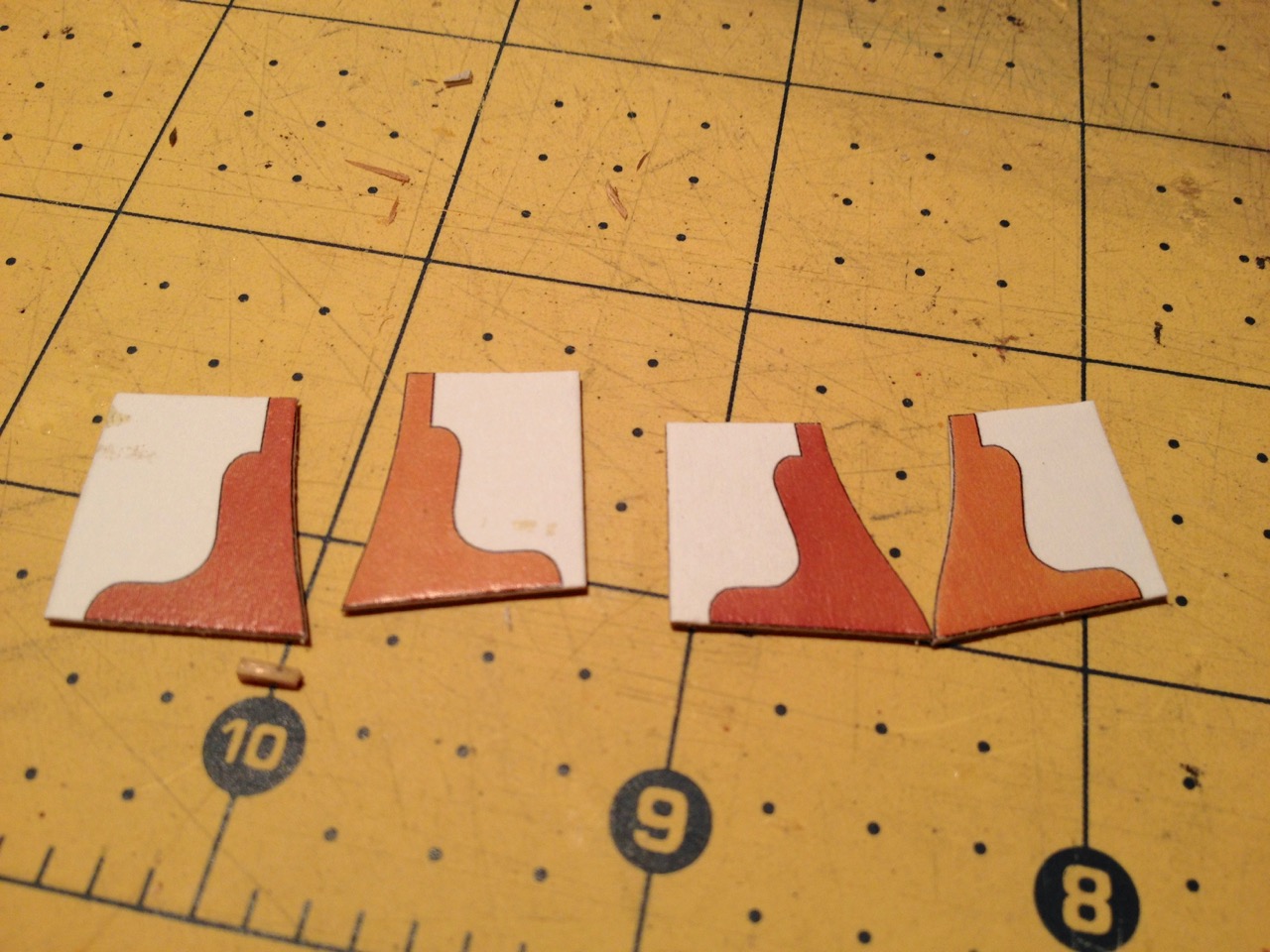
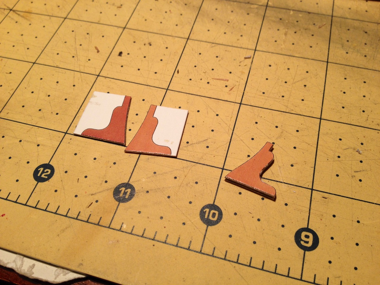
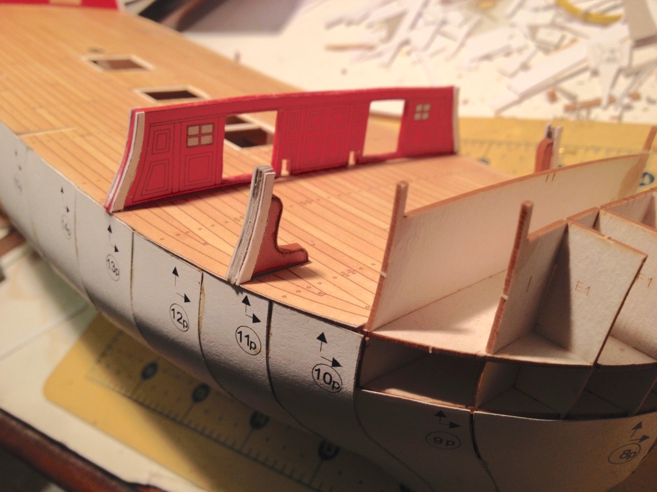
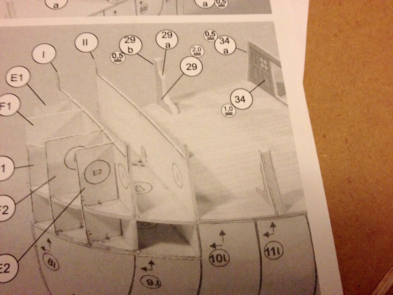
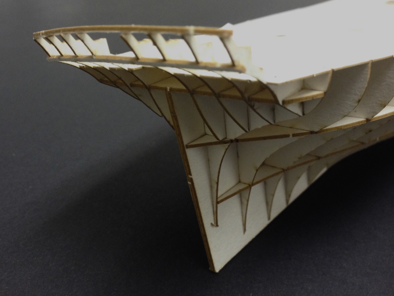
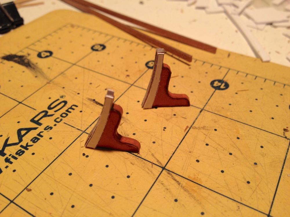
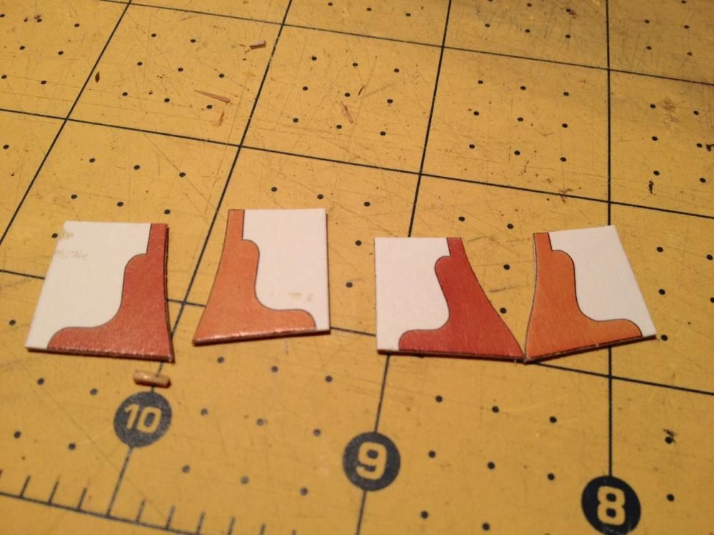
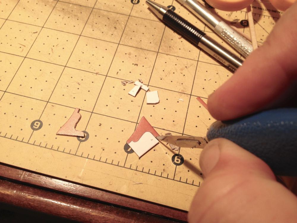
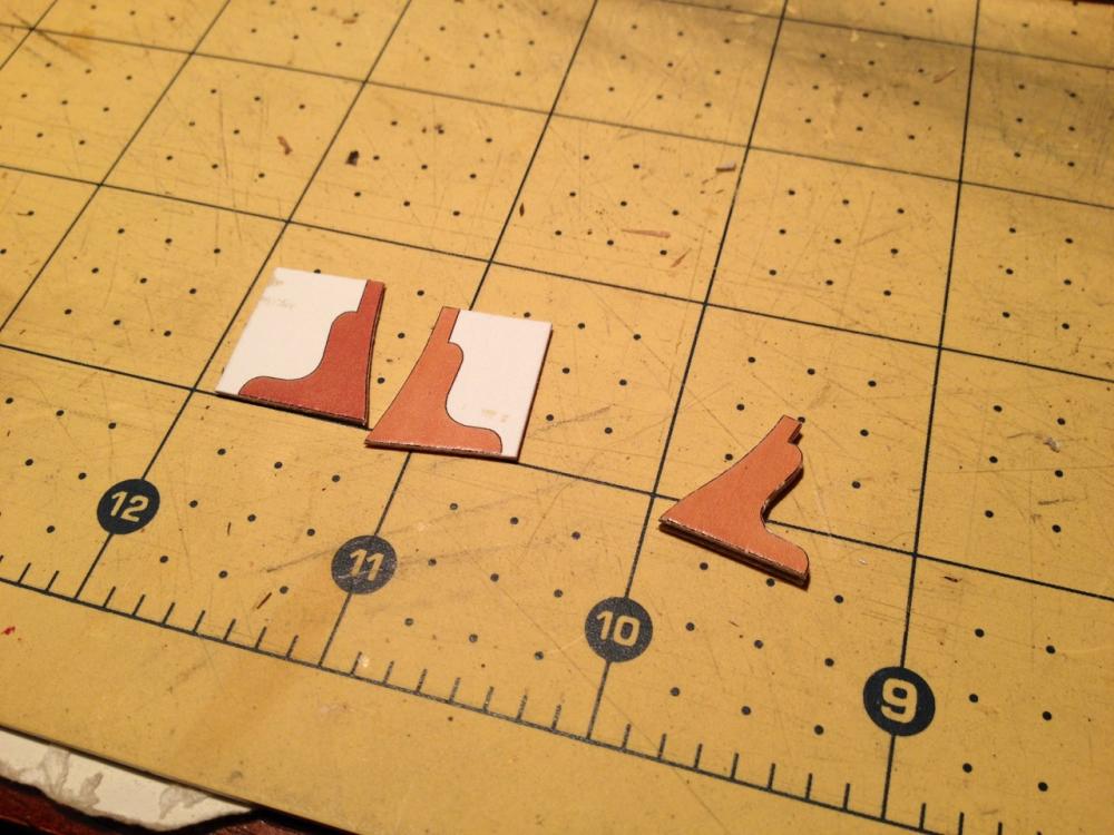
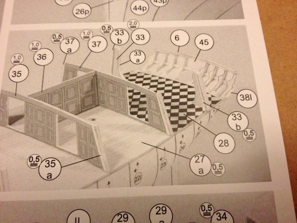
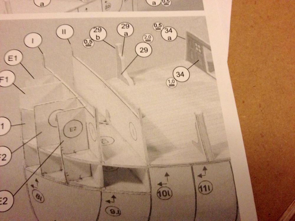
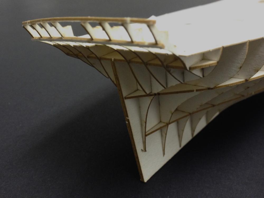
Welcome everyone! You'll have to be patient with this one in particular since it's very much a secondary project. But, I'll try to make periodic progress on it to keep it moving forward so you won't forget about it. Tonight, I sat down and worked on the bulkhead supports. These particular pieces look like inverted deck clamps and seem to be something of a model kit anomaly. The only references I could find that showed these a set of plans by the same company. Those plans are for the Spanish warship Santa Leocadia. Interestingly enough, I have another set of plans from the same company, but of another English frigate, and the plans show no such part. I am surmising that the part is the equivalent of bulkhead extensions in a wooden kit. They're needed to help shape the hull and to support the bulwarks planking, but they don't necessarily exist in real life. No matter. These are mostly hidden below the spar deck. I have to make several of these and it does take a bit of time. These are a little trickier than many other parts because of the inside curve that has to be carefully cut. Here's the process for building the part (similar process for all parts). The entire piece has to be about 2 mm thick. What I do is to then glue the main pieces onto card stock to make each half 1 mm thick. I use digital calipers regularly with paper model work. The first cuts I make using a scalpel or scissors. Note that an Xacto blade is really too thick for this work. A razor blade may be the best for cutting paper, but not entirely convenient. A scalpel is somewhere in between. Nice this is that you can buy a box of 100 blades, with blades coming individually packaged, for $5 with a basic handle. I bought a handle with a molded plastic grip on Amazon where I also bought the blades. Important thing with cutting paper with a knife, you need a cutting mat to work on, and you want to make multiple passes without trying to cut through in one pass. below, I made the initial cuts with a pair of sharp scissors along the easy, relatively straight lines. The inner curves require more careful work. Tight turns require multiple short cuts. One thing that is useful is, after glueing the two pieces together, wick some thin CA into the cardboard. That will make it work like plastic and you can sand that inside curve smooth with a piece of rolled sandpaper. Finally, some spacer pieces are built-up, cut and added. The completed pieces glued into place on the deck. One thing that is very confusing is that there is a difference between the port and starboard side pieces, yet the parts all have the same part number, and there is no indication that I can find to explain which side the longer piece goes on. In fact, all of these bulkhead supports are the same way. You can see what I'm talking about in the second photo above. Finally, I thought I'd include a couple photos to show what the instructions look like. One pair down, another 4 pairs to go... Clare

- 82 replies
-
- 19
-
-
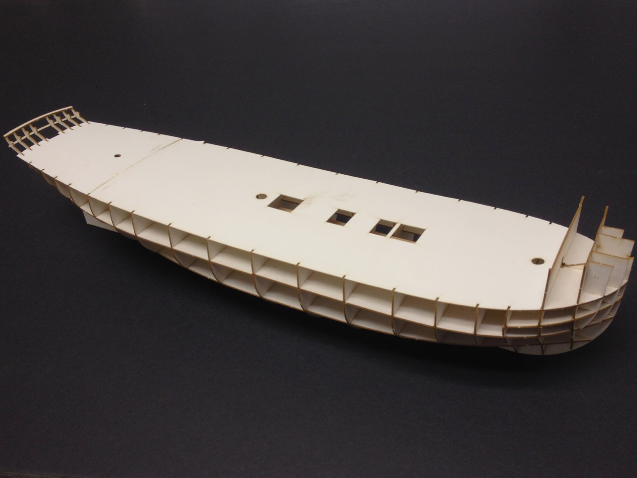
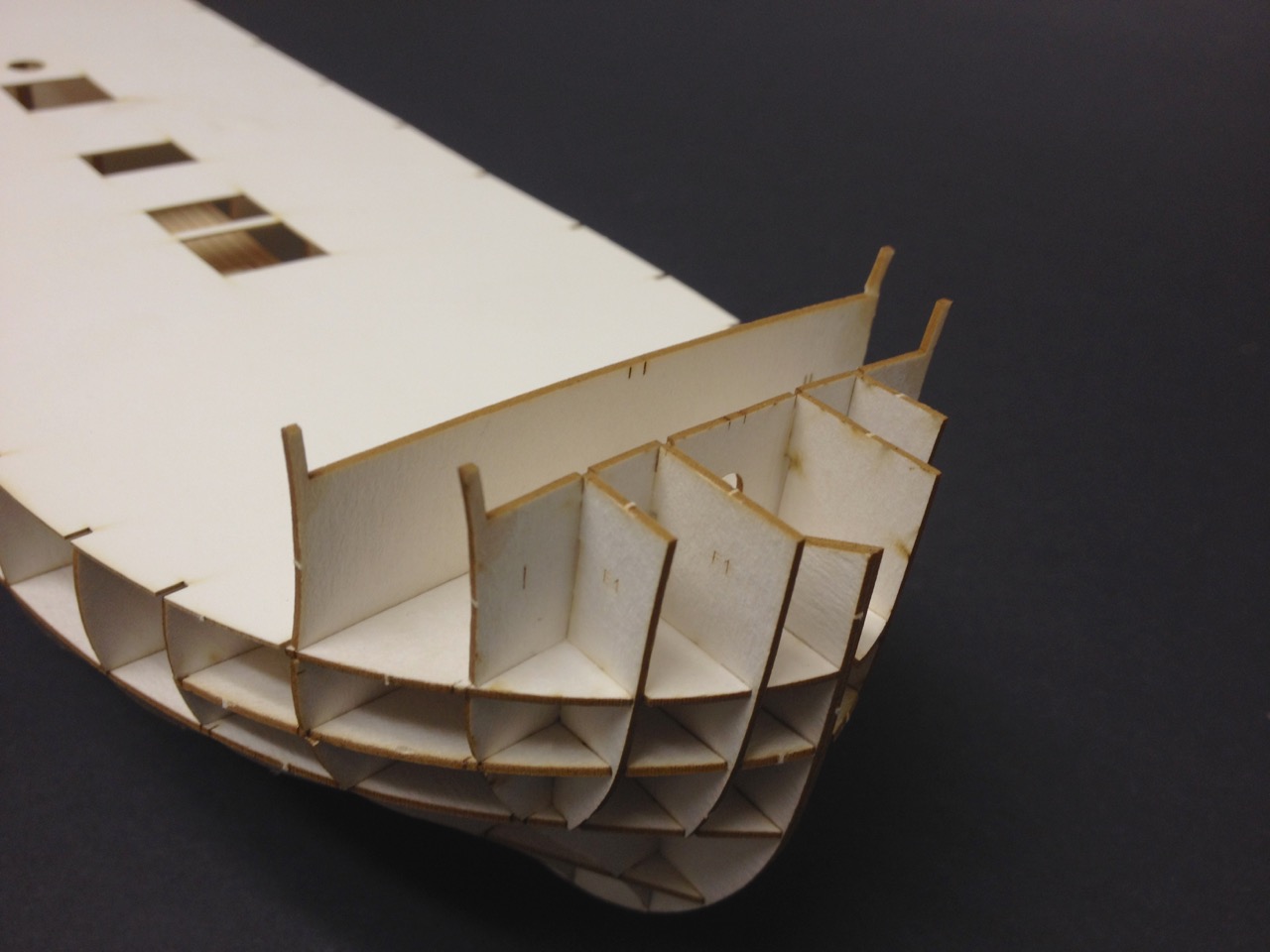
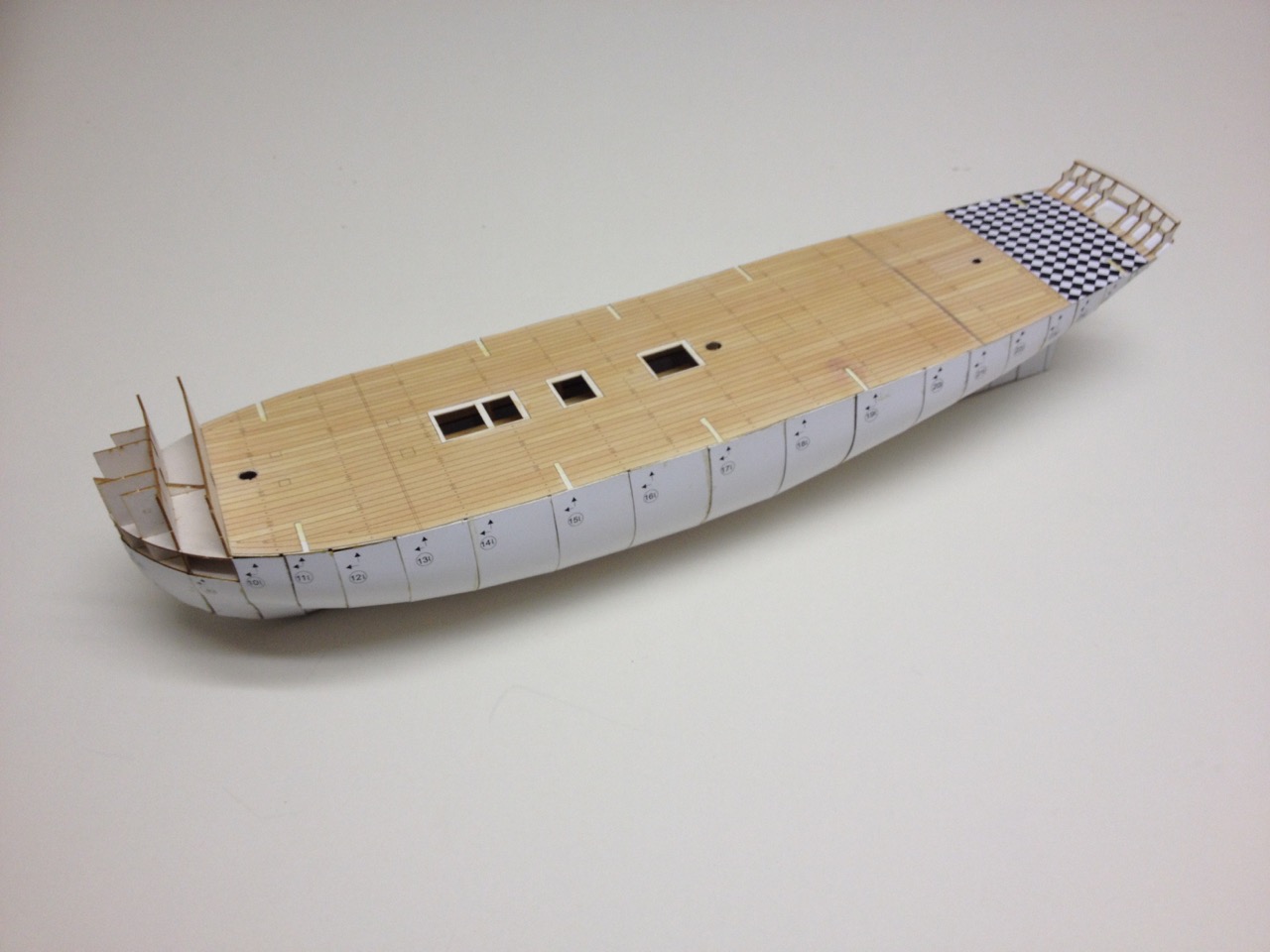
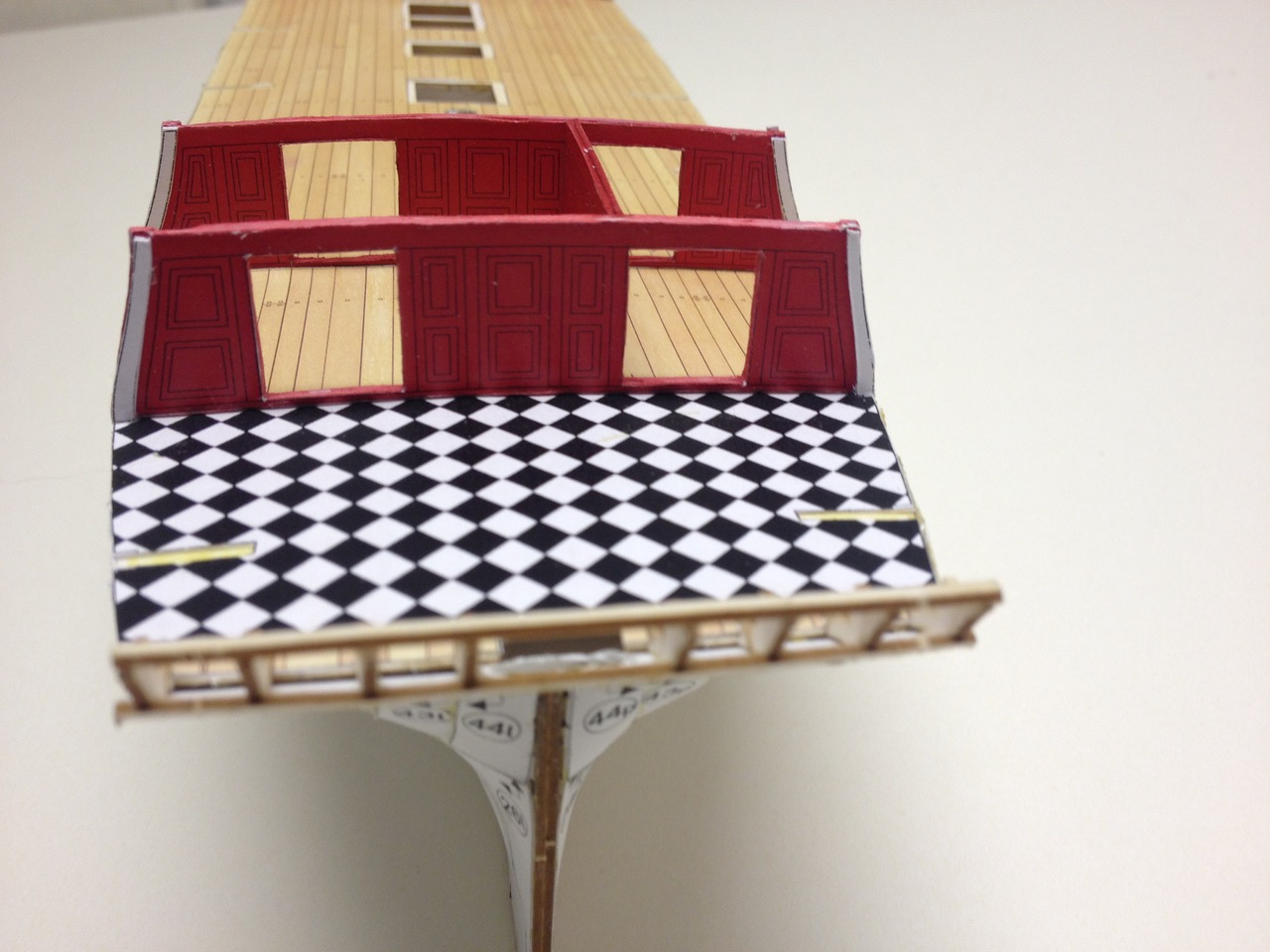
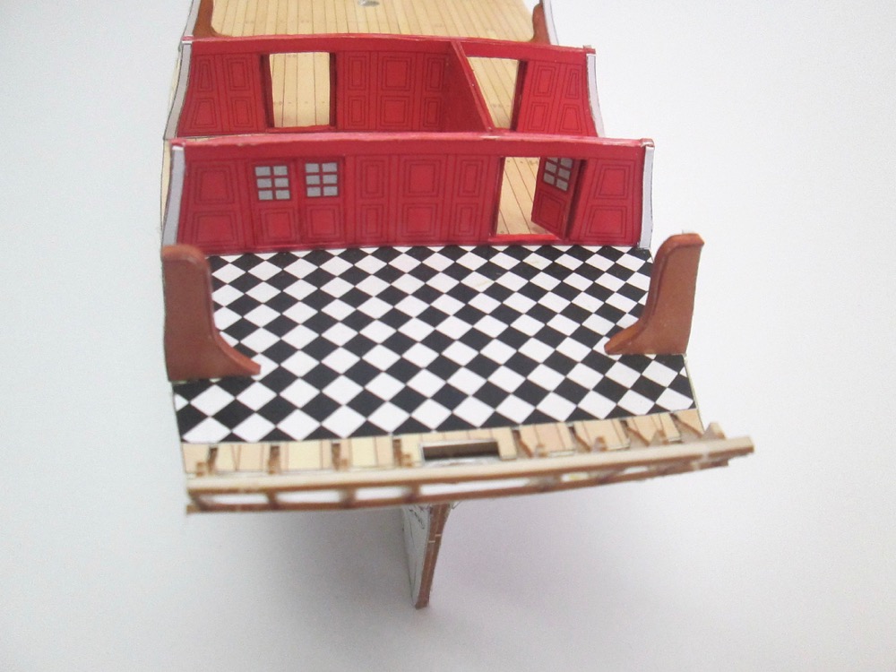
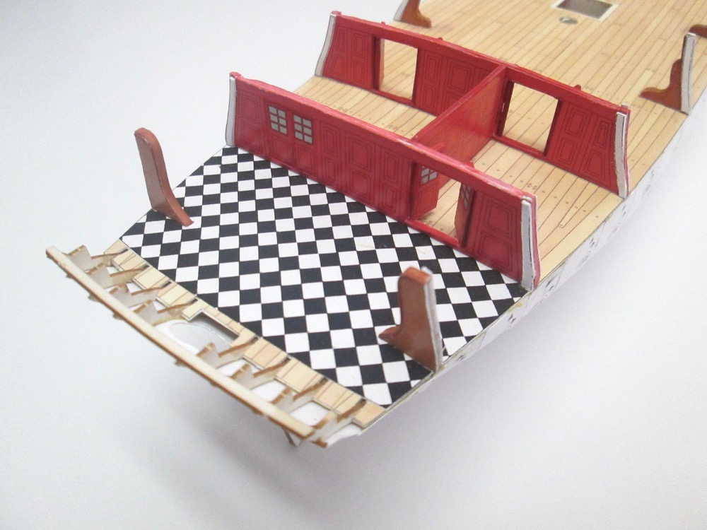
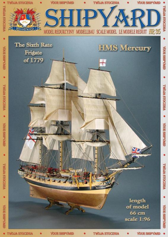
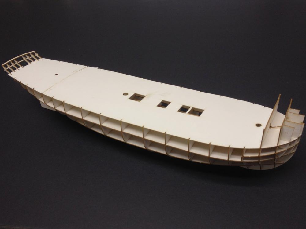
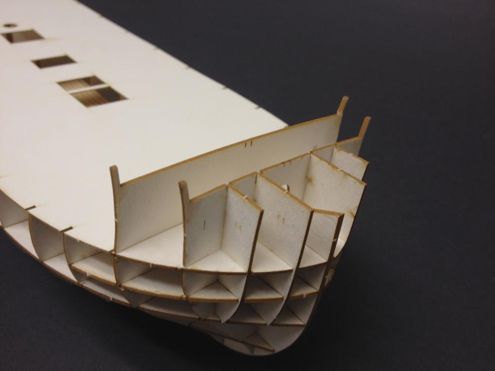
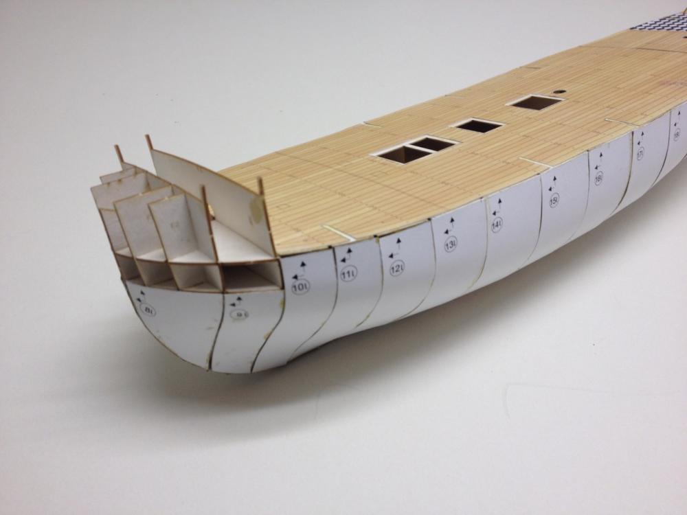
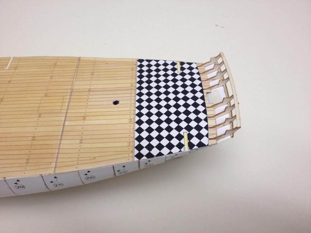
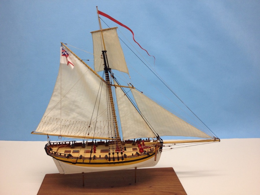
Having completed HMS Alert, which is now safely in a case, I'm left with a kind of paper emptiness... I have plenty of projects, but I'm so accustomed to having a paper model project in the works that it just didn't seem right to not have one now. So, I've taken on the 28-gun Enterprize-class 6th rate frigate HMS Mercury. Shipyard (Vessel) makes 2 versions of HMS Mercury. One is a 1/72-scale boxed kit with laser-cut parts and all the fittings, brass cannons, resin figurehead, wooden spars, cloth sails, plus paints, brush and rigging line, etc. However, that version is a lot pricier than the simple 1/96-scale paper model where you have to cut everything out yourself. I got the latter from Ages of Sail for around $40. The kit includes pre-printed parts that you have to cut out, plus laser-cut framework that makes hull-construction very quick and accurate. I've actually had this kit for quite a while, probably at least a year or more. I also started it some time ago so I would have a hull that illustrates how these kits go together. I was going to just do a partial start and give it to Ages of Sail as a demo model. But, that never happened. As I got further along on the Alert, I thought about how interesting a larger ship might be. Also, knowing the complexities of a 3-masted square rigger, I thought I might just build this as a kind of admiralty style model. Possibly building a launch ways and adding pole masts for the launching flags. In fact, right now, that's my plan unless I eventually change my mind and decide to rig this model. The kit includes some 15 pages of printed parts, the laser cut framework, several sheets of drawings and templates, including patterns for making sails. Printed parts are included for two different color schemes. The completed, fully rigged model, measures about 26" long. The hull itself is just about 16" long. I put the hull framework together many months ago. It goes together very easily and takes very little time. More recently, I started putting on the first layer, which basically turns the model into a hollow solid hull model. As you can see, I also added the deck. The parquet floor is a separate piece which sits on top of the wood-pattern floor. Lastly, over this past weekend, I wanted a distraction, so I started working on the cabin partitions. I have to say that this is one advantage that these paper models have over their wood counterparts – there is much more internal arrangement provided in these kits. It even includes furniture for the great cabin. So, there you have it. Another paper model begun. As I said earlier, this isn't a priority project, just something I'll tinker with over time. But, like HMS Alert, it may very well get to the point where it takes on a life of its own and demands more of my time to take her to completion. Clare


- 82 replies
-
- 29
-
-
ratlines-At what scale do you just use an overhand knot?
catopower replied to bear's topic in Masting, rigging and sails
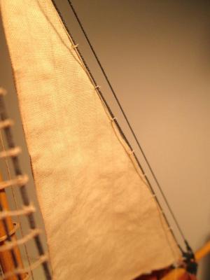
Like John, I clove hitch down to 1/96 scale. I prefer the way the ratlines hang when tied with a clove hitch. If you use an overhand knot, the line on one side of the knot hangs nicely, but on the other side, it starts with an upward wave. Below 1/96, I would probably just consider gluing. But then, I've never built anything with ratlines smaller than 1/96. Clare -
Thanks again everyone for the kind words. Druxey, I'm like a stealth ship modeler. Nothing... nothing... nothing... then whammo! But, seriously, HMS Alert is officially complete! I just adding a bunch of rope coils and have the case nearly finished. The case is an acrylic box which will be brass trimmed, and it will set on a cherry base. I'm ship modeler, not a woodworker, so don't anybody expect too much. I hate building cases. But, it's necessary to keep the model save. Plus, if properly done, it "frames" the model nicely, and makes it look more valuable. The model will have a home with a fellow ship modeler who's been admiring it and inspired me to take it to completion – it started as just an experiment on paper model making. However, we've made arrangements for me to take it to the NRG Conference in San Diego this October. Having felt a kind of strange separation anxiety from paper model making now, I've decided to move forward on another one to work on in the background, the 1/8" scale HMS Mercury – not the expensive, larger boxed kit, but the smaller CHEAPER paper model. I purchased the kit from Ages of Sail and picked up a "Super Detail Kit" for it from GPM. The detail kit includes gun carriages, capstan, gratings, ships boats, and some other parts in laser-cut cardboard. Most importantly, it provides laser-scribed scrollwork/figurehead so that's not so 2D, plus some nice laser-cut parts for the stern gallery lights, which are just printed paper in the basic kit. I'll start a build log on it in the near future, but I'm focussing my attention to other projects I need to get done. I will probably get far enough along by October to show it off at the Ages of Sail table at the Conference. I'll post the remainder of the HMS Alert photos in the Gallery. Thanks everyone for following my build! Clare


- 121 replies
-
- 29
-
-
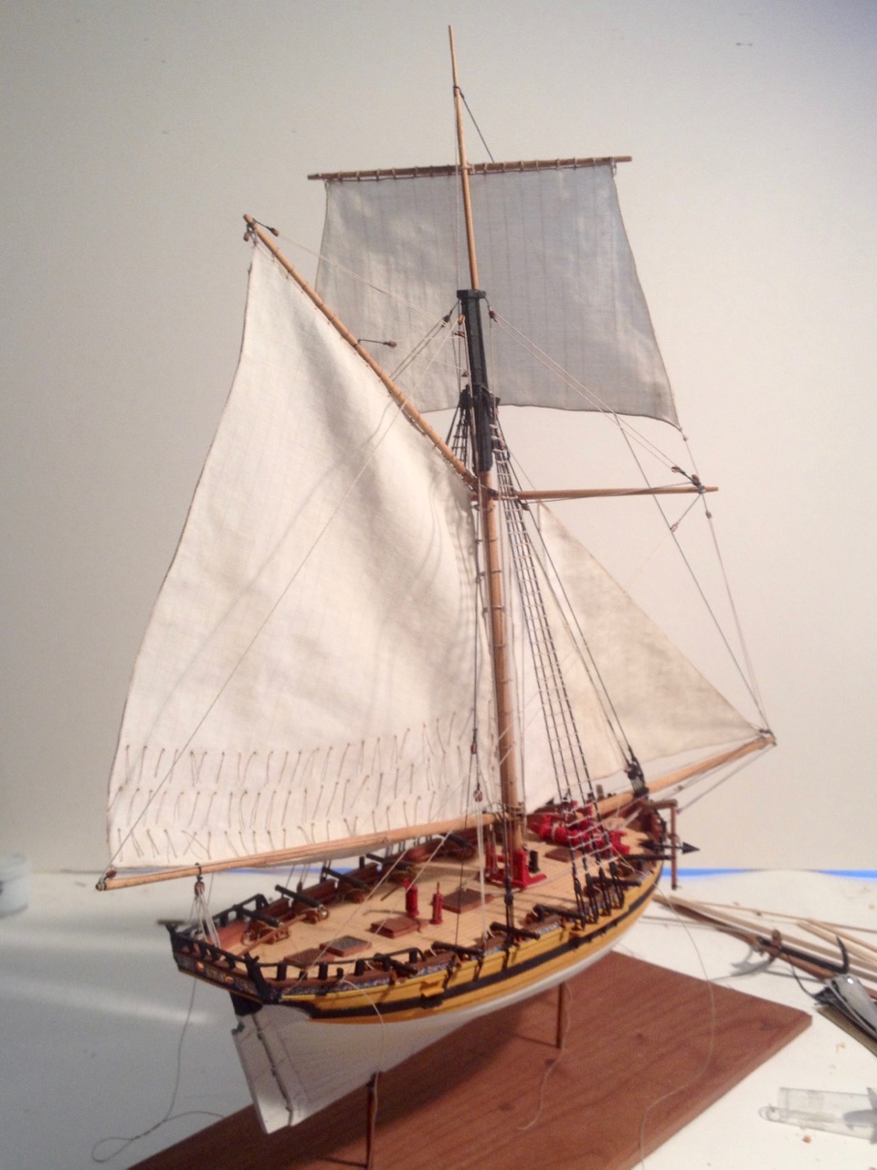
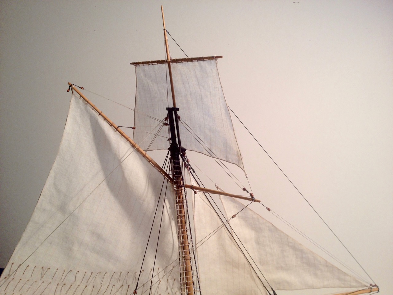
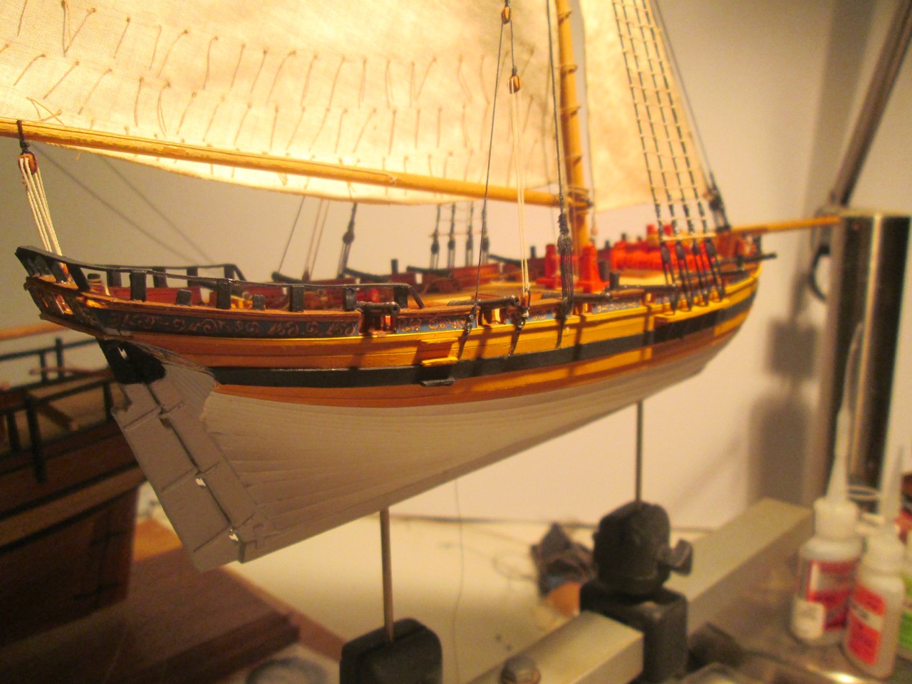
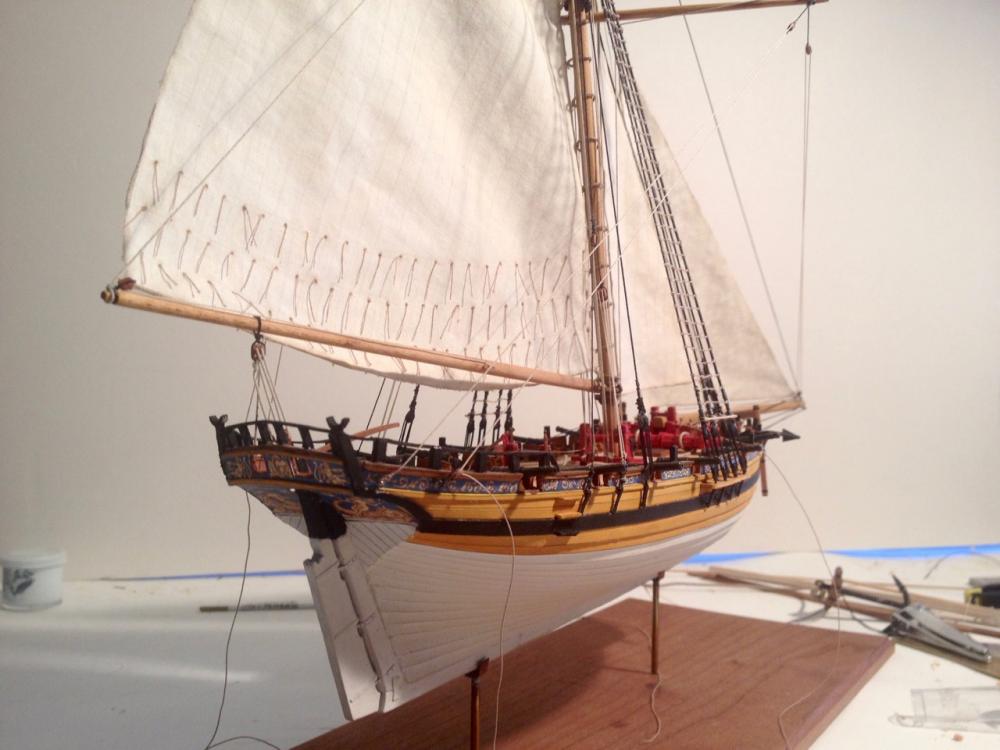
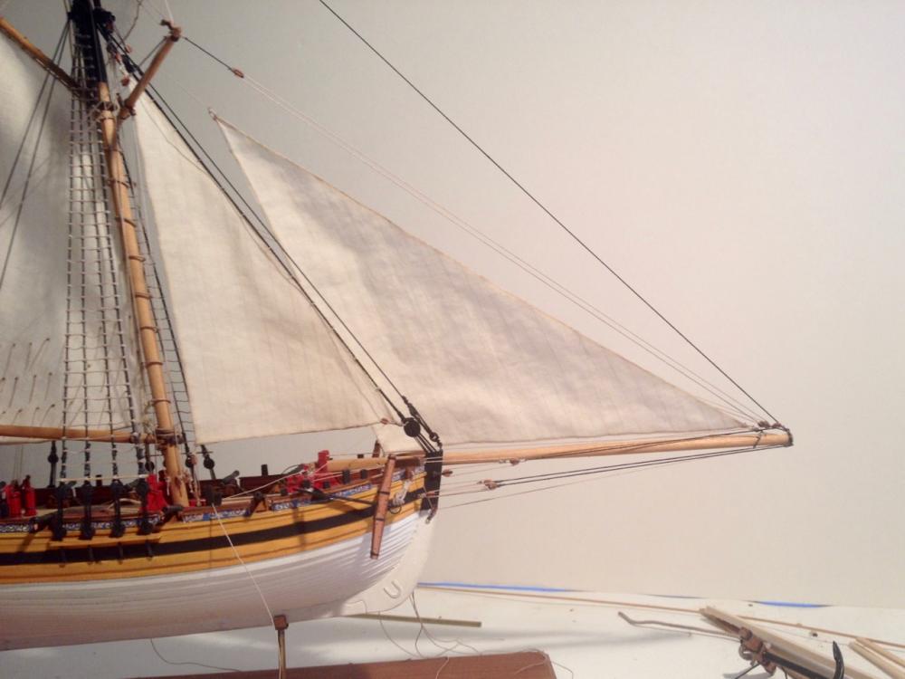
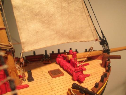
We're VERY close now! I finally finished building up the fashion pieces and boom crutches at the stern. This was the probably the part that took the most creative thinking of the whole model. The paper fashion trim didn't fit due to construction variation in my model – that is, I didn't line up the parts as intended! Also, the drawings weren't very clear as to how the parts fit and just what parts were needed at the rail. This is the reason I'm doing this work after most of the rigging is done. It took me a long time to decide on how to best approach the problem. As it is, it seemed to work out. Luckily at 1/8" scale, the details are too small to really discern any problems. Or rather, if there is a problem, my eyes are worn out enough that I can't see them. Rigging is nearly complete now too. I just added the braces to that topsail spreader yard and just need to secure them once the positioning seems good. Next, I'll need to add braces to the small upper yard. The hardest part of the rigging now is really just how to secure the sheets for the jib. Not that difficult, just requires a little more thought because of how low I have mounted it. Last thing will be to add the flags and their halliards. Should have things wrapped in another week or two! Clare

- 121 replies
-
- 20
-
-
Some criteria for starting a new group project
catopower replied to Chuck's topic in Group Projects on Model Ship World
Carving is great idea and so is sailmaking. But there is one subject that I would absolutely sign up for on a group build, and that is making figures for ship models. I've tried making figures before, I have a couple books that talk about it, but I haven't been very successful at it. Would love to be able to make figures in 1/8" scale, 1/4" scale, and even 1" scale. Clare -
Or worse yet, in order to minimize costs, they adjust the scale based on what will fit into standardized packaging designed to simplify shipping and distribution. Then again, reducing costs for kits that so many people complain about being excessive, may not be so terrible (?). Clare
-
That's excellent news Daniel! You must now have a HUGE pile of work ahead of you. Are the Mini-Mamoli kits going to continue to use pre-carved hulls? Just curious. I expect to find out that you'll be locked away in a ship model kit designing dungeon for many months to come! Best of luck with the new product line. I'll be looking forward to seeing the new re-releases. Clare
-
Hobbie, A lot of the mantua kits come that way. It was a very early way of providing etched brass parts. You're going to want to first cut the parts to the outer blue (thick) edge. Don't cut too close – use a file to finish the edges. For some of the larger parts, in particular the ones that have multiple windows, I think you're going to have to cut them further, like to the inside of of that blue border, but check the fit of the part, to make sure first. You're probably going to want to paint instead of leaving it all as plain brass. The blue is, I believe, a residue coating that protected the metal from the acid bath. You can remove it by using a very find sandpaper. Paint the recessed areas as necessary. If you like the coloring of natural brass for the raised areas, just lightly sand away any paint you got on the raised areas. Otherwise, paint the raised areas carefully. Clare
-
Thanks again all for the nice comments. Sorry, it's taken me so long to come back here. Once I got the model off the workbench and onto the shelf, I got preoccupied by the next piece of business. For one, I just wrote up a piece for the Nautical Research Journal. Hopefully, it will make more people aware of this wonderful kit. In the meantime, I know of two others who will be building the Tosa Wasen kit and I hope to see a build log from one of them soon! mwb?? For the record, I'm tinkering with the construction of a 1/10-scale Japanese traditional boat workshop display. It's really just the framework of the shop with much omitted for visibility. I'm not sure how interesting it will end up. I'm still tinkering with ideas. If you don't know anything about how these boats are/were built, you should visit Douglas Brooks' blog and/or buy his book: http://www.douglasbrooksboatbuilding.com. To get to his blog directly, visit http://blog.douglasbrooksboatbuilding.com. He was just in Japan for a couple month building a rice field boat for a museum up on the Noto peninsula and another boat, from Northern Japan I believe it was, for a museum in down in Kobe. The boat I'm going to piece together for the boat workshop is an Urayasu Bekabune, a small fishing boat used on Tokyo bay. You can find more info about the boat on Brooks' website. The one for the boat workshop display will be only partially built, since the idea is for an "under construction" scene. But, I'll complete another one, since at some point in the project, I'll know how. And, it's a very simple type of boat – much simpler than the Tosa Wasen. Clare
- 51 replies
-
- 5
-
-
- wasen
- thermal studio
- (and 1 more)
-
1/10-scale Japanese Fishing Boat kit from Thermal Studios
catopower replied to catopower's topic in Wood ship model kits
Oh, I DID see that! I don't know what I was thinking. Apparently, I was not. Thanks for the wake-up call wefalck! Clare -
1/10-scale Japanese Fishing Boat kit from Thermal Studios
catopower replied to catopower's topic in Wood ship model kits
Thanks Wefalk, I actually saw the cover in the last issue of the Nautical Research Journal, so I visited that website and ordered a copy. It took me a while to translate from French, but found it an interesting Part I. I'm looking forward to the other parts of the series. One thing that wasn't clear to me was the name of the author. Do you know who wrote it? Clare -
1/10-scale Japanese Fishing Boat kit from Thermal Studios
catopower replied to catopower's topic in Wood ship model kits
Hi Mark, I'm glad to hear that you're getting the kit. I'm only just starting to hear from people who are buying the kit. You're the second person in a week that I've heard from. FYI, the other person tried emailing info@thermal-kobo.jp and waited a week with no reply, so he emailed shop@thermal-kobo.jp and got a reply within 24 hours. Here's his post on Model Space: http://forum.us.model-space.com/default.aspx?g=posts&m=189319post189319 The link you provided didn't work for me, but this did http://thermal2.exblog.jp/i65/ without the 1// at the end. If this is the page you're referring to, that's Douglas Brooks sitting next to Masaki Tanimura, who runs Thermal Studio. Douglas had mentioned seeing the Tosa Wasen model, a few years ago, but didn't remember any details about it. I know he stopped in Kochi City a few years back and stayed overnight with a friend who created the drawings that the kit is based on. I think this photo is from that visit. Looking forward to seeing your build log! Clare -
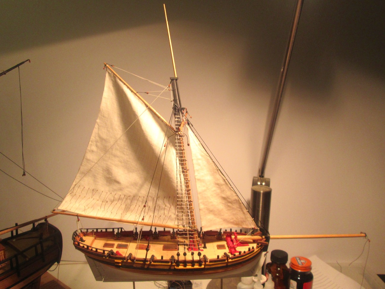
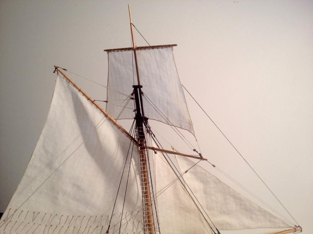
Thanks Cog. I made a bit more progress this past week, though it doesn't really look like it. I finished rigging the lines dealing with the main sail, and added the staysail, halliard and downhaul, added brace pendants to the topsail yard, and then some. Plenty more to do still. I have a lot of bowsprit rigging to deal with, plus the jib and squaresail to add. Also have a little bit of hull details to add and a few small deck details. But, it's getting there. Clare


- 121 replies
-
- 16
-
-
Hi grsjax, Ages of Sail carries their kits as well as kits they make for other companies like the Nordic Class Boats line. I thought they looked similar in production style and quality to Dusek kits. The Panderma that Thanasis posted a link to (a build) seems pretty popular. The Mariefred (a Nordic Class Boats kit) won some kind of best product award in Germany last year. They do have some unusual subjects, which is really nice. Clare
-
Tony, What a fantastic job you are doing on this build. The only negative comment I can make on this blog is that there is only a LIKE button, when there should be a LOVE button! A masterfully built model. I hadn't looked in on it before, but now I'm going to have to go back to the beginning of your blog and start learning how to build a ship model the right way. Clare
- 269 replies
-
- 2
-
-
- Caldercraft
- First build
- (and 3 more)