Bob Cleek
-
Posts
3,374 -
Joined
-
Last visited
Content Type
Profiles
Forums
Gallery
Events
Everything posted by Bob Cleek
-
One could use a matte varnish, but, I'd suggest you consider a single coat of clear shellac. It will dry much faster than any varnish and leave no gloss on the wood, unless you let it puddle up on the surface. Matte varnishes can be tricky. The flattening agent is basically "dust" and it settles in the contaiiner. If it is not fully stirred before application (and after, if you are taking your time,) and the flattening agent settles, taking varnish from the top of the can can result in a gloss finish. Shellac cleans up with alcohol and is totally non-toxic. Alcohol fumes are harmless. Varnish will provide a more durable finish, but the surface of a model won't be getting a lot of abrasion in use, so that doesn't matter. Shellac is also a lot cheaper than varnish and, given the synthetic varnishes not being sold, we know shellac is an archival material, while the modern varnish coatings may not be. Besides, if you don't like the shellac, you can varnish over it. Shellac over varnish, not so much.
-
Different boats, different rigs. That's an odd one for her size. A lot of strings to pull for such a small boat. It would be interesting to know more about what type of vessel it is. It's not quite clear from the photo exactly what is going on. Apparently, the boat is rigged so that all sails can be handled from the cockpit, more or less. There appear to be brails on the main and the headsails. It appears that the mainsail is designed to be brailed and the gaff left hoisted, something like the Thames barges were rigged. It's a small boat and doesn't appear to have any shrouds at all, but with so little sail area, she wouldn't need them if she carried a solid mast. What is unusual is that her gaff jaws ride above what would be the hounds if she had shrouds. In this case, the jaws are above the mast bands and the topmast doubling. The jaws would chafe something fierce on the doubling, I'd expect. I also note that there is no throat halyard tackle shown in the picture. I wonder how one gets up there to bend the sail onto the gaff boom, or lace the luff. Unless this is only a partial drawing, or there is some other explanation, I'd say there's something wrong with the picture. Was this drawing from the instructions in some kit? Was it a Chinese kit? I'd like to know what others think. Can you tell us more about the documentation you've got there?
-
YTL-45 Taiwanese Navy tugboat by Erik W - FINISHED - 1/350 scale
Bob Cleek replied to Erik W's topic in Plastic model kits
Mind boggling! Amazing work. Thanks for sharing it with us. -
Rare complete ship's curves set on eBay
Bob Cleek replied to Bob Cleek's topic in Modeling tools and Workshop Equipment
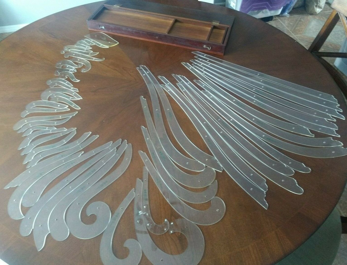
Drawn ship plans came rather late in the game at the end of the Seventeenth Century. Before then, vessels were often built by "rule of thumb." From experience, the size of the parts were described in relation to each other. A mast would be as long as the ship was long on deck. The mast would be placed in the middle of the keel's length. A bowsprit would be the length of the distance from the mast to the stem, and so on. The shape of a hull would be defined by a midship mold and perhaps a couple of molds half way between midships and the stem and stern. These molds would be saved and kept as patterns for later builds, or modified in shape a bit, if they thought that would improve the ship. If a ship was "tender," they'd build the next one with a bit shorter mast or with a bit wider beam, or both, and so on. Once the molds were set up on the keel, temporary battens would be bent over the molds to define the shape of the hull and the framing made to fit the shape defined by those battens. During the "Age of Enlightenment," when scientific analysis began, they discovered there were rules of physics that determined the properties of a sailing vessel's performance and they reduced these rules to mathematical equations. This made designing ships on paper possible and practical. They didn't have to build a whole ship to see how she sailed. They could actually calculate the displacement of a ship, its center of effort, metacentric height, center of effort and so on and mathematically calculate, for example, how large the area of the rudder should be, how much weight it could carry, and whether the hull could stand up to a given area of canvas. When they started drawing, they started developing specialized drawing tools to make that job easier. Fair curves were originally and always continued to be drawn with battens and weights. Some curves were too tight to easily be drawn with battens, though. Draftsmen always used templates to draw repetitive shapes. The "ships' curves" and other curves eventually evolved to represent mathematically defined curves when the interrelationship of different mathematically defined curves were discovered by mathematicians. The ships' curves as they ultimately came to be, were, of course, intended as an aid to drawing the plans, but not just as a matter of "neatness." Far more importantly, they were a matter of ensuring mathematical "fairness" in the development of the shapes that were being represented in the drafts. Using curves made it not only possible to draw neat lines, but to efficiently draw lines that were fair.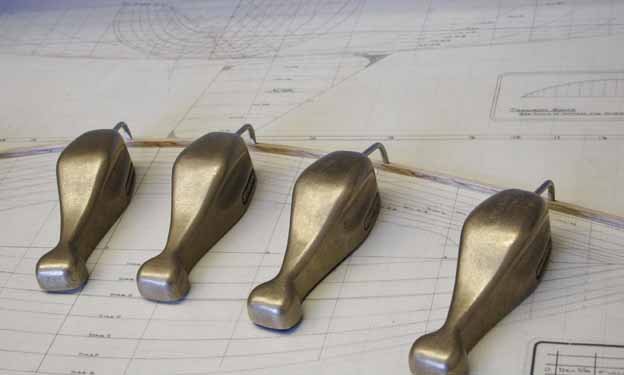
-
Rare complete ship's curves set on eBay
Bob Cleek replied to Bob Cleek's topic in Modeling tools and Workshop Equipment
Well, I'll be... I just came across a German art supply house that is selling about forty or so of the original numbered Copenhagen curves. https://www.mp-artware.de/shop/en/Templates/Ship-curves/ These must have come back on the market fairly recently. I'll bet there's money to be made in the short term buying up a bunch of them and selling them as near-complete sets on eBay! As you can see from the above posts, or by going on line and googling a better chart of them, you can see what you might be missing. -
Rare complete ship's curves set on eBay
Bob Cleek replied to Bob Cleek's topic in Modeling tools and Workshop Equipment
I've never found any citation to academic authority answering that question. I do have a theory, though. There are different types of "curves." Specifically, there are ship's curves, of which the two most common sets are "Copenhagen curves" and "Dixon Kemp's curves." There are "irregular curves," also called "engineering curves" or "Burmester's curves." And there are "French curves." (I don't know why they were called "French curves." The British always seemed to add a place-of-origin adjective to anything from elsewhere. Perhaps it was intended as an insult, much as they called condoms "French letters" and syphilis "the French disease." Burmester designed the now-classic set of 28 "irregular curves" bearing his name in 1904, at least 150 years after the differently-shaped "ships' curves" came into common use. "French curves" were also in existence long before Burmester designed his curves. Of Burmester's set of 28 "irregular curves," three are the most commonly encountered today and are still in production and sold in art and stationary stores, often incorrectly labeled as "French curves." Burmester's curves are mathematically defined curves designed to solve mechanism solutions for full link rotatibility, compactness criteria, and feasible transmission angles in multiple position linkage mechanisms. (Or so says one research paper.) Each curve is defined by algebraic equations. Beyond that, it's way above my pay grade! In summary, Burmester curves can be used to draw fair curves in the same way as French curves or ships' curves, but they were specifically designed for use in mechanical engineering to design linkage systems. As far back as we know, patterns and templates were used in shipbuilding by the Romans, who built fleets of sister ships from standardized full-size lofting patterns. The use of drafting curves in naval architectural drafting appeared in the Eighteenth Century contemporaneously with the practice of drawn ships plans demanded by the development of scientific approaches and the use of theoretical models in naval architecture, which previously had been an exercise in trial and error and "monkey see, monkey do." In Western Europe, at least, the "Father of Scientific Naval Architecture" was Fredrik Henrik af Chapman of Architectura Navalis Mercatoria (1768) fame. Chapman devised the "parabola method" of ship construction and design, which identified the relationships between certain fair curves and their effects on speed, stability, and the displacement of ships. (Increased stability was a huge advance. More displacement and stability meant more guns could be mounted and higher above the waterline, which meant they could open the gun ports in heavier weather.) It may be presumed that as Chapman's scientific curves were adopted as part of the naval architect's lexicon, curve templates for drawing them were created. Chapman's curves were, like Burmester's, defined by algebraic equations, but for different purposes. I suspect we have Chapman to thank for the English term "Copenhagen" curves. Chapman's theories certainly occasioned their invention even if that was by someone else. Chapman was an interesting fellow in many ways. He was a self-made shipwright who virtually invented scientific naval architecture, going back to school to learn the cutting edge mathematics of his time. In the mid-1700's, as most know, Western Europe was in political flux and wars were commonplace. Chapman was British, but born in Stockholm, Sweden, to a British father. He traveled around, studying the shipbuilding practices of the various nations' navies. At one point, that landed him under house arrest in Britain, which considered him a bit too cozy with the French, and, right after that, tried to hire him to design ships for the Admiralty. He almost did, but then took a similar job with the Swedish. In those days, his ability as a warship designer made him the Werner von Braun of his day, with nations so eager to secure his technical expertise that his prior political affiliations were ignored. But Copenhagen is in Denmark, not Sweden, and Chapman worked in Stockholm. That is so, but from 1397 to 1523, all of Scandinavia had been united under the flag of the "Kalmar Union" and Norway continued to be united with Denmark between 1524 and 1824. Copenhagen was the capitol of the Kalmar Union and the Norwegian-Danish Union. It's reasonable to conclude that Chapman's technology was common to all the Scandinavian nations and, from the perspective of England, anything coming from Scandinavia might be called "from Copenhagen" in much the same way the world refers to "Washington," "London," or "Moscow" to reference the U.S., Britain, or Russia. And so, they became "Copenhagen curves" because that's where the English thought they came from. They already had "Stockholm tar," so maybe they thought they'd spread the credit around and call them "Copenhagen curves." At least that's my best guess. Can anybody shed any more light on the subject? -
Rare complete ship's curves set on eBay
Bob Cleek replied to Bob Cleek's topic in Modeling tools and Workshop Equipment
Go for it. From what I gather, though, the machine time it takes to make the cuts costs more than they can be sold for. -
Rare complete ship's curves set on eBay
Bob Cleek replied to Bob Cleek's topic in Modeling tools and Workshop Equipment
Go for it! -
Rare complete ship's curves set on eBay
Bob Cleek replied to Bob Cleek's topic in Modeling tools and Workshop Equipment
I do the same with mine by putting a piece of masking tape or Post-it note on the top face of the curve and marking that. As for cutting them on a CNC machine, the guy who had the "Kickstarter" site to do exactly that couldn't generate enough interest to get tooled up and into production. I don't know why beyond that, though. (See: ) -
Rare complete ship's curves set on eBay
Bob Cleek replied to Bob Cleek's topic in Modeling tools and Workshop Equipment
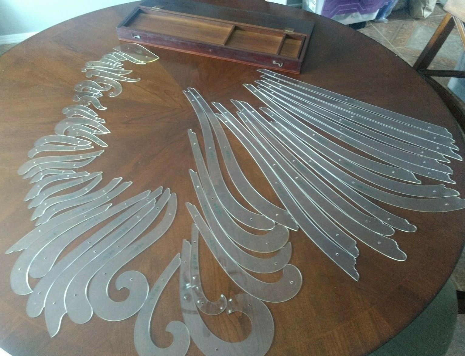
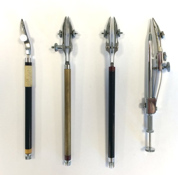
As mentioned, There are 56 curves in the standard Copenhagen curves set. There are many other types of curves, sometimes called "French" curves. These can be found in the old K&E catalogs, one of the more recent ones from the 1930's is found at http://archive.org/stream/pricelistcatalog00keuf#page/231/mode/1up The curves begin at page 231. The Copenhagen curves are at page 234 and following. The short answer is that, yes, you just have to "try and fit" to get the right curve. The method of use is illustrated below. A curve is defined by a series of "points" (dots) which would in the case of a ship's lines, come from the Table of Offsets, or from measurements from original plans, if one were copying those (usually when changing the scale of the drawing, generally using a pair of proportional dividers.) When the points are laid out, the curves are selected so that they coincide with as many points as possible. sometimes points will be out of position slightly and this indicates that the curve defined by the points is not fair, in which case, the curve will define the fair curve. The curve should "touch" at least three points and preferably more. A French curve is being used to draw the curve in the illustration below. The illustration is of the use of a single French curve. There is no rule against using multiple curves. They are designed to be used that way, such that if they touch at least three points in common, the two curves will define a fair curve when joined at such an overlap. It can be seen that in "A" below, the curve is touching points one through 4. The line would be drawn that far and then, in the illustration, another curve section of the French cure is used to draw points 3, 4, and 5, and in "C" has been manipulated again to draw from point 5 to point 6, and in "D" to draw between 6 and 7, in "E," using the inside of the curve, to draw from point 7 to point 9 and finally in "F" moving the curve again to draw the line from point 9 to point 11, thus drawing the shape intended with a fair curve. In each instance, the curve was moved to see if it fit a number of points. The "eyeballing" to fit the curve isn't as complicated as one might imagine, except in complex curves like the one illustrated below which required six segments to be drawn from six positionings of the curve. Working with lines drawings, it's not too difficult to find a curve, or collection of curves, to meet your needs. When inking drawings, which in the old days was done with India ink and a "ruling pen," the draftsmen would tape coins or washers to the face of the curves being used so that the edge of the curve was raised slightly above the paper or drafting linen. This space prevented ink "wicking" beneath the edge of the curve and ruining the drawing. Curved lines were drawn using curves with a "curve pen," which had an offset nib which swiveled on a rod running through the center of the handle. This feature kept the pen point always "trailing" and oriented parallel to the edge being used. In this fashion, the width of the curved line would always be the same, being the distance set by adjusting the space between the nibs. The pen on the left in the picture below is a single point curve pen. The two middle pens pictured below are "railroad" curve pens which, by means of a double pointed head, will draw two curved lines simultaneously and as wide and as far apart as the user wishes to adjust them. All three curve pens can be used as regular ruling pens by tightening the knob at the end of their handles. This prevents the heads from swiveling when its tightened down. The third pen pictured is a drop point compass pen which is designed to ink very small circles. The needle point plunges down the center tube and the pen point rotates around the needle point on the tube. These were also called "rivet pens," because they were originally designed and used for drawing rivets in iron construction drawings.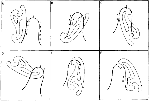
-
Rare complete ship's curves set on eBay
Bob Cleek replied to Bob Cleek's topic in Modeling tools and Workshop Equipment
Beat me to it! That's a copy of the Keuffel and Esser catalog page showing the Copenhagen curve set. There are 56 curves in the standard "Copenhagen curve" set. Check out the old K&E catalogs on line and find the details. Here's one: http://archive.org/stream/pricelistcatalog00keuf#page/231/mode/1up They were sold as sets, but I believe they could also be ordered individually. Each curve has a K&E part number on it. The famous British naval architect, Dixon Kemp, designed a set of ships' curves, as well in the late 1800's. Kemp's curves were sort of "egg" or "kidney-shaped" and nested inside of each other with three or four "rings" to a set. The sets, of identical shapes, came in two sizes. I've seen pictures of these in books, but have never seen them in the flesh. They were a British item and apparently never caught on in the rest of the world. -
I read somewhere, but can't recall where, that there were more than a few broken ankles caused by cannon balls coming adrift and rolling across the decks. Getting whacked in the ankle with a rolling cannon ball would have to smart a bit, I'd expect!
-
Launch day for the Falmouth Pilot Cutter is coming up soon
Bob Cleek replied to Chuck's topic in Nautical/Naval History
I don't think they edge-set those planks with a big travel steam iron, though! -
Byrnes Sliding Table -Input Requested
Bob Cleek replied to glbarlow's topic in Modeling tools and Workshop Equipment
Naw, I'd award that prize to the chainsaw. Fact is, all tools are dangerous and forgetting that is the major cause of injuries. The liability insurance bean counters will tell you that the tool that sends more people to the emergency room than any other is the ladder. No kidding. That's a fact. -
Rare complete ship's curves set on eBay
Bob Cleek replied to Bob Cleek's topic in Modeling tools and Workshop Equipment
You'd think so, but actually they are made of "Luxite," K&E's trade name, which is apparently a type of plexiglass plastic material. The early curves were made of boxwood, ebony, and pearwood. In the mid-1800's, some were made of hard rubber. They were essential to drafting plans in naval architecture, aviation, and automobile design before CAD became available and, even now, only the most sophisticated (and expensive) CAD programs are capable of approaching what Copenhagen curves can do, often much easier and faster than CAD, as well. CAD caused a drop in demand for them below what was necessary to make producing them profitable. Demand for mechanical drafting and surveying instruments dropped dramatically as the industry "went digital" and K&E filed for bankruptcy in 1982. The trade name was purchased by others, but nothing was done with it and that was the end of the high-end drafting instrument industry in the U.S, at least. The European manufacturers lasted only a few years beyond that. There's always been a demand for manual drafting instruments, and when the sources dried up, the value of existing instruments eventually skyrocketed when collectors entered the used instrument market. Curves sets, first marketed by Keuffel and Esser right after the Civil War, were never inexpensive. While they may not appear so, they are precision instruments that must exactly replicate mathematically defined fair curves. One fellow attempted recently to produce Copenhagen curves as a "Go Fund Me" business, but failed to get enough financial support to pay for the tooling to commence production. Complete sets are very difficult to find these days and people do pay a lot of money for the few sets that come up for auction now and again. A CAD program that can come close to what can be done manually with curves will set you back a lot more than what the curves are going for now and likely require a steep learning curve to master. -
Byrnes Sliding Table -Input Requested
Bob Cleek replied to glbarlow's topic in Modeling tools and Workshop Equipment
What I meant was that if you wanted to cut pieces of wood all exactly the same length, the sled does that very easily. If you want to cut perfect miter angles, the sled does that better than using the miter gauge on the table saw and poses less risk of your touching the moving blade. -
Mantua electric scroll saw.
Bob Cleek replied to Moab's topic in Modeling tools and Workshop Equipment
From the photos and what little information is on the Mantua website, it certainly doesn't look like much for the money and the price doesn't include the power supply you have to buy separately. I may be wrong, but judging by the picture, it's little more than a toy. Given what they are asking for it, one could buy a decent entry level scroll saw new and probably pick up a very good one on the used market. (Lots of people buy scroll saws and then abandon the hobby they bought it for.) There's a world of difference between a bottom-end scroll saw and a top-of-the-line one and good reasons why the best are so much more expensive than the least of them. I'd look for something more substantial. If money is a consideration, spend what you would have on the Mantua and its power supply to buy a good used one. I think you'll be glad you did. -
Rare complete ship's curves set on eBay
Bob Cleek replied to Bob Cleek's topic in Modeling tools and Workshop Equipment
You and me both! I've also got complete sets of K&E French curves, engineers' curves, and "railroad" and "highway" radius curves. I've got a fair number of "doubles" to the ship's and French curve sets. I had to buy "odds and ends" in lots before I got all of them. I built them up over a period of three years or so when the stuff started appearing on eBay and before collecting it got really popular. I built quite a collection of top-of-the-line K&E Paragon drafting instruments. It started when I first bought a K&E Paragon planimeter to calculate displacement and I went downhill from there. I finally "admitted I had a problem" and "got into rehab" when the prices started climbing exponentially. -
Somebody's selling an extremely rare complete cased set of Keuffel and Esser "Copenhagen" ship's curves on eBay. (Not me. I've no dog in the fight. I already have a set.) I thought some MSW forumites might be interested in seeing what a set looks like. Similar to "French curves," these "mathematically shaped" curves are used in the same manner as "French curves" by naval architects to draw fair curves when drawing ships' lines. Sometimes called "Copenhagen curves," when used in conjunction with one another to join points laid out on the drafting board, they will permit drawing a fair curve of any shape whatsoever. Dealt a death blow by CAD, like a lot of essential manual drafting instruments, they are no longer made and are unobtainable on the retail market. The perfect gift for the scratch-builder who has (almost) everything! A steal at a "buy it now" price of only $600! (Insert "sarcasm" emoji here.) https://www.ebay.com/itm/Lot-of-56-Keuffel-Esser-Co-1864-Ship-French-Drafting-Curves-With-Box/183690539257?hash=item2ac4cf30f9:g:9tcAAOSwGFZcae~q Thirty-one "watchers" and nobody's bought it yet. It'll be interesting to see what it ultimately brings when the seller wises up (or gets lucky.) It's worth watching (click on the "watch" feature to track it) to see what happens. I'd have guessed it would have been priced between two and three hundred, at most. The collectors can get crazy sometimes, though. I didn't pay anywhere near that for my used set, but that was years ago before manual drafting instruments became hard to find and highly collectible. There was a brief moment in time right after everybody went over to CAD and had no interest in manual instruments when even the finest manual instruments in mint condition could be bought for peanuts. Like vinyl records, the advantages of manual instruments have been rediscovered and are now highly prized by collectors and users alike.
-
For those with a collector's taste, acquiring a classic Keuffel & Esser boxed set of "scales," as they are properly called, might be a joy. The complete boxed sets in good condition are somewhat rare and bring a premium, but single rules are frequently offered and sell at quite reasonable prices on eBay. The old-fashioned boxwood versions bring more than the "modern" and now-obsolete plastic ones designed for use with "drafting machines." Metal versions are also made. 1/8, 1/4, 1/2, and 3/4 inch to the foot scales are pretty common.
-
Very handy site!
-
Recommendation - First scratch build
Bob Cleek replied to Bill Hill's topic in New member Introductions
If you feel you are sufficiently knowledgeable to build a full-sized vessel from lines drawings, you've pretty much got it licked. You can just pick any of the thousands of ships whose lines and rigging details are are available in print, on line, or from museums and archives and start building. That would presume you had a full command of the nomenclature and an ability to loft patterns from lines and/or tables of offsets and were familiar with construction practices and rigging appropriate to the period of the vessel you want to model. That level of knowledge requires a learning curve that goes far beyond building kits. If you don't have that level of experience, then Underhill's books and similar ones are excellent starting points, although a bit dated now in terms of technology and technique. Consider them a "must have" for your modeler's library. Understand that you will likely encounter difficulties without a decent reference library that contains at least the basics. (Collecting books can get as addictive as collecting tools!) If you aren't already at least an "armchair" loftsman, sawyer shipwright, jeweler, tailor, painter, ropemaker, and however many other trades and crafts are involved in scratch-building ship models, then pick any one of the many practicums that will walk you through a scratch-build of a relatively simple model. Practicums come in the form of on line PFD articles, CDs, and books. (Underhill's Plank on Frame Models is a practicum for a merchant brig, Leon. Longridge's The Anatomy of Nelson's Ships is a practicum for Victory.) Many of the more detailed MSW build logs are pretty much practicums in and of themselves. Be aware, however, that practicums vary in the amount of prior knowledge they presume their readers have. Some will only address unique construction details and, for example, leave the builder to reference another work to obtain details on rigging. From what I've seen, you won't go wrong taking on anything from Syren, Ronberg, or Anscherl. There are some useful articles on the (somehwhat neglected of late?) MSW articles database: http://modelshipworldforum.com/resources/plans_and_research/ScratchBuildingaModelShipgene.pdf http://modelshipworldforum.com/resources/pinnace instructions me.pdf http://modelshipworldforum.com/resources/Chuck Passaro - MS Brig Syren Prototype Build Log.pdf -
Good luck! There's a ton of options. It boils down to, first, do you want an single-action or double-action airbrush? Then, how much money do you want to spend. I'd suggest checking out YouTube for general background and then searching for discussions and evaluations on this forum for specifics. It's a matter of personal preference, really, but the major distinction is what you are going to use the airbrush for. If you just want to use it to apply paint on parts, you may not need the more versatile double-action airbrushes, which, in modeling applications, are best for weathering and shading effects. As with any tool, the best you can possibly afford is the least expensive in the end. My double-action Paasche has given me great service for over forty years now, but is hardly state-of-the-art today.
-
And if you use solvent-based paints and inks, simply airbrush in front of a door or window open to the outside with a fan blowing the air away from your work area and towards the outside and you shouldn't have anything to worry about. All it takes is a bit of air circulation. As the instructions say, "Use in a well ventilated area." There's probably far more dangerous stuff sitting underneath your kitchen sink right now that you use every day without a second thought than anything you'll expose yourself to building ship models. Airbrushes are relatively surgical in their spray patterns. Manufacturers market "spray booths" for airbrushes because they make money selling them. IMHO, they aren't at all necessary for airbrushing. If you plan to spray stuff with hardware store "rattle cans," that's another matter. I'd say do that outside and upwind of the can! That's a lot cheaper than buying a spray booth. It's an order of magnitude sort of thing.
-
I'd like to hear some more evaluations of its performance. My concern is that wooden blocks and deadeyes lack the weight to be sanded evenly in the polishing media used in such polishers. The block sanders which employ sandpaper "paddles" whack the blocks and keep them moving so they evenly contact the sandpaper paddles and sides of the container. With revolving drum rock polishers and "brass polishers" (used by reloaders for polishing firearm cartridges) the weight of the items polished contributes to the polishing as the container is rotated. It's the items' falling in the abrasive media as the container rotates that polishes them. With tiny wooden blocks, they just rotate along with everything else and don't really "rub" against the abrasive media. It's about the weight of the items being polished. Little wooden parts just aren't heavy enough for the mechanics of the thing. At least that's been my experience trying it with a brass polishing machine. Has anybody else had the same experience?