milosmail
-
Posts
90 -
Joined
-
Last visited
About milosmail

- Birthday May 19
Recent Profile Visitors
1,218 profile views


-
Hull sanding and patching was uneventful (but really dusty), and the filler really helped smooth out the area around the counter/rudder area. I patched a few larger cracks and gaps, but I was pleased to find that my primer (from MicroMark) sealed everything pretty well. One more patch/sand session and maybe a second coat of acrilic grey primer, before I move on to next steps (keel, rudder, gun ports, etc.). Then a final coat of primer, and paint the hull exterior. However, I am going back to rigging my Niagara for a while, as I plan to switch back and forth between kits.
-
fill and sand, fill and sand.... I'm going to put a coat of primer on, and see how much more needs to be done. Lots, I'm sure.
-
Here is question on mast features... the fore and main topmasts have an "octagonal swell" just below the trestle trees. Can anyone tell me how you made these? I'm inclined to add stripwood and shape as directed from the plans. Everything else looks pretty straight forward.
-
 Snug Harbor Johnny reacted to a post in a topic:
USCG Harriet Lane by milosmail - Model Shipways - 1:96 scale
Snug Harbor Johnny reacted to a post in a topic:
USCG Harriet Lane by milosmail - Model Shipways - 1:96 scale
-
Cathead reacted to a post in a topic:
US Brig Niagara by milosmail - Model Shipways - 1:64
-
Back to the Niagara. (I spent the past 3 months on a break, started build of the Harriet Lane - a ME kit which shows the transition from sail to steam in the 1850's). It's listed as intermediate, but I would call it advanced beginner as almost all parts including planking and masts are precut. I took the break after getting very frustrated with construction (actually, shaping) the fore and main masts - from the dowels in the kit. I made two really poor quality sets, and decided I needed a break. So, I decided to buy a Preac DB250 mini-lathe, a 4 sided chuck, and a 1/4 inch turning gough.... I could shape masts from square stock but get clean facets at base and peak. I bought some 3/8 cherry lengths online, and after a bit of practise, I got the hang of it. My process was as follows: starting with the 3/8 stock I marked out the shape and taper. Then, using my disk sander, I reduced the peak of the masts to the 1/4 inch tapered flats called for on the plans. I chucked these through the 4 point chuck and used the gough to quickly reduce the rest of the square stock to roughly a round shape with the proper taper. I followed this with a bastard file for initial smoothing, and finally used sandpaper on the lathe for a smooth finish. I left the base at 3/8, and added octagonal shape. I'm very pleased with the accuracy and ease of doing it this way (although I'm out $200 for the lathe). I plan to stain the natural wood section of each mast, with black at the top per plans. I will use the lathe to shape the remaining mast sections and the yards, which I expect will go quickly with a cautious use of various grit sandpaper. So, I'm back at it.
-
GrandpaPhil reacted to a post in a topic:
USCG Harriet Lane by milosmail - Model Shipways - 1:96 scale
-
GrandpaPhil reacted to a post in a topic:
USCG Harriet Lane by milosmail - Model Shipways - 1:96 scale
-
GrandpaPhil reacted to a post in a topic:
USCG Harriet Lane by milosmail - Model Shipways - 1:96 scale
-
GrandpaPhil reacted to a post in a topic:
USCG Harriet Lane by milosmail - Model Shipways - 1:96 scale
-
JacquesCousteau reacted to a post in a topic:
USCG Harriet Lane by milosmail - Model Shipways - 1:96 scale
-
Canute reacted to a post in a topic:
USCG Harriet Lane by milosmail - Model Shipways - 1:96 scale
-
Canute reacted to a post in a topic:
USCG Harriet Lane by milosmail - Model Shipways - 1:96 scale
-
druxey reacted to a post in a topic:
USCG Harriet Lane by milosmail - Model Shipways - 1:96 scale
-
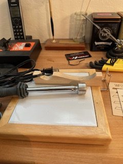
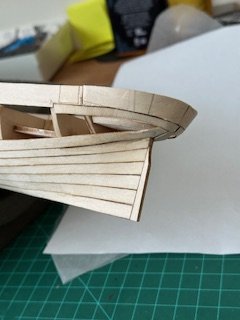
Nearly done planking the hull. But, I had one massive fail. While adding plank 7 to the stern area, one of my clamps and rubber band slipped off, and snapped the stern bulwark extension off, taking half the stern counter material with it! I decided to make a stronger counter from scratch material, by using horizontally grained (rather than the vertical grained provided in the kit) 1/32 left over wood. I used a plank bender to shape the new pieces, removed the shattered counter wood from the broken extension (white glue can be dissolved in 95% rubbing alcohol), and reattached with 5 minute epoxy. Then, having formed the new counter pieces with the plank bender to the exact curve required, it was a simple process to reattach. The new stern counter, with fresh backing, is much sturdier, and I recommend doing it this way. A plank bender is a very useful device (just a cheap soldering iron with a bulbous head) available from Model Expo and other sources for about $20 or so. See photo below. It comes with a cradle and a shaped wooden block for curving. Just soak the wood for a while, then press it into the wooden block with the heated unit until the desired curve is obtained. I got a perfect fit for both pieces. repaired stern Overall, the planking went quickly, but the fit of some pieces was poor. I resorted to patching with scrap wood where gaps were left and sanding in other spots. Each builder will have to deal with this as needed. The final step is filling small gaps with Elmer's wood putty, Minwax wood filler, or equivalent, and then sanding to a seamless finish. One tip: for each plank - be sure you keep track of which side is external, which edge is 'up', and which end points at the bow - especially for the mid-hull sections. Once removed from the billet, it's no longer obvious, so mark orientation on the back...
-
Really lovely work. I hope I do half as good (well).
-
Moving along nicely. I had a bit of trouble with the upper counter (a repeating theme in other posts). The manual says the gun ports should just be marked on the billet, but the manufacturing process has done this by using the laser to burn it in. The material is only 1/32 thick, so the result is to nearly burn through the planned openings on the material. Net, when I went to install the previously soaked plank, it either broke at the gun port seam, or warped badly when it dried out. I went through both starboard pieces and one port, before I found the solution - cut an unmarked piece from spare wood on one of the 1/32 billets, copying the shape from the cutout on billet 6. This avoided the problem of the laser weakened gun ports. - I used billet 6, from which two or three can be made (but watch the grain) - Then, immediately after installing, I added the backing sheeet, also soaked. This stiffened the structure sufficiently to avoid breakage and to prevent any unwanted curl while drying, which was another problem I ran into. I penciled in the positions of the gun ports before I soaked the blank material. I have installed all the backing material without incident, cut off the tips of the bulkhead frames, and I am now in the process of trimming down the bulkhead extensions to the thickness of the strips previously added, making them flush. On to step 10 tomorrow.
-
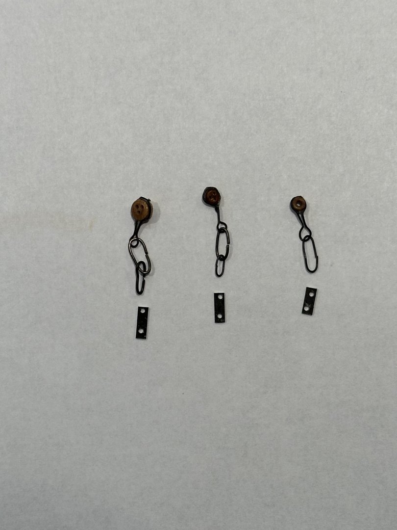
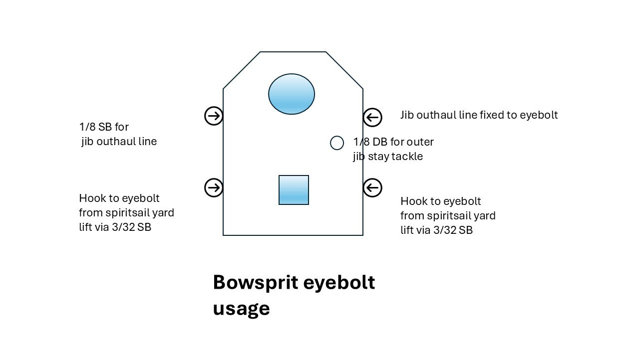
I am working on another project currently (USCG Harriet Lane). But, I did finish the chainplate that attaches to the hull (see photo). I made a jig with nails on a piece of scrap plywood. I used 22 and 28 annealed wire to make the links, fastening each carefully as I made the chain. I then fabricated the'plate' from styrene strip which I painted black. All this will be cleaned up and attached when the masts are in place. I will add a final coat of black at that point. Moving on to masts and yards, I discovered quickly that ME did not provide the proper diameter dowels. The ones found on the parts list were all present in the kit box (although three had a nasty warp), but they were not correctly labeled and not in sufficient lengths (based on the dimensions found on sheet 4). I need to purchase 1@3/32, 2@1/8, 1@1/4, and 1@3/8. No one seems to manufacture or sell 3/32, so I will substitute with 1/8 for the spanker mast. I can source all locally for under $5.00, so I'm not going to request from ME. Small change: I found that the jib boom outhaul tackle does not have a home for the fall which comes off the starboard side of the bowsprit cap. I decided to fix it to the stbd cleat numbered #4, and run the fore royal stay backrope fall to the unused cleat #4 on the port side of the inboard bowsprit. Attached for reference is a simple chart of the five attachments to the bowsprit cap facing aft (i.e. from the bow):
-
Thanks to both of you for the 'heads up'. The Niagara suffers from almost the same problem, but in that case there are 18 guns to adjust. I found this out too late to correct properly, so some of my guns would destroy the bulkhead in real life...
-
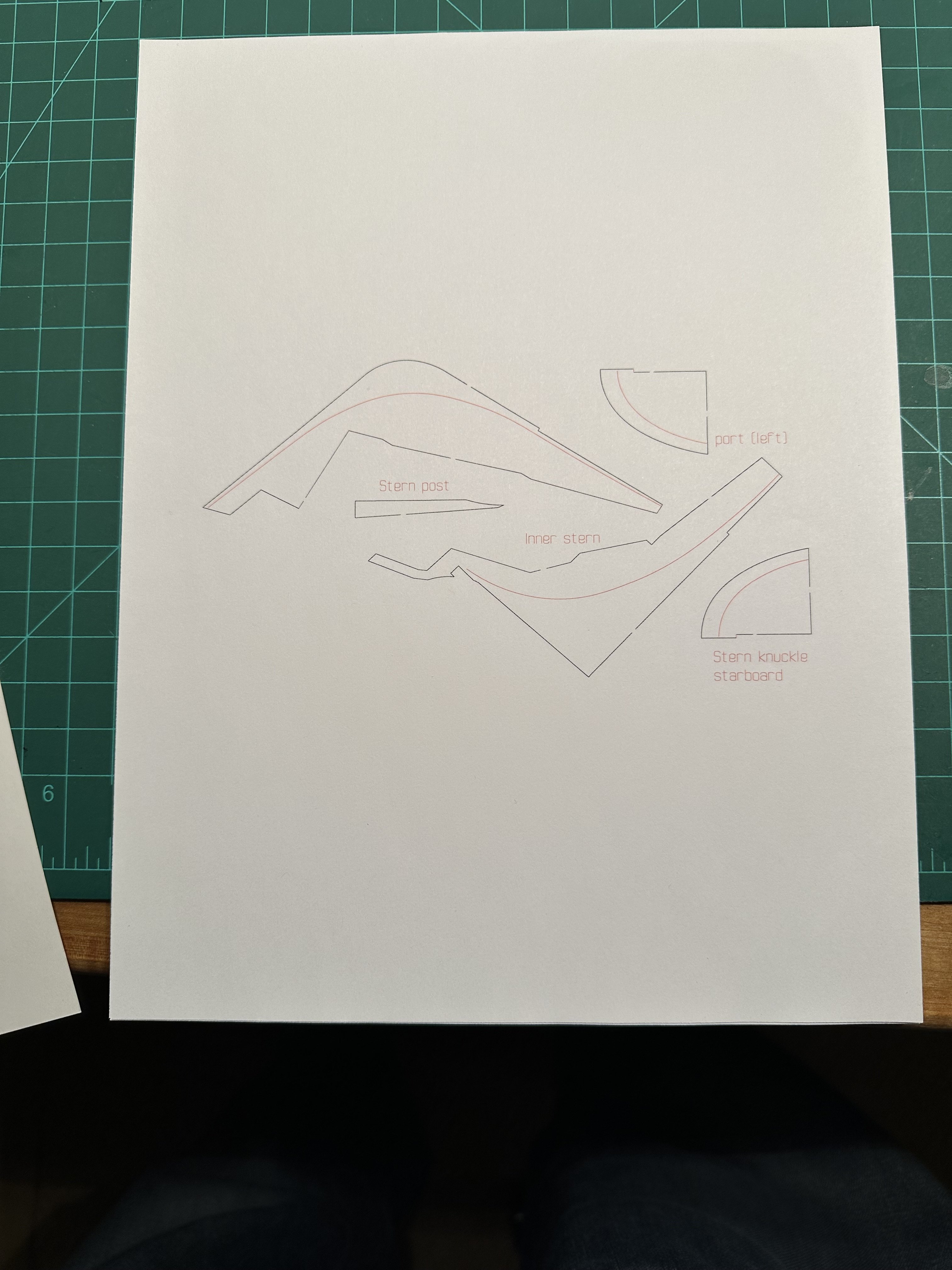
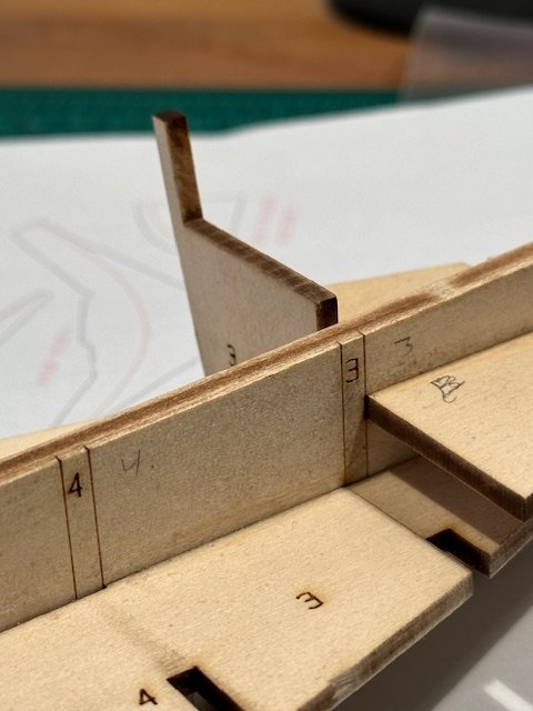
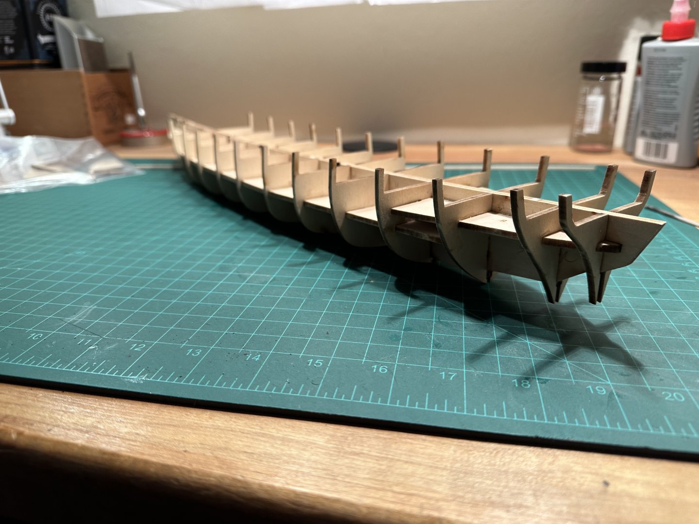
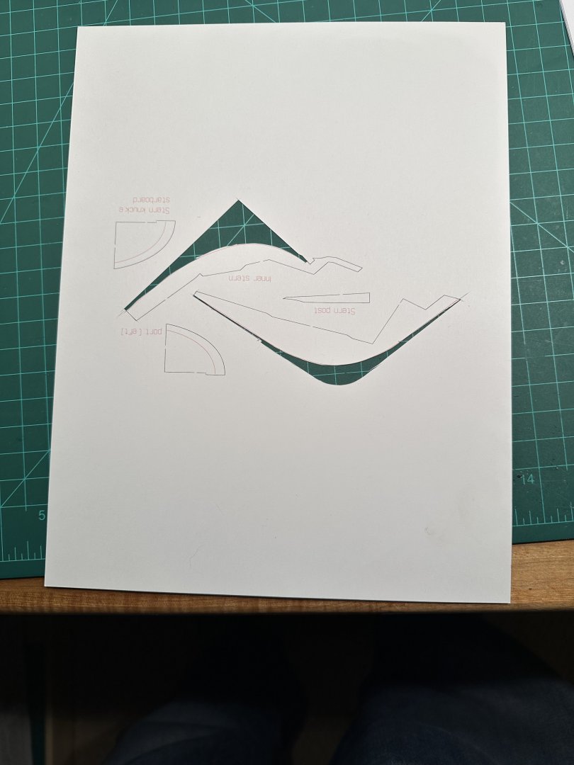
So far this has been a relaxing build. All kit parts seem to be high quality, although making masts and yards from soft and fragile basswood may not be a good idea. I think I will use some spare dowel material for those components. Initial work involved separating and cleaning up various frame and bulwark pieces from basswood billets 1-4. This went very quickly and easily. The layout of components attempted to follow the grain of the wood as much as possible, all burns were complete, and components separated easily with a #11 blade. A sanding stick was used to remove char, and glueing proceeded almost without incident through steps 1-2. EXCEPT for bulwark 3! Apparently kits assembled prior to June, 2024 had a couple of problems: bulwark 3 P&S had a notch about 1/8 inch too low, resulting in the bulwark sticking up above deck level. See photo below. I contacted Model Expo, and they have shipped me a new billet with the modified bulwark 3. All the rest of the 15 port and starboard bulkheads fit exactly perfect. Only minimal sanding (basically the wedge created by the laser burn) was needed for an easy fit of the interlocking pieces. I was impressed with the extremely accurate laser results and the guidelines on the wood. I proceeded to install all pairs from bulkhead 4-15, and made 1-2 ready to drop in. I used angle irons to ensure each bulkhead was 90 degrees to the spine. I then went ahead to prepare the inner stem and stern posts, step 3. The text refers to 'curved lines' printed on the wood for guidance in shaping the rabbet at the bow and stern - essentially the defining the area to be tapered from 1/8 inch to 1/16. These lines did not exist on my billets. Having read on the forum that others had encountered this problem which was resolved by Model Shipways, I contacted them and received a .jpg via email which I printed off on my color printer set to approximately the correct scale (117% in the case of my Canon printer). A little trial and error was needed. The text suggests transferring to the back side of the wood with tracing paper, but it was much simpler to just cut out a stencil from the printed sheet and trace the borders onto both sides of the components. See photos. So, that's as far as I have completed until I get the replacement 'bulwark 3'. I guess I go back to fabricating yards for the Niagara until then. Oh well...

-
I am taking a needed break from my Niagara build (getting bogged down in the minutia), and I decided to build the Harriet Lane, one of the first Coast Guard ships ordered by the US government. She was built in 1857, and I felt her to be an interesting change from building period sailing vessels, what with her dual propulsion - sail and steam. The kit was designed by David Antscherl. It is well documented with an instruction manual containing numerous color photos. It is listed as an advanced build by Model Expo, but I would call it more of an intermediate build (Niagara or the Constitution being an advanced build). I ordered and received the kit very quickly. It was packed well within another box, but the shipment had been damaged by the postal service (one end of the box was bashed in) which resulted in the etched brass sheet being damaged. ME replaced this sheet after I used their replacement form, and it arrived within a few days. I verified all parts were present (giving me the chance to become familiar with them), and I skimmed through the manual as well. I will start the build experience in my next post, as the dinner bell just rang...
-
Been a while since I posted, but NRG sells a plaque stating "Taint a hobby if you gotta hurry". And I would add - lot's of time spent waiting for paint or glue to dry. I was making chainplate, but got frustrated - so I set the components aside for now. I planned to proceed with shaping the lower masts, but after 2 miserable trys with round dowels, I decided to get some square stock and proceed from there. It's easy to taper the round dowels, but hard to place the octagonal section and attachment pin at the base in proper alignment with the square section at the crosstrees. I acquired some 3/8 square cherry strip, and I will return to this after the weather warms up (my power tools are in my unheated garage). Having read many comments on when to attach bowsprit (before or after rigging), I decided to 'attach and then rig'. I am working inside out and bottom up more or less. So far so good.... I attached the bowsprit to which I had previously added various fixed features such as steps and , after removing the 2 cleats which prevented easy installation through the precut hole (wish I read some older comments from people who found this problem), and then added the bowsprit cap/dolphin striker, jib boom and flying jib. All had necessary holes, eyebolts, and and dumb sheaves preshaped. I added lashings as appropriate. The initial lines I attached were the heavy bobstays. I completed as many lines as possible without the foremast installed. I decided to leave the spiritsail yard off for now as I felt it's web of braces would complicate attachment of the stays and guys to follow. I will add it when the other bow rigging is complete. (NOTE to future builders - don't forget the 5th. eyebolt placed on the front of the bowsprit cap. It doesn't appear on most drawings.) Whether the spiritsail existed on the original ship is an interesting question. It provides a great deal of lateral support to the bowsprit/jib sticks, but it clearly could not be used for actual sail power - too many fixed lines running below the bowsprit wouild interfere with it's set. And, then there is the question of the jib boom outhaul - where, oh where does it run??? If anyone has photos of it, or plans to visit the ship next year, please check this out and let us know. In modern terms, an outhaul (and downhaul) are used to control shape of a sail attached to a given yard/boom, particularly in strong winds. These can be used to give a sail more belly or to flatten the shape depending on the ship's relative heading to the wind. I'm not sure they cared about such niceties in 1812, but I am installing it and running the line to the rail somewhere.

-
milosmail reacted to a post in a topic:
Spritsail yards on Niagara and Constitution
-
Spritsail yards on Niagara and Constitution
milosmail replied to gak1965's topic in Masting, rigging and sails
I was pleased to find this question posted as it puzzled me. It seems the answer would be "no sail was set on the Niagara's spiritsail yard". Rather it is there to provide lateral support for the jib boom and flying jib boom. So, maybe the foot ropes were not needed to attend these standing fixed lines?? I am just rigging this piece of the ship, and I came to realize no sail would fit below the spiritsail yard due to the presence of so many stays, etc. Some research showed that if sail was set on other ships, it was farther out on the bowsprit or jib boom, well forward of the dolphin striker. -
I have seen questions from others in your thread dealing with lines that seem to have no attachment points. Some running rigging (that which is used to control sail position) may not have an attachment point to any fixed object other than maybe a cleat, but rather would be directly attached to a sail. I have only studied the lines forward of the foremast so far, and many are of this nature. So, what to do with them? Modern day solution is to tie them (loosly) to any convenient point where they will not be in the way. An unused cleat would be appropriate as well. This may also apply to downhauls, outhauls, buntlines and other lines that control the shape of the sail in various wind conditions. So, in these cases, there is no 'correct' point of attachment, if no sails are present.
-
Steve, your rigging is outstanding! I'm about to start by shaping mast components (having completed and attached the bowsprit), so I will follow your work with great detail. Jason, one caution with the Niagara plans. They include all the lines needed for control when the sails are set (sheets, guys, some downhauls, etc.). These lines attach more or less directly to the sails. Your Fair American probably does not include these. Most historic ship models do not include them. In my experience, the sail control lines (not to be confused with lines controlling the yards) - at least with modern boats, in which I raced - would not be left in place. These are normally taken down to avoid unnecessarly weathering and chafing. The kit accurately represents the Niagara as it appears today, including all the lines needed for sail control. Net - probably don't add any lines if not shown on the Fair American plans. But it's your call.