HOLIDAY DONATION DRIVE - SUPPORT MSW - DO YOUR PART TO KEEP THIS GREAT FORUM GOING! (Only 20 donations so far - C'mon guys!)
×

alross2
-
Posts
409 -
Joined
-
Last visited
Content Type
Profiles
Forums
Gallery
Events
Everything posted by alross2
-
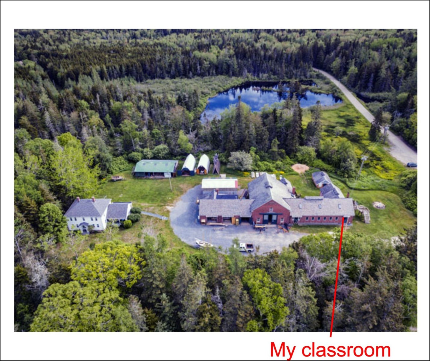
 No more posts for a week or so. I'm teaching at the WoodenBoat School from Sunday to Friday next week. Love that place!
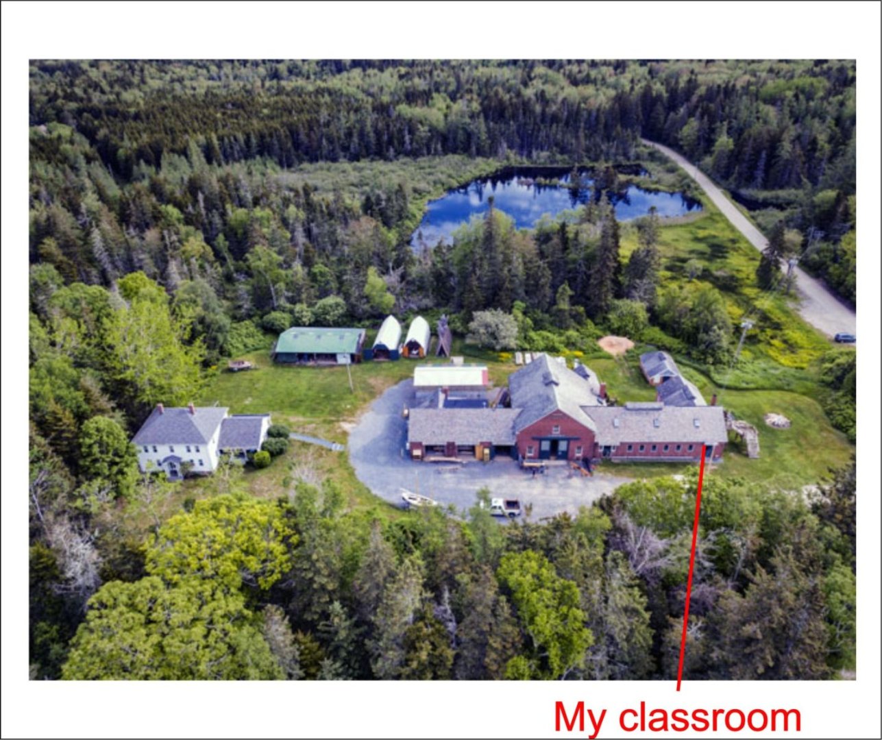
- 194 replies
-
- 10
-

-

-
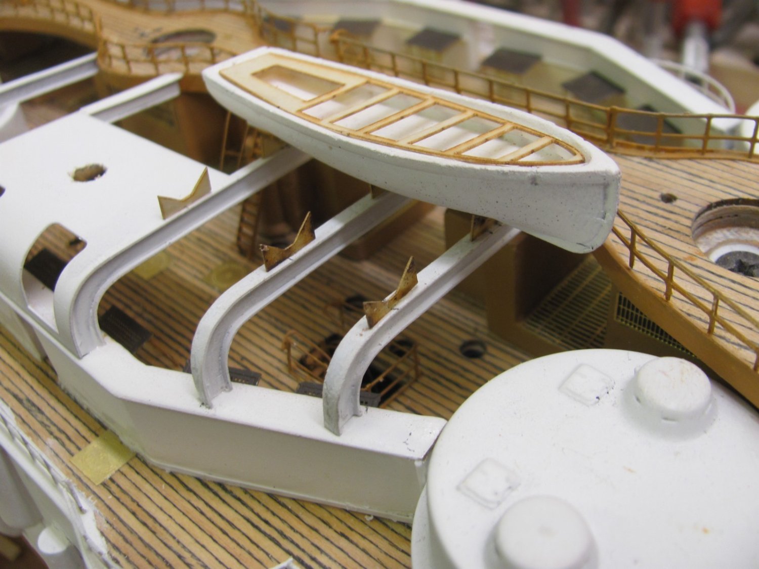
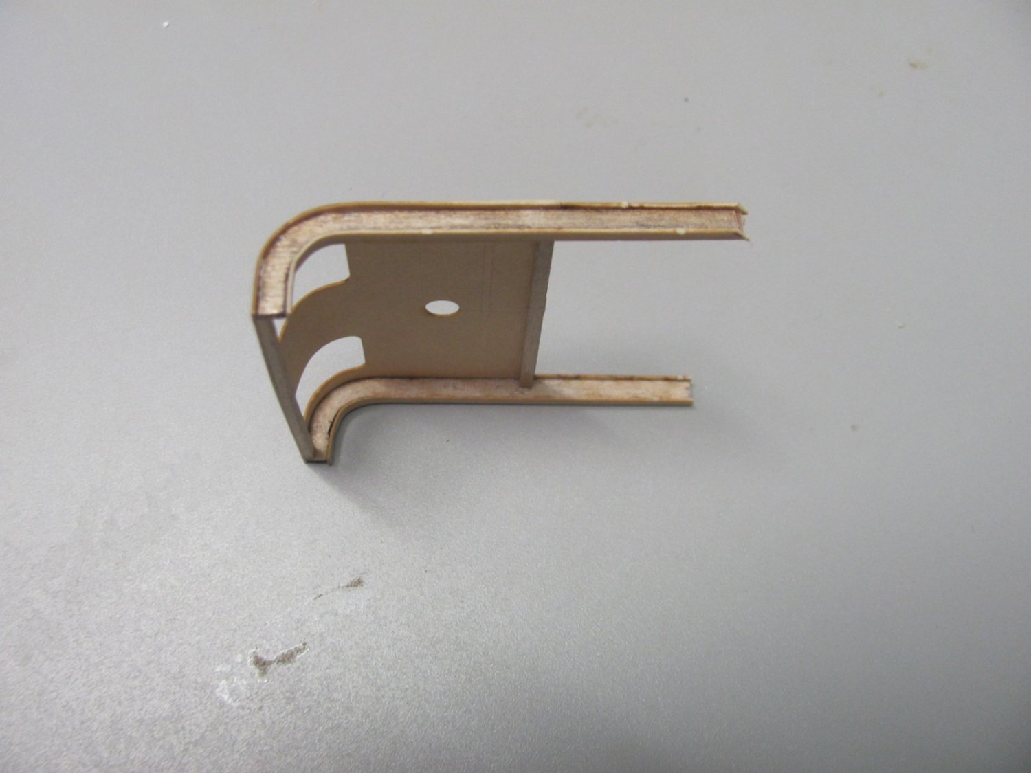
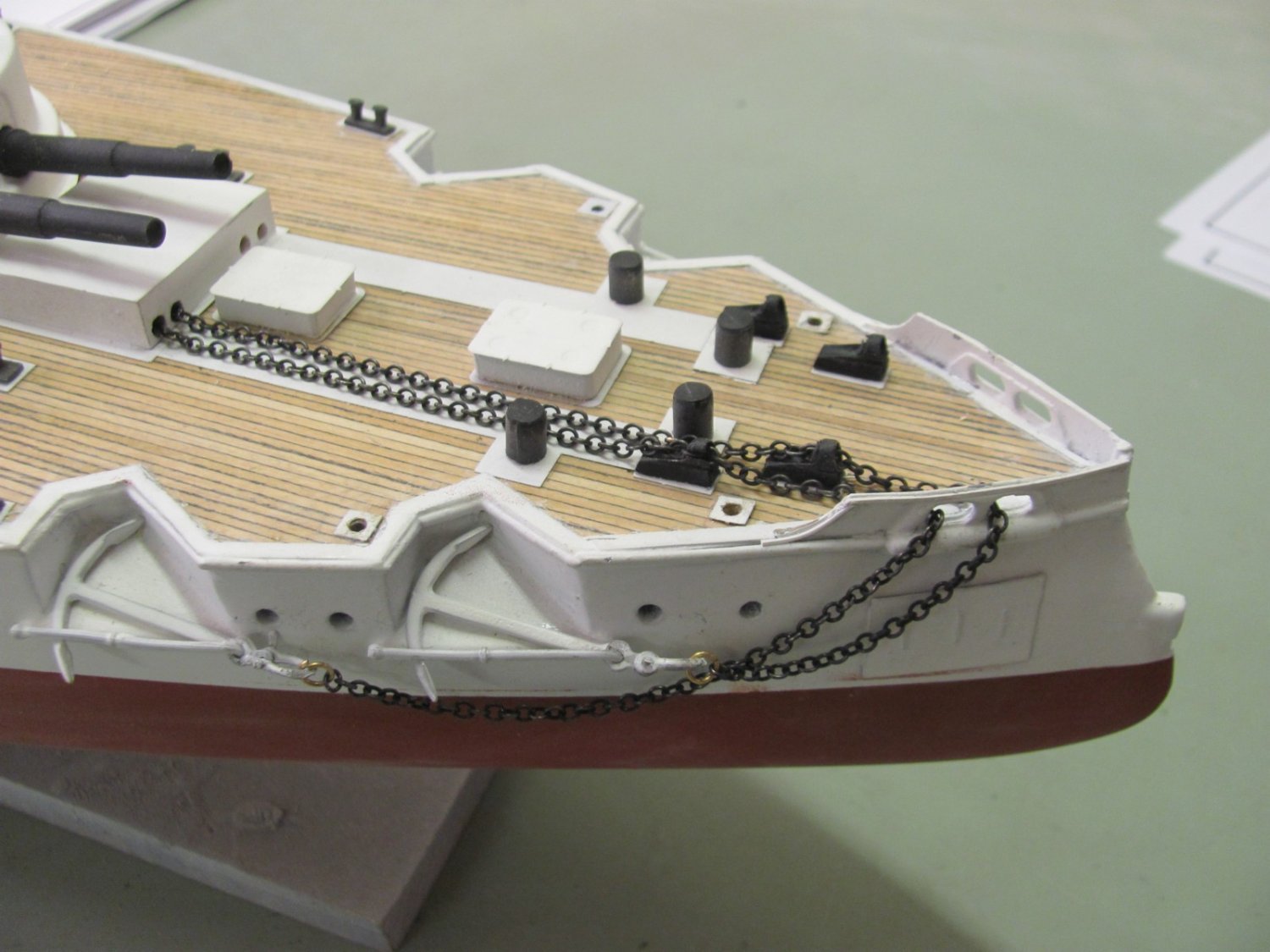
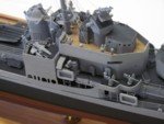
Brackets for the boat davits and the starboard boat skids are on. The unfinished boat crane is just sitting in place. The brackets are .035" laser board. I really like this stuff as it is exceptionally strong for its size and cuts extremely well.


- 194 replies
-
- 14
-
-
-
All of the lower stanchions are rigged and the awning stanchions on the port side have been installed and rigged. The pin on the bottom of the awning stanchion fits into a hole drilled in the hull, so they are quite rigid when fitted.


- 194 replies
-
- 10
-
-
Ran the starboard lifelines today. It reminded me why I hate to rig...

-
Railings and inclined ladders for the superstructure deck have been installed on the port side.

- 194 replies
-
- 12
-
-
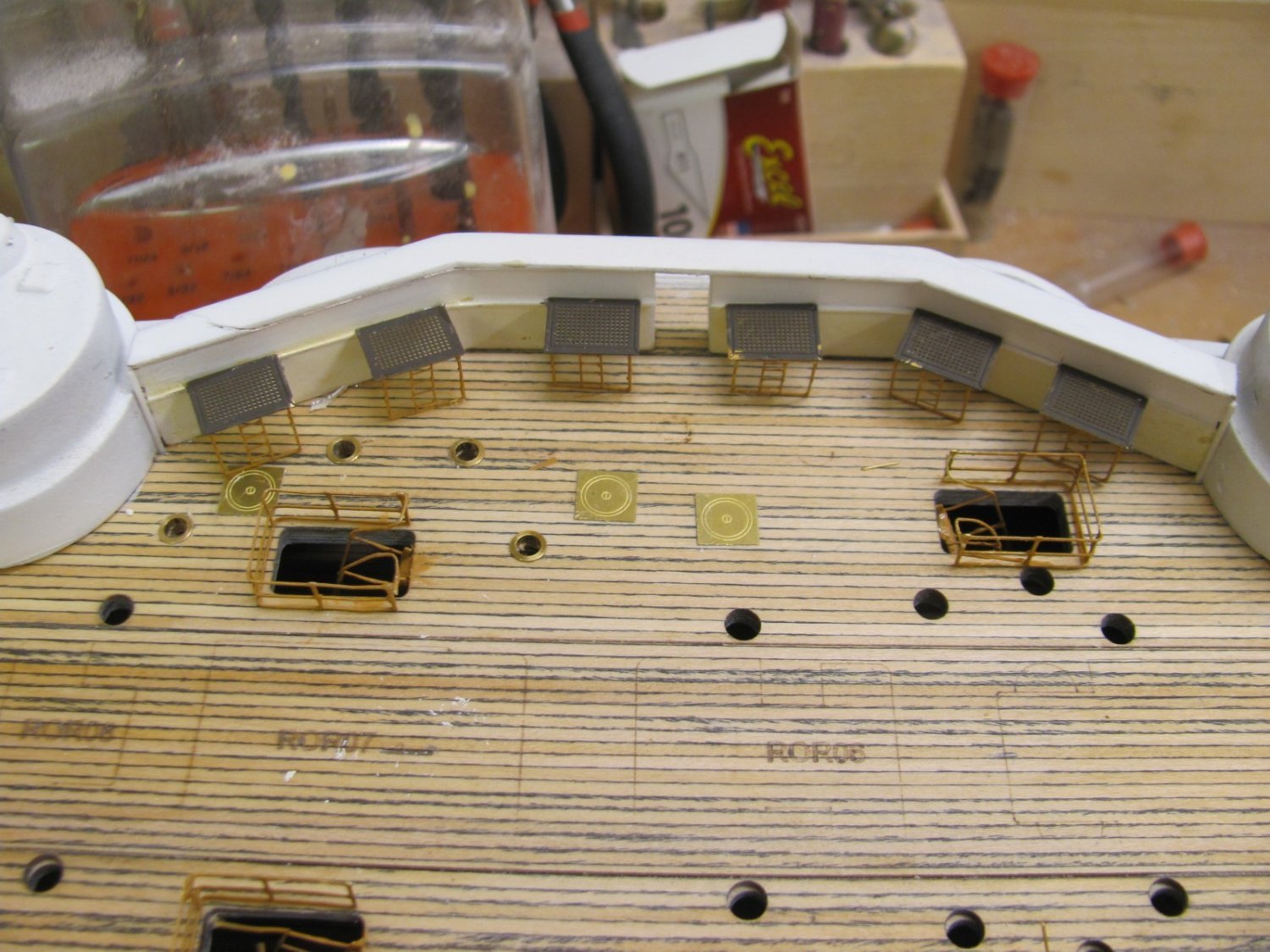
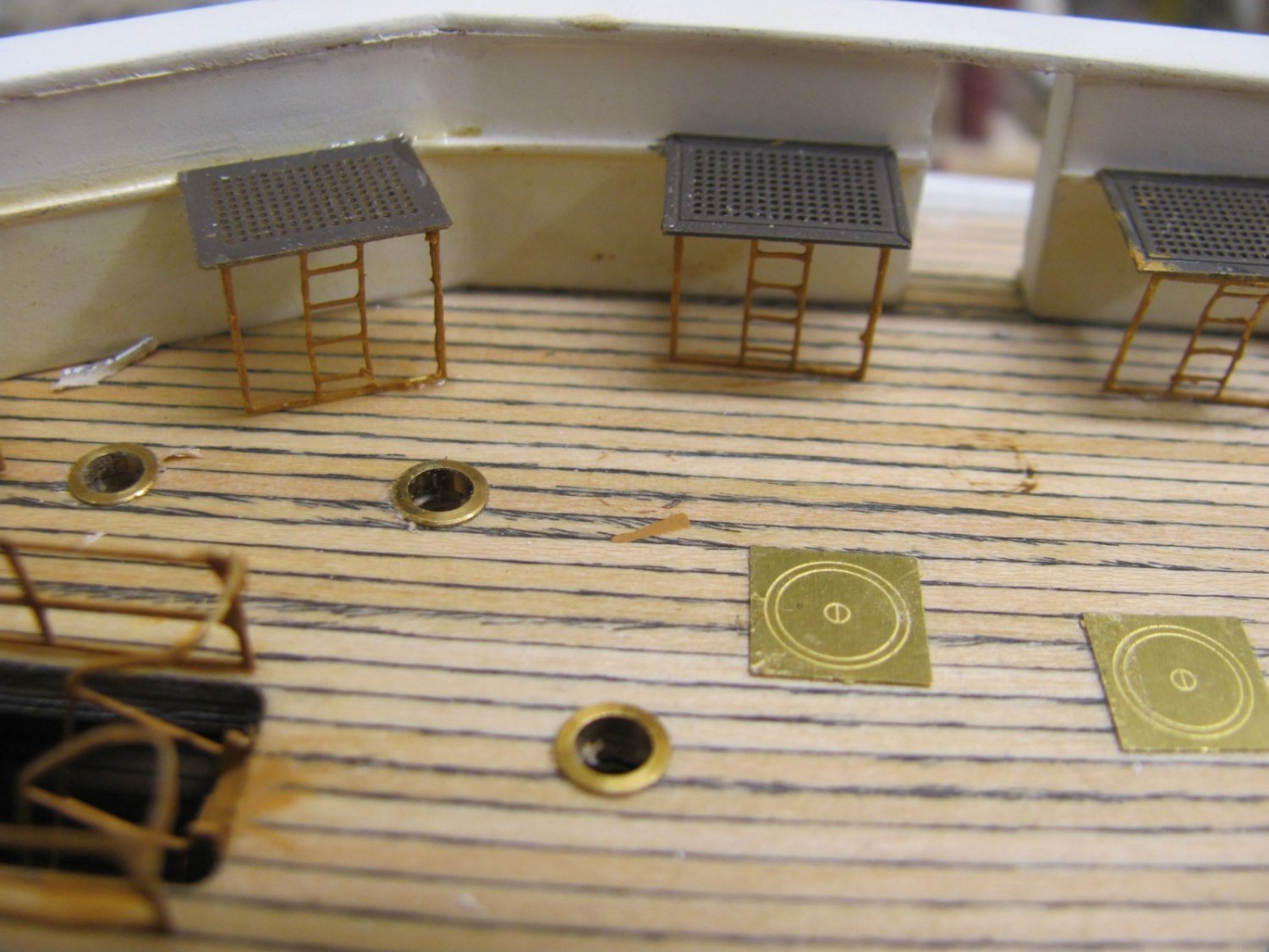
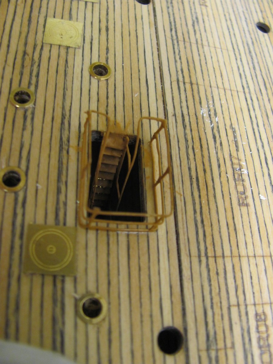
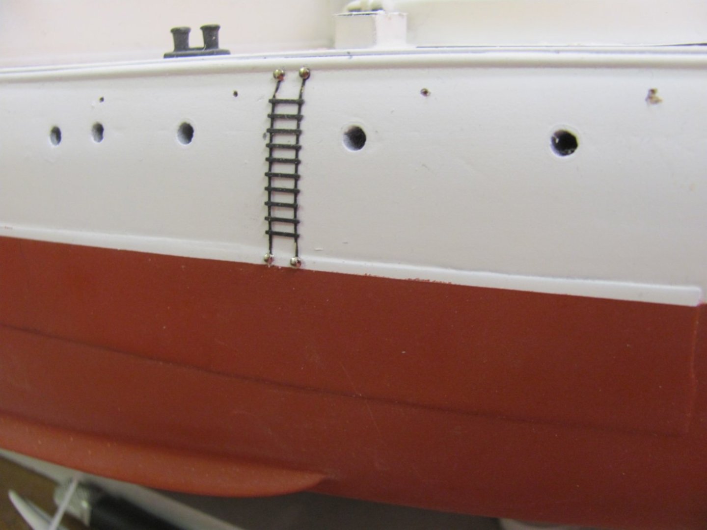
Photoetched Jacob's ladders and life ring cages attached. Everything is touched up at the end.

- 194 replies
-
- 11
-
-
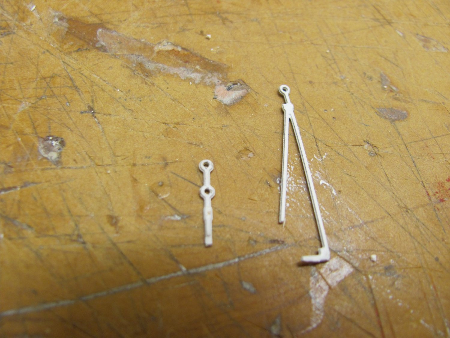
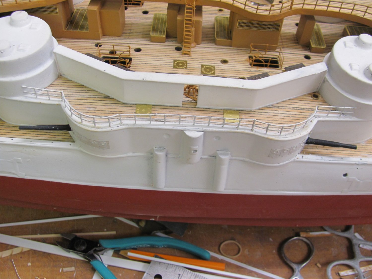
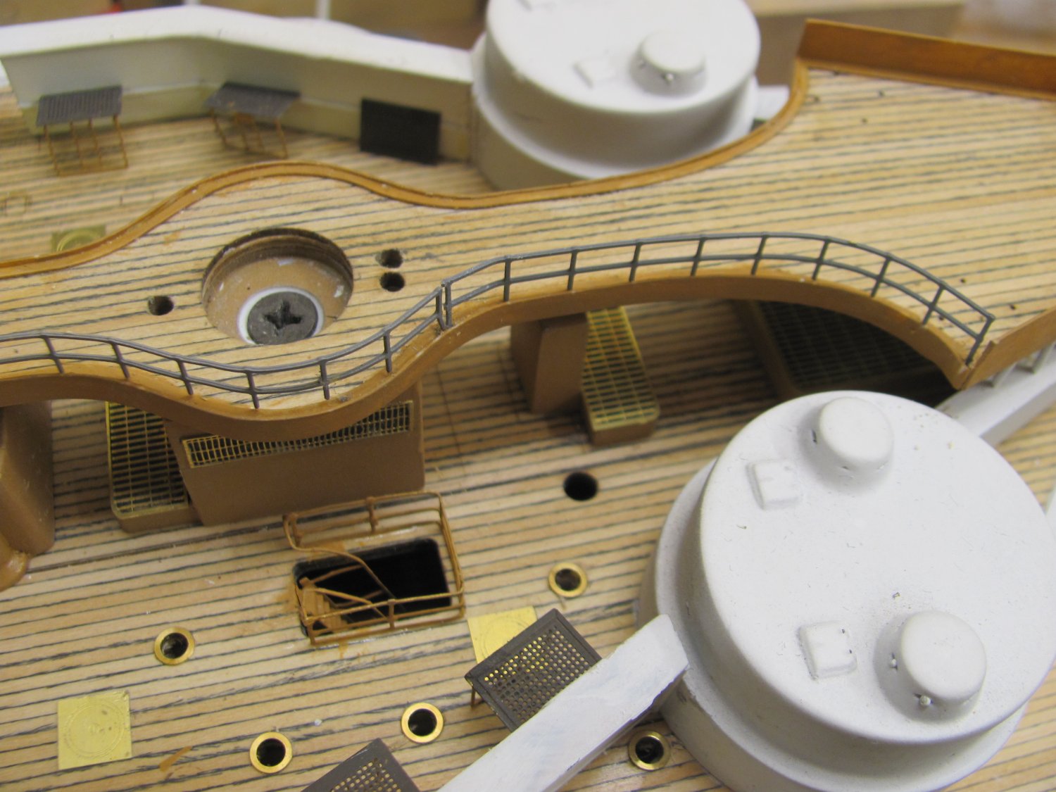
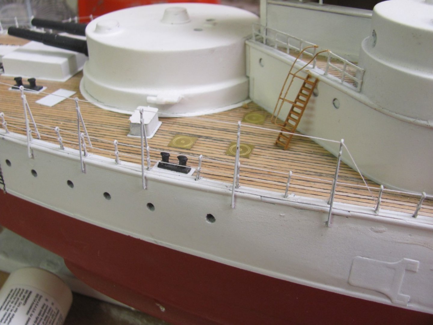
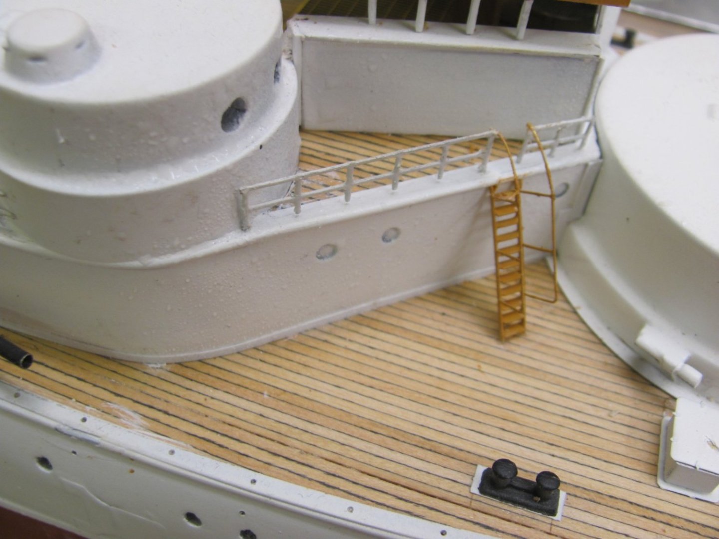
Test fitting the photoetched railings to the hurricane deck. There are four pieces per side and they are designed to fit in specific locations. This will require some careful bending and fitting to get them right. The end stanchions are a bit longer than the rest, so locating holes have to be drilled in the deck. An inclined ladder fits in the opening.


- 194 replies
-
- 11
-
-
-
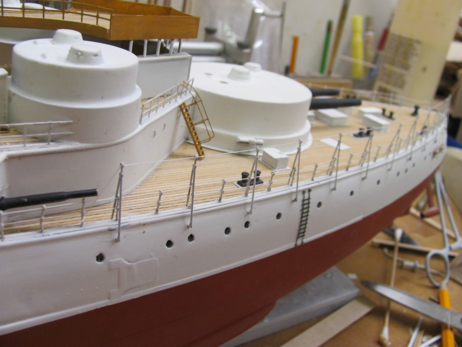
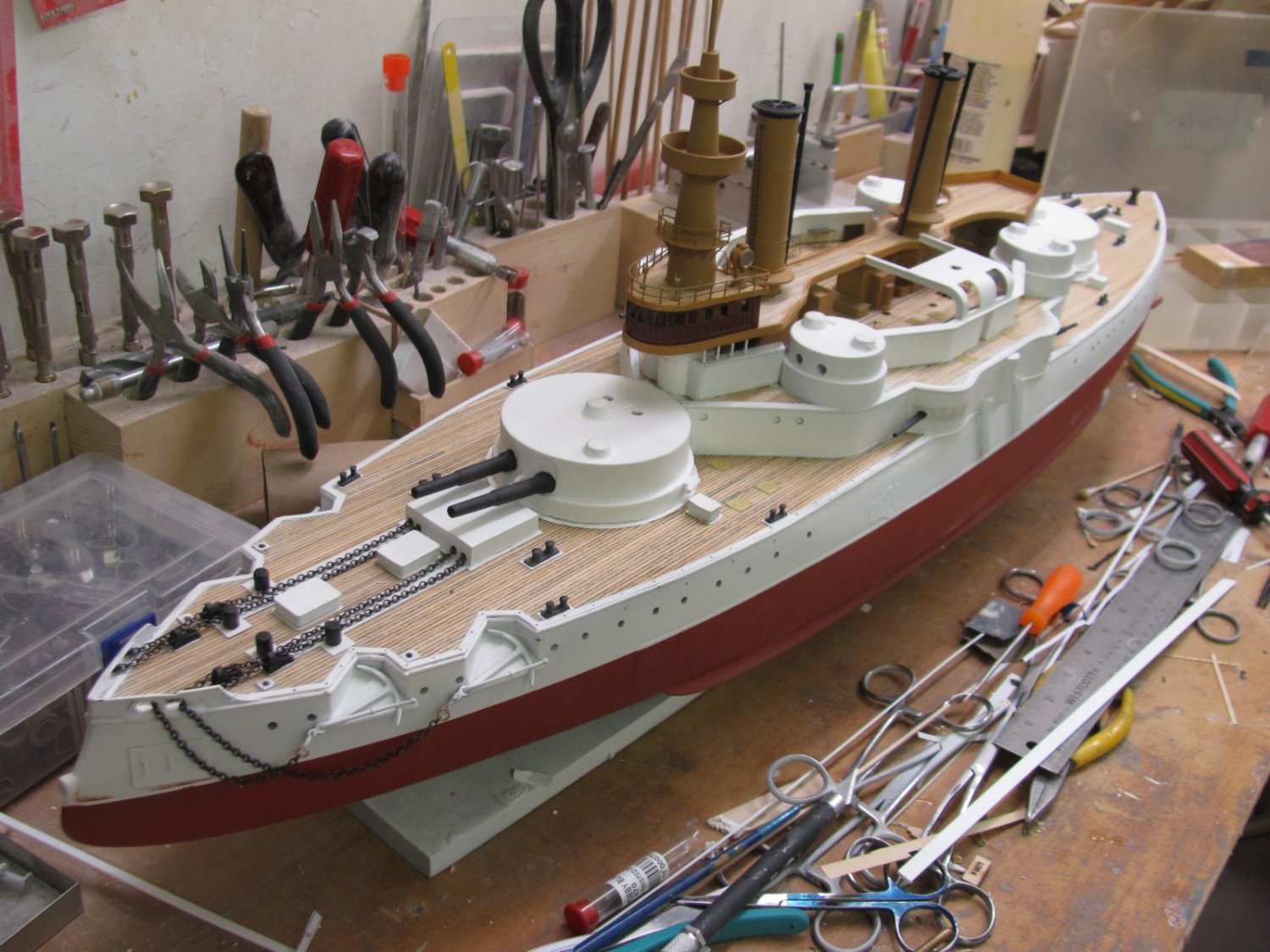
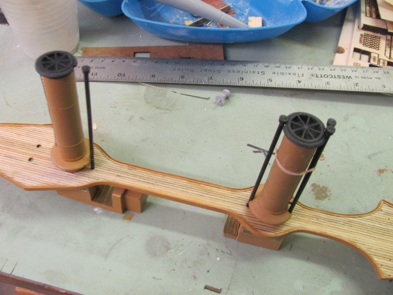
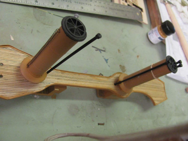
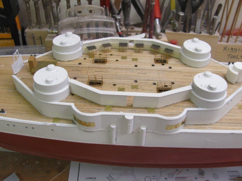
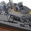
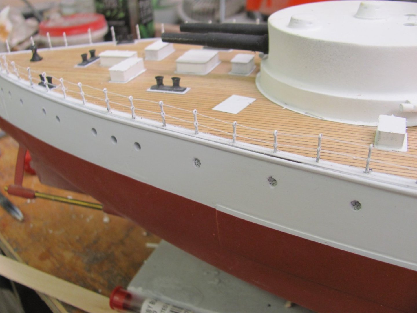
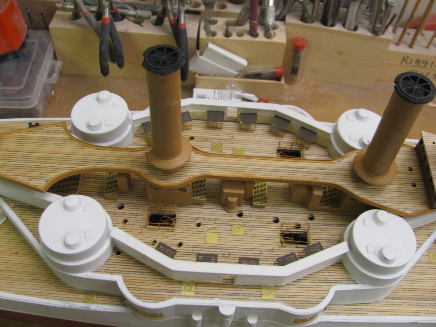
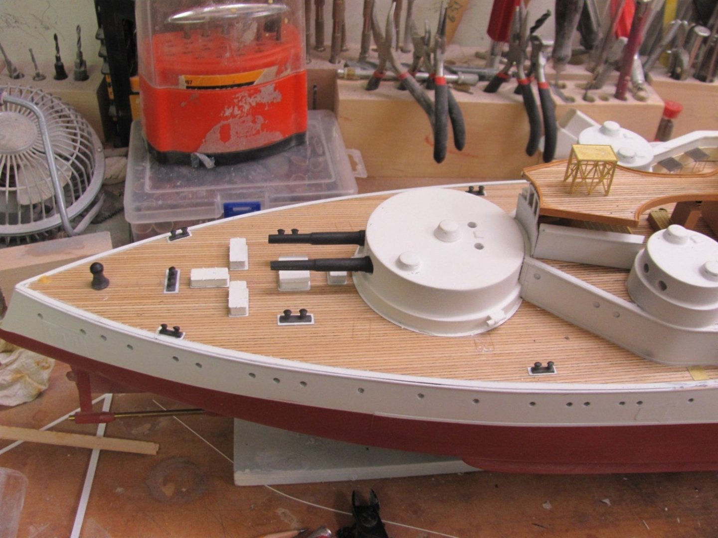
6" gun barrels and all hatches glued in place. Stacks, pipes, and center boat skids are just sitting there for fit assessment. Getting there...


- 194 replies
-
- 10
-
-
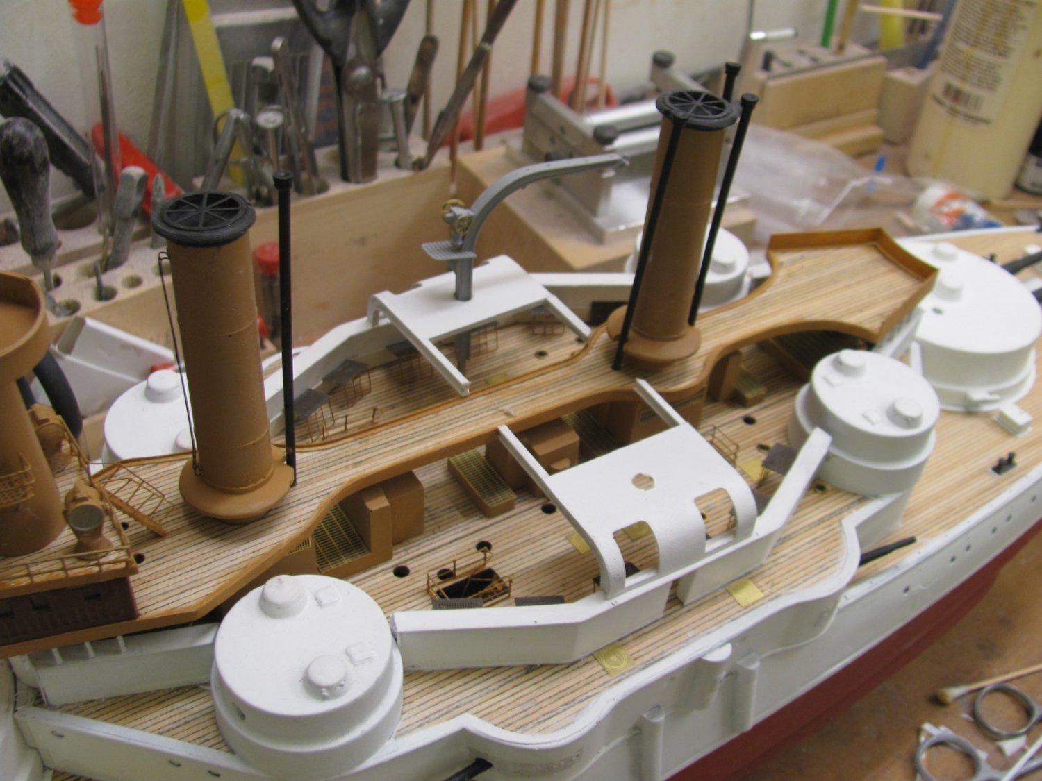
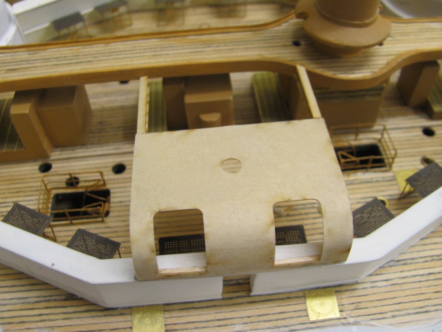
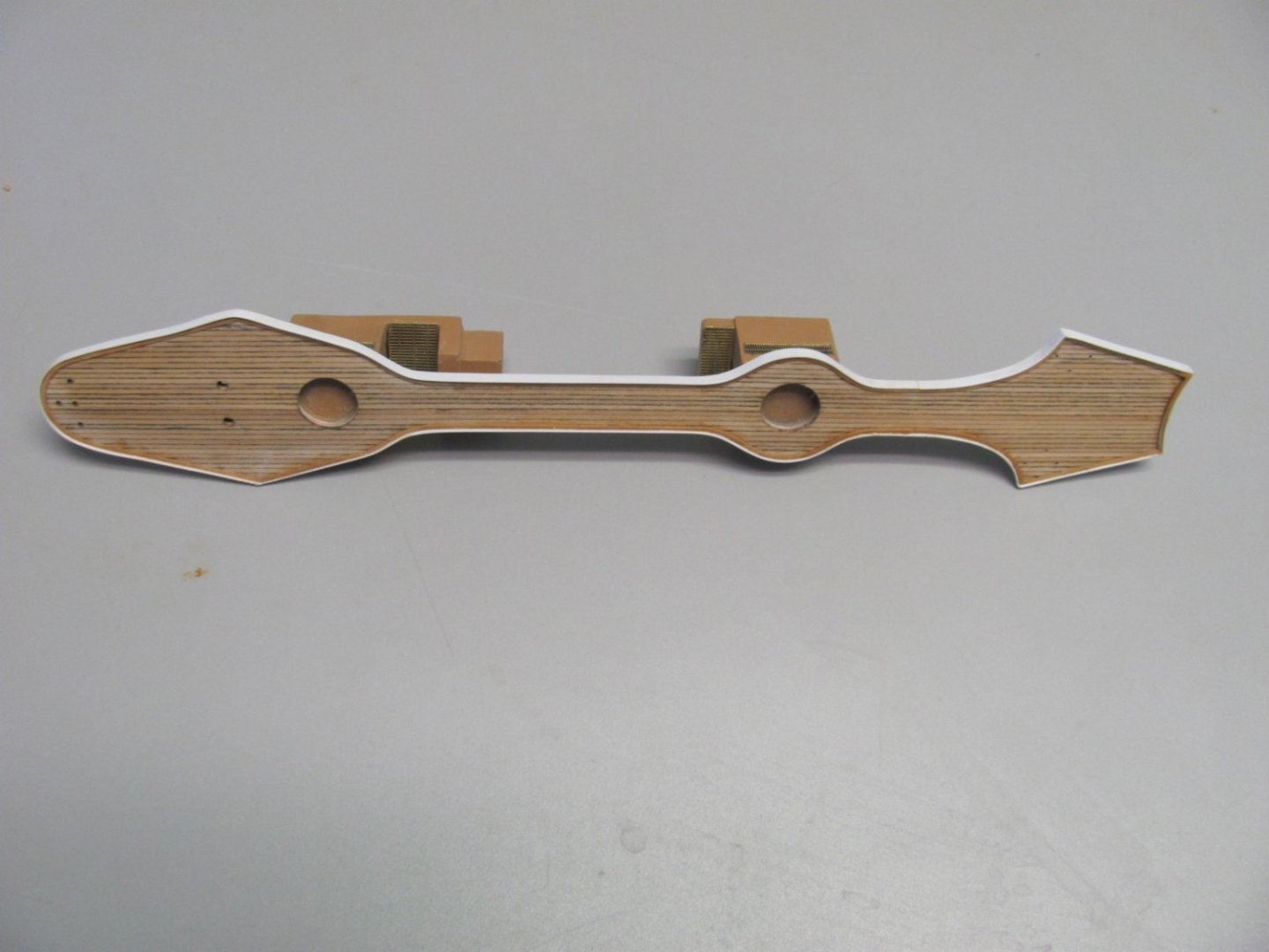
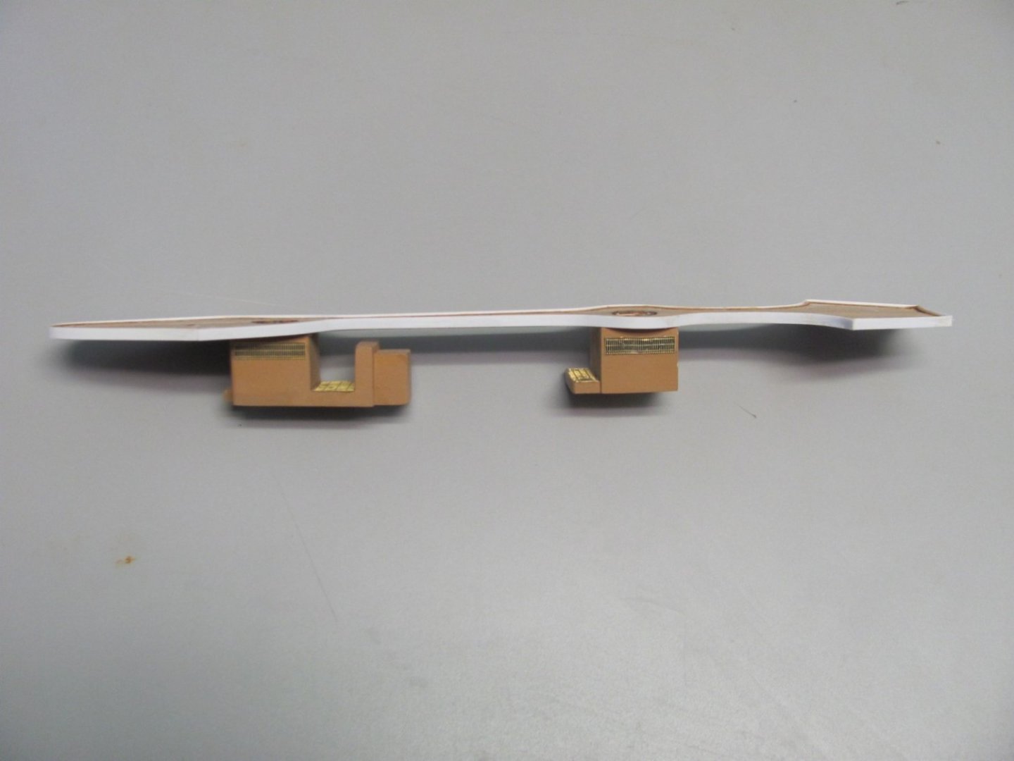
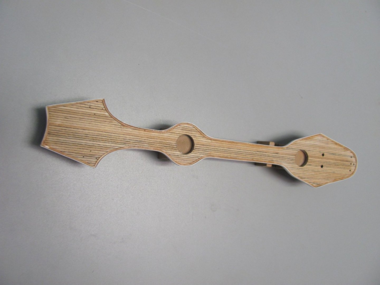
Center boat skids and shelter roof. There are 9 pieces to each one as the skids are built up with a web and two flanges. The boat crane goes through the hole.

- 194 replies
-
- 12
-
-
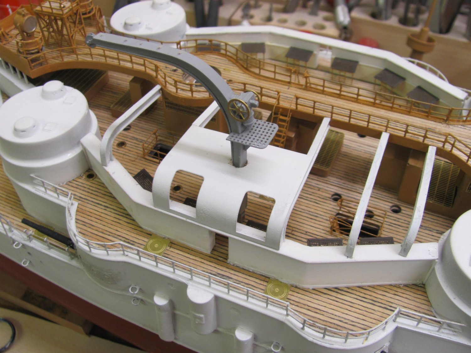
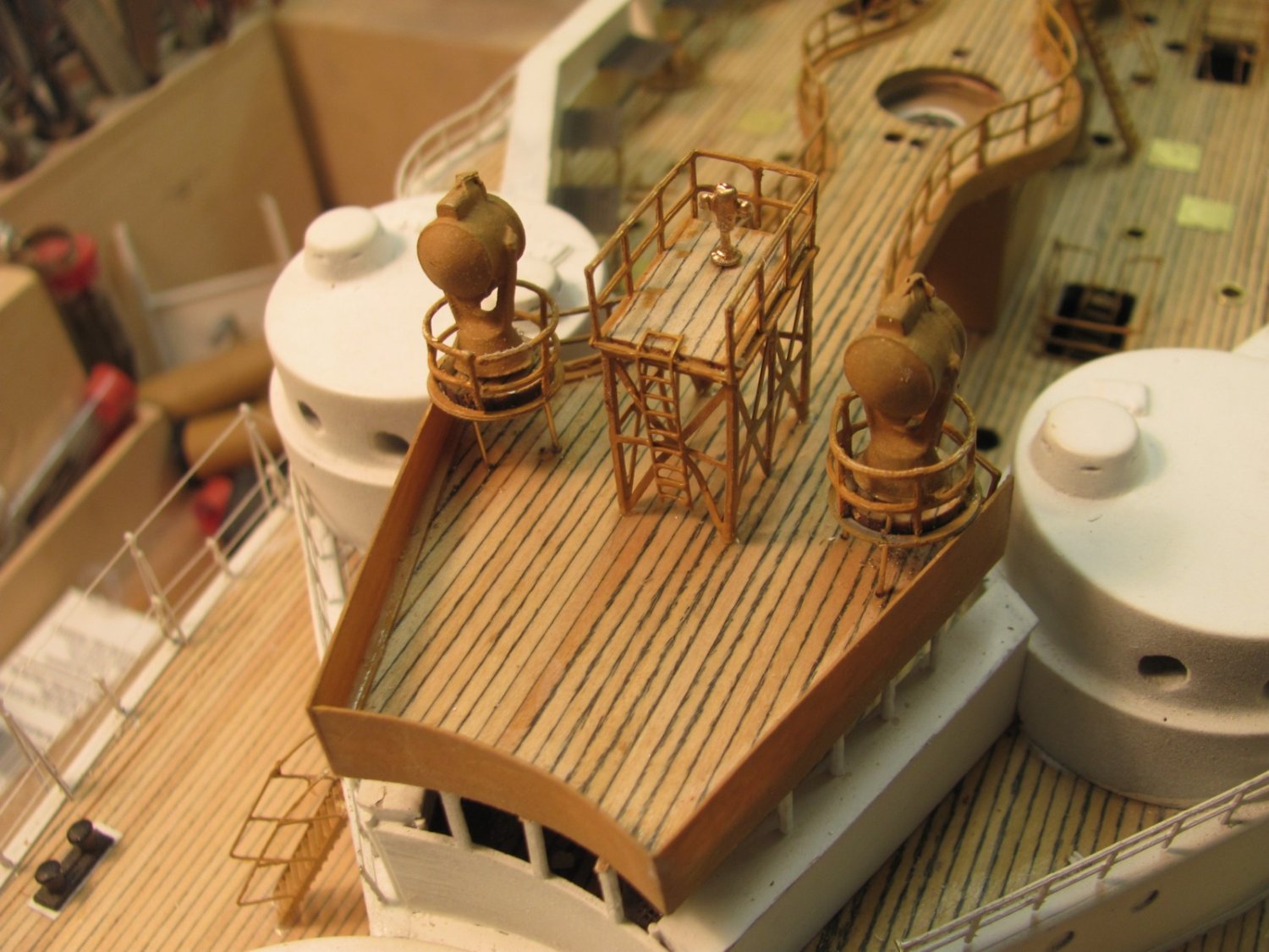
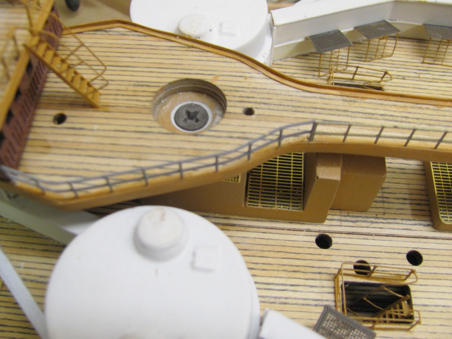
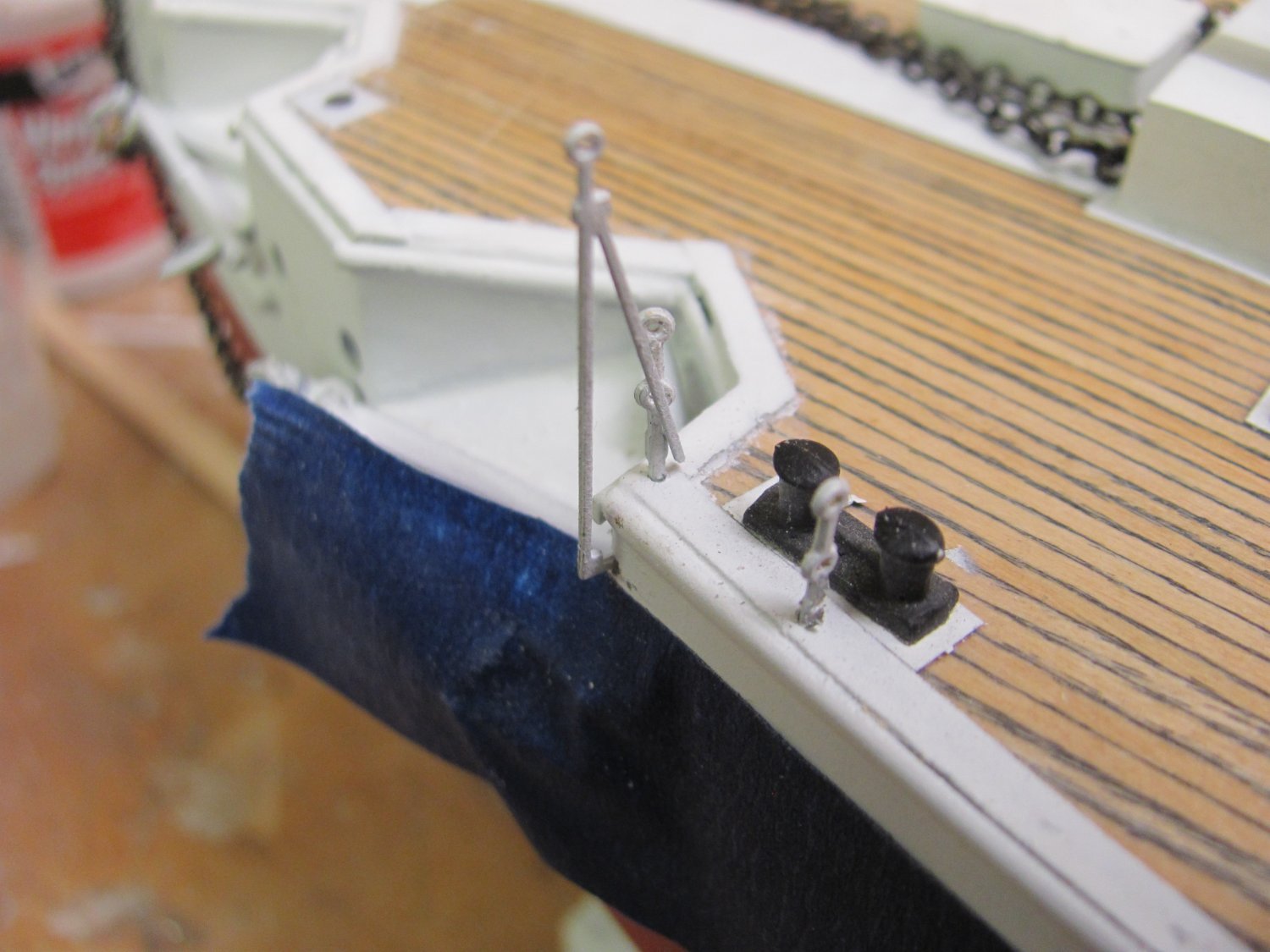
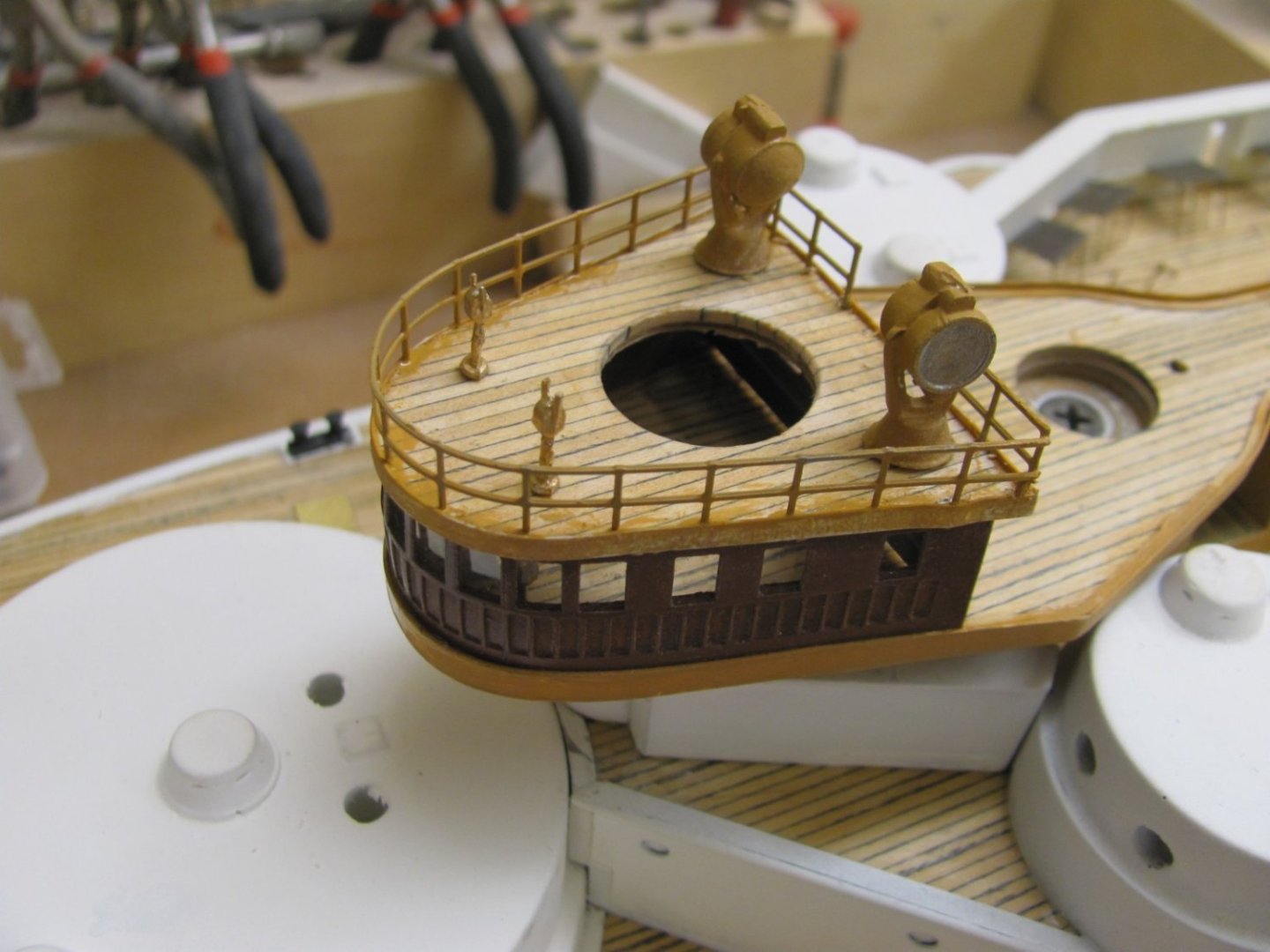
Pilot house is now on, rails, telegraphs, and searchlights fitted. The two holes aft of the house are for cowl vents and an inclined ladder will go from the deck to the pilot house roof.
- 194 replies
-
- 10
-
-
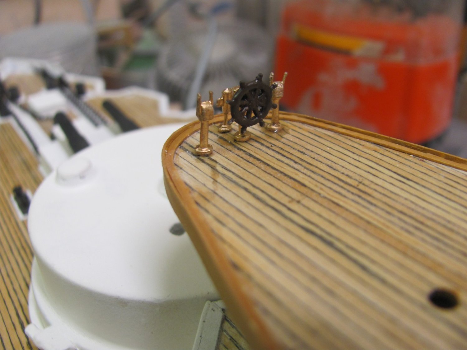
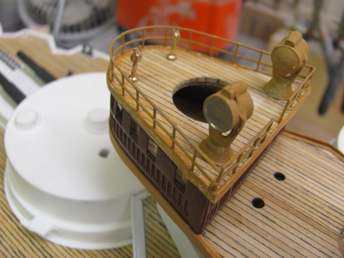
Pilot house steering station in place. The pilot house will have clear windows but you'll relly hsve to look closely if you want to see them.

-
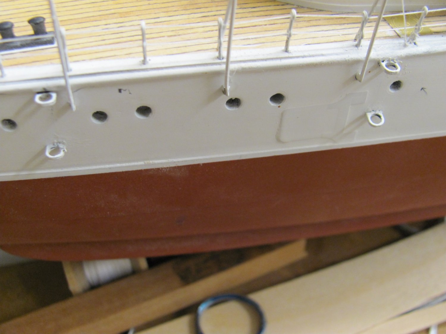
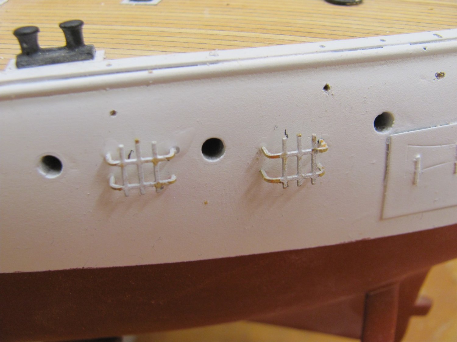
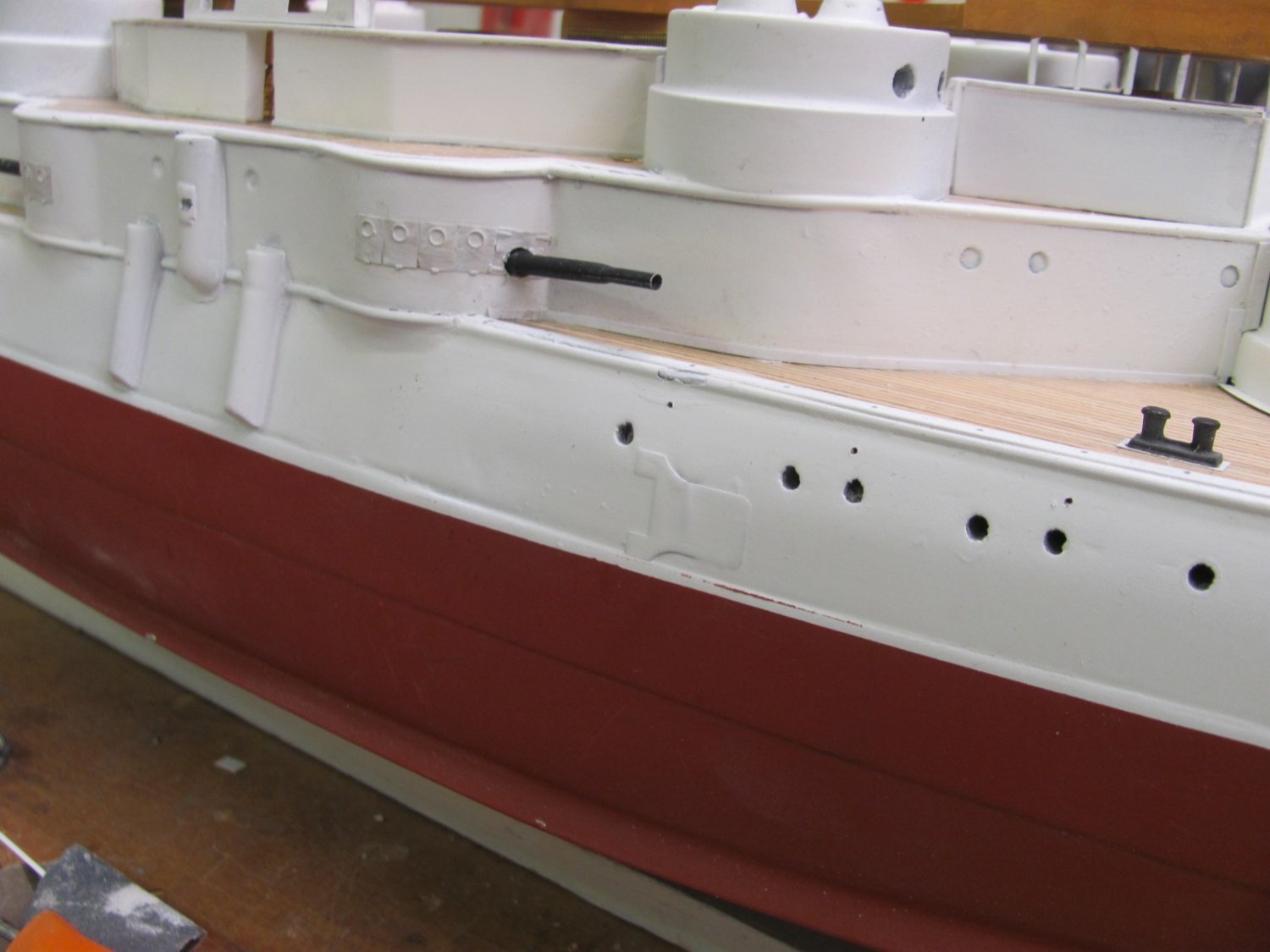
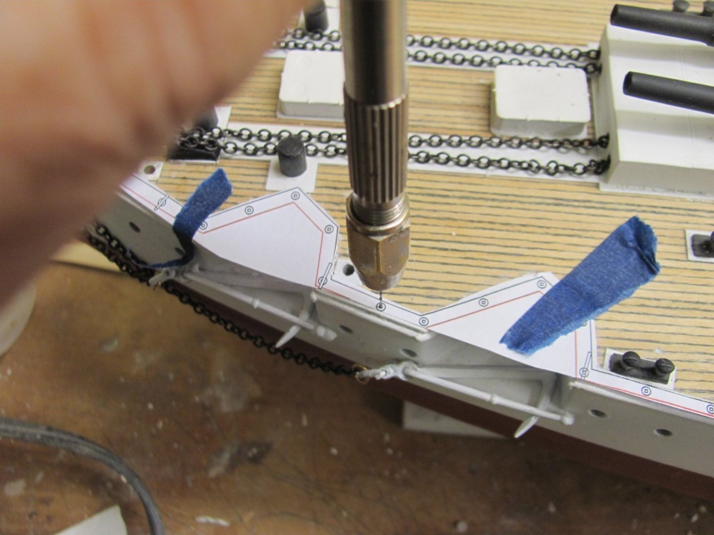
Once the holes for the main deck stanchions are drilled, the holes in the side of the hull for the awning stanchions are drilled. The blue tape ensures that they are all at the same level below the deck. Their locations are marked on the template. Both types of stanchion have a mechanical stop on their bottoms to ensure they are at the same height.

- 194 replies
-
- 12
-
-
Using the kit-supplied template to drill the main deck stanchion holes.
-
Strangely, I absolutely loved his Richard Bolitho novels but couldn't even get through one of his MTB ones! Since I focus on this type of vessel, you'd think it would be the opposite. Maybe I should try to read one of the MTB novels again.
-
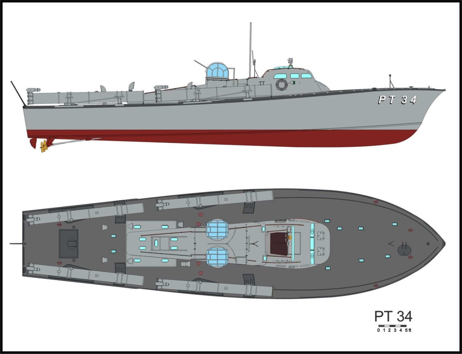
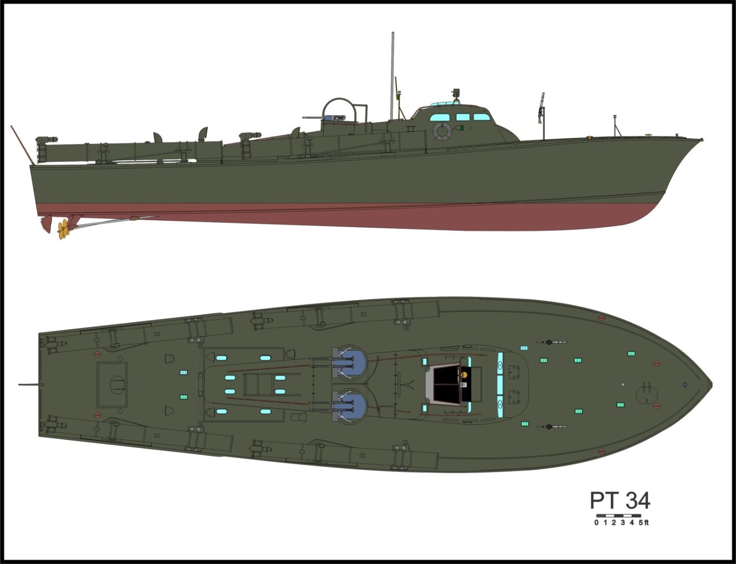
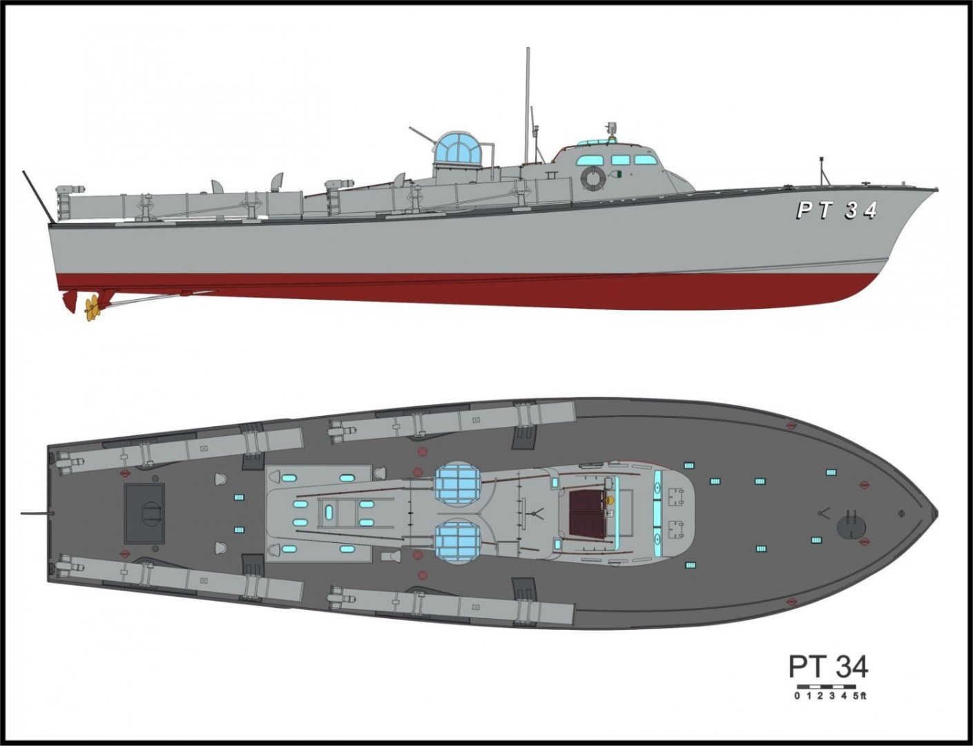
What would have been PT52 was also a 77' ELCO. It was built for the RN as MTB310 and was lost at Tobruk in 1942. The 80' ELCOs depicted by the kit ran from 103-196.
-
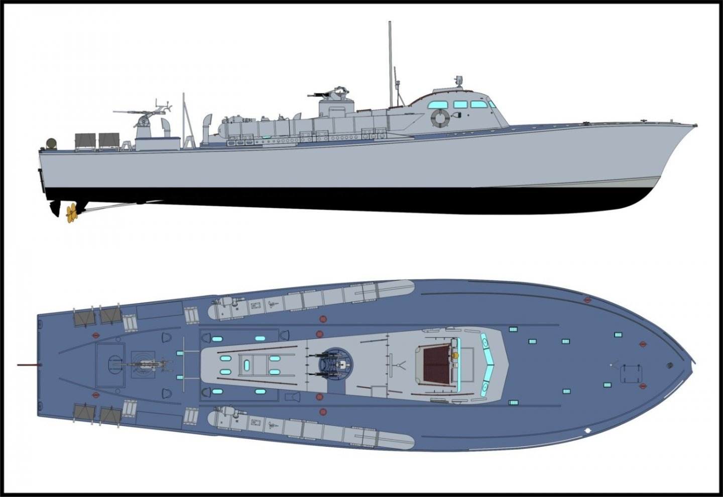
The RON3 boat were 77' ELCOs; this is an 80' ELCO. In the movie, they used two 80s and four Huckins boats, none of which looked like a 77'. Here are two renderings of what they would have looked like. The gray image is as they left the factory in Bayonne. Once the war began, they removed the domed covers on the turrets and painted the boats green. My Dad was the quartermaster on PT34 at the time. She was lost on 9APR42 and he was captured a few days later, spending the rest of the war as a Japanese POW.

-
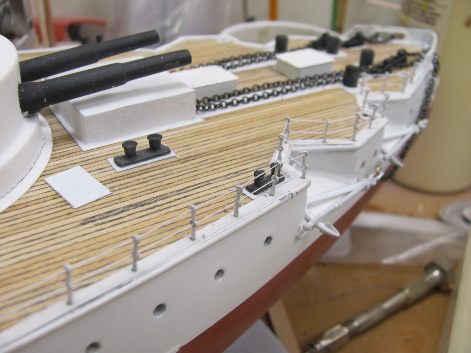
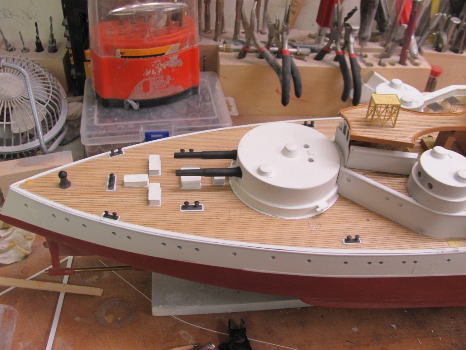
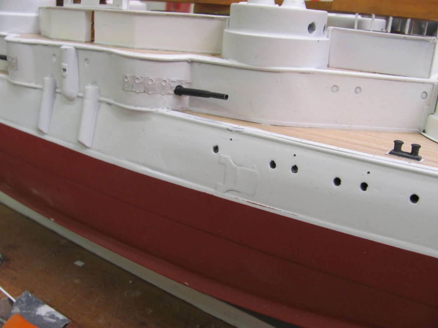
Another "make sure it fits before you glue it down" check. I do this several times a day when developing kits so I can make the necessary adjustment to the laser parts prior to finalizing. There are at least 200 more parts to put on before she's done.

- 194 replies
-
- 13
-
-
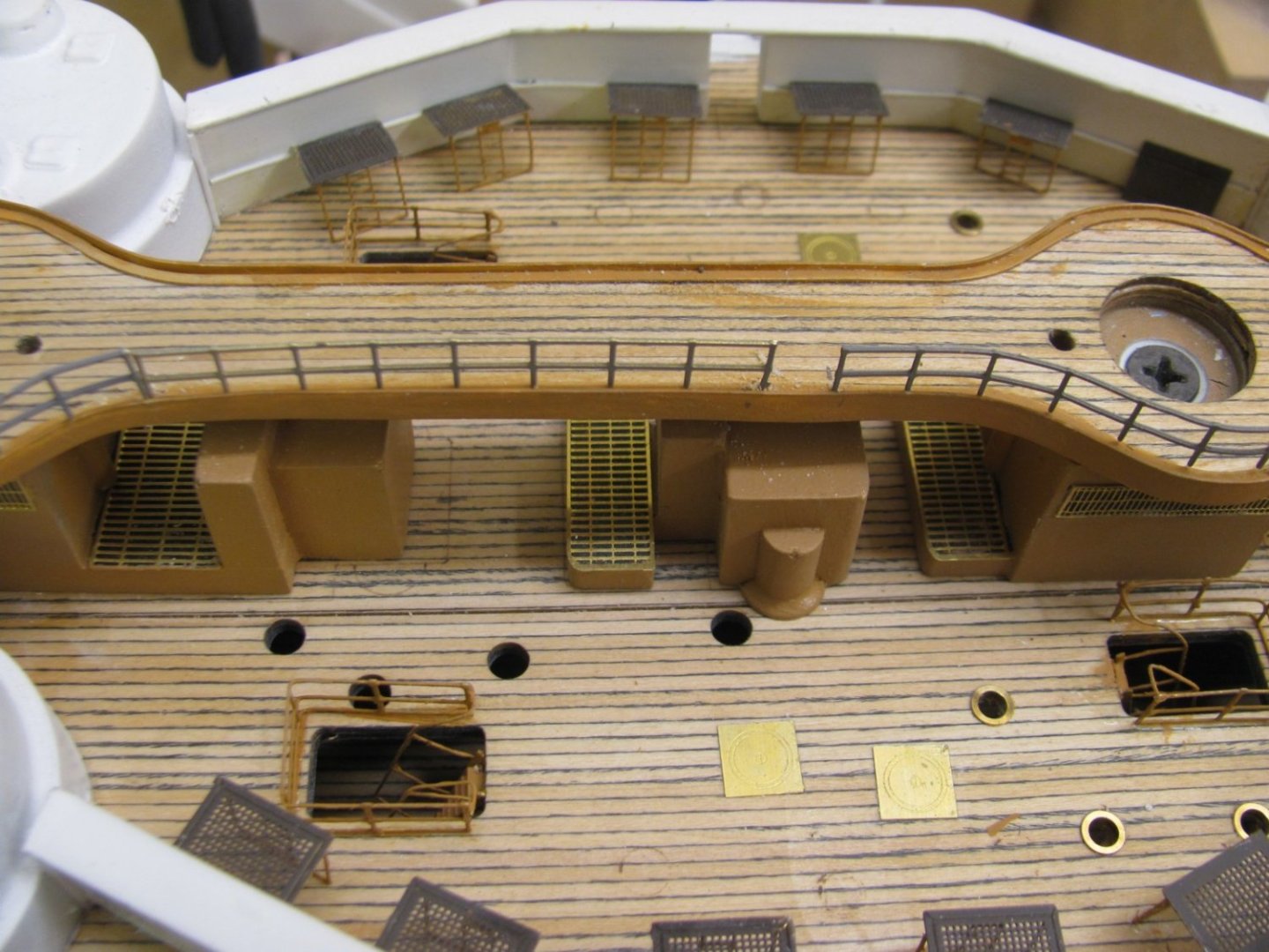
.015" x .156" styrene edging has been applied to the hurricane deck and will be painted buff shortly. The hammock structures have been painted white and are drying at the moment.
- 194 replies
-
- 11
-