

mij
-
Posts
224 -
Joined
-
Last visited
Reputation Activity
-

 mij reacted to shipmodel in Queen Anne's Revenge 1710 by shipmodel - FINISHED - 1/36 scale
Hi again, and best wishes for a happy Friday the 13th –
Thanks for the compliments, likes, and wishes for my new grandson. Caleb and his mother are both doing well and send their thanks as well.
Several smaller items were completed in this segment. The first was the forward bulkhead for the captain’s cabin. There are no plans or drawings of it in either of the plans that I am using, so I designed it to be functional, using some of the same details as on the stern and quarter badges.
There is a chair rail molding with wainscoting below. This was not scribed but laid up from individual planks. The door is of a typical 17th Century style, with H-L hinges and decorative cross banding. The windows are flanked by fluted columns which were built up as before. To each side there will be a ladder to the poop deck, which have not yet been constructed. The bulkhead is still removable at this stage, and may have to be moved back a little to give me room to install the whipstaff which will go between the cabin and the mizzen mast.
I have not decided whether to paint the wainscoting blue and add some decorative details. What does the group think?
The cabin was also dressed up by closing in the aftmost gunport with a decorative shutter. The central circle was made by stiffening a 1/8” birch dowel with a drop of thin cyano on its cut end. When dry the center of the dowel was drilled out to a depth of about ¼” and then the circles were parted off on the table saw.
Next I turned to the first of the rigging fixtures – the staghorns. Here is a section of my plans for the inner bulwarks, which was made by using PhotoShop to combine the plans from the Advice Prize with details from Le Mercure. You can see three of the four staghorns that will be mounted on each side.
Here is an enlargement of the plans for the staghorns. Note in the side view the extreme angles that have to be used to match the 13 degree tumblehome of the bulwarks.
I started by carving a length of pear to the shape of the horns of the fitting. The piece was just under 3 inches long, which gave me extra material for the next model as well. Here you can see three horns that have been parted off. They are a little heavy, but were later reduced with a small sanding drum.
The shelf that supports the horns was built up in two parts. In the larger, back piece, two notches were nibbled out for the horns before being closed in by the front piece. In the insert enlargement you can see how the curve of the table saw blade gave me an angle to the back of the notch that is needed to allow the horns to angle to match the tumblehome.
With the horns inserted in the shelf the bottom piece had two notches hollowed out in its back face for the lower ends of the horns.
The lower piece was flipped over and the horns glued into the notches. The lower piece was then sanded to its clamshell shape and the upper ends of the horns were refined to angle up and out. You can see the differences from the left fitting to the completed one on the right.
Here you can see a finished staghorn sitting on an angled scrap block to check that the shelf will be horizontal when mounted on the bulwark.
Here is the complete set of eight staghorns for the first model.
And here is the first one mounted in the waist ready for the lines that run through the hull sheaves for the main and spritsail sheets.
Next I turned to the gunport lids for the open gunports on the port side of the ship. I have detailed their construction before in the section on the test gun station. This one is for the forwardmost port, which is why the planking runs at an angle to match the hull planking. The hinge straps are blackened brass strip secured with three iron pins. The ends of the strips were ground to about half their width so they could fit into mounting holes in the hull.
The strips were all made to a uniform size in a simple jig. A brass strip was trapped between two guides and the locations of the holes for the mounting pins was marked off. Once the holes were drilled the strip was clipped to length at the edge of the jig. I found that without pre-drilling these holes it was nearly impossible for me to drill them cleanly once the hinge strap was mounted on the gunport lid.
Each lid was marked for its proper location and the mounting holes were drilled just above the open gunport. With the lids slid into the holes the brass could be gently bent so every lid was at the same angle. This will be a significant advantage once they are permanently mounted, as they will be much less prone to snapping off when I bump into them (which I am sure that I will). Here they are towards the bow - - -
And the stern.
To check them, I set the guns in place. Here is what they look like in the waist as seen from outboard - - -
And along the length of the ship.
Finally, the entire broadside.
I was happy with the look of the model, so the guns and gunport lids were removed to safe storage until the interior deck fittings are built and mounted.
The first of these was the riding bitts for the anchor cable. As you can see from the plans it incorporates the 5-sheave post for the rigging to the ramshead block that raises and lowers the foreyard.
Construction was straightforward, with each piece cut and shaped, then notched and pinned in place. The sheaves in the post are non-working, and made by drilling 5 pairs of holes through the post with a 0.040” drill in a miniature drill press. The bitt was then put into a Dremel and the sheave slot between the holes was carved out. Care has to be taken to allow for the right-hand torque of the bitt, but a little practice yields good results.
The next rigging fitting that I turned to were the multiple cleat ‘logs’ that sit just aft of the fore and main masts. These were discussed earlier in the build log as well.
Construction here was straightforward as well. Once the dimensions were decided, two pieces of cherry were cut and the ends finished with slopes. The underside of each was sanded to match the camber of the deck. Ten slots were cut in the underside for the lines to run through. It is quite probably that these slots would have been radiused on each side of the log so the line would run smoothly under the fixture. The upper corners of the log were eased as well, as recommended by JerseyCityFrankie. Matching photoetched brass cleats were obtained from Bluejacket, blackened and mounted.
Here is the one on the quarterdeck aft of the main mast. It looks good as is, although I clearly have to clean the deck which is getting very dusty.
Finally, to check that things are headed in the right direction, and to give my spirits a needed lift, I mounted the decks and the lower masts. Hull construction and detailing have taken much, much longer than anticipated, but I can see some light at the end of the tunnel. I just hope that it is not the oncoming train known as “RIGGING”.
Be well
Dan
-
mij reacted to Sjors in HMS Agamemnon by Sjors - FINISHED - Caldercraft/Jotika - 1:64
I don't do that Augie....
And thanks for the faith
But....pictures !
She is not finished but I wanna show you what I have done so far.
Sjors
-
mij reacted to Jack Panzeca in Oseberg Viking Ship by Jack P - FINISHED - Billing Boats - 1/25 Scale - 9th Century - (Modified)
H
Hi Von_Kossa,
Sorry about the oops! I have had my share of mistakes and re-dos, I just fix it and forget it as soon as possible.
I was not planning to use nails on the shields. I really like the look of your shields (post #23 and 25 of your log). What did you use for the center ornament?
The nail head diameter for the plank nails is 1.62 mm. They could be a little smaller but they really look good the way they are.
To blacken brass I use a product called Blacken It from Micro Mark. It is similar to the acid mix used to blacken guns. Take a look at this link http://modelshipworld.com/index.php/topic/1167-using-blacken-it/.
I got the spacing of the plank nails from two places. I have used two books and numerous internet locations to research the Oseberg. The books are:
I got 18 cm from the second book here and I got 8 inches (about 20 cm) from a web site. I was unable to find it again. I did a test to see if the 20 cm or if 40 cm looked better at this scale and the results are below.
Everyone who looked at the test agreed that the closer spacing looked best. I did increase the spacing from 8 mm to 10 mm just to compromise a little and save a few holes. The references in both the book and the website were not Oseberg specific but general to shipbuilding of the time and place. You may be right about the Oseberg.
Please let me know if I can help.
-
mij reacted to rcmdrvr in Willie L Bennett by rcmdrvr - FINISHED - Model Shipways - SMALL
Well, I am getting real close with the deck planking. Thanks to" russ" and "capt n bob"; the scraping process really worked well. Most if not all of the grey dust that was all over the deck has been removed. You do go thru quite a few single edge razors.
-
mij reacted to Remcohe in HMS Kingfisher 1770 by Remcohe - 1/48 - English 14-Gun Sloop - POF
So after lots of holes and filling them up again .....
The hull ready to be sanded
Close up of the end result
Remco
-
mij reacted to chris watton in Newsworthy updates from Chris Watton
Bellona will be released one day, I have no doubt. What I am saying it that it needs a re-design to make the hull assembly easier to assemble, and it needs to be stronger. As it is now, I have no doubt experienced model makers would have no trouble, but for the rest, it would be a nightmare for them (I can only imagine how many emails a day I would get forwarded by Amati from customers asking for help)! I just need to design out the fragility, and once that's done, it should be fine as the rest of the parts are fine.
Bellona was designed to try out new ways of building the hull with much more internal detail. from that experience I was able to design Victory with full internal detail. This was part of the point of Bellona - a test-bed for new ideas. If I still had to design the same old boring block-type models, instead of trying out new stuff, I would have gone mad with boredom by now!
-

 mij got a reaction from ccoyle in Xebec by mij - FINISHED - 1:60 scale
I used Bisley gun blue for the swivel guns
The model I started the beginning of January this year has now been completed.
The planking of the hull is Cherry and all the carvings are from Box.
Here are some photos of her
-
 mij got a reaction from GrandpaPhil in Xebec by mij - FINISHED - 1:60 scale
Milling the sides of the gun carriages
Drilling the holes for the 4mm blocks for the carriages
Turning a step suport
New carving of a rabbit
Model so far
-
mij got a reaction from GrandpaPhil in Xebec by mij - FINISHED - 1:60 scale
I was not happy with the carving of the first eagle, so I carved another one from Boxwood.
I cut out the shape of the eagle first, then started the carving.
I took Antony`s advice in putting a light stain on the carving to bring out the detail.
I used French polish and linseed oil.
Carving with the stain on.
Eagle fitted to the stern of the ship.
-
 mij got a reaction from Mike 41 in HMY Fubbs 1724 by Mike 41 - Scale 1:48 - second rebuild
Lovely work Mike
mij
-
mij reacted to Mike 41 in HMY Fubbs 1724 by Mike 41 - Scale 1:48 - second rebuild
You may have noticed the last few frames at the stern did not exactly line up with the bearding line so I made a template to trim them with. It still looks like I have a little more trimming to do once they are glued in place.
-
mij reacted to Mike 41 in HMY Fubbs 1724 by Mike 41 - Scale 1:48 - second rebuild
This is a few photos of the stern being assembled.
-
mij reacted to mtaylor in Licorne 1755 by mtaylor - 3/16" scale - French Frigate - from Hahn plans - Version 2.0 - TERMINATED
Minor step but for me a scary one. Rather than put off drilling holes for the mounting bolts and pedestals, I chose to grab the beast by the horns and go for it now. That way if something went really amiss, it would be fixable.
So, I set the ship under the riser on the workbench, grabbed my Dremel drill press and proceed to cobble a way. I rotated it around, clamped and screwed it to the riser. It took a good 10 minutes of fiddling to get everything centered up and squared away. After inserted a very small bit, I held my breath and drilled. And it worked like a charm. I turned the ship around and repeated for the forward hole. Took a picture for posterity's sake.
The pedestals fit nicely and the screw didn't do any damage.
-
mij reacted to GTM in Santisima Trinidad by GTM - OcCre - 1:90 - Kit Bashed
Thank you for the compliments David, Sjors & Brian, they are “as always” very appreciated !
I have also managed to finish the gallery on port side and it looks pretty much the same as the one on starboard ..
The next thing on the list: “framing” of the stern and the galleries..
As the stern has some “tricky arc’s”, I decided to use a template to shape the strips.
I had quite some issues bending the “lantern stern strip” without snapping the wood or shaping it into strange curves.
In the end I used 3 pieces of 0.6mm mahogany veneer (and 3 strips of 2x2mm for the top) and glued these in the correct shape on a template.
I also had to cover gabs between the stern and bulwark..
.. and I made an “L” shaped strip (app. 2x2mm) and used this one for “framing the stern” and the “transition” towards the galleries.
Here’s the end result which I’m able to present just before leaving for my holidays ..
Hopefully I'm not boring everyone with all these stern and gallery pictures, It just that i'm quite happy having completed the stern & galleries.
..and all that even without having to use any paint ..
-
mij reacted to marsalv in Pandora by marsalv - FINISHED - 1:52
Jan and Dave,
thanks for comments.
Bulkheads are now glued to the keel.
-
mij reacted to marsalv in Pandora by marsalv - FINISHED - 1:52
Hi Antony,
thank you for your compliment .
I continue with the production of external keel. It is made of individual parts which are glued together.
-
mij reacted to Dan Vadas in HMS Vulture 1776 by Dan Vadas - FINISHED - 1:48 scale - 16-gun Swan-class sloop from TFFM plans
Cathead Supports
These are quite tricky to make. They curve around between the Main Rails and the Upper Cheek, finishing at the start of the Eking Rail (which comes next).
First I made a card template of the curve, and removed a section of the Sheer Rail and Waist Rail to accommodate them :
To shape these I used a piece of over-thick stock into which I sanded the inner curve on the disc sander, finishing it off with a round sanding stick :
After much dry fitting and adjusting a molding was scraped into the outer face and a scarf joint for the eking rail was cut in. Then I glued the supports in :
Danny
-
mij reacted to captainbob in Lettie G Howard by captainbob - FINISHED - 1:48 - POB - schooner
Part three:
Crosstree area.
Metal work. Gaff halyard blocks are mounted with open hooks.
Throat Halyard. Shackled at the top with a heart iron and at the bottom hooks into the spectacle iron.
Bottom of boom showing the eye for the sail throat, also a good view of the spectacle iron.
At present the parrals are just tiny beads.
The end of the gaff fitting for peak of main sail, side block for the top sail clew halyard and an eye for the gaff vang.
That’s it for now. If anyone wants more, just ask.
Bob
-
mij reacted to NMBROOK in MORDAUNT 1681 by NMBROOK - Euromodel - 1:60 - Beyond Bashed
I thought it was about time I blew the dust off this log
Work has been 'hopping' about a little on the hull.I have been concentrating on sorting the exposed areas of framing.Because of the line of the main deck,various knees,beams and a black ebony waterway would appear in this window between the frames.Although this would be historically correct,I decided it would add a 'ramshackle' appearance to the build and looked for an answer.I decided that an intermediate layer of thin Pear planking from the deck clamp upwards would alleviate the untidy appearance.The basis of this layer has been added on the portside but will be completed when the deck clamp has been installed.On the starboard side are temporary ABS plastic strips tack glued with CA.These guide the fitting of the pear cappings between the open frames.These ensure a nice flow along the top and bottom of the cutout to match the edges of the upper wales.When overlong caps have been fitted and the aliphatic glue has dried,these strips are removed and the cappings sanded flush inside and out.The Aliphatic wood glue does not stick to the plastic.
The three rectangular holes in the hull are to receive the deck beams.There are many more to cut,I have just done these as they were so close to the cappings and also provide a reference point as these three beams delineate the hatchway opening and capstan.
Kind Regards
Nigel
-
 mij got a reaction from mtaylor in Licorne 1755 by mtaylor - 3/16" scale - French Frigate - from Hahn plans - Version 2.0 - TERMINATED
Hi Mark
One learns something new every day.
Nice one
Kind Regards
mij
-
mij reacted to Mirabell61 in HMS Pegasus 1776 by Mirabell61 - FINISHED - scale 1:64 - 16-gun sloop
Have reworked the galley chimney a bit this afternoon....
exhaust will be turned to face leewards, resp. out of the wind
Build log part 49 to follow...
Nils
-
mij reacted to mtaylor in Licorne 1755 by mtaylor - 3/16" scale - French Frigate - from Hahn plans - Version 2.0 - TERMINATED
I mentioned above about how I cut gunports. So here's how I do it. I make no guarantees that it's the best way but it works for me.
First up is a laminated frame blank (I'm using a half frame as the full frames are done).
I then rubber cement the frame plan to it and carefully cut it out.
I fit the frame into position and check all the reference points both against the plans and in situ using the EdT tool. After that, the reference points are etched using the scroll saw and the frame cuts are made with the saw pictured.
I soak the joint in 91% isopropyl and wrap in a scarp of paper towel which is also soaked in the isopropyl.
The joint is then wrapped in plastic wrap and secured at each end with clothes pins (pegs) so as not let the whole frame separate.
After doing something else for about a half an hour, I grab the frame with pliers and piece to be removed with a pair of cutters.
A slight pull and the piece comes out, usually cleanly.
At this point, the frame is glued into place, space blocks added between the newly installed frame and the existing frame, everything clamped and the glue allowed to cure. After curing, I double check all reference points, just in case....
I hope this helps someone.
-
mij got a reaction from mtaylor in Licorne 1755 by mtaylor - 3/16" scale - French Frigate - from Hahn plans - Version 2.0 - TERMINATED
Hi Mark
She`s coming along, and she`s looking good.
Kind Regards
mij
-
 mij got a reaction from shihawk in How long do you soak the planks ?
This is the way I bend my planks.
Bending 4x1mm cherry over a home made plank bender.
The planks are placed in cold water for about 10 minutes, then taken out of the water and then placed over the hot plank bender and worked to the shape you require.
Use the water as frquently as required.
Kind Regards
mij
-
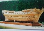
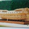
 mij got a reaction from Archi in HMS Sussex by mij - Scale 1:48
Cherry ready for the bandsaw
The cherry cut and ready to be milled.
It was worth the time and effort.
Tulip on the left and Cherry on the right
Start of the new build in cherry.
In the back ground is the one made from tulip.