HOLIDAY DONATION DRIVE - SUPPORT MSW - DO YOUR PART TO KEEP THIS GREAT FORUM GOING! (Only 20 donations so far - C'mon guys!)
×

woodrat
-
Posts
835 -
Joined
-
Last visited
Content Type
Profiles
Forums
Gallery
Events
Everything posted by woodrat
-
Questions about Magellan era Portuguese Carrack
woodrat replied to Salty Sea Dog's topic in Nautical/Naval History
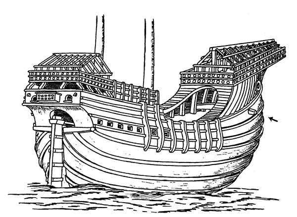
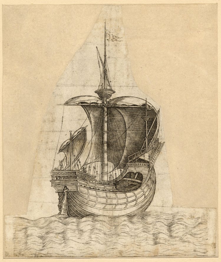
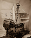
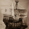
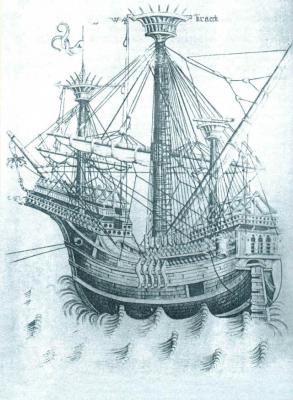
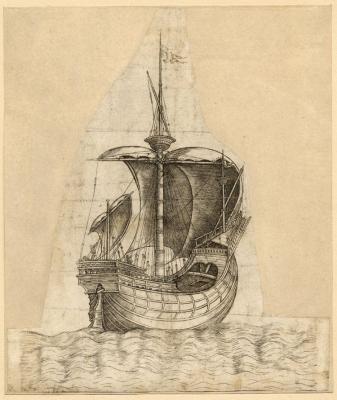
Buck, the basic shape of the hull of this kit is ok. I like the round tuck stern. Does it have a transom timber below the rudder port? However, the sterncastle is way overbuilt.It would probably drag the carrack down by the stern. The rigging is rather wrong and represents a nineteenth century idea of mediaeval rigging and masting. I would recommend bashing the kit. However, as it is it is still a nice decorative model. Happy to help where I can. Perhaps the model could be modified along these lines? It is rather like the Kraeck of Master W A which is a well regarded contemporary illustration of a carrack Dick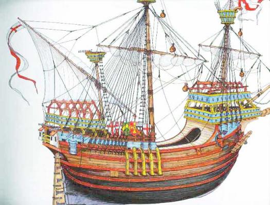

-
Thanks, Steven. An interesting project. I will try to chase some of the publications down. Some of the illustrations of the Lomellina will be useful. I had already decided that a windlass is required in the forecastle and it is good to know they were fitted to these big naves. Dick
-
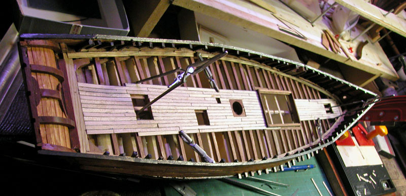
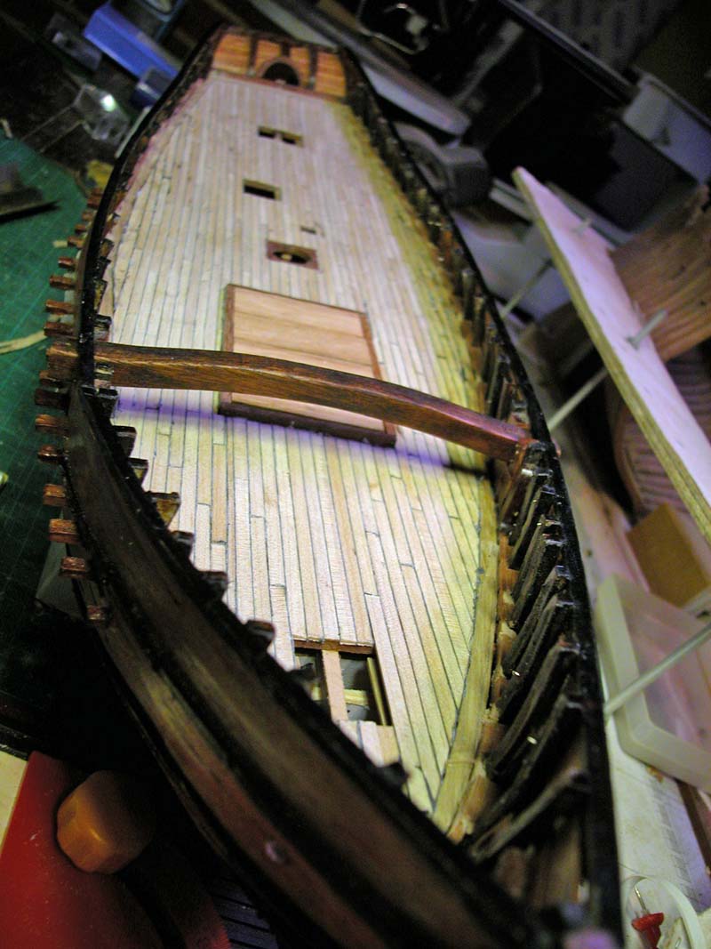
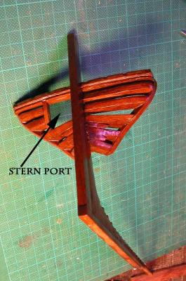
this is the tiller and steering mechanism. This ship would predate the whipstaff. The large rudder would not be controllable without the tackles.

- 632 replies
-
- 11
-

-
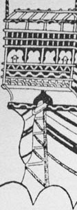
Thanks, Steven. Next is a part of the ship dear to heart of Louie da Fly: the heads, those vulgar tubes so necessary and often detectable in some illustrations. Some illustrations show projections from the sterncastle much as are seen in the gardrobes of mediaeval castles or jar-like containers also projecting which are probably part of the sanitary arrangements. I believe these rounded projections are ceramic bowls which acted as pissdales or urinals for the gentlemen aft of the mainmast. Between these rounded "pots" are often seen box like ventilated structures accessible from the poop deck where I believe are the seats of ease. . These projecting necessary seats are not seen in the Trombetta nave so the seats of ease for the ships VIPs must be internal with lead lined "drops" through the curved base to either side of the rudder It is these internal arrangements that I will build into the stern. Dick


-
Good choice, Alaska. I am happy to help with your build. Please post a build log. What is your build plan, POB, POF? I hope you got full set of plans with the book. I strongly advise a building board as shown in my log if you are going POF. At present I have been sidelined by my carrack build but hope soon to resume the "fat Belly" which has a special importance to Western Australia. Dick.
-
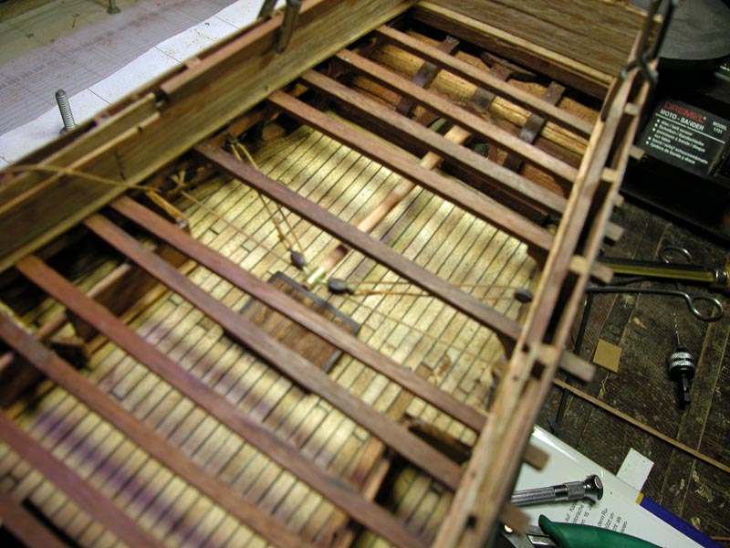
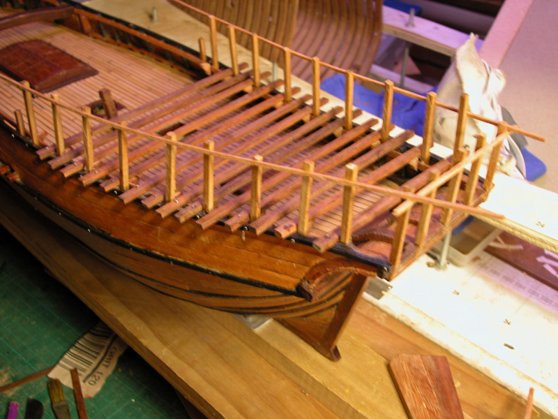
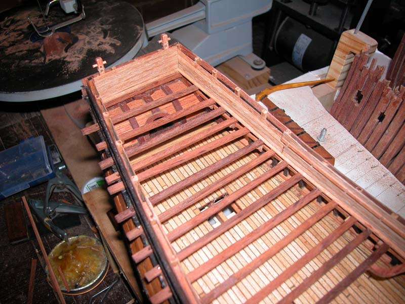
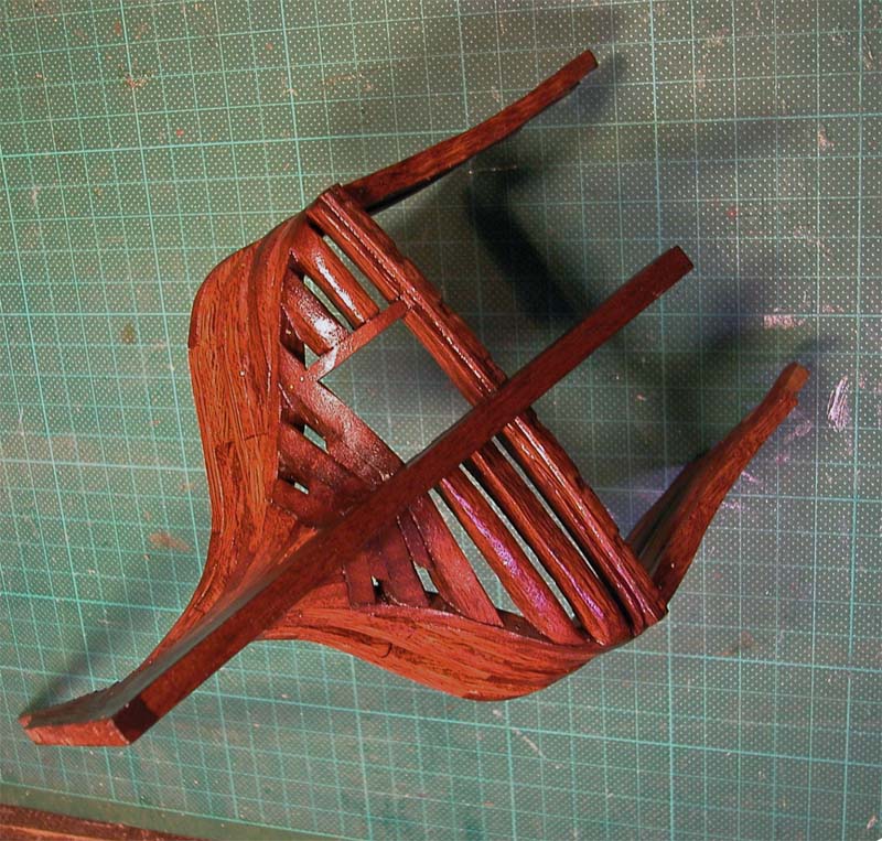
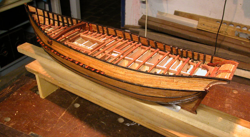
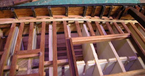
Thanks, Vivian. I am sorry that I cannot fully answer your question about genoese navi of the fifteenth century. What I can say is that not all vessels of this type are shown in illustrations with projecting deck beams. This means that either they did not have them or they were covered by a concealing strake. So the modeller can choose whether to depict them or not and still be correct. The "rib-cage" behind my nave is the presently neglected hull of the Gros Ventre, put on hold while I complete the nave. Dick
-
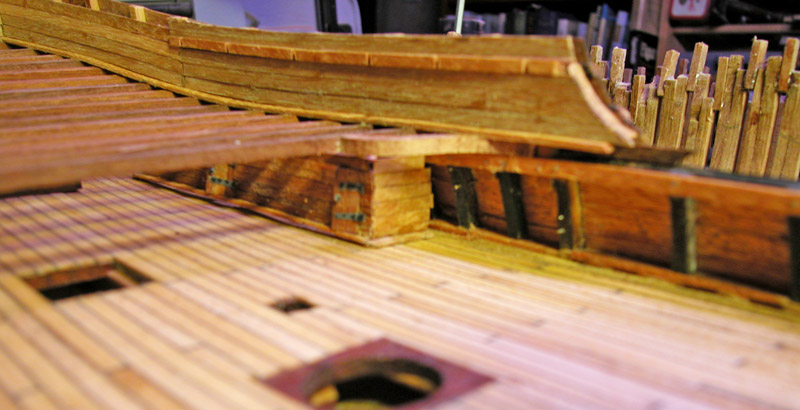
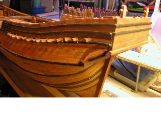
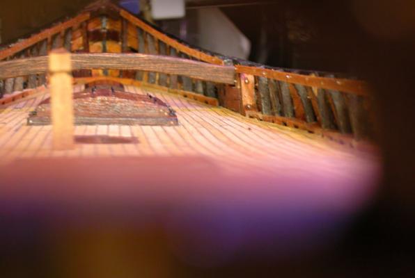
Further progress on the sterncastle of my Carrack ( nave tonda) note the two knights at the stern. These are seen in the original illustration


- 632 replies
-
- 11
-
-
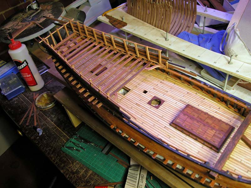
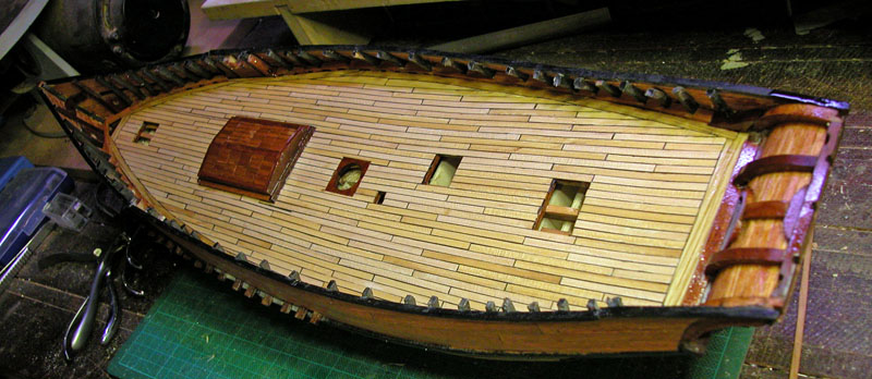
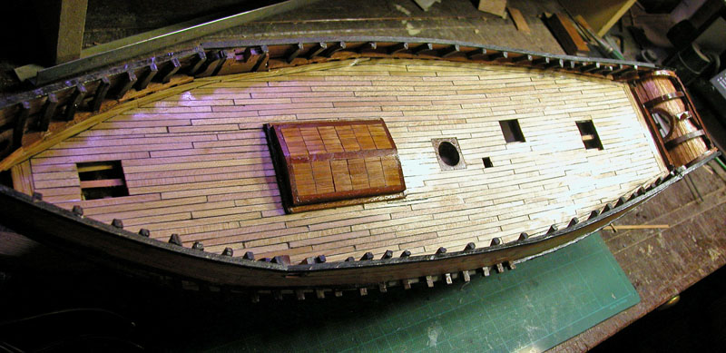
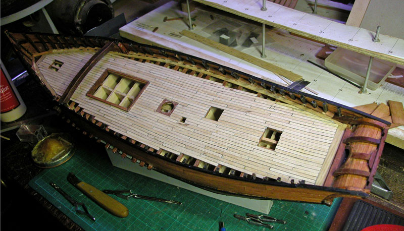
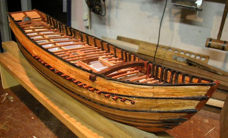
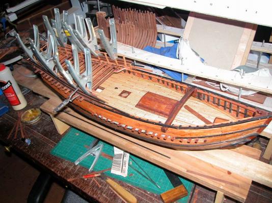
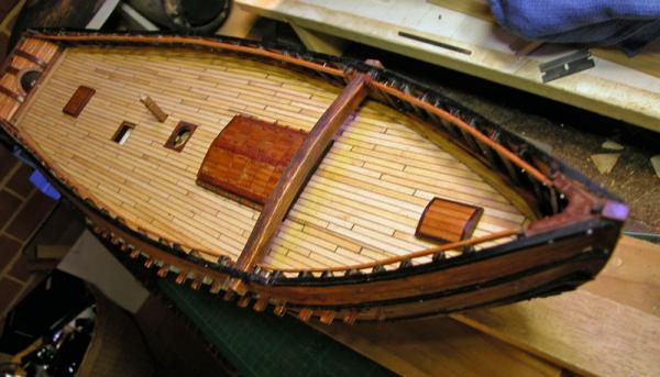
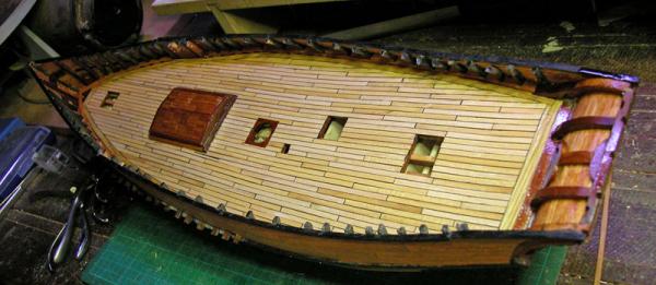
slow progress because of work committments. Hull is complete. Next job is to install rudder and some accommodation in stern. Where should the galley be positioned? Dick through the rudder port.

- 632 replies
-
- 11
-
-
Good luck with this, Sharpie. I will be keeping a Sharp eye on your progress. But a warning, the more you delve into the literature and the archaeology, the more you get dissatisfied with your build. I did a half hull model on my carrack before launching on to the full hull and thereby was able to sort out a lot of mistakes. You have done an excellent job on the trireme so I am probably teaching you how to suck eggs. Cheers. Woodrat
-
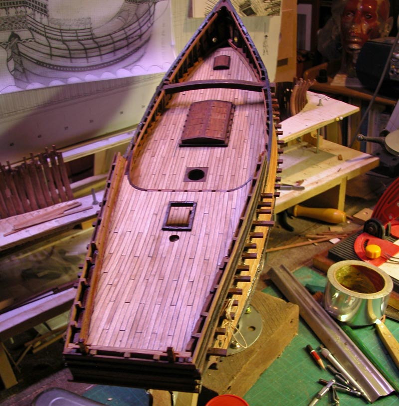
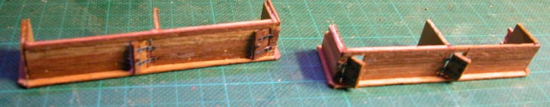
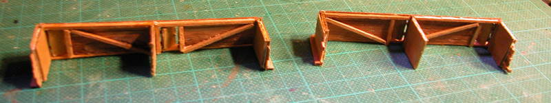
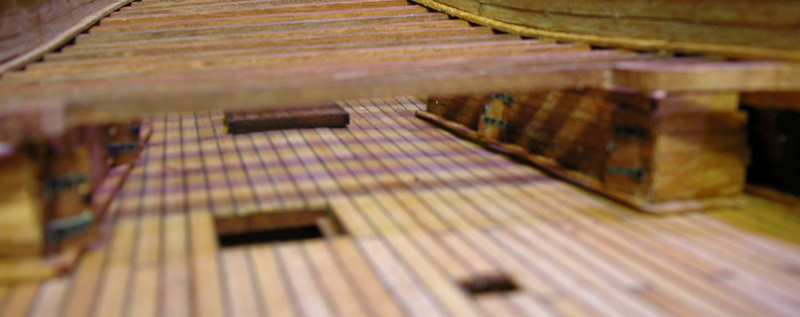
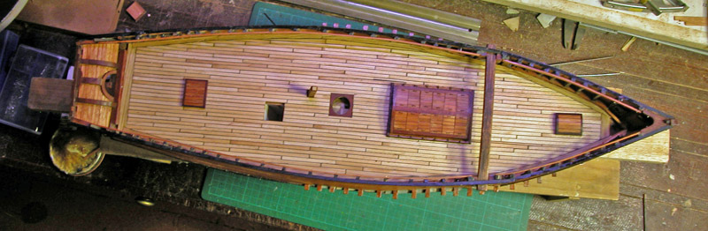
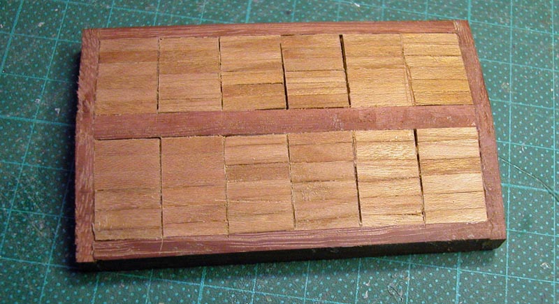
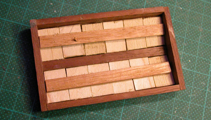
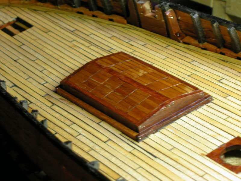
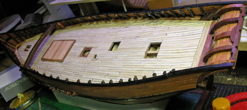
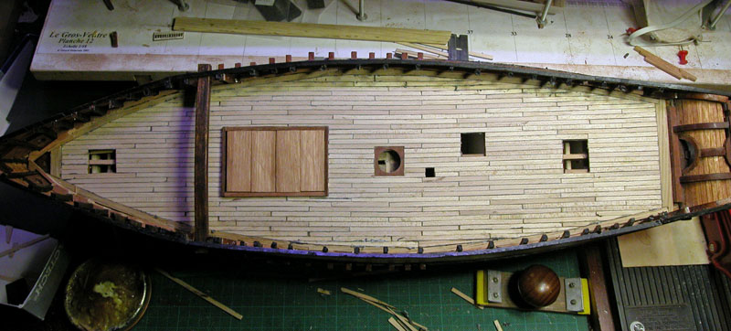
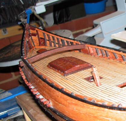
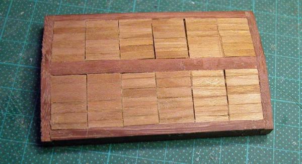
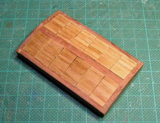
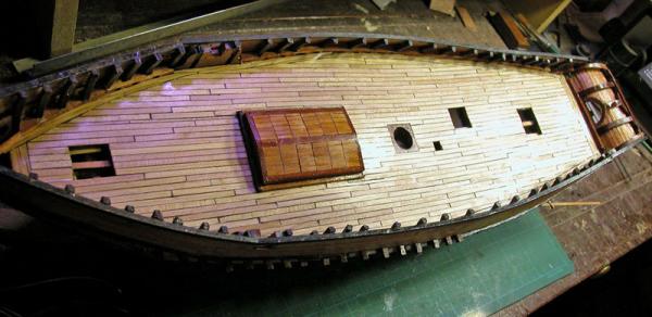
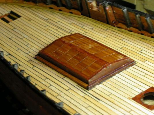
Thanks. Vivian. Here are some pictures of the main hatch. I tried to keep in mind the practicalities of a hatch which would have to be manhandled by a brace of sailors. The overall shape is that seen on the Mataro Nao. The individual sections of the hatch could be lifted by two men. Bear in mind that the overall scale of the model is approximately 1:64. Cheers, Dick

-
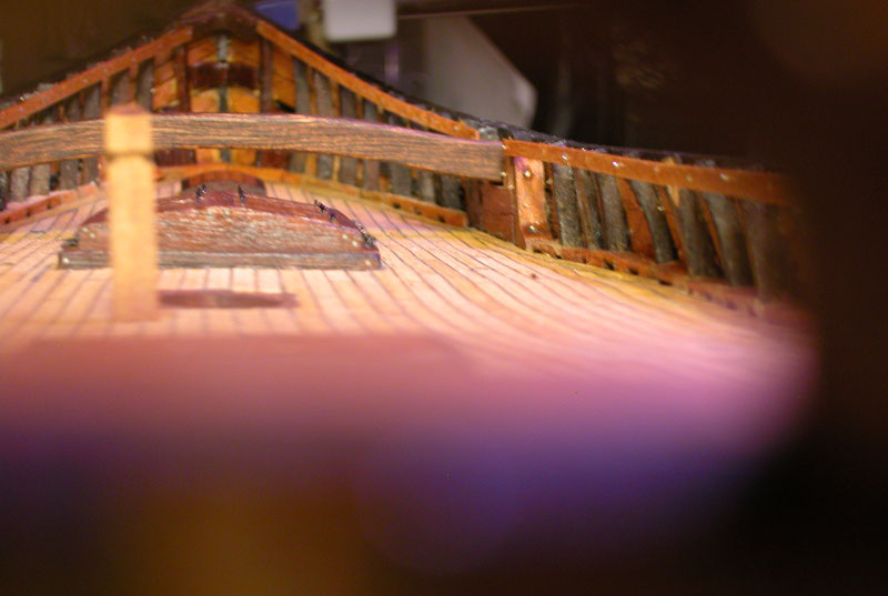
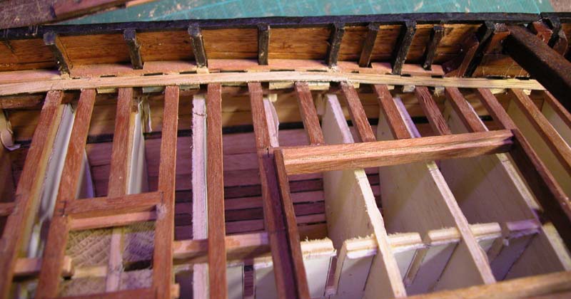
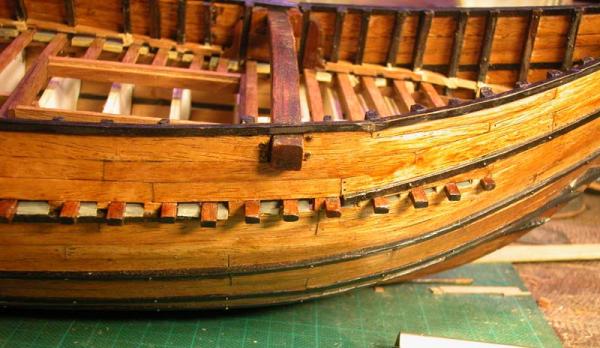
thanks, Farbror . Most of what we talk about regarding mediaeval ships is guesswork but it is very interesting. Here are my ideas about why the deck beams are projecting. I think this is how they may have done the scuppers in the waist. The scuppers exit between the deck beams and are lined with leather or lead. Dick
-
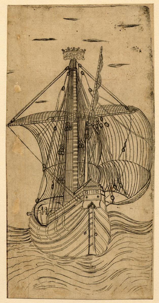
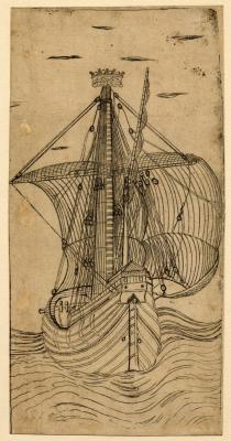
And not necessarily call them Santa Maria! There are no sources which detail the exact configuration of the Santa Maria, of which there are many models( although were it not for all the obsession with this ship, we would not know nearly as much about these vessels), yet there are excellent pictures of naos (naves, nefs, cocha, carracks,etc.) which give the modeller excellent fuel for creativity. The Mathew is a good example of what can be done. Steven, the Breidenbach hull is interesting as it shows a curved sternpost like a galley so presumably it had a curved galley style rudder. The second picture comes from the British Museum collection. Dick
-
I also made similar mistakes, Tom. It is all part of the journey. Dick
-
Tom I am concerned you may have rounded of the aft edge of your frame which will mean you may have an unsigtly transition to the next frame, in this case the filler timbers below the transom timbers. I think the aft edge of the chamfer should be sharp and to the line indicated on the plan. Cheers. Dick

-
you have to do it yourself. Make the pieces oversize and Dremel them to shape. Dick
-
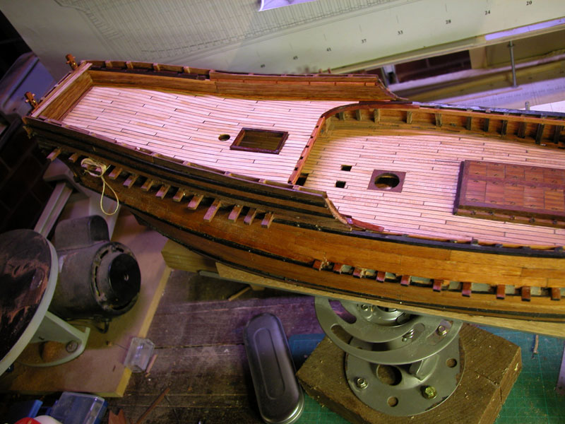
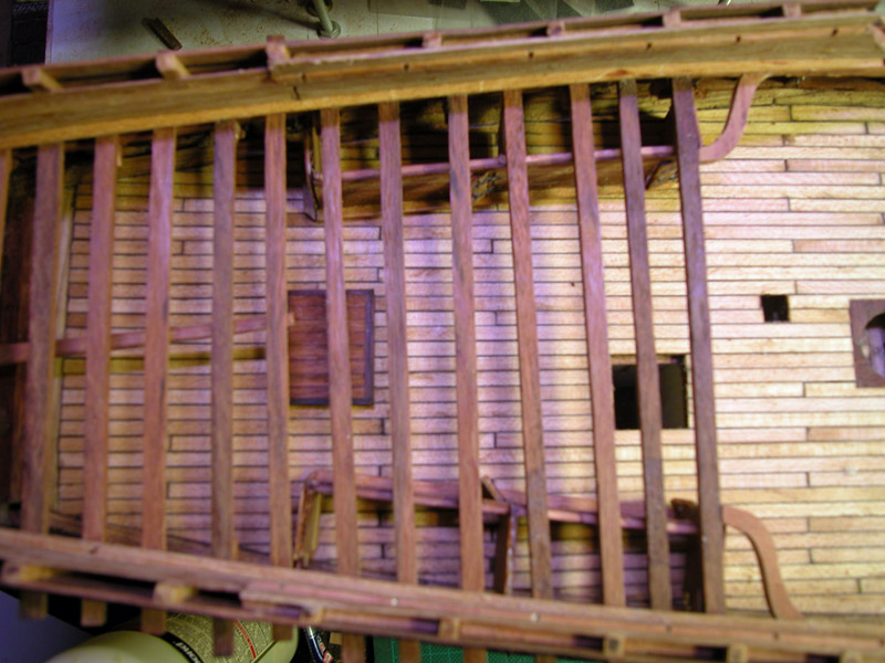
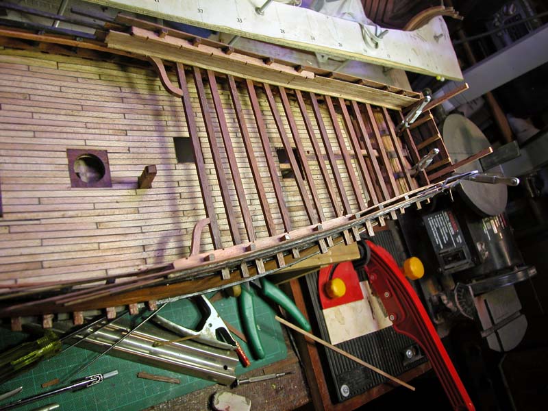
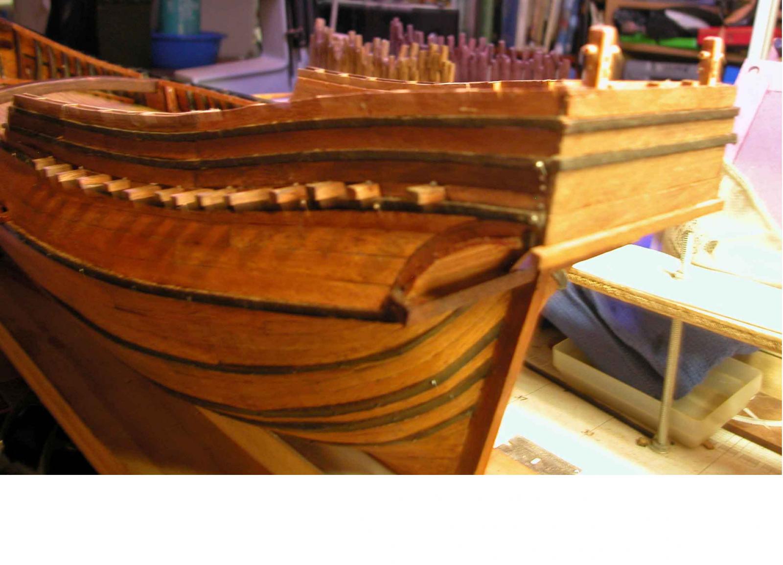
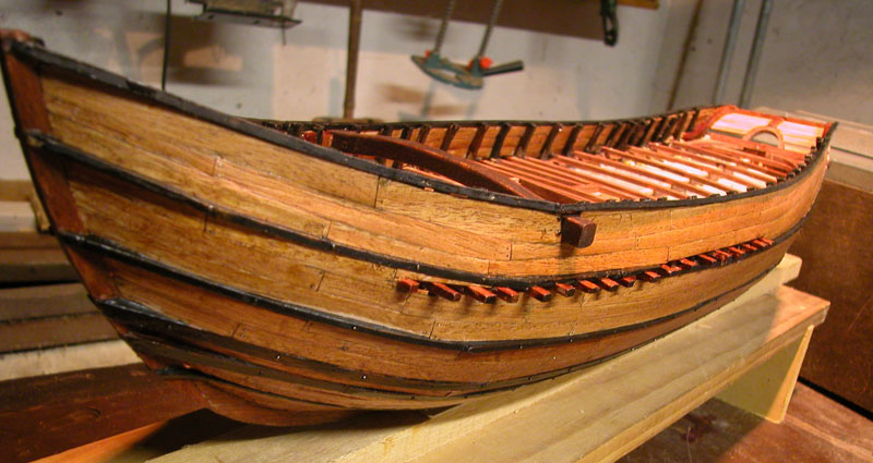
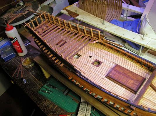
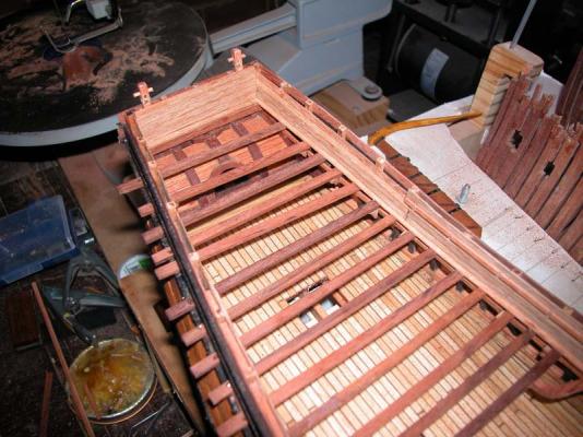
The fact that the beams cross the wales confirms to me that Zorzi Trombetta drew his sketch from life and probably while the nave was in drydock( hence the unplanked area between the main wales). This is one of the reasons that I chose this sketch as a basis for a model. Most other paintings are by professional artists interested in aesthetics whereas Zorzi was primarily interested in recording the craft of shipbuilding. Doreltomin. Thanks for the scholarly breakdown on the derivation of Carrack, with which I substantially agree. However, when you say: "The nao being primarily a merchant vessel while the carrack was primarily built for war", it does not take into account that in the late middle ages, mediterranean round ships ( naos or naves or nefs) were sometimes hired or recruited as warships even though they were built as merchant vessels. This is because it was soon realised that the high freebord of the round ship was a great protection against the low slung galleys of the corsairs. Only later were purpose built round hulled warships developed. It is a fascinating topic, isn't it? Dick
-
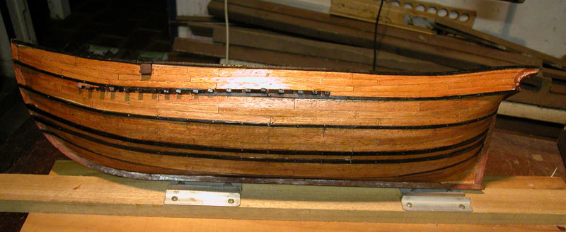
Thanks, Bob. It has a rustic charm, I suppose! The colour may be too light. What do you think? Dick
-
nil desperandum, Tom. No need to remake the knee. Much as Karl has shown, after you have completed and fitted the transom timbers, fashion piece and last 2 frames, simply fit some timbers below the lowest transom beam and shape them in situ with your friendly Dremel drum sander. Dick Another point. Please note there is a step at a slightly lower level for the step of the forward half of the full frame. It also has a hole for a dowel. You do not appear to have done this.

-
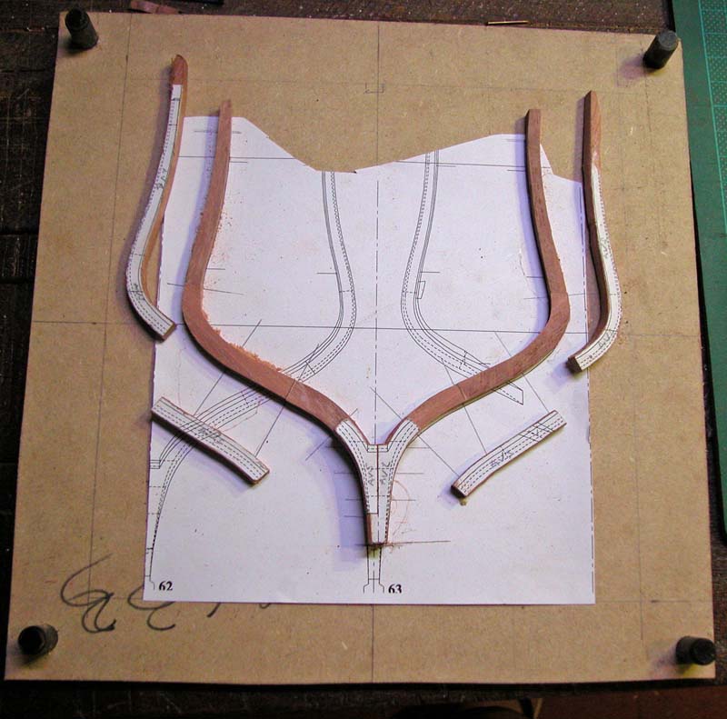
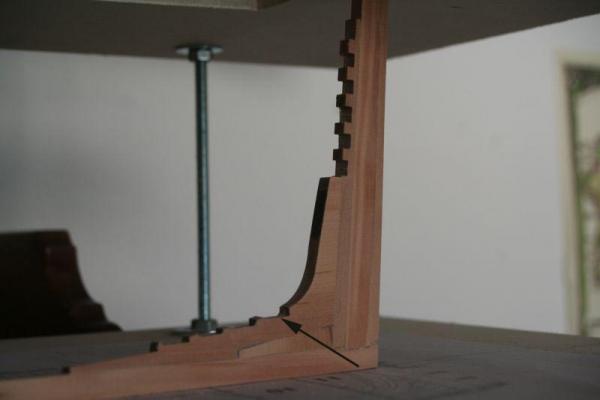
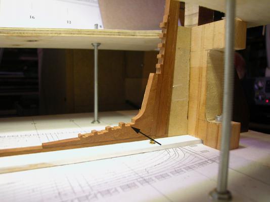
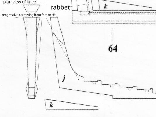
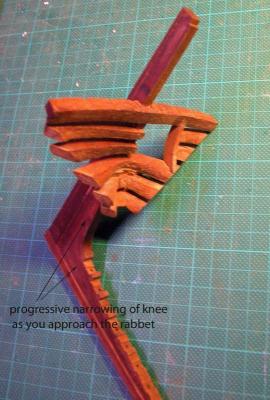
Tom, the drawing shows the sternpost knee and filler from aft. On top is a plan view. This shows the progressive narrowing of the knee as you go from fore to aft towards the rabbet in order to accommodate the run of planking. I hope this helps,. Dick
-
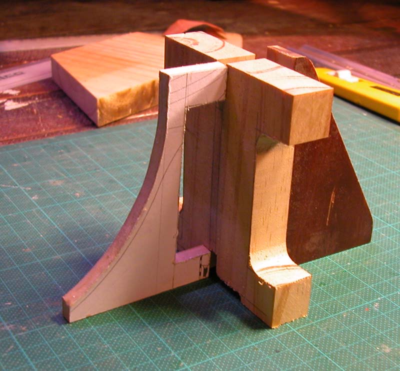
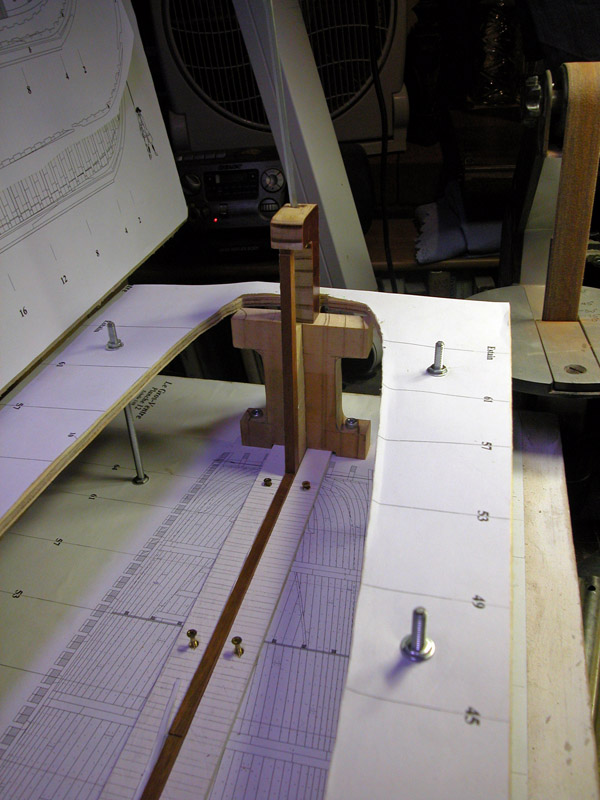
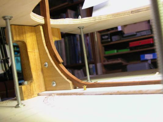
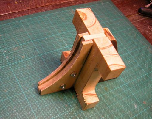
Tom, I highly recommend that you construct frames to rigidly hold the stem and stern posts. also take care that the keel is held by wood planks which go almost up to the rabbet line of the keel. here are some photos of the ones I made stempost clamp sternpost clamp. Note the allen key in the top of the clamp to tighten the bolt thereby holding the sternpost down. This will reduce the risk of twisting of the hull over time :) Dick


-
Tom, are you making clamps for keel, sternpost and stempost? Dick