


dashi
-
Posts
248 -
Joined
-
Last visited
Content Type
Profiles
Forums
Gallery
Events
Posts posted by dashi
-
-
Thanks Paul it seems the problem port lid is the one under the channels like you mention. I've looked at that on the 1768 draughts and the kit plans and to me it looks like a full size port lid which makes 5 large port lids on each side of the hull plus 2 at the waist on the quarterdeck bulkhead and 1 on the port forecastle hatchway. I'm still short a set of hinges for the port forecastle hatchway so I might have to do something different there.
There also seems and over abundance of long open lid hinges so I might be able to modify some of those and or try and have some of the hull light port lids open?
-
Thanks Ron.
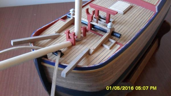
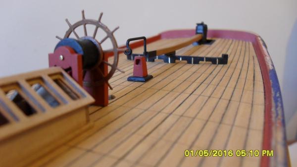
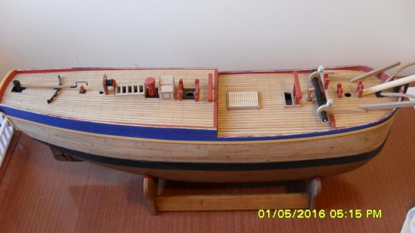
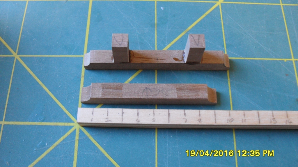
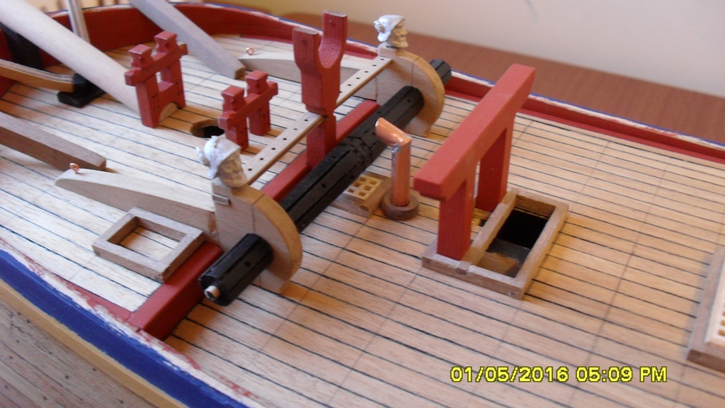
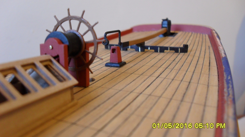
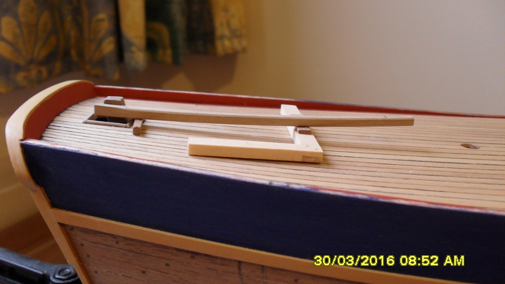
After successfully bashing a pair of replacement windlass standards from the sheet that the originals came from I thought I might post some progress photo's of where I'm at rather than wait until the deck furniture and deck are finished. Everything is pinned and dry fitted to the deck and uncompleted at this stage.
The pencil lines crossing the deck are marking the beam centres for when I ink in the butts and trunnels.
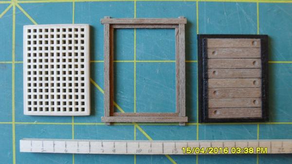
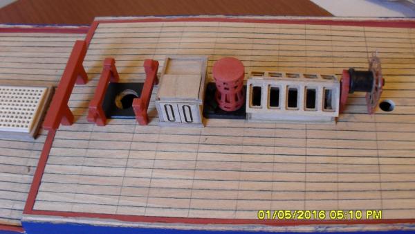
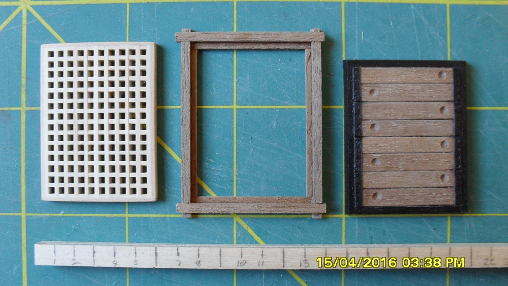
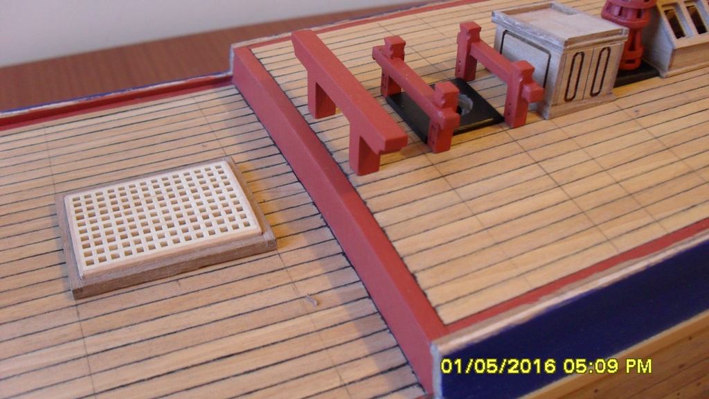
Most of these photo's refer back to my previous post #77. The main hatch on the right is my first attempt from following the kit and so is too small. The new hatch on the left is closer to scale at 9x7'.
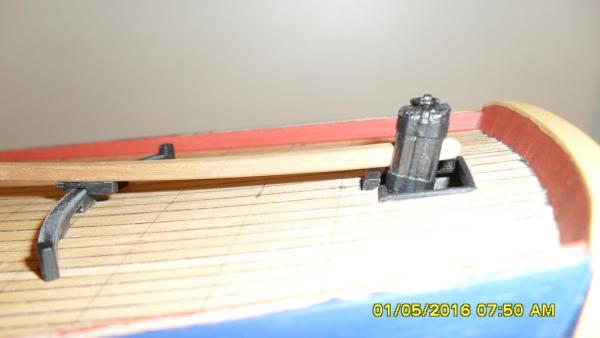
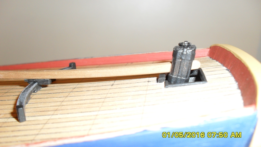
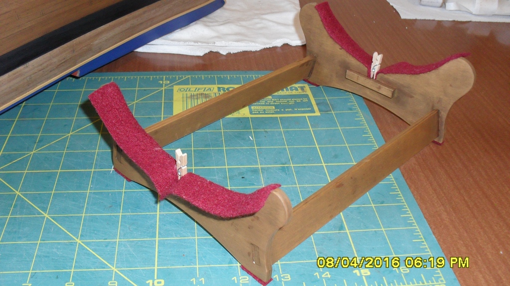
I've also included my bashed 'Tiller Sweep Support', from the discussion that can be found here: http://modelshipworld.com/index.php/topic/13109-hmb-endeavour-tiller-and-steering-question/page-6%C2%A0 which I've briefly mentioned in post #66 of this log but to recap based upon the navy deck draught of 1771, The Arming and Fitting of English Ships of War 1600-1815 by Brian Lavery part 1 Steering, section 2 Tiller and Whipstaff and the physics that we worked out. Unfortunately I've had no answer to the replica tiller. I'm not an engineer so could be wrong but we worked out that the physics of a projecting 19 foot tiller unsupported made from 9x9" to 7x7" solid oak including 3 foot of solid iron tip would generate around 2 ton of cantilever pressure while at rest in the rudder head. It would blow apart if unsupported! Therefore we suspect that the replica tiller is made from modern lighter and stronger material so unless new information comes to light I can't use it as a historical reference. For these reasons and again unless new information comes to light the tiller sweep support is assumed to have been fitted along with the tiller that we can confirm was in the 1768 navy draughts.
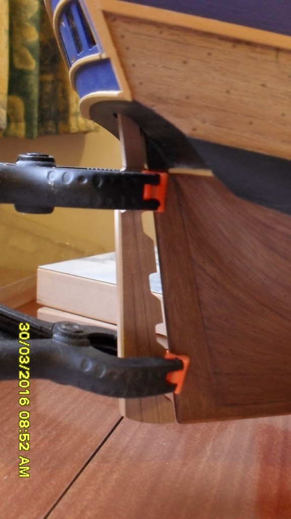
The tiller sweep support is made so I can do a refit should our findings be proven incorrect. How it is made is by soaking and then glue laminating two lengths of 4x1mm walnut together around a container which had the correct diameter. Then I shaped it to the deck camber and then realized it needed to follow the vertical arc of the tiller. Then I filled scuppers under it and fretted some 0.5 brass into it's face to mark the 1/4, 1/2, 3/4 and full rudder positions. On it's upper surface I glued some black card to represent a metal runner and decided on painting it black because it would have been greased. On the underside of the tiller is a small block that rides on the runner. I've added stops which made sense to minimize damage should the tackle break.
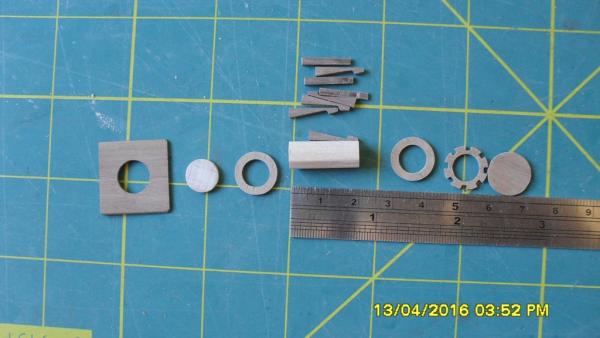
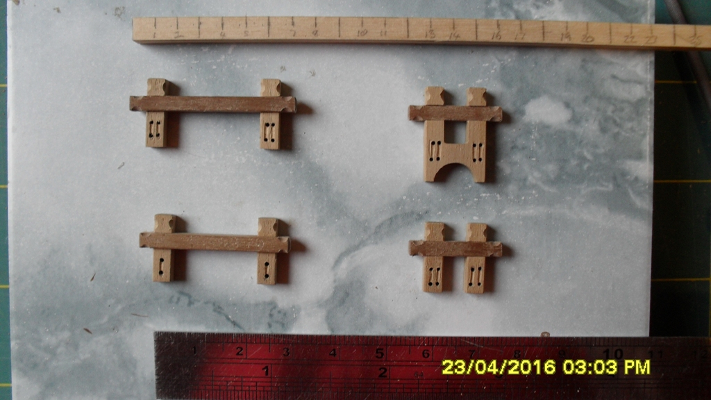
Post script: For the wheel drum the kit uses a 6mm dowel which is smaller than scale so I've used and 8mm dowel sanded down to 7.5 mm with thinly sliced 10mm dowel on the ends. It has a capped removable pin which I'm still refining and turns. The capstan I've used card to make some rings. The pawls are made out of wood and brass.


-
Kit question for those who have built this kit:
Part 244 Light Port Lid Hinges 0.5mm Brass. The kit supplies 24 on the brass sheet as indicated in the manual, but there are 13 lids including the forecastle hatch that use these meaning 26 hinges should have been supplied. How did others work around this problem or do I have an outdated kit?
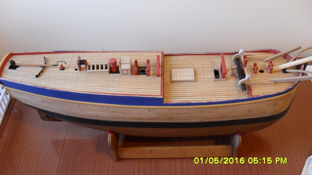
As for progress I'm slowly working my way along the decks working out where the beams are. There are continuing problems with the scale of some of the deck furniture and hatches.
Rudder: I've also had to increase the width of the rudder head in addition to the depth in previous photos, to bring it up to scale so it now looks right.
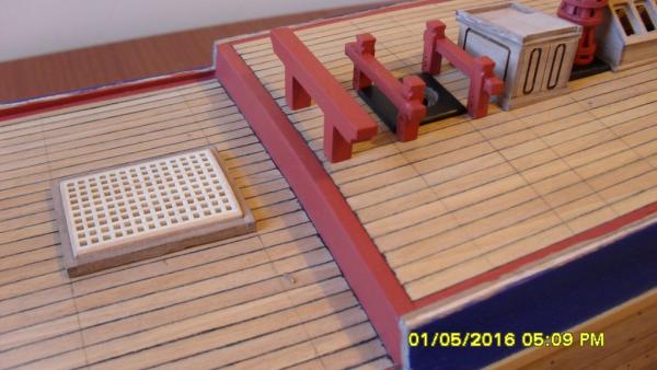
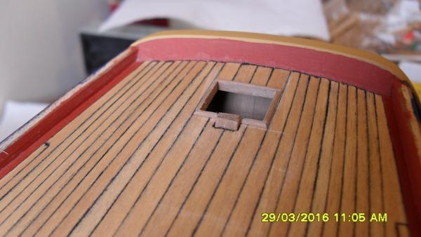
Waist hatches: The waist hatches are just wrong going by the AOTS book and Admiralty draughts. @ 1:64 scale 1' = 3/16" or approx 5mm. So working at 1:1 scale the main hatch needs to be larger 9'x7' and the fore hatchs smaller at around a standard 2' width. I've used a grating in the main hatch.
Quarterdeck the covered hatchway: Is too high by about 1' meaning the average short sailor at the time wouldn't be tall enough to open it.
Wheel: The support posts also need to be reduced in hight by just under 1'. Bearing in mind they will end up at different hights because of the angle of the quarterdeck.
Quarterdeck spar gallows: This is too narrow so dosn't even match the kit plans and should be at least the same width as the Forehatch spar gallows. Bashed a replacement.
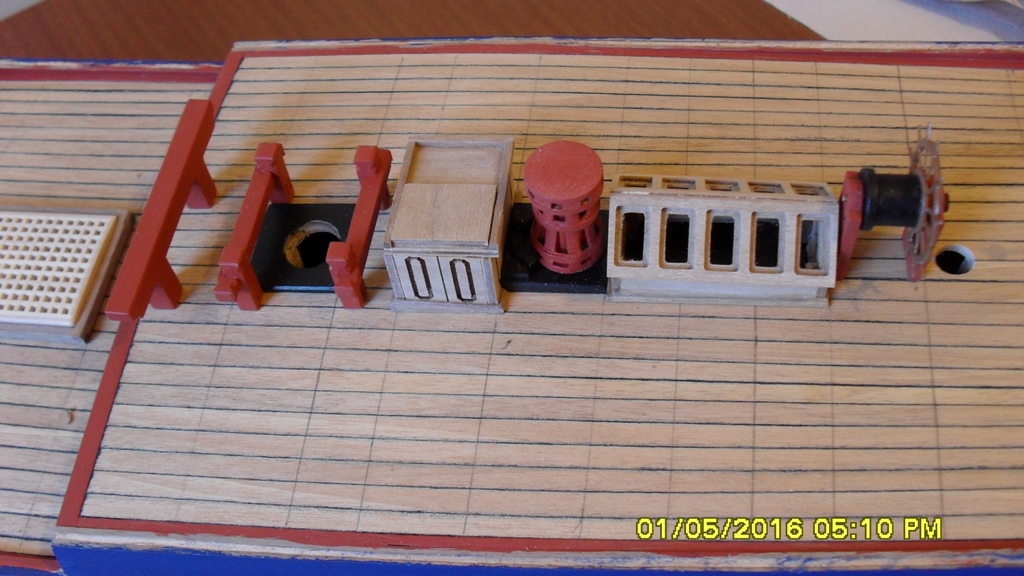
Great cabin flu: Not supplied in the kit so bashed this modelling it on the replica as I think if would have been a wooden cowl which can be turned depending on the direction of wind and which would be less likely to burn the tiller tackle should they come in contact with it.
Windlass: The standards are short by about 1' so don't reach the deck beam like they should which passes fore of the fore topsail sheet bits and which also supports the bowsprit and cat heads. So these might need to be cut off and new ones bashed. The barrel head is too wide by about 1' meaning each inner barrel need to be around 2mm shorter which also brings the bit chucks and standards closer to where they are shown on the AOTS book and navy draughts.
Main Fire: Didn't like the kit supplied flu which looks like a cannon blank so bashed the flu from some copper tube and based the vent grating under the windlass which isn't supplied in the kit.
Foretack bumpkins: Look to be postioned wrong and don't pass under the cathead but swing closer to the bowsprit and pass over the false rail leaving enough room to bash a foretack bit and seat of easement between it and the cathead. If the bumpkin passed under the cathead then... well you can imagine the mess as it would be in the line of fire from the seat of easement, but also the stays would be in the way of the anchor tackle. Seats of easement are on the navy draughts and replica so I will add these. This new position also matches the sketch of the Larboard bow by Parkinson entitled 'Wie View of the entrance into the Bay of Aware, Huaheine AA', which clarely shows the bumpkins. With the bumpkins in this new postion they now run clear of the anchor and cat tackle with the anchor rope passing under bumpkin stays when the anchor is stowed on the rail.
Knightheads: Will need to bash replacements for these.
I hope to post some pics when I've completed and inked the deck trunnels and butts. More work do be done on deck furniture to get me to that stage.
-
Heads up!
A scale problem I have just discovered is that the main deck is short by 2 - 3feet @ 1:1 or 10 - 14mm @ 1:64. I initially thought just the forecastle was too long, but it appears that the quarterdeck is also equally too long (both by 5 - 7 mm of where they are drawn on the AOTS book and 1768 drafts, therefore making the main deck too short. It's too late for me to fix and it would mean moving the offending plywood frames forward and and aft by a ply frame thickness at the start, then extending the false maindeck ply to cover this gap. Seems whom ever drafted the kit plans drew these frames on the wrong side of the line?
Also some small repairable scale errors with some of the deck furniture which I'll try and document at a later date.
-
I'm slowly making my way through the Caldercraft kit and striking some minor and not so minor scale issues. Also the walnut is pretty scrappy as it tends to split. Apart from this the rest of the kit seems well thought out and the parts are of a good standard.
The minor scale issues involve not allowing for planking thickness on the bulkheads at the keel and parts of the plans and some lazer cut parts which if they are too big can be reduce but if too small then it's a kit bashing but all seem fixable if you stay alert and check the scale of everything step.
The major scale problem I have just discovered is that the main deck is short by 2 - 3feet @ 1:1 or 10 - 14mm @ 1:64. I initially thought just the forecastle was too long, but it appears that the quarterdeck is also equally too long (both by 5 - 7 mm of where they are drawn on the AOTS book and 1768 drafts, therefore making the main deck too short. It's too late for me to fix and it would mean moving the offending plywood frames forward and and aft by a ply frame thickness at the start, then extending the false maindeck ply to cover this gap. Seems whom ever drafted the kit plans drew these frames on the wrong side of the line?
-
Hi John, I also have an interest in one day building a scale Maori canoe or Waka. From my whakapapa or family history on my mothers side which is traced back hundreds of years in recorded tribal history, they came to New Zealand in double hulled canoes. When they arrived they split the hulls into two single canoes. They were advanced stone age boat builders, navigators and farmers. Of interest to me also is that they must have had contact with South America because the word for the Maori sweet potato that they brought with them to NZ is Kumara, which it is also called in South America where it must have originated from.
Looking at the hulls of the Maori canoes they are made from lashing strips of adzed wood together to make up the wale which are lashed to the hull. The hull is a dug out carved from one tree. It appears to be similar to the method the Egyptions used to construct their vessels. Considering some Maori words also appear in Sanskrit then I wouldn't be surprised if the Polynesian method of boat building, navigation and farming could trace it's roots from the late stone age/early bronze age culture and people.
Here is a link to a page I just found with photos of what appear to be traditionally made and carved waka.
I don't have time to research all this at the moment but will follow this to see what you find and end up building. Best of luck with this venture.
-
Hi Daniel a very impressive rebuild you are doing. You were asking about a rabbet in the stem to take the wale. If you look at photos of the Endeavour replica you will see that the wale dosn't thin but keeps an even thickness as it meets the stem. So I'd imagine that there would be a separate rabbet stepped out to take the wale strake butts which is also shown in the AOTS book. I posted a photo on my Endeavour log of the rabbet I cut in the stem to take the wale, post #41.
Just my 2cent thought about the method of planking the wale. A colier would need to withstand the constant loading and unloading of cargo tonnage. This would mean the hull would need to withstand extreme changes from loading stresses as part of it's job. Where as I'd imagine a war ship will have a more constant stress from cargo weight loading, as it's basic cargo wouldn't change that much but instead would need to be braced against cannon firing and battle impact.
-
Ships pivot around the head from rudder movement, it is the stern that swings, that trait saved my ship 'the Ammen' from being cut in two during a collision, just enough time to start the swing, so the other ship slid down our Port side. 19 July 1960, USS Ammen DD 527, killed 11 injured 25.
jud
This has been crossing my mind so I looked it up. Thanks Jud for sharing this and emphasising the importance of reliable steering geer, as this tragic accident could have been much worse like you say. An importance that would have been quickly learned and well understood throughout the ages I imagine.
With this in mind it would seem even more likely that the Admiralty would have put every effort into making HM Bark Endeavour the most technologically reliable vessel in their fleet so she could perform her important mission which involved a 3 year voyage into uncharted waters that would take her and her crew weeks or months away from any known safe port.
So I'd imagine they would not have skimped when it came to the Bark's helm and therefore another reason that makes me think (unless information to the contrary comes to light) that the tiller sweep support is not part of the 1771 refit but an existing intregal part of the helm gear since atleast the Admiralty refit of 1768 if not from her date of build.
Something I will try and keep in mind while building my interpretation of the HMB Endeavour from 1768 whilst in the relative safety of my studio.
Thanks again for everyones input into this discussion which I'm learning a lot from.
-
Thanks for the likes and comments guys.
Chris if there is anything you like then by all means use it your model. I usually work through a process of concept, research then trial and error. And after around 3 attempts at trial and error I usually settle on a solution I can live with which is by no means authoritative and probably a compromise due to my lack of ability, research, kit, budget and material restrictions. As part of this process I try and make everything so it works in practice on the kit like a proof of concept. This is all a big learning curve which I get a lot out of, but due to physical health restrictions can be difficult and exhaust me which is when I make lots of mistakes and have to try and pace myself. So I hope you don't copy any of my mistakes :-)
Robin I just went and took a peek and it is something I didn't research due to Caldercraft kit design and material restrictions. But a good topic. So just went with the kit on the wales which used 5x 3x1mm walnut strips which I filled, sanded and painted so you can't really tell which method I have used. However I am very impressed with Chris's wale and hull which I recommend you have a look at if you havn't already.- robin b, Captain Slog, jud and 1 other
-
 4
4
-
Ok Robin I found it thanks very interesting and looks to be at quite a larger scale than 1:64. If you look back over my log you will see I ran into problems with my first layer at the bow and due to this found this photo of the replica which follows the run of the frames which worked nicely for this kit. All the comments from those of us who have built the Endeavour bluff hull will tell you she's a baptism of fire.
Here's a link to the bow of the replica as she was being built which I took my lead from which I think will answer your question.
-
Dash your hull is looking so buitifull and fine finish.I imajine grassing my finger along the wood. Very nice .I am pusald by the run of the planking second layer it is at odds as to what I believe to be correct . the David antcherler blog bow as he demonstrate it seams what I think of. Please could you explane. I do have difficulty looking on this tiny tab so may be I have not under stood robin
Thanks Robin for looking in. For the second layer of hull planking I was following the run of the replica as best I could with the minimum kit supplied splintery 90 4mm x 1mm lengths of walnut at 1:64 scale. So can you provide the link to the 'David antcherler blog bow', as I'm not sure what you are referring to?
-
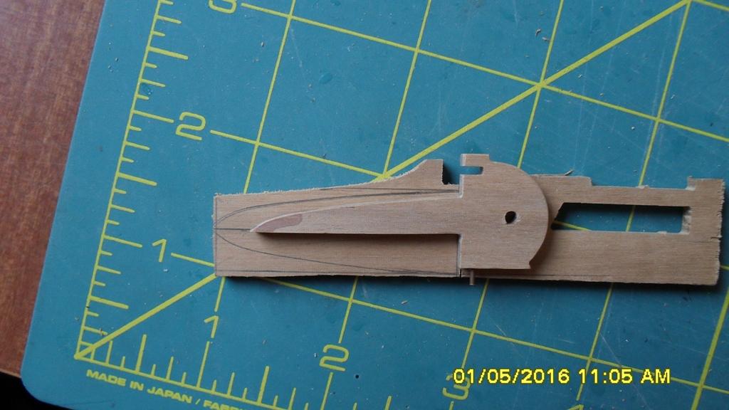
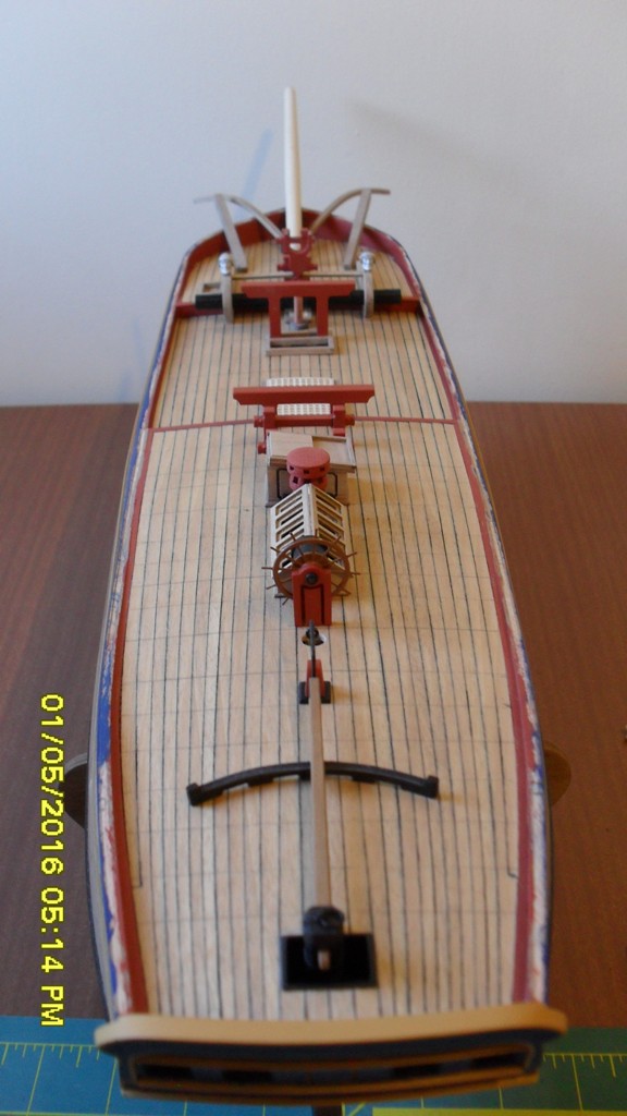
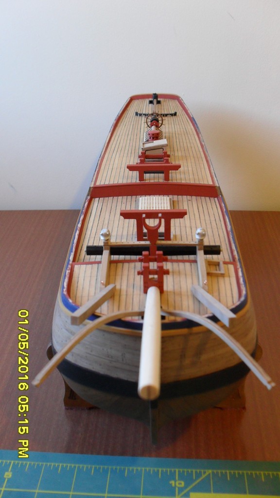
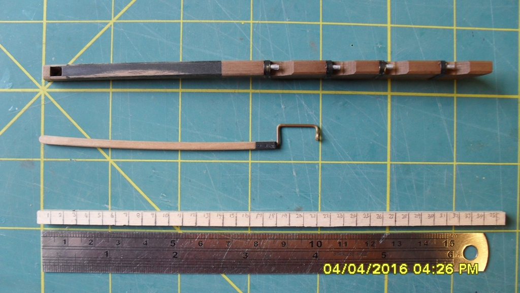
The Rudder:
Here's some photo's of where I'm at. I was researching the positions of the deck beams because I wanted to know the positions of trennels and decking butts which led me to start a discussion regarding a tiller sweep support I found on a deck plan of HMB Endeavour which can be found at the link below. It is from this discussion that I will be attempting to build two versions or interpretations for the Endeavour helm in a way that they can be refitted depending on outcome. It is also from this discussion that we work out the correct position and rigging of the helm blocks and tackle to clear the chimney flue from the great cabin while solving the helm rope slack problem.
http://modelshipworld.com/index.php/topic/13109-hmb-endeavour-tiller-and-steering-question/page-6
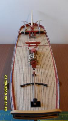
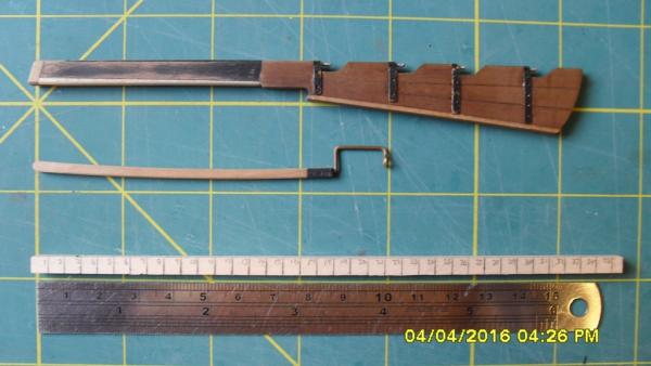
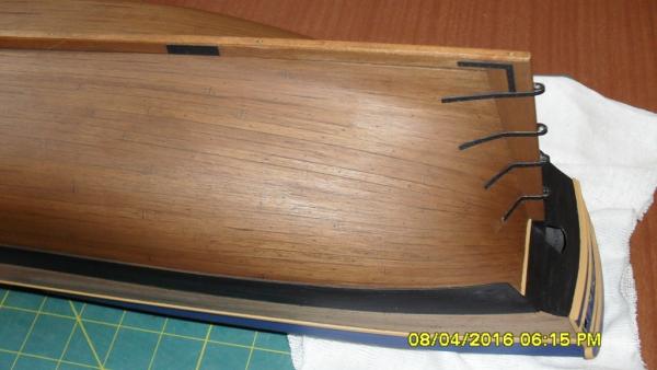
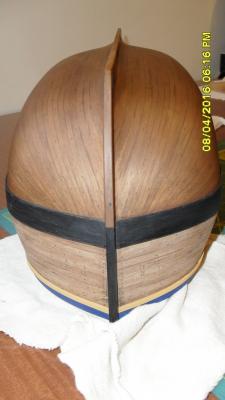
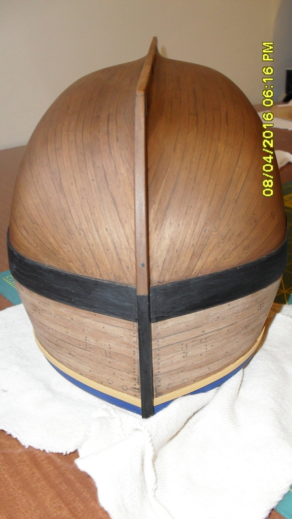
So what I've discovered from this is first that the Caldercraft rudder stock and head are too short by at least 6mm and not deep enough by around 2mm, so not to scale. The photos represent a several attempts and redoes to fix this. More research is needed to finish the rudder head.
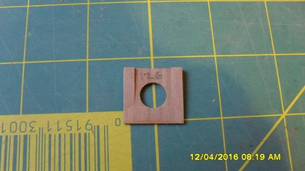
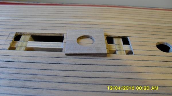
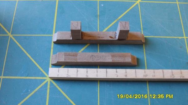
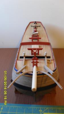
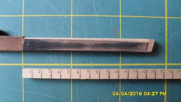
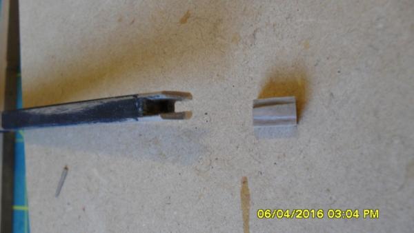
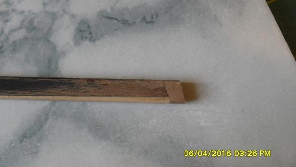
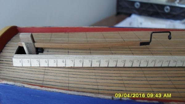
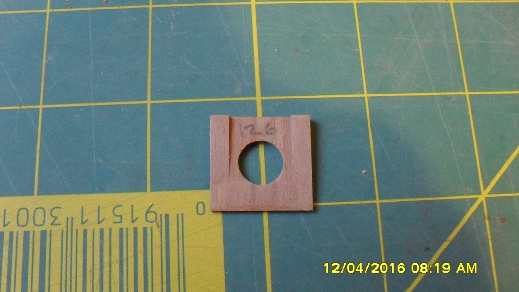
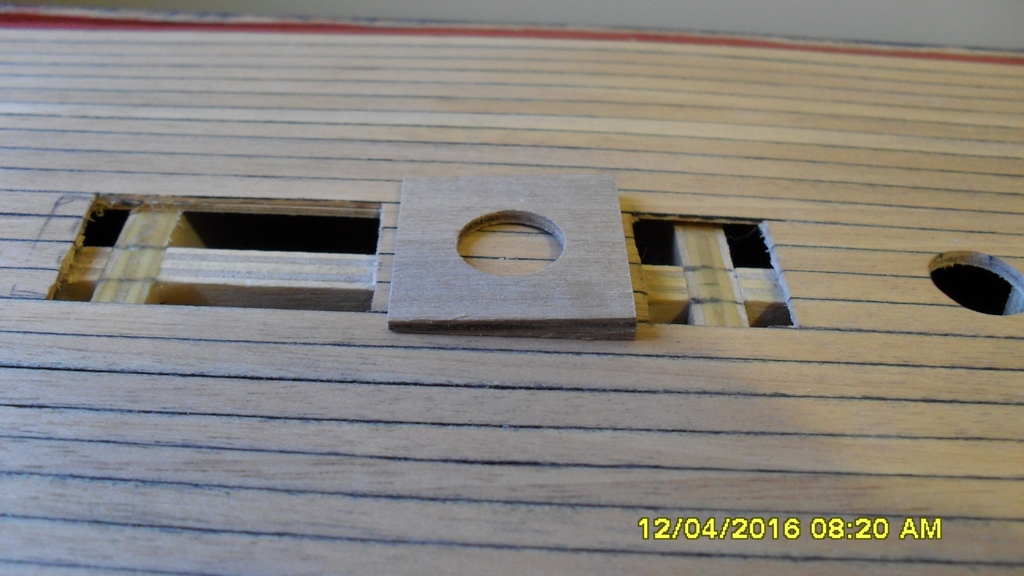
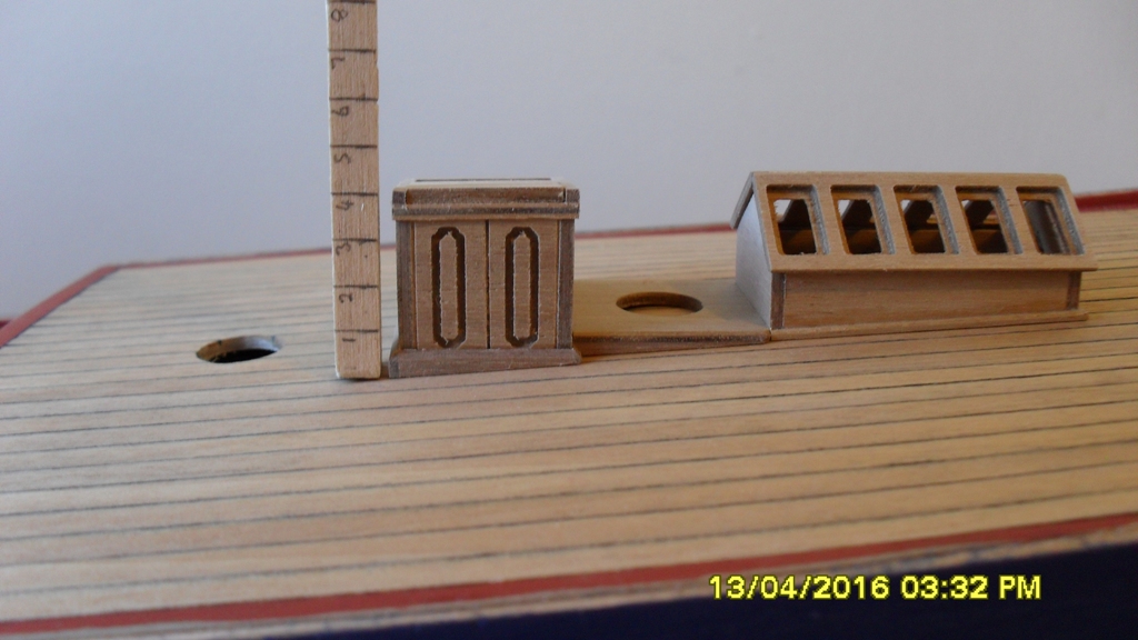
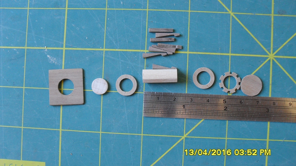
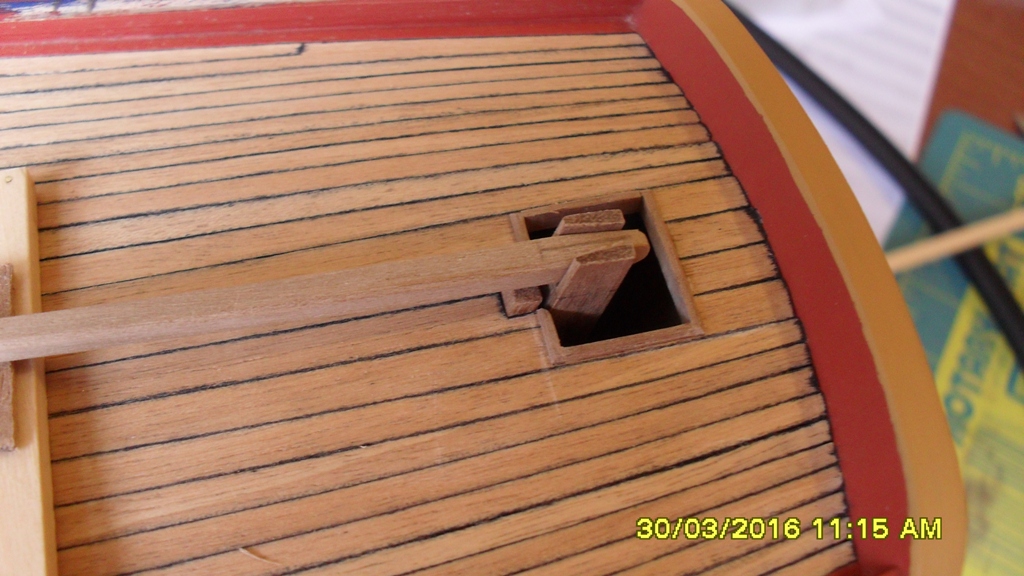
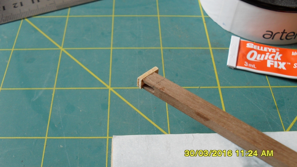
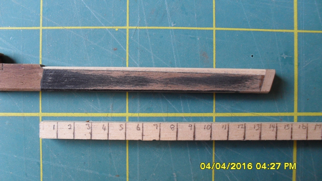
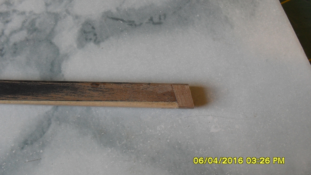
The kit tiller is the correct length however it doesn't fit into the rudder hole so I've also bashed a new tiller to match the scale and shape of the original from the 1768 draughts. I couldn't bring myself to paint my tiller red, so have stained it. I've also decided not to use the kit tiller uplift attached to the end of the tiller, but instead to bash this from 1mm brass wire. I will bash the chimney flue from the great cabin which this uplift is used to clear as this isn't included in the kit either. The scale rule in the photos is marked off at 1 ft intervals to help me maintain the correct scale which seems to be an ongoing problem with this kit. The 1768 plans also show the stern post protrudes the quarterdeck, so I've added this and framed the rudder hole which also isn't included in the kit either. So some bashing.
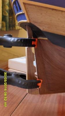
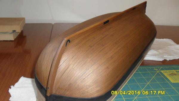
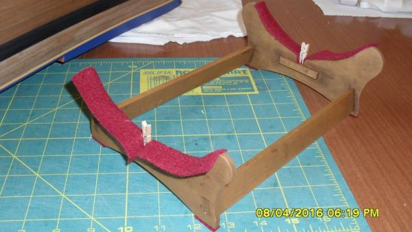
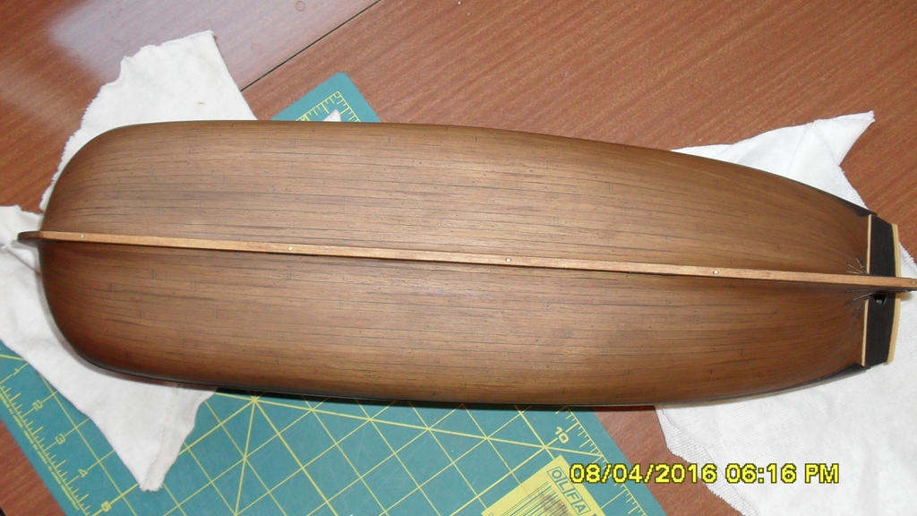
Having built the rudder I could fit the gudgeons and pintles to the stern and finish the hull below the whale with a second coat of matt poly. The gudgeons and pintles needed some filing to fit the brass straps and allow for an easy fit and removal of the rudder which I will be doing a lot of. I've also shaped the stand so the hull sits level and plumb and glued some strips of old felted wool to it. I've placed wooden locator pins from off cuts that push up into 1mm holes I've drilled into the false keel so I can easily remove and relocate the hull. later I might make a clamping system to hold the hull more permanently on the stand.
I've now jumped ahead and started making the deck furniture which I need to dry fit on the deck to find their final locations and finalize the deck beam positions. I've managed to pencil the centres of some of these deck beams aft of the mizen so this could take a while. Once I've got this done and inked the trennels and butts and give the deck a final poly, then I can add the hull fittings above the wale.


- Captain Slog, Matrim, rvchima and 7 others
-
10
-
Seems to be problems with posting links Robin as I can open these but some others from other peoples posts I can't. Not sure what the answer is?
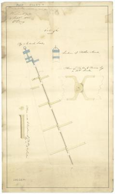
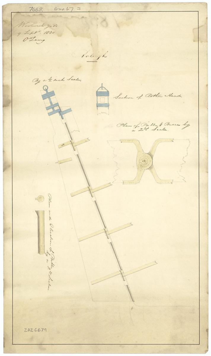
So here is a technical drawing of a rudder from Greenwich Museum I was going to post a link to but will upload instead. It's dated 1830 and looks like it's indicating the different types of metal, but that could just be my interpretation. Also of particular interest is the ring on top of the head, could this have been to attach tensioning tackle to the tiller arm?
-
I think it might depend on where the metal is used as to what alloy was used, whether iron or brass or copper if you read through this museum documentation of the 1791 wreck of HMS Pandora.I was qwereing steel being used .was steel used may be I am wrong robin
And in conjunction with the above artical the following artical gives the history of iron and it's uses on ships from the 1600's. It appears from this artical that iron smelting wasn't refined until the 1800's and up until that time it could be quite brittle.
-
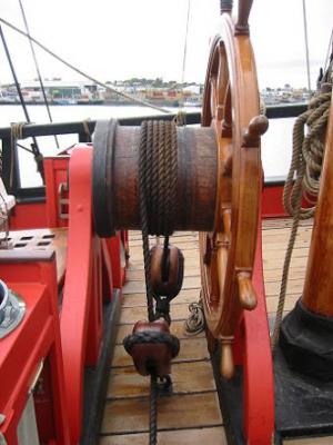
For clarification of what we are reffering to, then please read posts 14, 90, 91, 98, 99 and 100 while referring to the following link to a photo of HMB Endeavour replica's tiller housing showing the metal work I am refering to that is attached to the top of the tiller and which runs up into the housing which we have just established are not the iron tiller braces that needed repair in Cooks log. http://www.modelships.de/Museums_and_replicas/Endeavour/gIMGP3613.jpg
-
Thanks Druxey. We might have made some progress today as it looks like we can rule out Cook's log as referring to that piece of steel on the replica which is bolted to the top of the tiller and passes up at an angle to under the rudder head housing. Still like to know what is hidden under that housing?
So the probability of using tackle to hold the tiller into the rudder head and an arced tiller support under the tiller as was done for tillers of this size still stands and is reinforced by the clarification of what those "Tiller braces" likely were that Cook repaired, unless evidence to the contrary comes to light.
-
Steve: Thanks for this information and I stand corrected regarding the Armourer’s Forge and the Naval title for Blacksmith which I didn't know and hadn't come across this version of Cook's log. I see that Robert Taylor is listed as the Armourer on board the Bark Endeavour. Looking ahead in Cook's log from the link you provided I found this:
Wednesday, 25th. Winds and weather as Yesterday. P.M. set up the Armourer’s Forge to repair the Tiller braces, they being broke. By night we had got on board 12 Tons of Water and two or 3 Boats’ loads of Wood, and this I looked upon to be a good day’s work. The Natives gave us not the least disturbance, but brought us now and then different sorts of Fish out to the Ship and Watering place, which we purchased of them with Cloth, beads, etc.
So Cook here clearly mentions "Tiller braces" which indicates at least two. So he is not referring to tackles like I thought, but neither is he referring to the single brace depicted on the replica because there is only one of these. So could he be referring to the steel strapping on the rudder head of which there are several and which are depicted in the photo's provided by Frankie?
Thanks Frankie for providing these photo's of rudder heads. I've already looked at these and they do not have the metal tiller brace that I'm referring to which is in photo's of the replica, however yes they are reinforced with steel strapping as tiller heads of this era were and which in light of my recent discovery in Cook's log could have been the braces Cook needed to repair as I've indicated above. Unfortunately the tillers do not appear to be 8" square by 18 feet long from the head, but instead appear considerably shorter and smaller, looking to be only 4" square judging by the people's hands holding on to them so the vessels are probably also relatively smaller than the Bark Endeavour. In this case the forces involved would have been far less, about 1/4 less by my reckoning when compared to the forces in the rudder head from Endeavours tiller arm if it was unsupported.
Cheers guys, this information is helpful.
-
Another point to consider:
Cooks HM Bark Endeavour crew list http://www2.sl.nsw.gov.au/banks/series_03/crew_01.cfm there is no mention of a black smith that I can find. Now if the tiller brace which broke twice in the rough seas off the coast of New Zealand that Cook refers to in his log were made of steel then they would have needed a black smith to repair it. This would have entailed building a make shift smelting fire on shore to weld the broken metal brace back together which I think would have been doable but not likely with out a smithy.
Further having a past life as a industrial maintenance technician I can tell you that you don't use a nail to replace a blown fuse wire because that weakness is a safety feature built into the circuit so it breaks at that controled point protecting the rest of the wiring and building from serious damage. This same principle is true for any mechanical system, so it dosn't make any practical or logical sense to attach the tiller arm to the rudderhead using a thick chunk of steel right at the point where there is almost 2 tons of canterleaver preassure inside the rudderhead caused by the weight of an unsupported heavy oak tiller.
The most practical solution I think would be to follow accepted practice proven and used at that time for over 100 or so years. That is to support a heavy tiller along it's length using a 'tiller sweep' or quadrant thereby instantly reducing the canterleaver stress in the tiller head from 2 tons to 0 leaving only the sheer stresses from steering for the rudder head to take. As for the tiller brace I think it would also have followed tried and true practice and as such more likely would have been block and tackle to hold the tiller in it's seat in the rudder head. Then if there was a sudden loading at this point the tackle would break like a fuse in an electrical circuit thereby protecting the tiller and rudderhead from catastrophic damage and requiring only a short stay in a harbour for repair as indicated in Cooks log. Also this method of tackle to brace tillers needed tensioning from time to time to maintain a good fit of the tiller to rudderhead which couldn't be done with a solid steel brace.
So until more evidence to the contrary comes to light I think the the red line drawn in one of the 1768 draughts indicating what could be thought of as a tiller brace going from the rudderhead down to the tiller would more likely be indicating the tiller brace tackle. But this is just my speculation based on historical research and technical experience. I am not an engineer so any figures technical figures given regarding canterleaver pressures need to be confirmed.
-
-
Jud is this correct: If I take an 18 foot beam and support it at a fulcrum point 'c' of 1 foot from end 'a' and apply 250 pounds at the other end 'b' then would it produce 1.9 tons of force at end 'a'?dasacat; Been close to 50 years since I studied force vectors and bending moments, there are probably others much more qualified to do the math than me but I will do a very rough go at it, it should show the types of forces acting on the top of the rudder post created by using an unsupported cantilevered steering tiller. The easy bending moment would be the iron fixture at the end, going to use a weight of 150 pounds and consider the force as acting on the end of the 16 foot section of the wood tiller. 16' X 150# = a 2400 ft lb bending moment at the rudder head.
To make it easy will consider the force acting on the cantilevered tiller from it's weight acting at the mid point of 8'. So the weight of the oak tiller being 280 pounds concentrated at the unsupported midpoint the moments would be, 8' X 280# = a 2240 ft lb bending moment at the rudder head. Add those forces up, 2400 ft lbs + 2240 ft lbs = 4640 ft lbs of bending moment acting on the rudder post head, that way for the same reason we put long handles on wrenches.
What I did here is only a limited and rough calculation of the forces involved, it includes assumptions about where and what forces are involved but it should indicate the value of having support for the tiller. The modern replica may be using lighter and stronger materials, what is under the rudder post cover is unknown. Materials may change and lightening the load but the directions of the force vectors involved have not.
Keep in mind that my statics and strength of materials is very rusty and I'm not an Engineer.
jud

Assuming I've understood the physics, then the 8" square oak tiller would need to be able to withstand a load of 1.9 tons at the fulcrum where it enters the rudderhead. Whilst the rudder head would need to be able to withstand an upward load of 1.9 tons @ 1 foot past the tiller fulcrum while at rest. If this is correct then we need to know two things. What is the breaking point of an 8x8" oak beam and the steel strapping required to lift 1.9 tons. If the breaking point of the oak tiller is less than 1.9 tons then it needs to be braced with a support along it's length. If it can withstand a breaking point of 1.9 tons plus extra for tolerences then the rudderhead needs to be strong enough to hold past an upward load of more than 1.9 tons.
Of course please correct me if I've got the physics wrong.
Bottom line is regardless of the conventional interpretation of history and what we might choose to believe, as Jud has rightly stated, "everything still needs to obey the laws of physics", which is what we are trying to research and answer here with out bias.
-
-
While waiting for a reply to the email I have been wondering how to proceed with my build. I've decided that on my build log (not here in this discussion) I will attempt to build both helm rigs in a way that I can perform a simple refit should new information necessitate it.
I've also been looking at the tiller brace that runs from the tiller to the rudder head and need to ask this question if anyone can please help. From this research I'm noticing that in all the old tiller plans I've seen, all the heavy tillers can be readily removed by means of a pin through the end of the tiller or tackle from the tiller to hooks through 0 rings in the head. So if it is a solid metal bracket on the Endeavour then, would I be correct in speculating that it could only be bolted to either the tiller or head but not both. Meaning would one end need to be pinned or lashed some how to enable the ready removal of the tiller in an emergency?
-
Jud I'm really appreciating your technical input into helping answer these questions and as far as I'm concerned your engineering expertise is way above my pay grade so I'm learning a lot from this discussion. As far as your education is concerned I think that puts you in good company as I believe Einstein was also a High School drop out, plus I have difficulty with communication too which has gotten me in a lot of strife over the years so I think I know where you are coming from in this regard.
Regarding the replica I have sent them an email with several technical questions concerning the helm and tiller that we would like to know the answers too. I don't know when or if I might get a reply.
In the meantime I'm searching methods of holding the tiller in the rudder head. If we use a tiller sweep then this would affect the design purpose of what appears to be a bracket going from the tiller up to the rudder head as shown in the proposed plans of 1768 but which I'm not seeing in the 'as refitted' plan of 1768 which might be due to only having access to a low resolution copy.
Also if the tiller sweep were used on the quarterdeck then I'd imagine it would be the reverse design for under the deck where the tiller hangs by a 'gooseneck' from the sweep. So on the underside of the tiller I'd imagine there would be a projection with a curved steel plate that rode along the top of the sweep with possibly a lip on it's aft section to help brace the tiller. The sweep could possibly be made of oak 1' high with a greased steel runner on the top like Jud has suggested. The quarterdeck beams appear to have been placed in the correct position to support all this. This of course is just speculation based on my current novice understanding of the physics at hand.
-
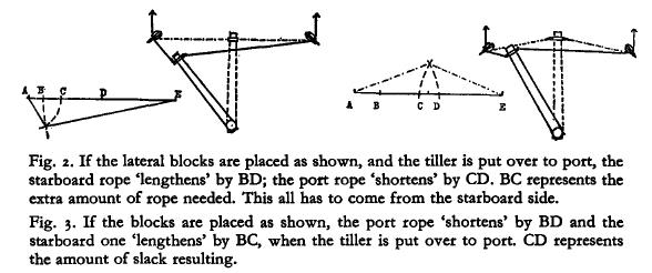
Frankie thanks for your input but if you look back over previous posts you will find that we have already tried that as part of 'working the problem' and it didn't work because of the chimney cowl. The working configeration now I believe is a lashing at the tiller head to tension the helm rope which leads to blocks positioned on the bulwarks to reduce slack and aviod the chimeney cowl, which then lead back through blocks to the wheel like on the replica. We have been using a tried and true formula for working out the slack in any given configeration and thanks to Jud's efforts on the cad I think we have don't that. Also your idea of more turns on the drum to take up slack won't work because the rope is nailed on the drum fixing a centre point for the closed loop formed by the helm rope, so the only way that I know they used to take up slack at the drum caused by the tiller arc, was to increase the diameter of the drum relative to where in the tiller arc the slack is produced. As I indicated earlier this was done by making the drum concave but I understand we don't need to do that in this situation. The year is 1768 and chances are the rope is rough hemp although I think they also experiemented with raw hide but I can't remember when.
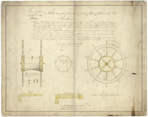
According Jud (please correct me if I've got this wrong) the physics of a 21 foot 280 pound plus solid oak and iron headed tiller projecting 19 feet from the rudder head, unsupported would break the rudder head. History tells us that it was common practice to use an arced tiller support (sweep) 2/3rds of the tiller wood length from the rudder head as indicated on the 1771 drawing in my first post, to support heavy tillers on vessels that required a wheeled helm configuration. We don't know what the replica tiller is made from so until we do we can't use that as a working example for 1768 which I've indicated in previous posts.


HM Bark Endeavour by dashi - Caldercraft - scale 1:64 - 1768-71 - bashed kit
in - Kit build logs for subjects built from 1751 - 1800
Posted
Thanks Paul and Pat for the ideas and suggestions re those hinges. I'm still undecided as to how I will make my hatch lids but leaning toward hinged lids that slightly overlap the coamings. I might even do this for the quarterdeck hatch instead of the sliding lid provided in the kit as I havn't found any evidence for these yet. I'm considering modifying some open lid hinges which there seems to be an over abundance of on the brass sheet to keep things uniform.
Further: the waist fore hatch looks to be an important access way and longer so as to admit gunners and sailors carrying stores into and from the hold and for the kitchen. So I'm imagining this will hinge along its length on the forward side and tie off against the gallows. I will try and stay mindful to keep this clear from the ships boats which seem to hog this area according to the kit plan. As to those boats I get the impression from the logs that two of them were towed as part of a navy trial into the effects of different anti fowling and anti worm hull coatings. Any ideas?