Jond
-
Posts
758 -
Joined
-
Last visited
Content Type
Profiles
Forums
Gallery
Events
Everything posted by Jond
-
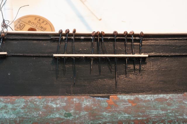
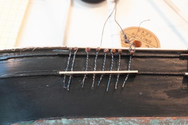
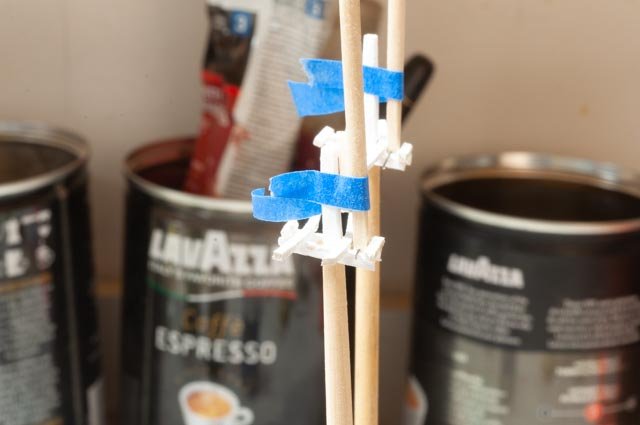
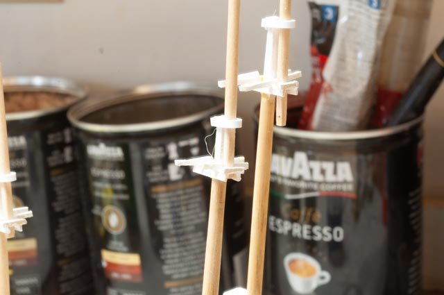
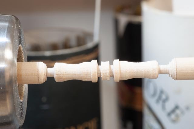
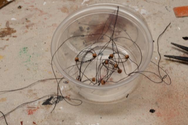
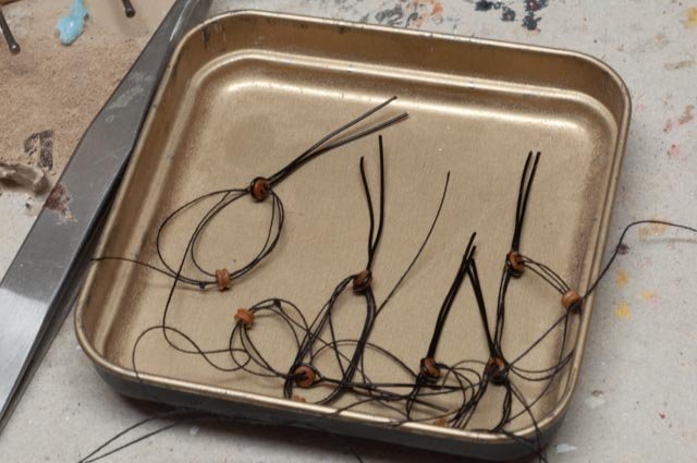
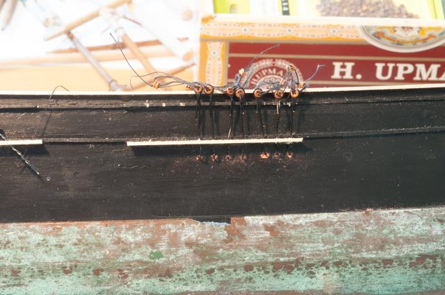
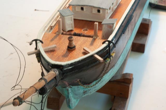
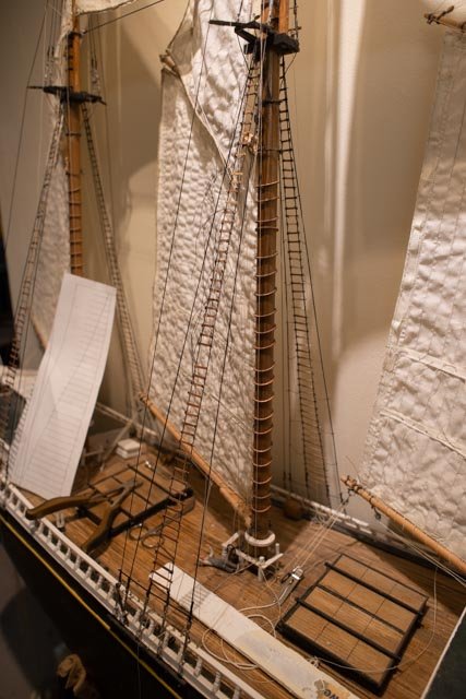
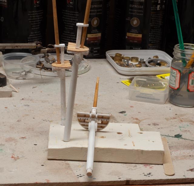
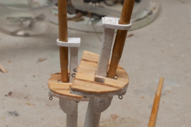
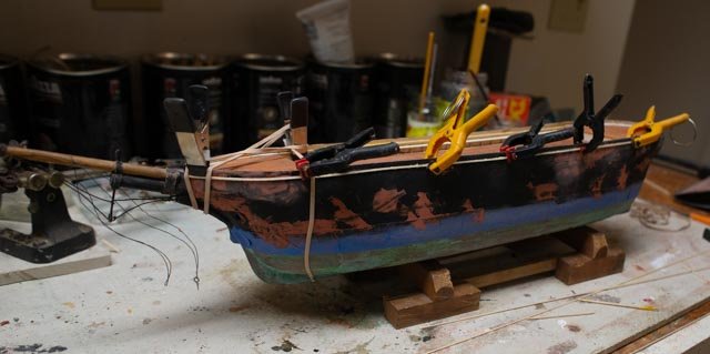
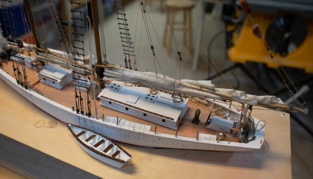
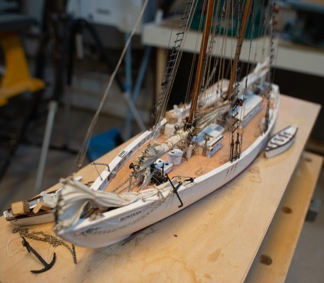
 Post 14 summer update Summer is on, and many things slow down our modeling process. A new sail boat, researching newer sails, regattas, and we all know the interference of yard work. I wanted to make at least one posting in July since a few discoveries are underway. I am sharing here some real trial and error events. This is the stage, I can say that after reading so many other logs, that I am supposed to finish the deck furnishings and make up the masts. All the time, we are preparing for the first lower mast step and shroud work. I have made a few steps, so let’s write them down. Ap87 this is an experiment for me. It is the first work I have done at this small scale. I tried using 26 gauge wire and twisting it. I see many others do this for eye bolts and the like. I don’t like the resulting look Ap-88 here I go up to 24-gauge wire and squeeze it around the 2.5 mil dead eye. I like the look and will go with it. Ap-89 The next challenge is to figure at what point do I sting the deadeyes. The issue is threading three holes through a 1/16” diameter dead eye requires holding the dead eye with something [ I used a tweezers], and after glue tipping the thread forcing it through. I do not see how I will ever do that if the deadeye is sitting with its back close to the hull…….we will come back to this issue Ap 90 time to set up for the topmast tops and the top gallant masts. The tops are delicate after trying some store-bought metal tops, but I have to drill 4 eye bolts into them. I find using the bendable styrene the easiest solution for me. I had bought several different sizes so I can experiment. Ap 91 here the styrene is in place and I drilled the holes through it for the eye bolts that go in next. Ap 92 here we are turning the windlass. It is fun to work on these parts. I am taking all the dimensions and details out of Crowther’s book. Ap 93 now back to the dilemma [ for me anyway] to thread the little dead eyes. This is my trial and error approach. I have selected the main lower mast to set first as it is in the middle. I am pre threading dead eyes in batches of 6. That number has to do with attention span. Ap 94 next I pre-fit chain plates and the lower hoop simulated with 24-gauge wire. Several of these ended up short so the next batches will be a little longer on one side. Ap-95 I have set 7 so far. I drilled little holes and bent the bottom into the hull. This will make them more stable when I start teasing the lashing to make them the right length. We’ll see if this method works. My logic is to work through 6 at a time of each step. After I have one mast ready, I will start splicing in one end of the wrapped shrouds and setting the height of the upper dead eye. there are other issues there too, so we shall see how this goes. Ap 96 here I have put a few of the on deck items in place. The windless will be tight to fit in as we recall the original main deck is just a 1/16 too high. Many more things going on, so the next update is likely in a month Cheers
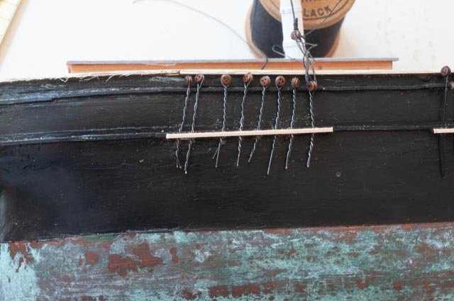
-
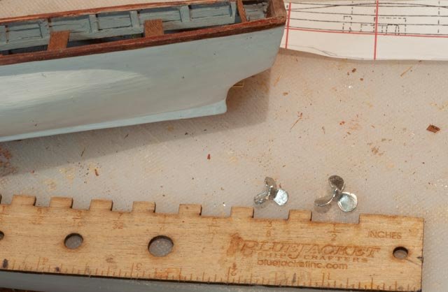
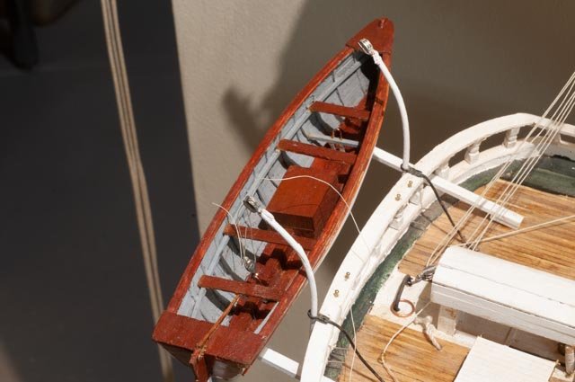
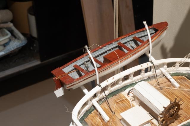
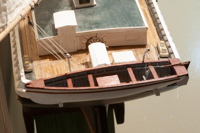
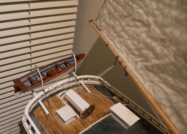
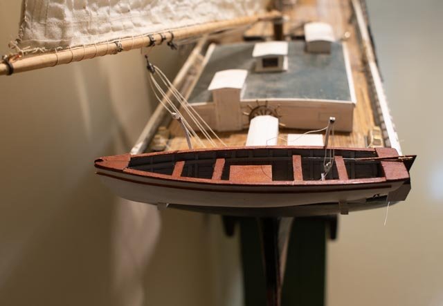
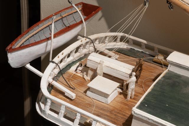
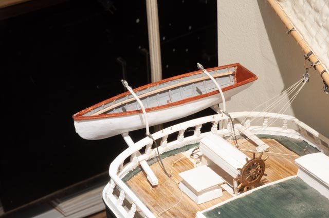
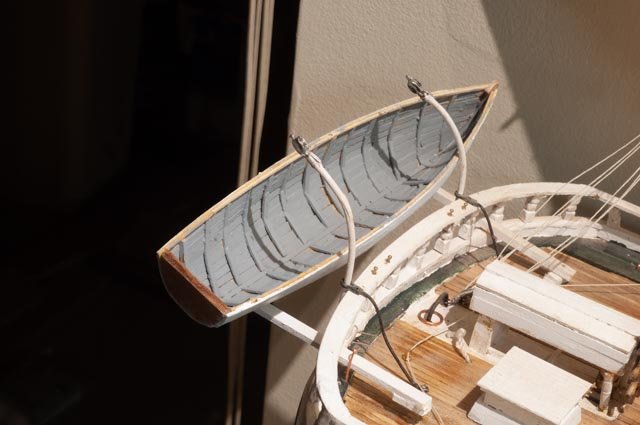
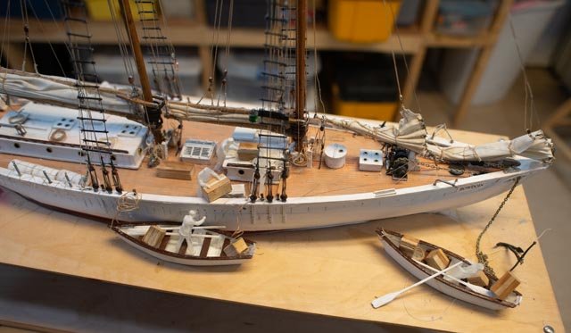
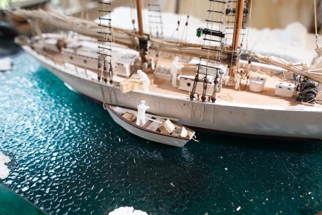
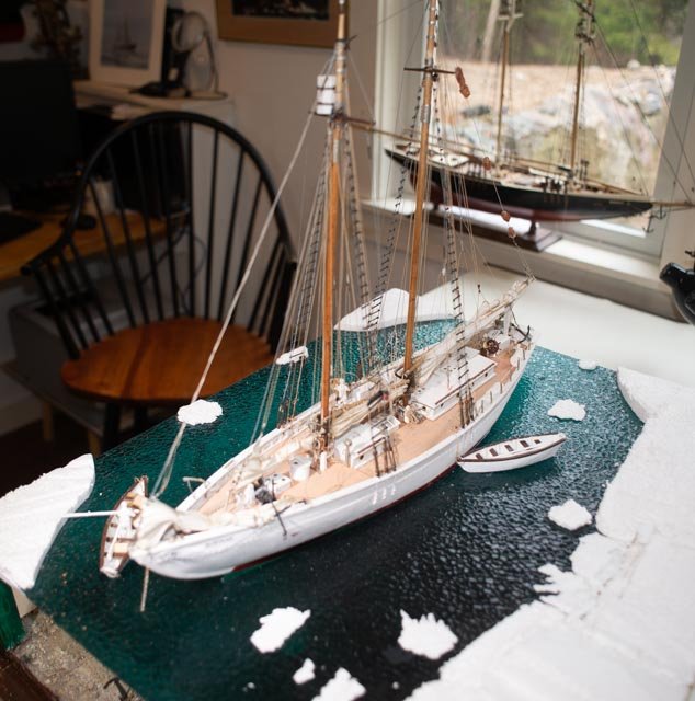
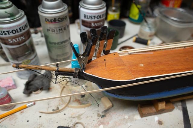
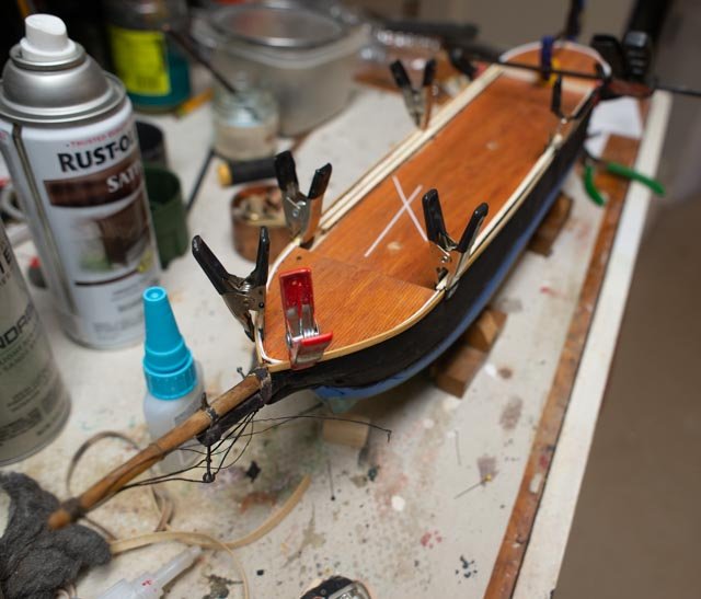
Complete the yawl boat Sometimes we have to say enough and stop working on something. Today that was the yawl boat. 23 I went back to my friends at Bluejacket and bought a bunch of stuff. Most was to build up supplies for the Aphrodite ship, but I got a few of their smallest propellers. Here I have ground it down to fit on the yawl boat. 24 here is the stopping point. I need to transport the schooner to a few sites this summer and there is no way to keep the yawl boat in place. Moving the schooner, the other day I broke off the strong backs. Yesterday I needed to remove a davit and broke it. Today I started rigging the blocks but if I do, I cannot remove the yawl boat. You can see the block engine cover and boxed shaft cover. I made up yokes and the little copper wire to hook the blocks to. 25 here we see where the davit lines and hull lashing will eventually be made off the taft rail pins. 26 here it seems obvious that the block and tackle make a difference, so I will rig them and have them at least in place. Lashing will wait till we are back home. 27 here we have the overview of the after deck and I feel this is better to have than the silly block and fake canvas i used last year. 28 I end with the view showing her sail away. It reminds me that I don’t have the name on the transom yet. We never really finish do we Cheers
-
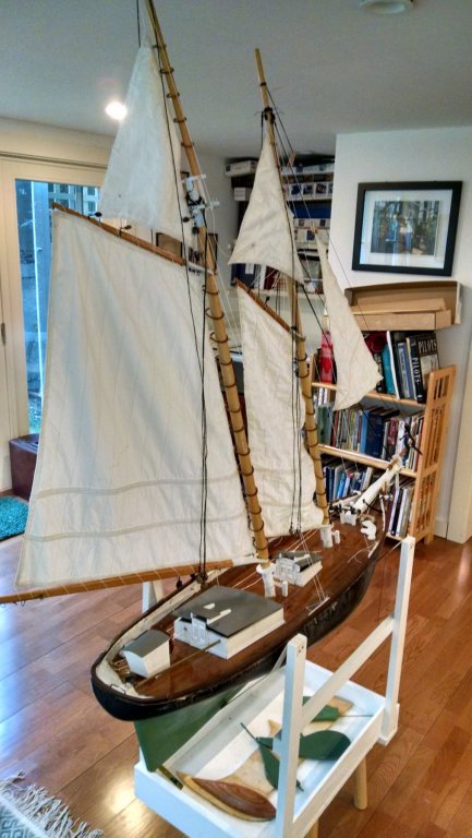
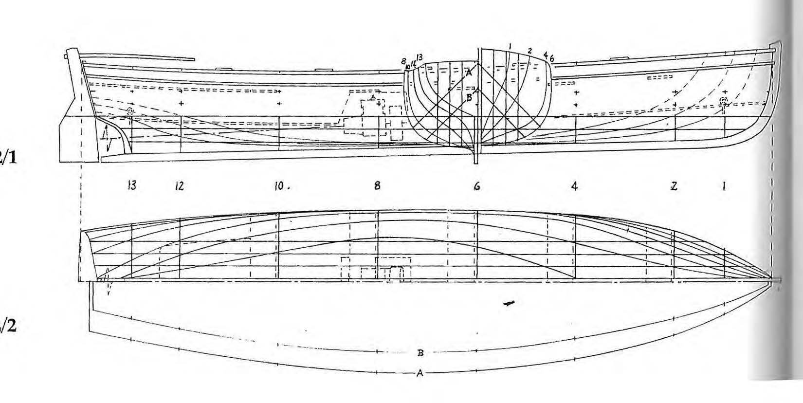
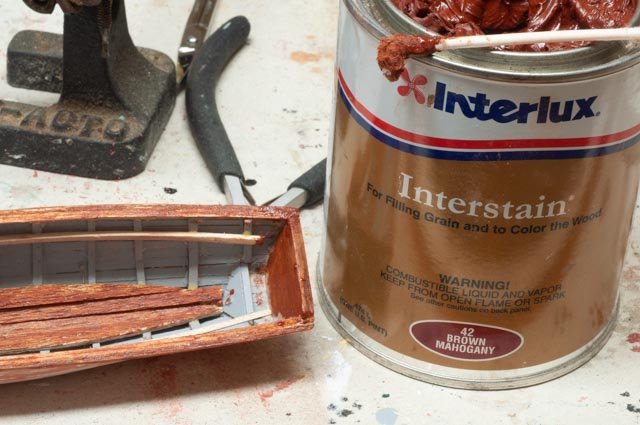
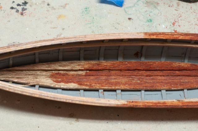
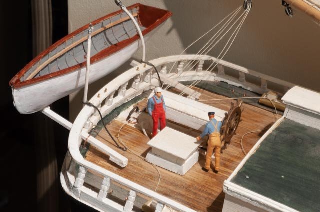
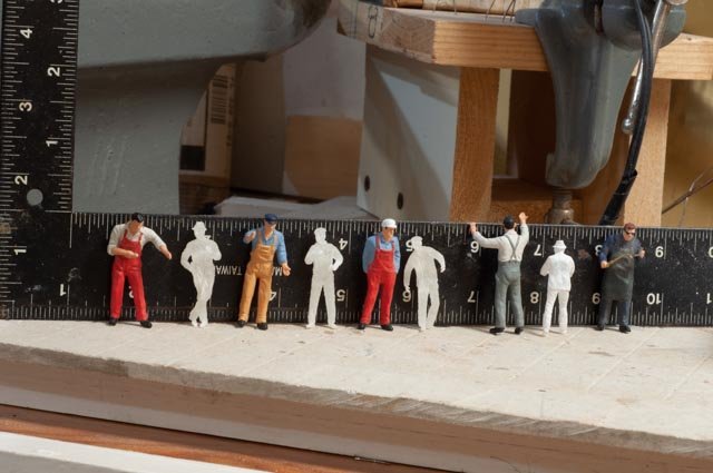
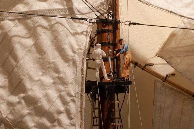
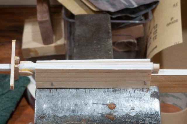
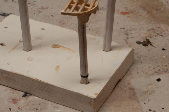
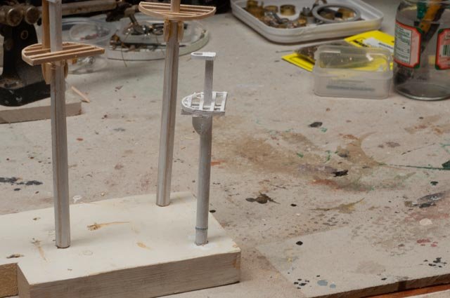
People sizing post A little more progress has been made on the yawl boat and a need to settle on figures, that is size of figures. I also need to give credit for the drawing in the last posting. The yawl boat design comes from the book Anatomy of the Bertha Downs. A great book for scratch schooner building. 16 when I was restoring my 78 year old real BHOD sailboat in 2015, I learned a trick of boat builders to match up the different mahogany wood colors. Mahogany bought in 1941[ likely from the Philippines for the combing is not necessarily the same as the piece I bought from Honduras [ via Rocklers] for new work. Intelux makes an “ Interstain” that brings out a rich color so we all look closer together. This can has been parked in my shop slowing drying out for nearly 5 years. I am Using cue tips to go to the scrap left over blocks form some old kit for the transom, to ripped planks from planks bought a few years ago for the model of my BHOD sailboat. 17 here we see a richness added to the planks that should help when the different mahogany blocks are added for the engine house Now to the figures. 18 Here we see two of my five-man crew that are used all through this build. I bought them online as O gauge railroad workers to be the same scale…1:48. Well funny story if you google O gauge it says they are 1:48……well hold that thought.... also these guys could row that yawl boat. 19 My son put me onto Shapeways the 3d printing folks to get crew for my 1:24 scale Bluenose. I went back to buy 1:48 figures from them to use in the Bowdoin Diorama. They are noticeably smaller than these O gauge guys, so I thought they may have shipped the wrong size. When I measured them, sure enough they were right on; standing up straight they get to 1.5 inches. 20 let’s line them up and see what we get. The O gauge guys are all 7 feet tall!!!! So check it out if you are using o gauge figures. Mine are all roughly 1.75 tall. I have been using them for years and oops many false images…oh well live and learn. 21 up in the rigging it looks like father and son 22 these properly sized figures change the whole concept of the yawl boats size. Fyi the seat clamp is maple…my first hard wood milled from scratch. Cheers
-
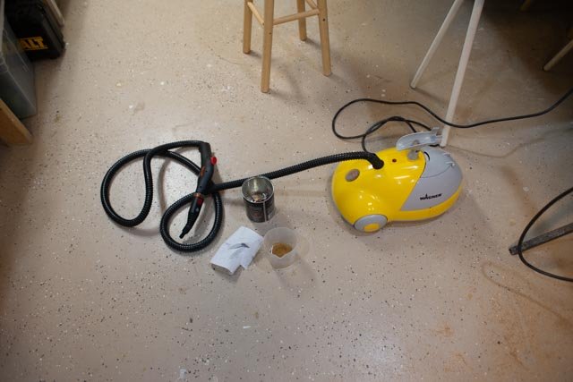
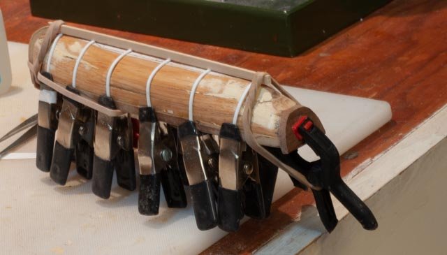
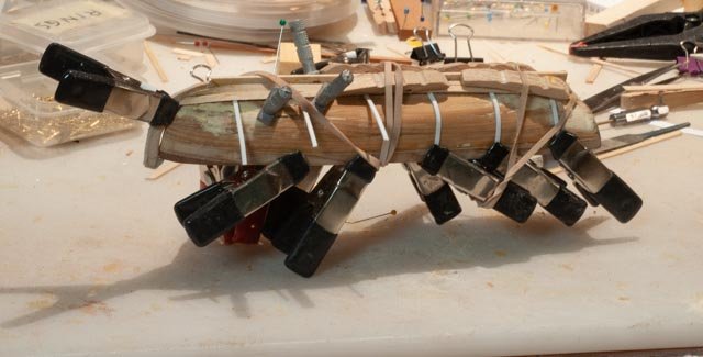
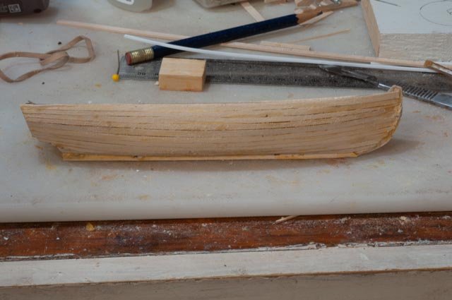
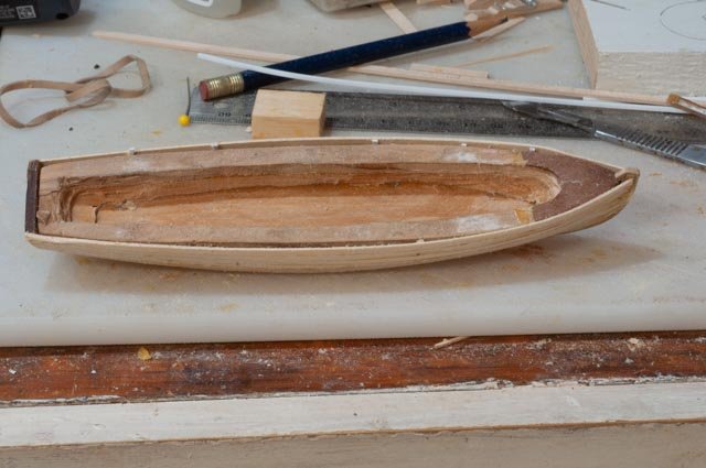
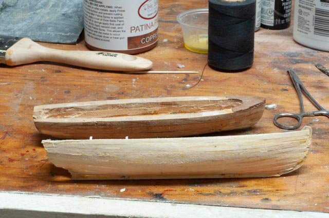
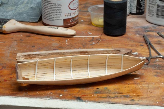
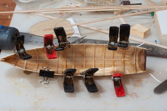
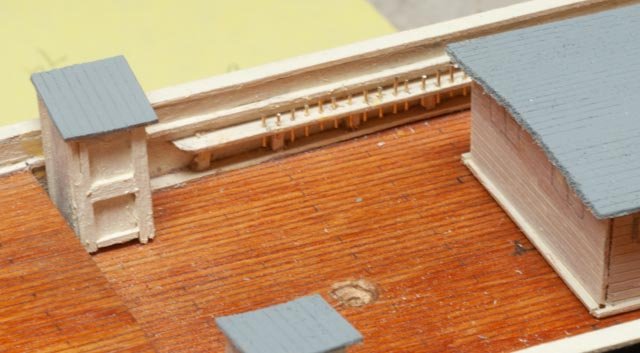
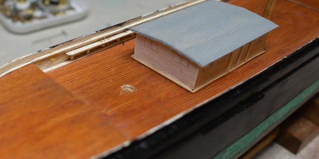
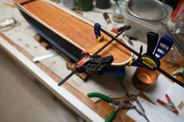
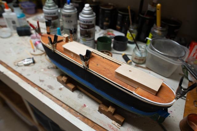
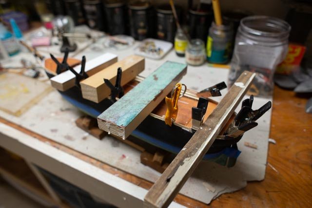
Post .................rebuild a yawl boat Ok I thought it is about time to record what has been going on as I only have a month to finish and give a few talks. I have been dividing my time between completing the Bowdoin diorama and getting it to the store museum....done. Fixing two schooners Bluenose and Herman Zwicker for the store....done. Aphrodite the first ship built here in Boothbay....mostly research and night reading of blogs with a little mast work on the side, and here. So far, the ratlines are sort of done. Cn19 5 I need to tie off the sides every 5th slat going up and the third tie offs for the center shroud on the fore mast. the yawl boat Up through the radio sailing effort on the original build, I made a plug with a fake canvas cover acting as the yawl boat. I have never seen a photo of a cover on a yawl boat, so now that Charlie is retired from sailing and supposed to focus on more detail, I have no excuse not to have a real yawl boat. A colleague at the local Downeast Shipmodeler’s Guild showed us one day a plug for a small Whitehall where he had routed out the interior of the plug so he could use normal clamps on the bent frames and then the freeboard portion of the planking. He also used hard wood for the frames and steam to bend them and maple planking… wow. that was a brainstorm for me. Cn19 6 here I tried taking some hard wood and steaming it in a can. really a failure and everything snapped. After three unsuccessful attempts to bend frame that tight using hardwood and boiling and such, I needed a solution to get going. Many great builders talk about how easy it is to bend maple and other hard woods. I am not there yet but am determined to get their soon. let’s follow my learner’s approach 7 first off what plans. There are a few to choose from and this one matches up with many of the photos. I put it into turbo cad and scaled it. I plotted the offsets for each 1\4 inch, then traced and mirrored lines so i could cut out 4 small sheets of plywood 8 here we see I made the plug using build up plywood so I could use the jig saw to cut the interior. It's covered with floor wax and I am using styrene strips that I will remove later for setting the planks away for the plug and be able to remove it. I will figure out how to bend the ribs in after I remove the plug. the transom is mahogany and the keel and stem for the last time in my career are bass wood. 9 here I remain the amateur using basswood for planking. During this process I was milling my first ever pear for the fairlead planks on the mast tops of Aphrodite. Wow so different. I also milled down some maple and will use it in the finishing. I think I might put a thickness sander on my Santa list. I know I need mahogany for the engine house, gunnels, seats and transom, so maybe this is a transition for me. This hull is painted and smooth outside and painted gray inside, so I am still with basswood. 10 here is the top plank. Looks like putty again but my spilling worked out better than before. Maybe three of four more boats and some better wood and I’ll get it . 11 this top view shows the challenge to get the plug out. There was some convincing and scalpel work, but nothing broke 12 hurray we are separated 13 here we see the inside after separation. the styrene ribs come out and wood goes in. 14and here we have ribs in. and yes, I used ammonia water and bass wood and they are not perfect. I have a few larger frames as they hold the motor box. That was a guess on my part. It is the problem of being a retired engineer. There will be a floor covering the bottom too. The dot on the triangle was a bad attempt to layout the hole foe the shaft. When drilled for the outside it was a bit lower. 15 here we are with gray prime coat all over. I just wanted to see if we fit. Now it's time to start building the interior and cleaning up the exterior hull. Cheers

-
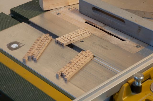
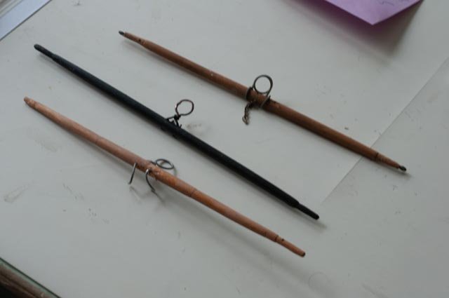
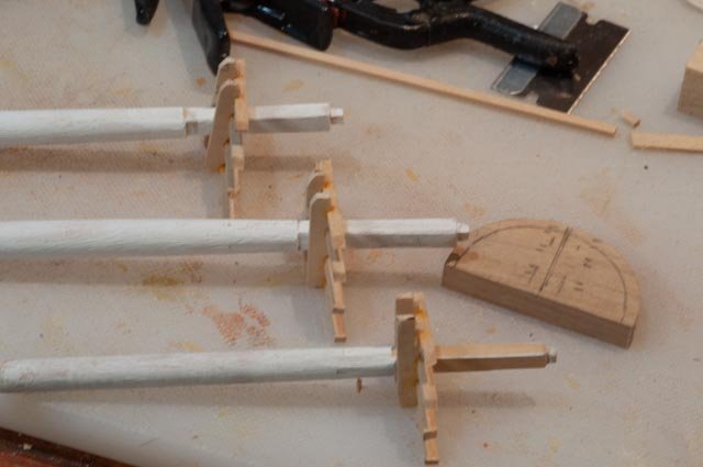
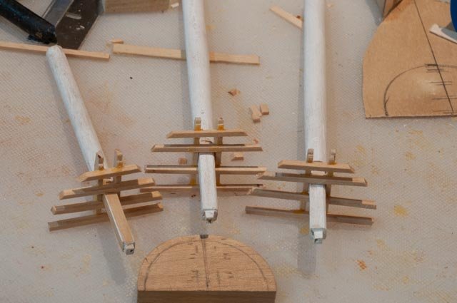
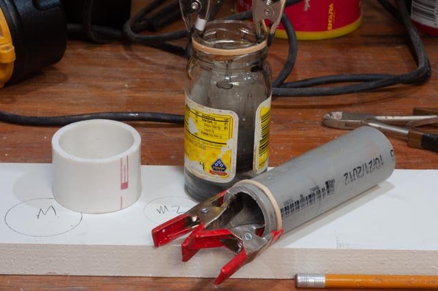
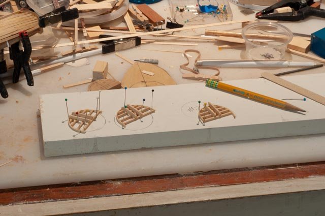
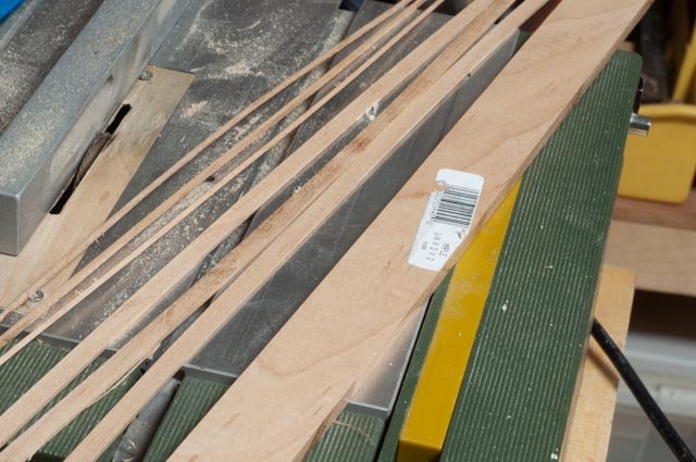
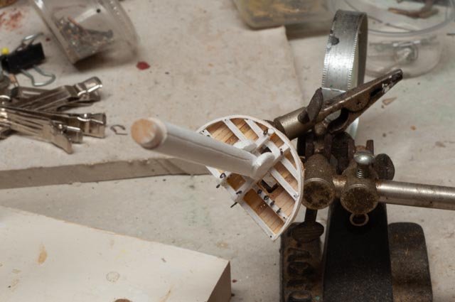
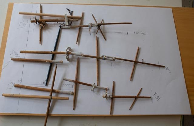
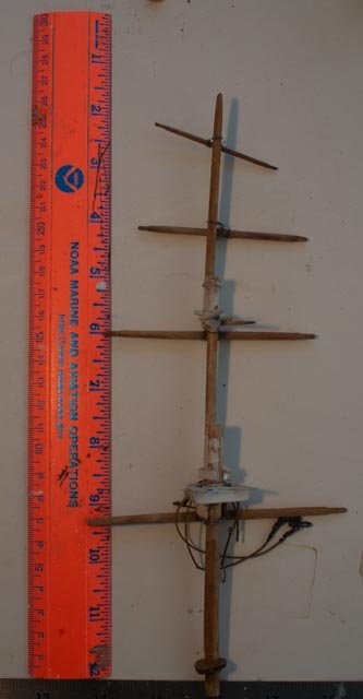
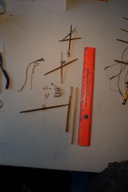
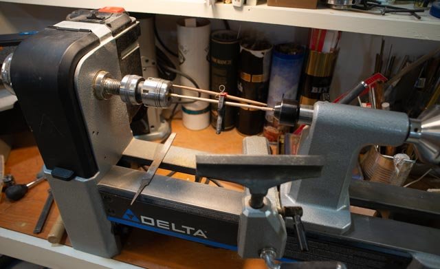
post 12 Lower masts and tops more details to figure out after much study I needed to get back to progress. In this post I went through building the three lower masts and their tops. I learned some things but most important is the need to improve materials, especially wood. Up until now I have been a bass wood, dowels and some pine guy. To get rid of 'fuzzies' and lumpy out of scale wood I need to get into hard wood. It will come, but it seems to be a challenge. A friend gave me a piece of rough pear and I will use a tiny piece as we go through this. I can cut sown to 1/16 so far successfully. I just keep buying strips of 1/32 bass wood I am building a yawl boat for Charles Notman at this same time and there too I am suffering. I leave that discussion for next month when I complete that model and get ready for a showing and lecture. A few related details. Ap 74 Here I took little pins and manually cut the heads and points off and then tried to cut them in two. They were too small for me to file after. There are 198 belaying pins on this ship so I thought it was worth a try. They are not glued in, so I can decide if I want to try again to file off the ends or use the 3/16 store bought pins from ModelShipways. I was thinking of trying to touch them with a file and then blackening them in place. Ap-75 Here we see three yards. The top is the fore lower yard from the model. The hardware is crude but functional. The lowest is broken main lower yard. In the middle I made up a yard for replacement. I made a similar crude fitting. So far, I don’t like it and will try to go with something more like the drawings. I will need some bands on the mast for this yard and the futtocks shrouds, and that makes the most sense. The masts Ap-76 here I have roughed out the doubling and hounds. The length is based on the Crothers calculations. He also gave details on the framing. Ap-77 here we see the sizing template. This was interesting as the figures say just over ½ the width but on the many examples that included dimensions it was always less. I settled on 12 feet for the two masts and 9 feet + for the mizzen. Ap-78 then one needs to find things in the shop to use to bend wet wood to get the rim. I read all about boiling and steaming from the real pros. I boiled and steams and broke many pieces and the went back to bass wood in ammonia water over night to get the pieces. It worked! Ap-79 here a compass and lines on pine allows pinning the pieces together. Ap-80 I made up this little gig to hold the masts to use a combination of razor saw and files to make the 4 groves in each mast to replicate the made up profiles. Ap-81 I used old 1960 vintage drafting tape we used in college architecture classes to make straight bold lines. [ no auto cad then] I have a box left over and a few are 1/16 black so they perfect model supplies. My plan is to paint it over as part of the mast paint which seems to be more common in artwork. Ap-82 here we see the first mast painted white. I think the painted tape works for the bands. Ap-83 here is my first attempt to mill my own hardwood. This is simple maple bought at Lowes. I also used the big table saw to cut a piece of elm to one inch by 1/8 and then cut a small strip to use for fairlead planks. Ap-84 Here we have the tops dressed out and planked over tops with the top mast loosely set in for looks. Ap-85 here we see the dark pear planks that is drilled. The real ships and more accurate model would have 33 holes stagger drilled on this plank. I simply drilled 13 holes so I can run perhaps toping lines through if I get that far. the caps are built up styrene. the tops remain loose so i can set them level with the raked masts. Ap-86 here we see the 14 eyes on each top. There are also predrilled holes for the futtocks shrouds that come next. In these last few close ups one sees the roughness of the filed and sanded dowels [ square tops] and the bass wood planking and beams. This is an area that needs more and more practice to get right. I am sure that the easy to use acrylic craft paints also hurt. I used a little cherry stain on the top masts and just hand rub poly on the tops and over stain. I would love to get to milling 1/32 maple planks for this type work Cheers
-
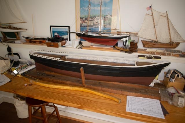
I am sitting here after three weeks of little wood work. I caught a cold and spent my many hours surfing building logs and more reading. I loved the new book Barons of the Sea a concise history of the owners, builders, and captains of the american clipper ship industry. I then did a lot of further reading and wow am i going down a rabbit hole. I read Ed Tosti's blog...wow such incredible study and workmanship. I am up to page 72 so a long way to go. I am also now reading other blogs and they are all taking my breath away. I just ordered Ed's first book, so at least I will have a great library. This is the 1:48 Flying Cloud that a friend brought over to get some help on fixing up. the model was built many years ago and is way off in scale as to bulkhead, pin rails etc. I am helping him get the masts and spars right, so next winter he can get those on. That project is how I got into Bradner's on line drawings. The owner is happy with simple dowels. I would spend days making made up and banded masts....crazy. My head is spinning...options. what is it I want to do. build large scale radio sail boats but keep them simple...I have one 50 inch Schooner I never finished plus a few Marblehead Vintage AMYA boats build large scale radio sail but put too much detail in them, so they are retired from sailing...I have two of these and in reality 4 including the 42 inch BHODs. build small scale like this build. My fingers and experience keep much detail from appearing. example that I am working on today.... things like the head cap. the real ones I have read were blocks of elm, maybe a foot thick by two feet and four feet long. what wood can replicate that at 1:96....... I have yet to graduate to milling my own pear etc. do I need to learn how to machine metal or cast . wow I am building up with styrene and super glue. we'll see do i try to slice the lower masts to be obvious buildups before banding? do I then put little plus under each band?..... there are 30 fairleads through the tops. Do I drill them? can you see them? I won't be rigging all those lines but even topping lifts for the yards need to go through them...... I could build a large hull like the one photographed here in a few months. I could then make parts like before. then however I have a another 7 foot model. the masts though could be real. I think I will just plod along knowing this is a real early learning curve. anyway I just want to record this mental process cheers
-
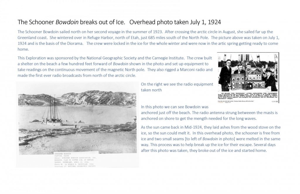
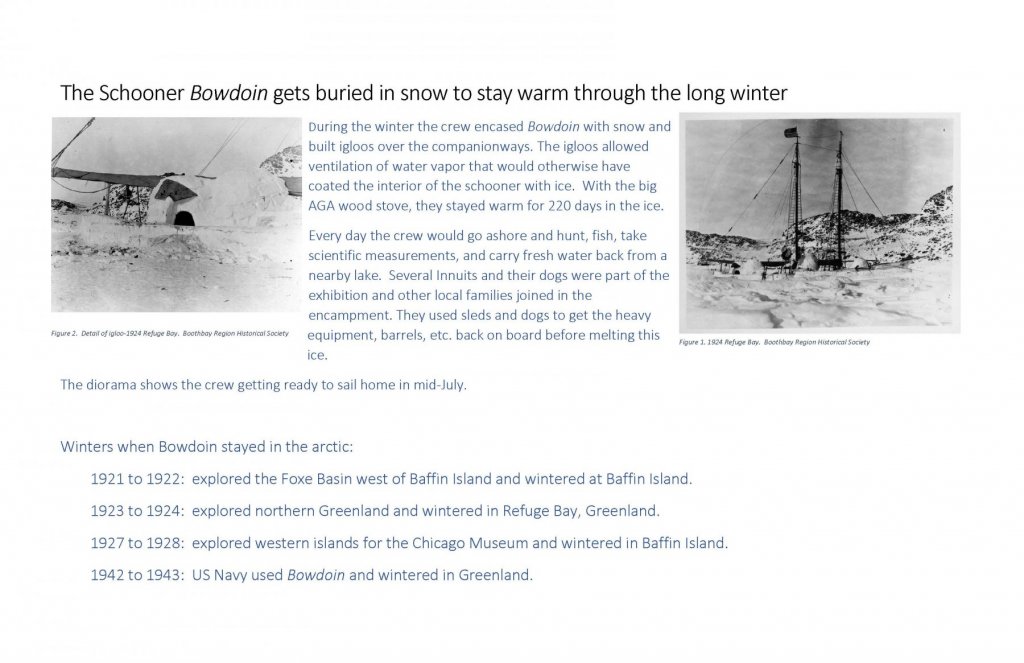
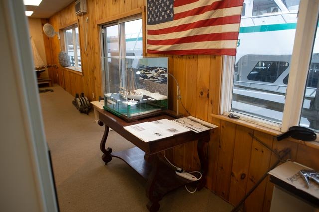
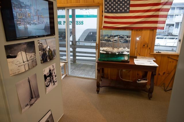
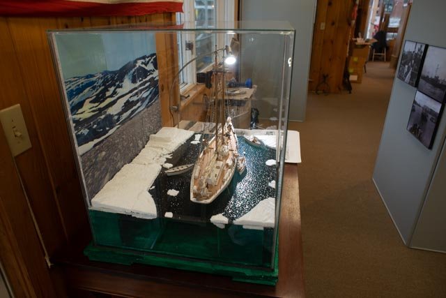
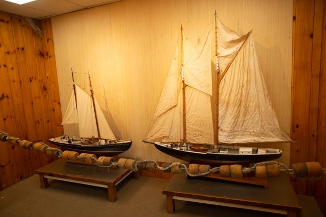
Post 39 The museum We finally made it. There is a lot more to do in set up, as Mark and Diane are two weeks from opening 316 a-d : these four pages are the draft for final editing and are to will be pasted on foam core as placards. They shall try to capture the story to go with the diorama, and will hang on a black cloth above the model[ where American flag is now] to help tell the story. 317 here we enter and see Bowdoin. The dock just out the window is where Bowdoin was tied up before leaving on several occasions. It is part of what makes this story so much fun 318 looking straight on one sees a kiosk where many visual items will tell of Macmillan and the trips north 319 even with all the ambient light I see enough of the sparkle on the water to be very satisfied with the experiment to use the small spot light as part of the display 320 This photo shows the two Canadian built Schooner models that I repaired for the show. The Bluenose on the right and the Herman Zwicker on the left. The Herman Zwicker was a resident of Boothbay Harbor for many years. She was often on display at Maine Maritime Museum. She is today in New York city and her sister schooner is on display in Lunenburg There are several other models and lots of good eats near by, so come visit us this summer Cheers


-
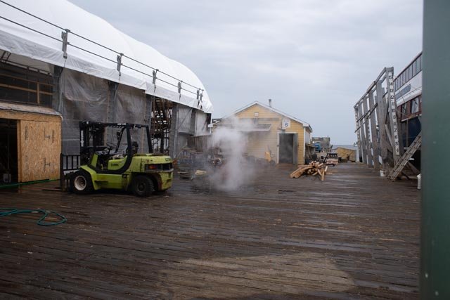
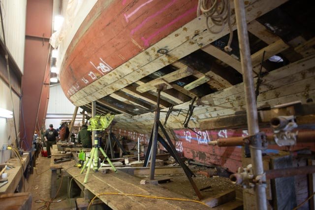
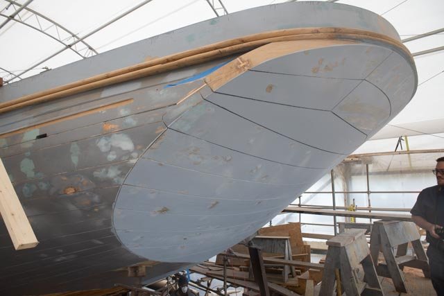
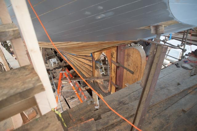
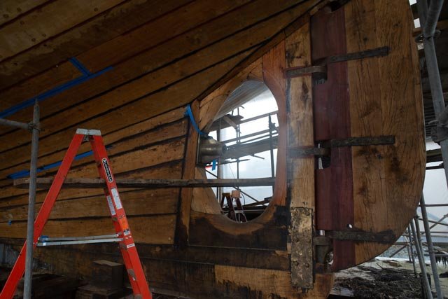
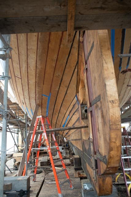
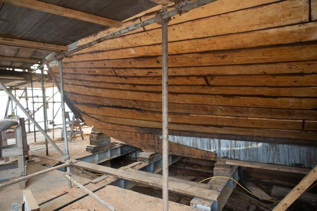
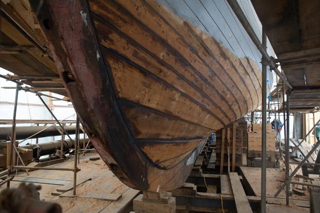
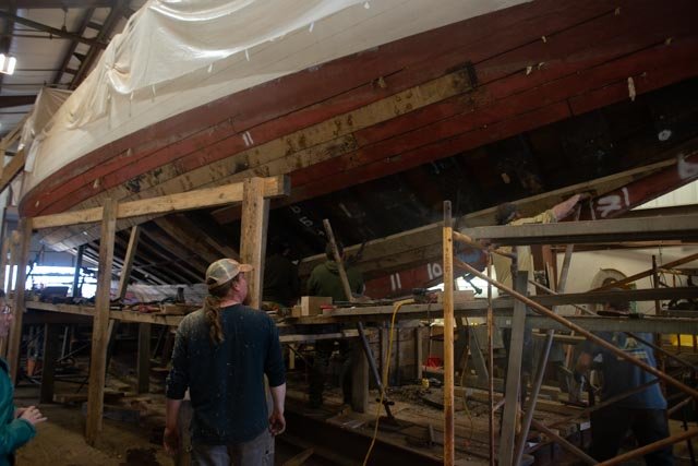
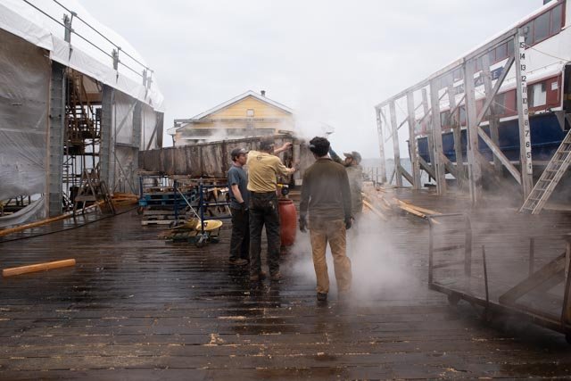
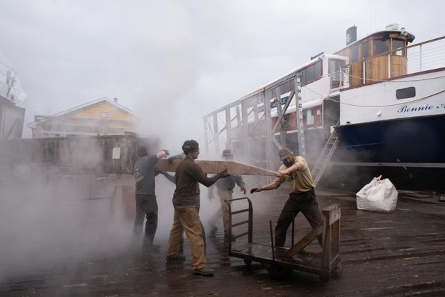
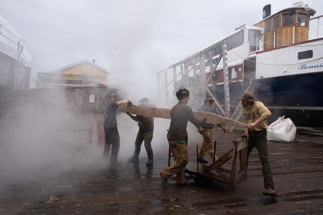
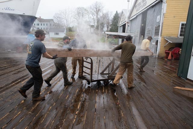
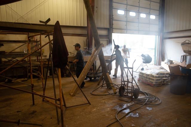
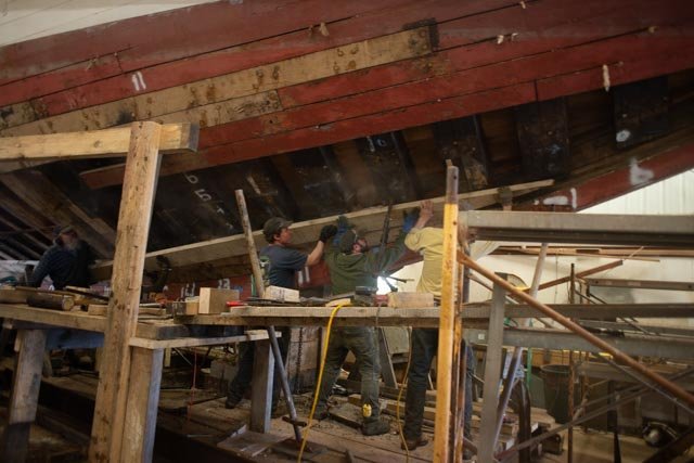
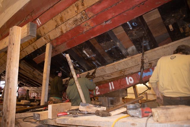
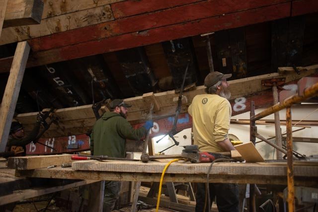
Post 38 Real Bowdoin gets planks 308 here I am on the dock in Boothbay Harbor where the real Bowdoin is getting her hull fixed up. The steam box is cooking the next plank. 309 as I turn around, we see the progress on the new planking. Some 40 frames were replaced and somewhere around 80 planks are being replaced The Ernestina Morrisey Before we see the new plank installed, we catch up on the Massachusetts state schooner also being completely rebuilt here in Boothbay. I share many pictures a few months ago. Today the final caulking is being installed before the hull gets painted. Here are come fun shots of the stern and bow 310 here we see the completed transom 311 looking down we see the progress working downward to get caulking in and prime paint on 312 how about the combination of craft skills to complete all of these components.it is wonderful to see these skills are alive and well. 313 just a fun photo looking forward 314 here we see the forward end of the lead keel and work up to the bow stem 315 this bow stem is African hard wood and one of the only pieces reused in the this rebuild. Back to Bowdoin…..it is time for the next plank. 315 a-h -Here is a quick sequence of taking the plank out and setting. They need to do more than one a day to get done and launched wow All for now
-
Thanks Nic I plan to visit you this year and will definitely see you in New Bedford. I am really interested in your cross section of the Morgan and am enjoying you Red Jacket build. I am currently rescuing and old model form Maine maritime and trying to replicate Aphrodite, the first of about 6 ships built in Boothbay. cheers
-
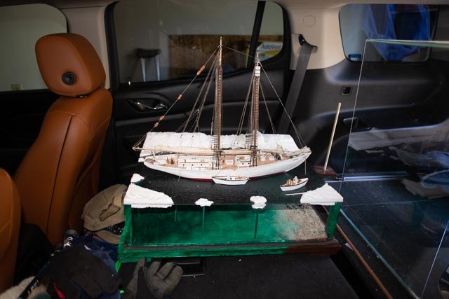
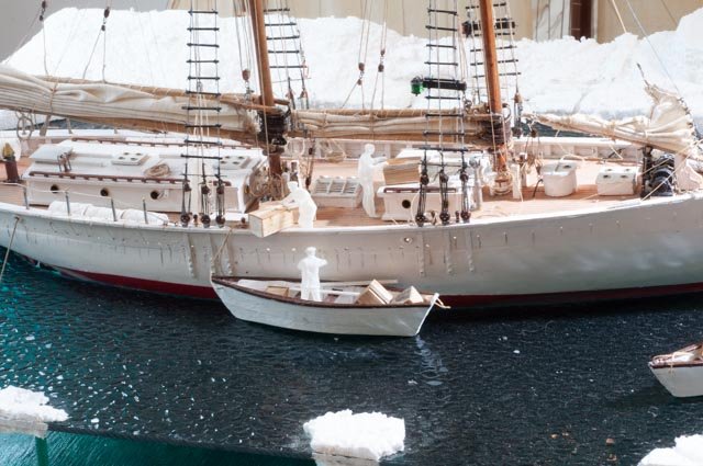
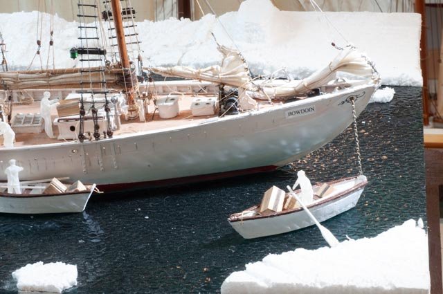
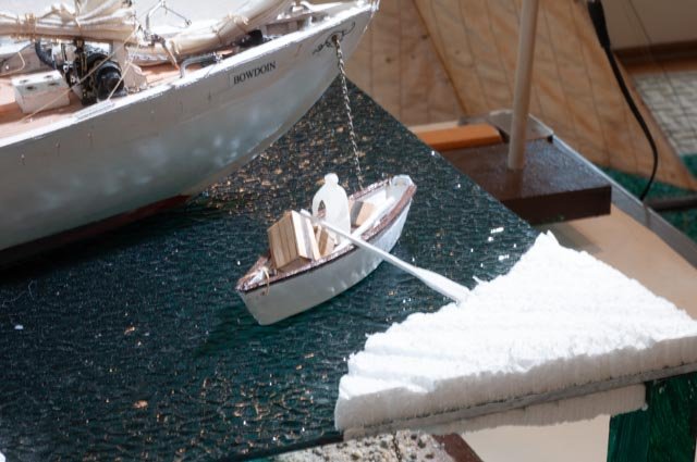
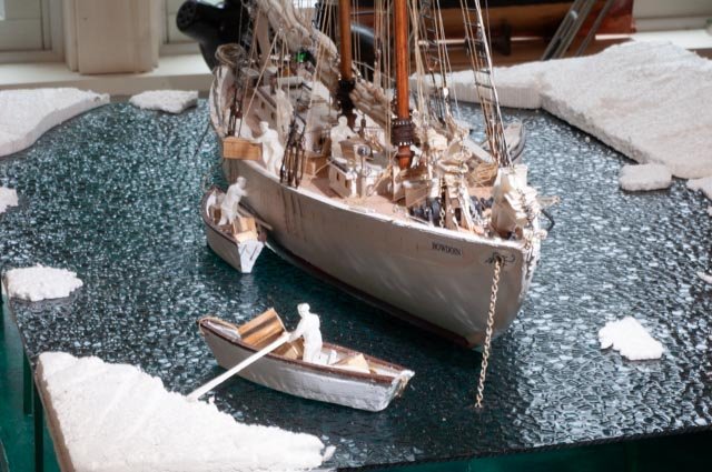
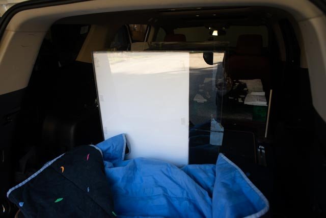
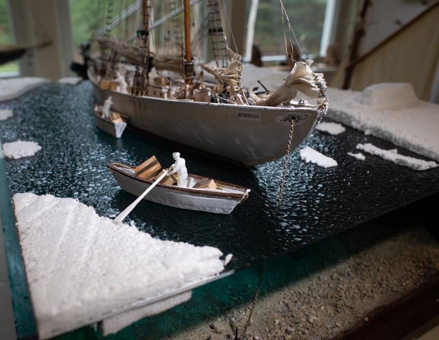
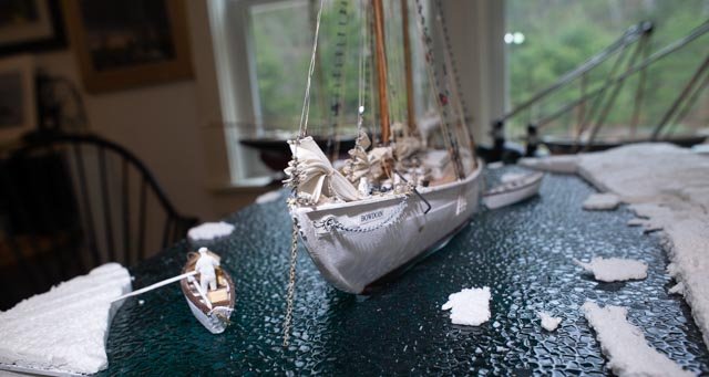
thank you guys for the thumbs up. we all know that is appreciated. here we are on our way to the museum store in Boothbay Harbor Post 37 We are ready to go 300 switching to the 90 mm lens to get some more detail. Our crew on board with the box needs to moved a bit forward. I suppose next time I need to cut out for dories too. 301 our waiting crew member finally stood up. A little white glue helped 302 I love the change in color of the water. I also have an extra anchor on the transom ready for use as they work their way out through the ice 303 here we are looking into the sun with the water sparkling 304 here we pick up and the sparkle fades and the shadows on the water stay. I like the sparkle reflection on the hull 305 looking down sun but lower to the water the water again comes alive……this fun though I really and just trying 306 glass box ion the car 307 Bowdoin in the car ready to go Cheers
-
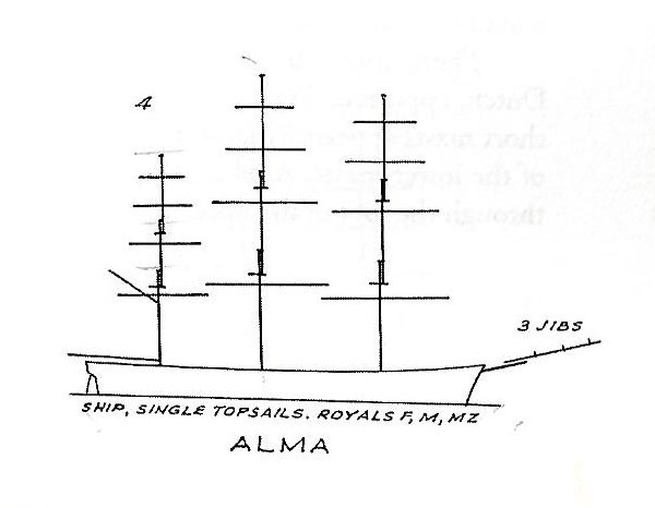
Post 11 More mast study….start to build I have been madly reading the Crothers books. I have also been scanning other builds of ships in this scale. Wow so much fun and so much to learn. I was thrilled to find others have picked up this masting information as well as other details I saw in these books. It suggests I may have fallen onto a good track reading these books. Anyway, I figured out my plan for the three lower masts so here I go. Foremast 1) Field measure of our model [ 147 foot} … 5.0” above deck with 1.125 doubling 2) Scaling off Crothers drawings of typical ship rigging plan including reference to Alma [ 153 foot]…5" above deck and 1.375 doubling. 3) New calculations based on the Crothers masting book….. a) [147’ length plus 30’ beam] /2 equals 88.5 feet total main mast. Then foremast = 8/9 of main=78.6. this is total mast, so we need to subtract the housing [ below weather deck] b) Ap-071 scaling from the Crothers cross section of two deck ship we get bottom of tenon. On the section it was conveniently 5 inches from the weather deck to bottom of keel and one inch up to bottom of tenon…thus 1:5. Measuring on the model the shear plank to bottom of keel is 3 inches, so the correction is almost 2-3/8 or 2.4 inches or roughly 19 feet. I would not pass a physics test with those measurements, but it is all about proportions. c) In the masting book, spar plan 51 is Alma, they show foremast to be 64 feet. Then we adjust. [ {153 ‘-147’}/2 =-3 feet as we are shorter than Alma. We subtract another 19 feet for the housing and have 64-3-19 =42 feet. 42/8=5.25 yippee ki yay or rather not bad, it almost agrees with our field measure and scaling of 5 inch. I plan to use 5.125 d) For the doubling we see in the notes that doubling was being reduced from .4 times top mast to .3 during this period. Looking at.3 x40-foot is 12 feet or 1.5” we find the scaled drawings from the earlier book we were 1.375”. for now, I am sitting on 1.375” [I did not want this to be greater than the mainmast] Main mast Same process. The model was 4.75 and 1.125 doubling. Scaled drawings and calculations supported 5.5 inches and 1.375…you will see as stated in the earlier measuring post that the top royal mast on this old model was 3/4 inch too tall, so this increase was expected. Mizzen Same process. The model was 4.36 and doubling 1 inch. The scale drawing and calculations both supported 4.5 and 1.125 doubling. I will reduce this to 4.0 length above the raised half poop deck. I have read the masts were typically made up and banded. The iron bands were spaced at 3 feet. The hounds were eight sided and ½ the length of the doubling. The doubling was square. Since they were 22 plus inches and the lower mast was banded, I assume these sections had bands, but I am still checking that one out. The whole mast was painted out. The lower yards were also painted out black. My plan is to now make up the three masts and lower yards and to check the bow sprit. While doing this I need to complete the cabins, pin rails and get ready to make other deck furniture and chain plates and lower mast tops. Cheers

-
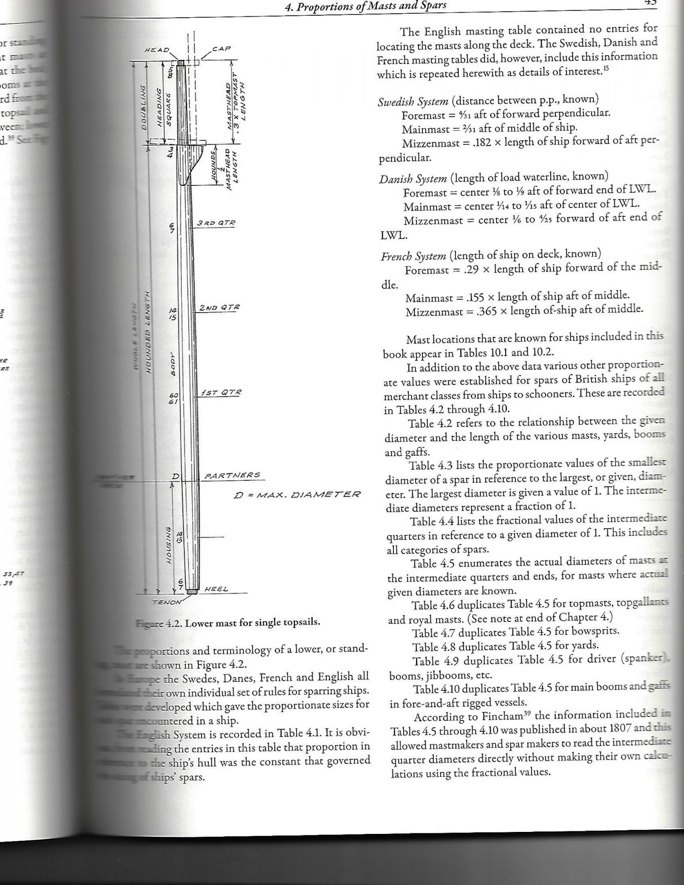
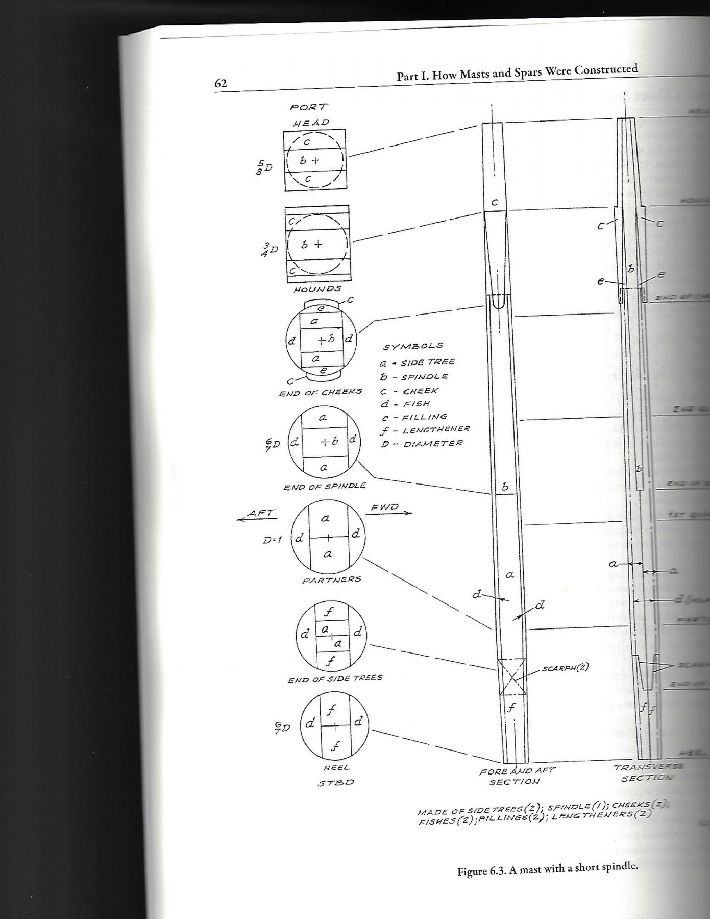
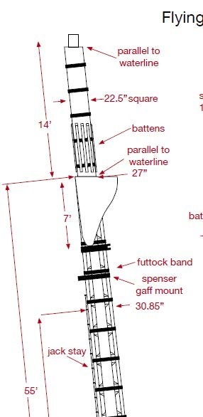
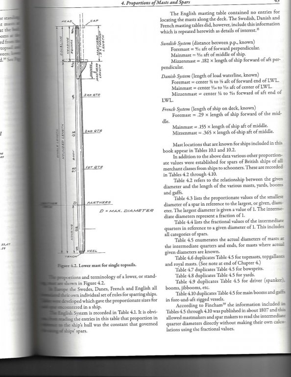
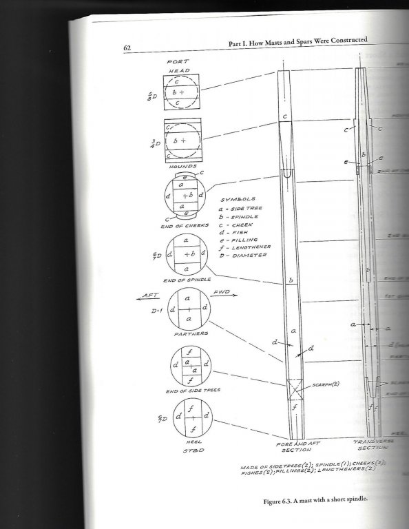
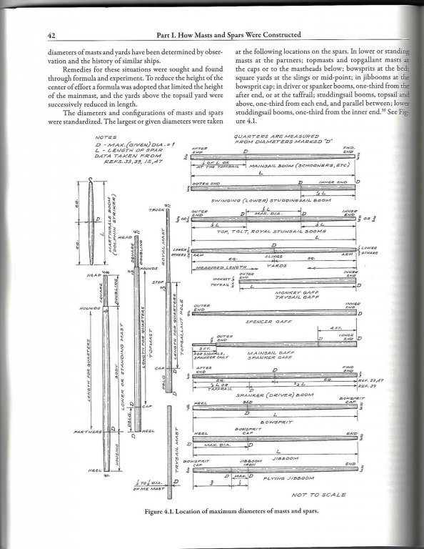
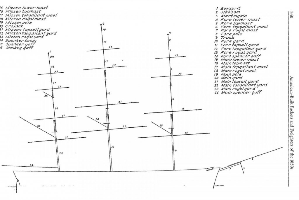
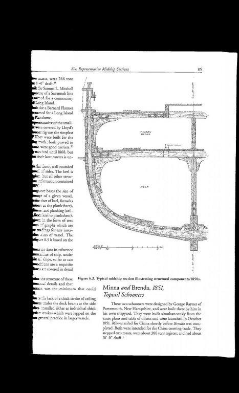
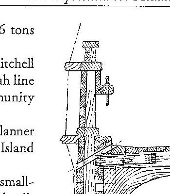
Post 10 Back to study of masts and yard 1850 ships One good thing about this build is the find of the great author William Crothers. Years ago I bought his clippership book and was awed. For this build I have bought the other two of his trilogy Ap 64 This book is amazing. It was reviewed in a post favorably and yes it costs $95 but as I said early, the hull was free. Everything I have done to date is based on the reading I continue to do in the this volume. Ap65 is a downloaded pdf from the internet of mast on the Flying Cloud by Bradner. Reading the notes, a bibliography came up and it was fun to go through. It lists not only the classic books but articles from both newspaper and NRJ. Bradner credits his details to three authors including Crothers and he cited another volume dedicated to mast construction. Ap66 here we are. Found it at Amazon. The third volume specifically on masts and spars. It is incredibly detailing and full of historical references and explanations on how things went together. A straight forward point that makes sense was that by 1850 the large trees that allowed single tree masts were mostly gone. Large masts and yard arms were being made of ‘sticks’ there is all kinds of information in this book. It seems that many were painted as in the cover painting and that squares with much marine art. I am still reading and gathering notes, but I believe in the end I shall replicate made up masts as they must have been the norm. As I recall in reading about the big schooners, large spars were floated in to Boothbay from Wiscassett. Much to learn Ap67 on this page from the Crothers mast book we see an example of the explanations. References to the tables completed the process and by matching the model to a relevant ship in a table [ our match is Alma from Sullivan Maine], we can be more confident of what we are building. There is interesting reading to come that I have not done yet explaining the calculations to establish the optimum heights of the masts and placement of the sails….as I said so much to learn Ap-068 here is one of several methods to make up a mast again from Crothers Ap-069 here is Crothers diagram discussing the maximum diameters and the locations of the tapers on masts and spars Ap070 here I have taken the masts apart, as I need to do this for rigging them one level at a time. I have already replaced the main lower mast and the broken yard. I have much to do before I get back to this and summer diversions are fast approaching. I believe I will choose built up lower masts, and they will be painted. I definitely will square up the heads and rebuild the cross trees. overall work I have just glued on the monkey rails and will try to get the hull cleaned up, pins installed and houses in before summer break. I will putter along reading and planning out the spars. Then depending on summer availability try to get them adjusted or remade. Fortunately, the deadline for this build is next year at this time, so all is good and we can slow down. Cheers jon
-
Post 9 Finishing the upper waste shear planks and channels This step is to do the best I can with the pig’s ear old hull and decide to move on. There is also a funny oops. I need to complete the exterior shear planks and channels over the finally repaired hull. ap-58 here again I am soaking and bending thin strips to shape the outer edge of the main rail plank. At this small scale I am not attempting to have a groove. This step included three more passes of putty sand paint sand putty sand …it must be me as new pin holes kept showing up. I think not being able to use the spray filler primer, which fills in things like pin holes is one of my issues. I also don’t have a paint station, so I am brushing paint. I know I need to get over that, and go learn how to spray with a new toy or two. maybe next year? . ap-59 Here is the shear plank bending to shape. ap-60 Here we have the oops. Back in post 4 I was proudly copying the chnanels from the original model. The were 1/8 by 1/8 ……omg…that means a foot square channel???. Here I quickly made up planks to agree with the Crothers detail and we are on again. ap-61 Here I painted out using the satin finish to see how it looks and if the defects are reduced enough not to catch the eye. You can also see I have painted out the replacement yard satin black as per the Crothers note and I think for now I will stay with this look. The highlights of the channels I think are better than in the ink black. I will use the ink black for any iron work. Ap-62 here we see bow on. Ap-63 looking ahead we have 198 pins to install. I have taken small brass pins and cut them and tried them in the pin rail. I will need a rainy day to put all of them in. That is not a commitment to add 198 lines, however. i also chose a soft gray for the roofs. there are no notes on that point. the Alma was shown to have pearl and I am using ivory for the bulkhead and later on the house after making many little windows. Cheers
-
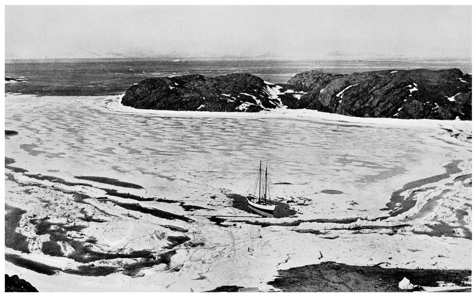
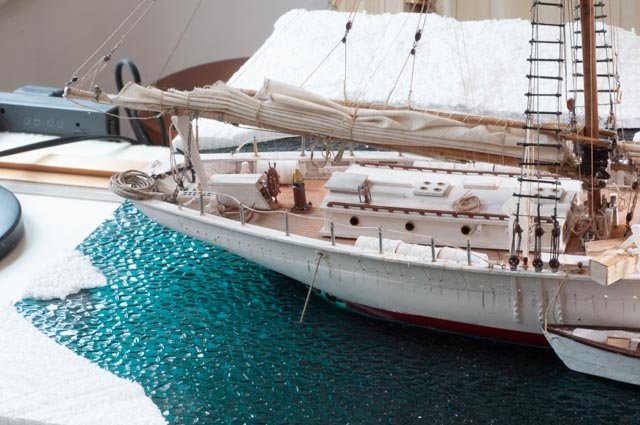
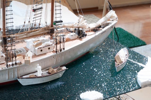
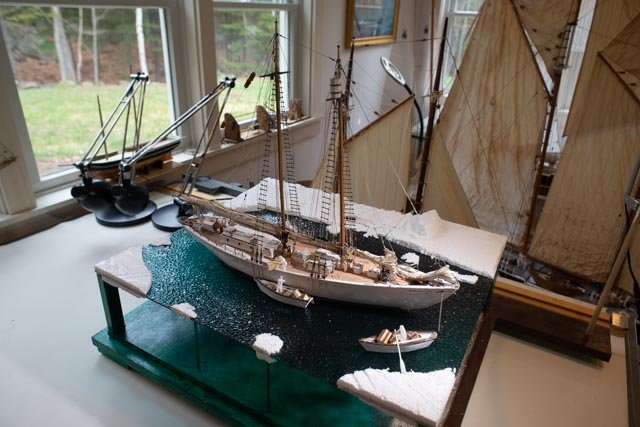
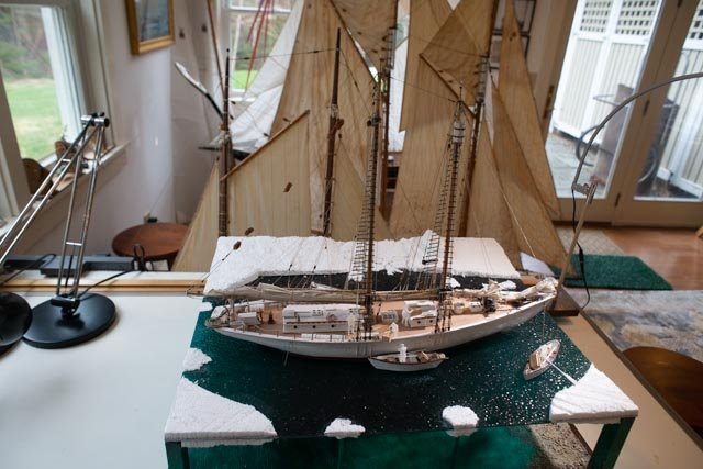
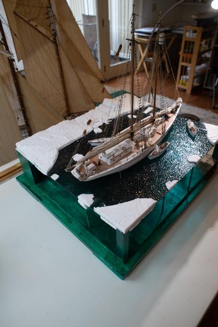
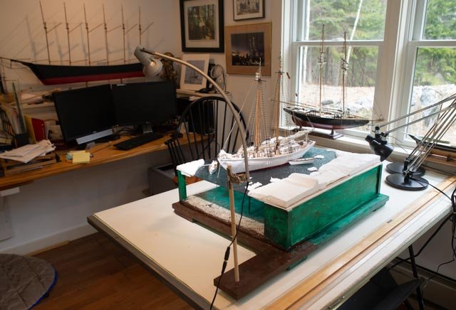
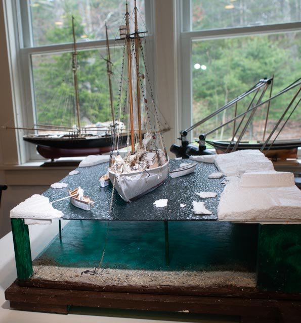
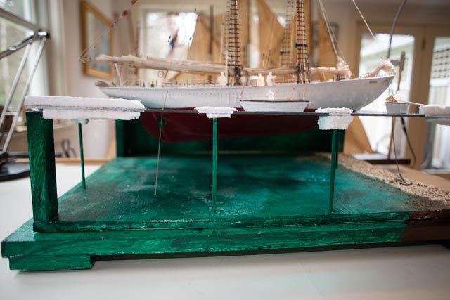
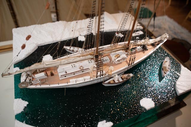
Post 36 get ready for final punch list before the showing Many of us need a little pressure before actually finishing a project. Since my last posting I have been working on 5 projects simultaneously. I got marching orders yesterday so two of the projects need to be ready for shipping to the museum store by next Friday. My third project is tiling the laundry and the rear admiral says we are done at the same time…oh!. The forth project is Charles Notman summer lecture which means I need to finish the model. I have most of ratlines done. Fifth is Aphrodite the first ship built in Boothbay is now an active log. For the museum I am doing Bowdoin and project two is repairing two old schooners. One is a large-scale Bluenose like my project from last year and a sister schooner the Herman Zwicker. I will have a posting on my Bluenose log to cover that work which has been fun. To the Bowdoin. We are getting there! b 284 I took the model out of the diorama so I could complete the stand and get it already to sit on a table. I then needed to figure out the scene detailing and work on the last few lines and things. b-285 turning around I found the safety line missing and I needed to tie off the 3rd dory. I also had to wet and coil some lines a bit better. I am still an amateur at that process, so I hope the crew’s grandchildren will forgive me. I first soak them with diluted white glue but they dry stiff. I find using a paint brush with water softens the glue and I can press and pull a bit. b-286 I noticed while reviewing these photos the white surround for the Bowdoin bow sign is too white. I need to address that….it never really ends does it?? b-287 Once a year we all should clear off our desk. I moved the diorama into this area as the light is much better. I am done to the real punch list now. Looking from this angle, the water is similar throughout. b-288 Here you see what I see. Beyond Bowdoin are the two models I am fixing up for the same dead line. b-289 Here again as we move aft, the water comes alive and the shadows extend aft on the deck. b-290 I find this interesting as the water under the stern is a beautiful green. I also like the strong shadows on deck. b-291 In this view the water is all the same. the light coming form behind picks up many highlights. This is opening my eyes to a whole new are of exhibiting models. Lighting can make a big difference. b-292 I love this view as it depicts exactly what I am trying to show. I n the July 1 1924 photo form the mountain top they had used ash to melt the ice around the hull. b293 Here you can see the completed diorama stand. the added layer below was painted out to match. The glass sits on lower ledge. The light stand remains outside the glass. b-296 Here we see a better view of the underwater beach and anchor b-297 Here is a fun bow on view. We see the bright light on the port side. Very different from the starboard side b298 For all submariners, this view shows the fun of supporting a model on 1/8th inch acrylic. We get to see the bottom. Note the stern anchor line that goes on down through the water. Please don't ask me to sut out for the dories. I suppose i should but not now please. next time!! B299 I leave this post with this overall view. We see 5 of the 6 crew. Perhaps I should add the 6th figure so nobody counts. I wish I could get some dogs and a sled All these views were taken with my 24 mm. I am fixing up a few oops and taking more pictures using the 90 mm/ macro. Then the final shots will be at the museum store in May. All for now jon
- 73 replies
-
- 11
-

-
Nick thank you for you r comments and support to the figures. I am putting together the final imaging and have posting to day of the updated diorama. I still plan to get up that way this season. My knee is almost back to normal so it should be soon. regards jon
-
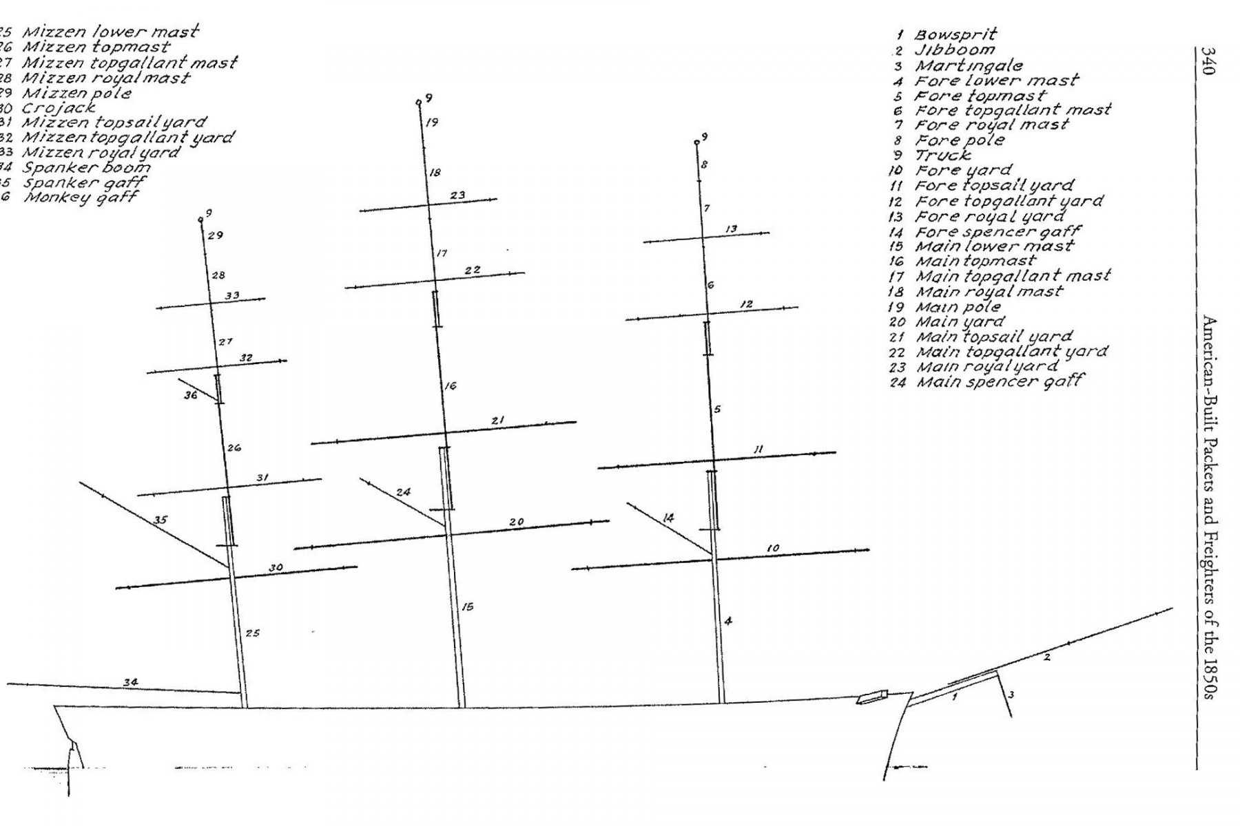
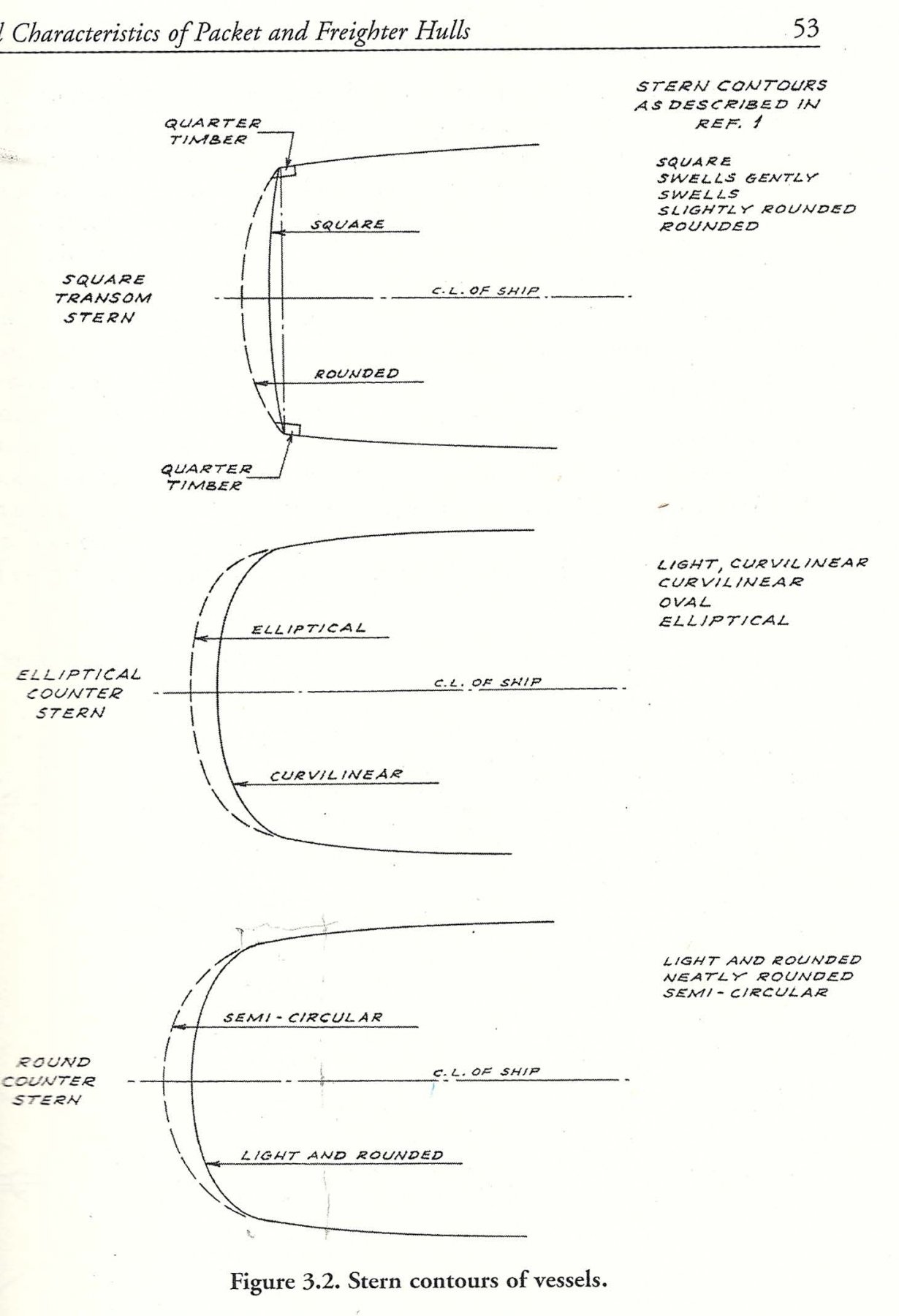
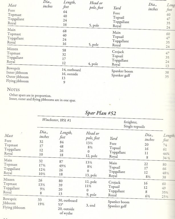
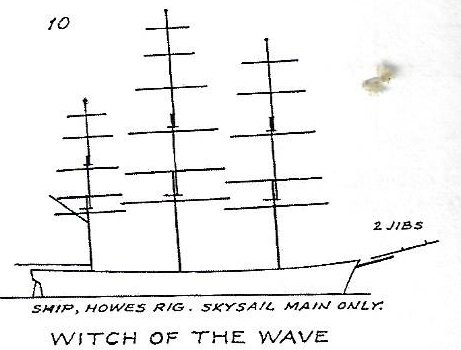
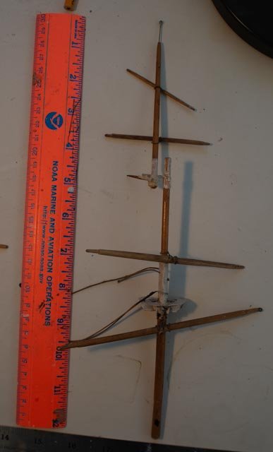
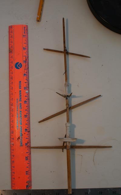
Post 8 First Study of masts and yards It was fun to read the chapter on the mast and yard design in Crothers book. It was this period of the 1850’s when the introduction of the split topsails [ renamed gallants at least in american trade I think] came to pass. Part of this study is to confirm if the existing model spars can be used. The short answer we shall get to is…. yes with some help sort of maybe.....sound familiar? Ap-50 this scan from the Crothers Book shows the basic consensus design of a an American merchant ship of the time. The chapter goes to explain the influence first of Captain Robert Bennett Forbes. The evolution of then top sails grew, due to their power, to be 60 feet wide and high. They drew well but in any wet weather became unmanageable. He was the first to split them in 1844. Part of his experiment was to “fid” the top mast "abaft" of the lower mast. He felt this approach improved the sailing function. Another fun fact is it was he who first popularized these topsails as Gallants in his pamphlets. In the 1850’s Forbes design was much debated. It was a ship builder/ captain named Frederic Howe who while building the clippership Climax in Medford, Ma., made two improvements. He realigned the huge top sail yard and fixed it to the cap of the lower mast. The sail was shorter. He then had a new upper top sail yard hung on the top mast and extended it clew past and behind of the lower yard , filling the previous gap in these two sails. Looking into more clipper ship plans I find this upper yard became known as the top gallant yard as per the Forbes pamphlets. This is all fun, but for our build we have to respect that Alma was not shown to have any of these newer rigs. Ap-52 this scan from Crothers book shows the understood rig of Alma that I shall use for the contemporary Maine built ship. ap-52 scan from Crothers book shows the Forbes Howe change on a clipper of the time That is all good stuff, but we need to move on to our build and check the existing model by measuring it against the designs of the time.. The measurements The first job was to take the scan above in ap51 and measure the components. I then measure the hull to get a scaling factor to bring them up to the model scale of 1:96. The second job was to measure the model components. One yard, the boom and gaff are missing, and one yard is clearly broken. The mast tops were all made and glued and I hope not to damage all of that. I will save that for possible use. { maybe} So, this post is for the planning of the reconditioning. I have a full excel sheet where I take the Crothers dimensions and’ scale them. Against each number I post the measurement for the existing spar. I won’t post all that here but the results as a list were amazingly good. Ap-053 Here we see the foremast . The lower mast is crocked with a splice and it is obvious looking at this photo, I have to disassemble the masts to install the standing rigging……. Ap-054 here is the Main mast. It is overall about ½ low. Lower mast needs to be increased in length by 1.25. [definitely replace]. Top gallant mast to be lowered about ¾ inch. Ap-055 Mizzen masts….very close over all variation about 1/8…clean and reusable…..maybe??? Ap-056 here I have disassembled the fore mast. ….if the 30 inch diameter mast was composite, does a simple dowel reflect how it was made. I must really think about this one. Ap-057 here I am making the missing yard. As to the measurements, the model yards were consistently a bit longer. The shoulder and tips were quite visible, so I may work to reduce that a bit There is more study to be had. One reason is I am reading in the Flying Cloud documents so I can best assist a friend on the model, I am finding 30-inch masts were composites with bands and all kinds of things. More of that in another post because I am quickly sliding down a rabbit hole. I just ordered Crothers Book on masting. $$ again. I am glad it is the journey. At least the book shelf will look good. Cheers jon
-
thanks Keith. I am finding I have much more to read and that is part of what I love in this work. I am trying to come to a set aside point because my other project all just got deadlines. any onward we go. I want to get the hull sort of done and masts figured out. jon
-
Post 7 Upper bulkhead shear planks and rails part 1 It is time to rectify the bulwarks and see that what we end up with is close enough to show the real thing. I started off by reading the chapters on the related items. In summary let’s look at two sketches Ap-40 This page, from Crothers’s book, shows the midsection of the hull. What I am after is the relationship on the side from waterline to monkey rail. By taking measurements from the drawing and scaling them slightly to fit the model, we find the issue I have mentioned of the deck being a little high. Not enough at say 1/16” to worry about. Ap 41 This view is the cropped bulwark for my planning. Here we see that above the pin rail there is an inner plank over the top of the stanchions [ bulwark clamp in nomenclature]. This made my use of a solid horizontal strip in this section show both dimensional separation of the pin rails and provide more solidity to the construction of the model. My next activity will be to build up the monkey rail. As per Crothers index of ships, we are trying to get to 4’-6”or 9/16” to copy information on Alna I will get to ½” due to the slightly high deck to focsle deck, so that is close enough for me especially as the dimension is a bit of conjecture. Ap-42 the shear plank is an extension of the main deck elevation and should thus be the ½ inch below the top of the top rail. In this photo we see the remnant of the old shear plank first too wide at 1/8” and too low. I have since carved it off and shall install a proper 1/16 strip at the right height. This also reinforces the previous decision to remove and replace the channels that were at the same level as this rail. Ap-43 Here we have an issue. This is the soaked future monkey rail stanchion that I set at the plank shear elevation to check out the problem of the too rounded stern. If I had cut out one inch fore and aft and ½ down, replaced it with a block and carved the stern, I could have earned a few more broom handles but ended up with a more proper termination of the shear plank. I will solve this one later Ap-44 here we see the first of three rings of styrene 30x30 to form the extreme curved water way. This is a short cut for this type model where everything is painted out. I would other wise have cut out the waterway from wider strips. I hope I am forgiven. Ap-45 I glue a little bit then bend a little more and work around the waterway. The first outer one is hard, and the inner ones are easier. At the same time, we have the wet future monkey rail stanchion bending to conform to the stern. Ap-46 here we are on the focsle deck. There is a sharp bend at the bow. We also have the monkey rail stanchion waiting for the stern to take shape. Ap-47 Here we continue by cutting to rough length, presoaking the bow section of the monkey rail stanchion, and bending them to conform. Ap-48 Just for fun, I have some progress on the deck houses, and it is fun to see how were coming along. Ap 49 Here we are gluing the first aft section of the monkey rail stanchion. I am using scrap shims to hold it to the center of the main rail, the bow or stern water way. We are away for a while and spring is coming, I just want to get the bulwarks and main houses done before the slow down for summer. I am still working on the other projects with summer dead lines. this model is for next summer Cheers Jon
-
Keith It is such a joy to sit down with a cup of coffee and read the next few pages of your build. I just learned all about options to finish wood at this scale , to turn portholes and to punch acrylic so they look real. This last image showing the hull should make the team rooting for paint pause.....if only briefly. It is gorgeous. I can't wait to find out what you decide to do. Jon
-
Mark Thankyou for the tip. I typed in U S Constitution in dry dock and got dozens of photos. They show several variations. What is interesting is they are the opposite of my results. The inside curve near the stern had large areas where the copper color stayed. Perhaps movement of water. On the other hand, the U S Constitution does not move very much so what that might mean is out there. The process of seeing them makes me feel better. To the real modeler I may have strayed into folk-art, but I am ok with that. Cheers Jon
-
Kieth there are two types ...one is two part and very hard etc and the second that I love, is one part and forgiving. It is called Glazing Putty Bondo...Glazing & spot putty it is red cheers
-
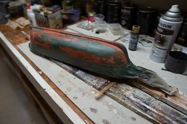
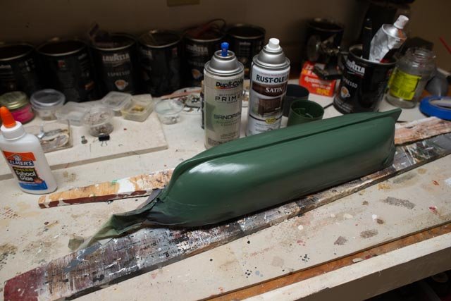
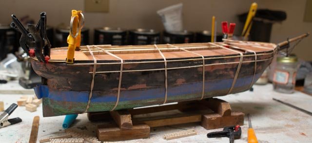
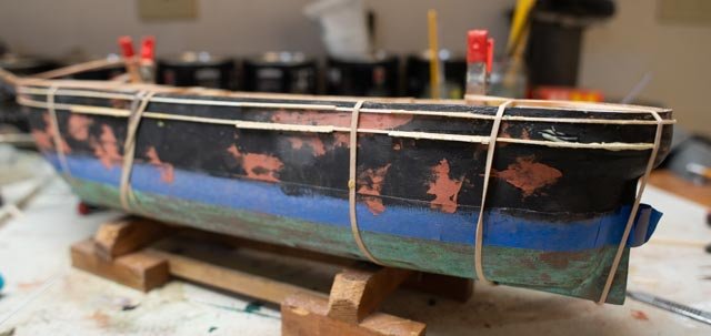
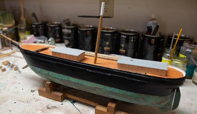
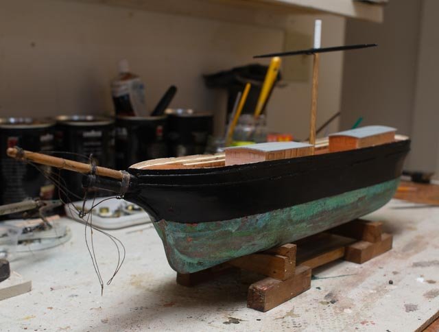
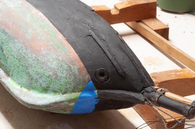
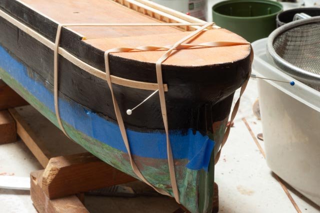
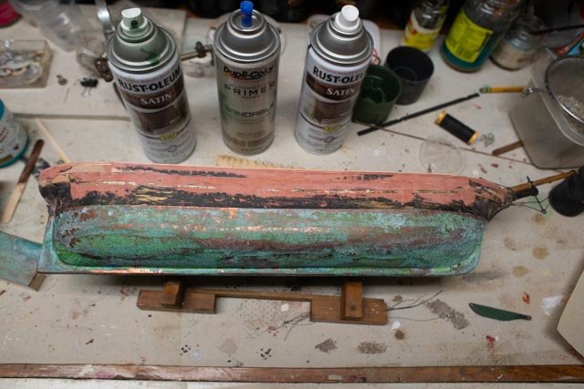
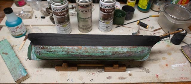
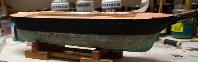
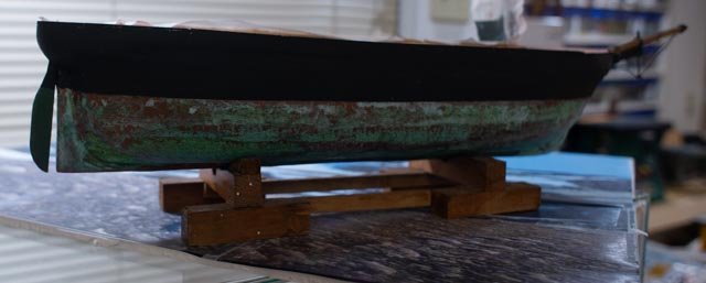
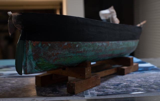
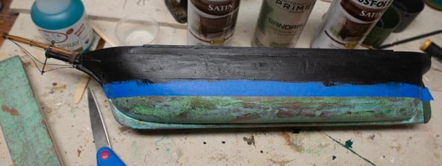
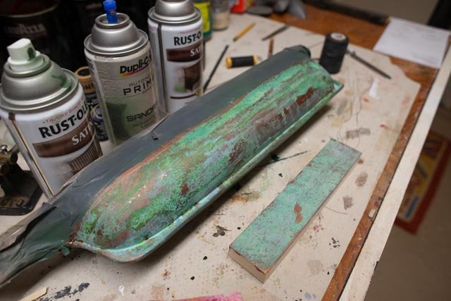
Post 6 Copper Hull experiment…the patina part 2 I think I ‘m going to proceed. I can always come back and change. Here is my rationalization. Ap-33 I turned her around and tried the other side. This image shows we are on side two with coat two ready for treatment. Ap-34 here we have the same issue as the other side. I only did two coats so three coats as an issue is eliminated. I was very careful on application, and the bare spots still came up. They are consistent on the roundest part. Before removing the masking tape, I did a second application. There is improvement but some green is getting too green. Ap-35 another issue is which black to use. I started with this coat as an experiment. It needs another cycle of filler sanding and another coat anyway. This trial is the ink black that is so perfect for flat iron work. It is flat, I mean really flat. The debate is ..was paint in 1853 ink black or oil and other pigment. Should one use flat or satin. I just don’t know the evolution of paint. If tar it is a bit shinny and I like to use ebony stain for that of ratline slats and things. All the books say is black. I will do each side different and then decide. As to the look …….I mean when the model will be displayed how does this patina and paint look… Ap36…This image fairly shows it will be low and not under bright light on the lower hull. As to the message…. I am trying to depict what things were, how they worked and focus more on that. I am not the fine workmen to focus on the beauty of the wood or the skill in finish and carving and the like. Ap37 a glance of the hull at eye level as one walks by… I want one to look at the model and sure like what they see, but also understand from the glance what things are made of. That bottom says I AM MADE OF COPPER AND I TURNED MOSTLY GREEN. The green paint did not. Ap 38… I have read the copper plates under water did not change to all the same green. The copper near the water line that saw air was the greenest, some boats saw more time in dry dock, Some areas where fast water kept the copper hue longer[ maybe??]. All these things are perceptions. And we have no copper in our lifetime to look at. Ap-39 I went ahead and painted the opposite side with the satin finish black. In the write ups on 1850 paint, Crothers discusses the mix of ink black with red lead and “paint Oil” [ other reference said linseed oil]. If they were painting yards black, they added turpentine to the brew as it... "gave a gloss". [ Therefore, without adding turpentine it may have been flat. I have a different issue. This hull is caved spruce. Despite three treatments of putty and sanding the satin finish highlights every little defect and takes the eye the wrong way as to scale. The spruce grain that I have filled and sanded three times is still there and ruins the concept that one inch of model is eight feet in life. On the flat iron side, there are defects that I can eliminate with another round of fill sand and paint to the result of the back ground is non discernible. That is the look I need for this repair. Once I replace the plank sheer and the channels, I want them to be what is seen not the grain that despite my effort lives on. Conclusion…that is better said my conclusion What I have may be out of scale and to some will be awful. Perhaps I should do copper plate and then acid etc. This test shows my attempt to clearly explain the bottom is copper patina. I spent only $40 on material and having used just 10% of it means that supply could do many more models. I feel it is better to use on the larger hulls meant for RC sailing and someday I shall treat my large 1853 Pilot schooner, I showed in the last posting, that is currently just green paint. I have a friend building a 6-foot Flying Cloud and maybe he will like it. I believe the results are better than green spray paint. ..The option to install thin Copper plates to this hull would have been easily $100++. The market plates are meant, I believe, for larger scale 3/16" and up, so I am not sure what to do. Then I still would have the issue of how to treat to get patina. As to scale with the tape option…..would one punch the nail holes at 1:96? I think not……and unpunched tape just is not worth the effort to prepare the hull. Regardless there is always so much to learn. Years from now, I may laugh at this conclusion. This model is not a fine piece to have any great value. It is chance to salvage an old model and end up with a decent replication of a ship built at the time, so people can see what was built in our harbor. With that logic or at least opinion, it is time for me to move forward. I will do more touch up on the Dixie Bell copper, as handling will cause some damage and I need to address the “too green” spots. I also need to do the rudder. I tried sanding with 400 grit, and it improved the look by removing the roughness and blending colors some. That helped reduce the scale issue. I will use the Ink Black super flat paint for the hull and then a satin when I get to the painted yards. I will re address this when we are really done with the hull. on to the bulk head Cheers
-
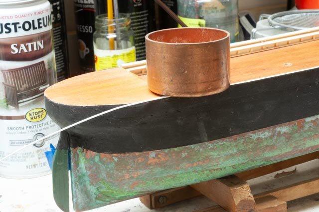
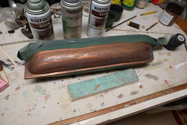
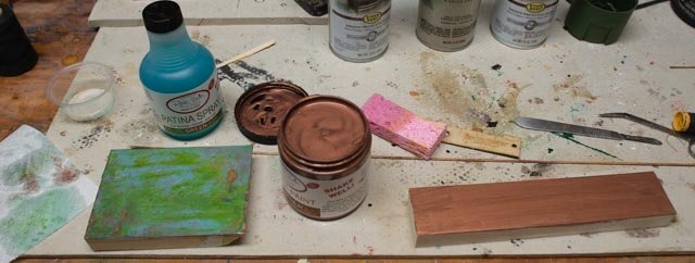
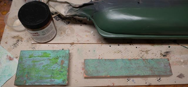
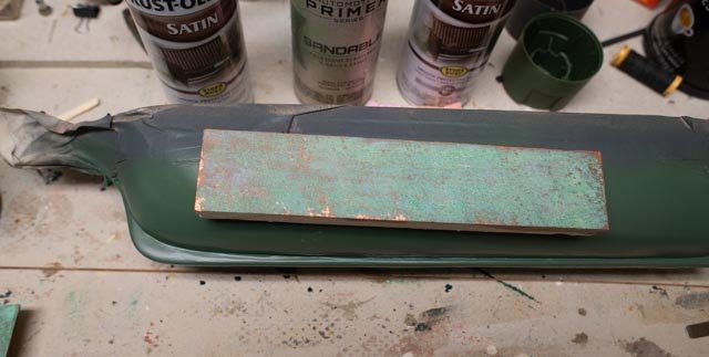
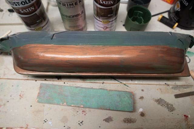
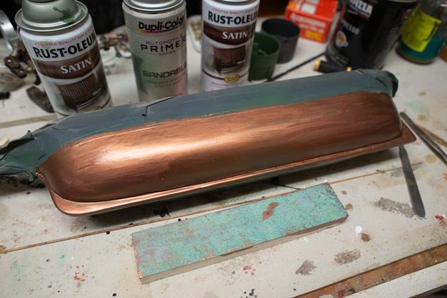
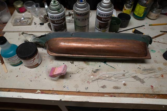
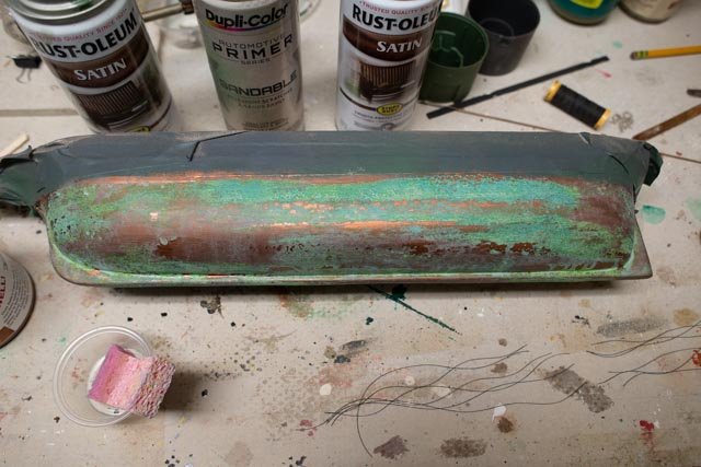
Posting 5 Copper hull experiment I always like to try something new. It does not always work. I am setting myself up for big oops, so let’s follow the bouncing ball, as I attempt a craft approach to copper patina paint. Ap-25 the secret supplies arrive. On the net I found many choices but was most intrigued with the Dixie Bell paint procedures. Here I have chosen the copper patina paint [ in the jar] and the green [ vs optional blue] patina spray. They show applications to vary from the spray to sponge. The sample on the left I did not like. It was too much liquid which over treated the paint and retained a chartreuse green. On the right we have the second sample. One paints a copper layer and lets it dry. One then applys a second coat and added the liquid to the wet paint so like blackening agent for copper and brass fittings, the metal particles suspended in the still wet paint can turn color. Ap-26 here the second sample looks ok Ap-27 the test. Setting the second sample over the green hull I decide to go for it. Ap-28 first coat per instructions….let it dry Ap 29 I was not satisfied with the cover of one coat over the green so I added a second coat….maybe oops. Ap-30 Here as the third wet coat gets sponged, I am optimistic! Ap 31 hours later I am perplexed. Why so different than the flat surface. This may be great results for life size plaster bust that I want to look like old brass but for the scale it may be wrong. Ap-32 here if you compare closely I have put dabs on where the copper showed the most and added more treatment. It’s better but the green if hit twice seems to get too green. What to do. Stand by I am trying side two Jon
-
Thank you Keith Now I am ready for some real comments on my next two posts.
-
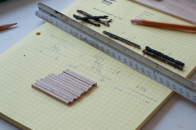
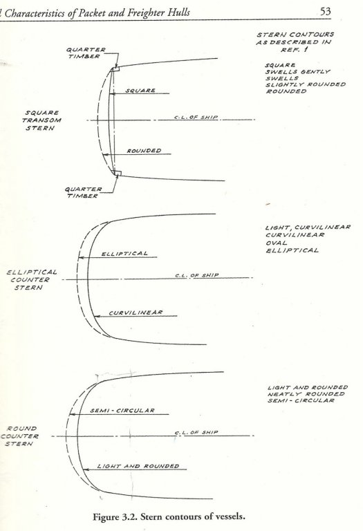
Post 4 Hull part 2 Ok it is time to move under water line. This carved hull of spruce had large grain, two knots etc. That is fine if I strip it and varnish it as a novelty. I am trying however to depict what a ship was like that was indeed build here, and not what the model is made o. Therefore a crisper cleaner look is needed in this area. The process is routine, the issue becomes do we do three times through or keep going. How are we going to depict the copper? Ap-018 this view is after the first full cycle of bondo, sand 220 grit, putty, sand prime and sand 400. Ap-019 second time we delete bondo and go with smoother glazing putty. Then gray auto filler primer. Sand that 400 grit and spray the green finish. Now we add more glazing putty and sand…yes a mess but we all know it well. Ap-020 the transom. Here is the discussion on different transoms at the time. Alna was the bottom one, Lightly rounded as per this scan from Crothers book. Well our model is defiantly a semi-circle. Looking back to the photo ap-015 we see that if I cut the transom to the right shape shown as pencil on masking tape, I would uncover the rudder. The other alternative would be to cut out a block and set a larger one in its place. Then I would need to carve the transom to extend cheeks and create the correct “lightly curved” profile. I decided to leave as it is and simply record the finding. Ap-021 in this photo one sees the first sailing schooner I built. It is large scale and meant more to sail than to replicate any details. I used rattle can soft green paint to replicate the copper bottom. This is my starting point Ap-022 well here we are as we stand if this level is good enough. This is the third green paint cycle of paint and patch and repaint. As a sign, the can ran dry, so perhaps it’s a signal that we reached enough. Stand by because I am going to try an experiment before leaving the process as is [ loose interpretation of patina] material is on its way. In between coats and other jobs I found a need to rebuilt the standing rigging channels. Ap-023 Here I use the mini saw to try to make them the same length. I found some scrap hard wood similar in color to maple. I find bass wood to"frayey" if there is such a word for this type work. I have a big block of pear someone gave me to mill down but that is a winter project in itself. Ap-024 here I sliced out the groves, again to make them look a like. After this step, they were filed with triangle to get to a groove. I chose to make the lengths and slices based on the Crothers plan which was a little different that the old model. i will be doing the standing rigging on this plan so the groove count will match up. Cheers Jon