Jond
-
Posts
876 -
Joined
-
Last visited
Content Type
Profiles
Forums
Gallery
Events
Everything posted by Jond
-
 Ron good to see a neighbor on line. Thanks for pointing out my spelling. it has never been a strength but as you see it does not slow me down. there was another silly mistake in that post....I called the maple strips I was color checking before adding in making up the "pads" planking. that too was not only wrong but mis leading as the planking was shellac. happy to have you checking up on me cheers
 -
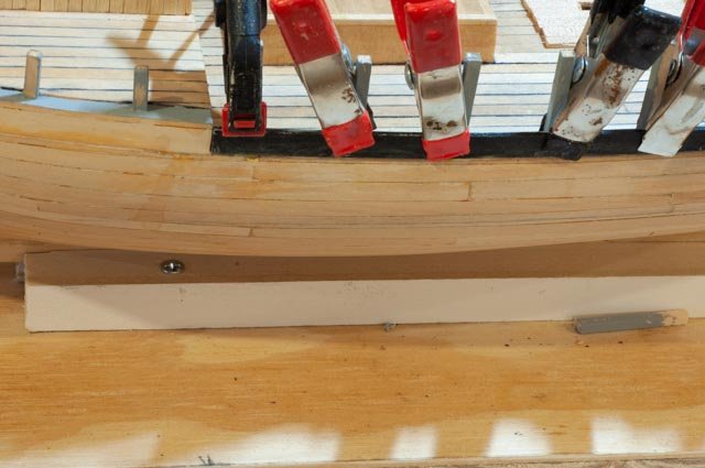
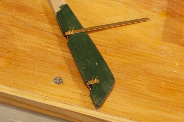
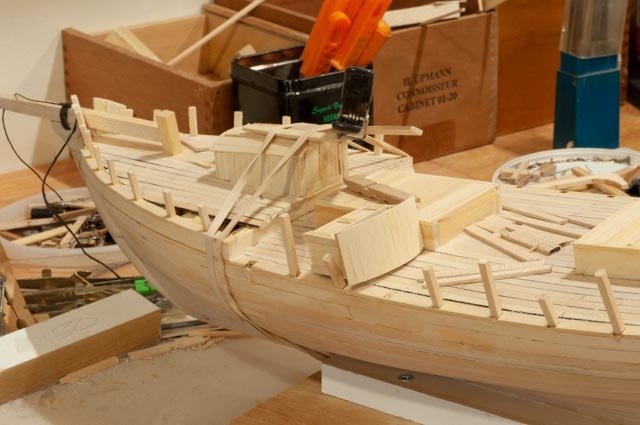
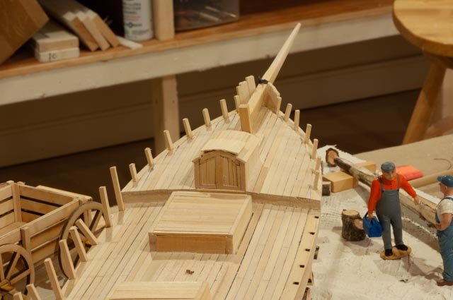
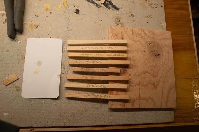
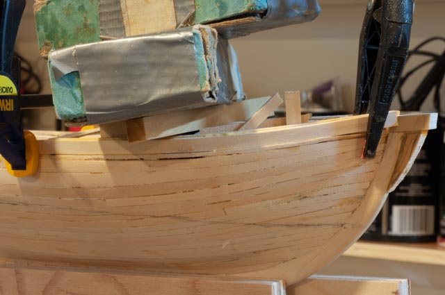
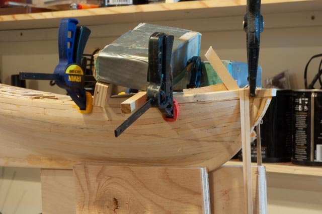
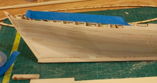
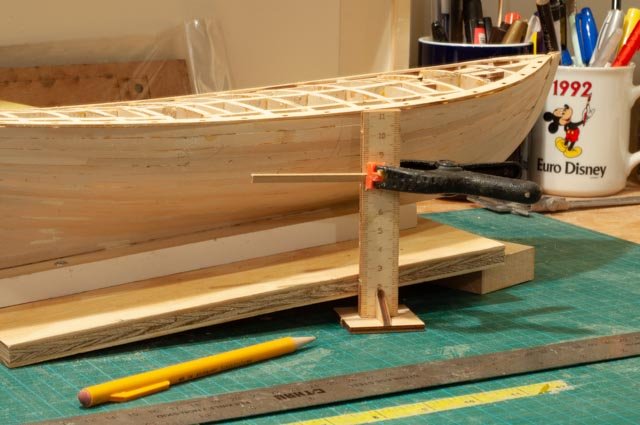
Post 21 Building bulwarks To move upward into bulwarks usually means colors should be all decided. I think this is better because I like to pre-paint parts at this point to give sharper edges and things. We shall have one of three strakes white and the other two black and three different thickness also make this easier. I hope at least 165 here we are with two coats of shellac and some steel wool rubbing and vacuum to clean up. No more stalling, I have chose to copy much of the color scheme from the Essex display. My thoughts are that carbon black going into linseed oil was easy and a cheaper alternative to how ever they made green. I will still do green above the waterline but assume the less expensive paint would be there before copper, below water. For the inside rail’s bulwark, waterways etc. I will use the gray as shown on Essex. Again, a simple mixing to achieve and not more imported pigments for this schooner built in a remote site. I am guessing of course 166 here I looked at four color samples for the pads… wipe on poly, plane, shellac and cherry stain [for some reason is upside down in this photo]. No worries it was awful and I am going with the top one, wipe on poly. To build the bulwark, I will also follow much of Essex. There are three strakes involved. The main deck will get a 1/16 to better have scuppers square cut/ filed. The second strake is 1/32 white out and gray in. this detail hopefully will give a sharp edge between colors. For the top strake, I will use the kit supplied 3/64 strake. Again, it will create a crisper edge of black over white on the outside. I assume I will be trimming this as it is a good 1/16+ too wide. I will dry fit and decide when to sand. 167 here I have dry fit things to be sure I am on the right track 168 here on the painting bench I have the three colors involved. Black outside and gray inside for top and bottom. The big kit pieces started to warp with paint, so I place lead and plate over them as they dried. They will need to be scored too as they are the size of two planks for convenience. The little stanchions are waiting their turn to become gray. 169 here we go with the first one. I am a little nervous as the aft build out of the tombstone will need to be fit in. I think this will be easier than making a frame and trying to get the planks to meet up. We’ll see later if I am right 170 inspecting the fit after gluing and clamping, I found the strake came up a bit creating a gap. I must fix it! 171 Turning her around and elevating the whole stand to clamp both sides down might work. 172 the gap went away, a little glue came out, but we should be ok 173 just a detail as we make up the rudder fittings. I increased the size of the band just to satisfy me. 174 here you can see the other side with the pins in place. Now I need to dig through more boxes and see if I can rescue my blackening kit. I found one little piece of solder and it may be enough to finish. All for now
- 69 replies
-
- 5
-

-
- diorama
- Glad Tidings
- (and 2 more)
-
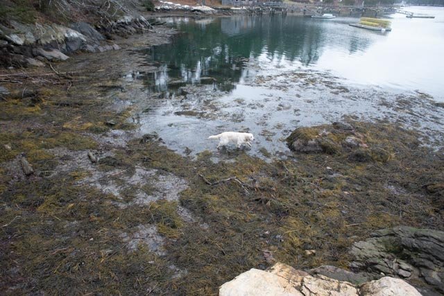
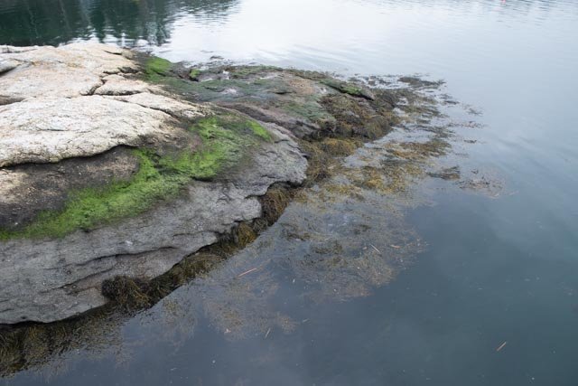
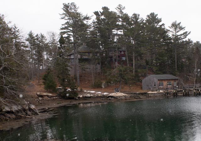
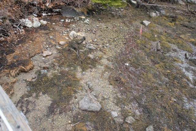
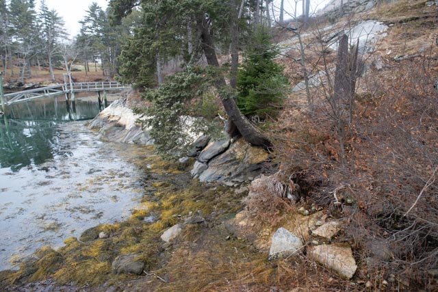
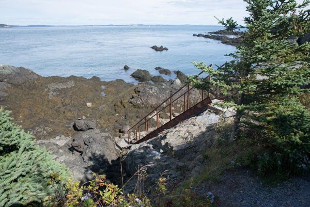
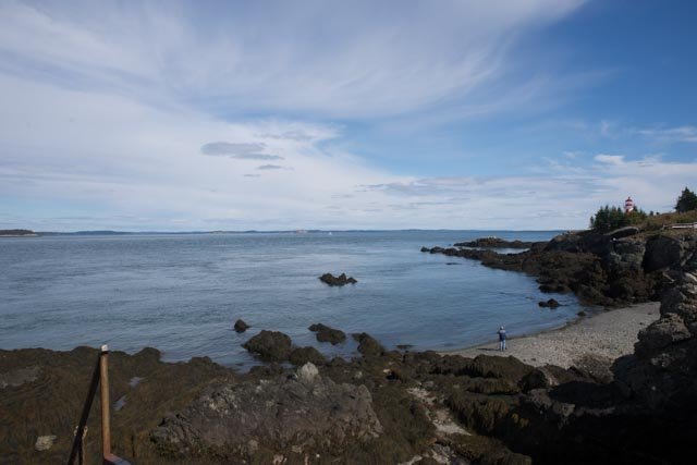
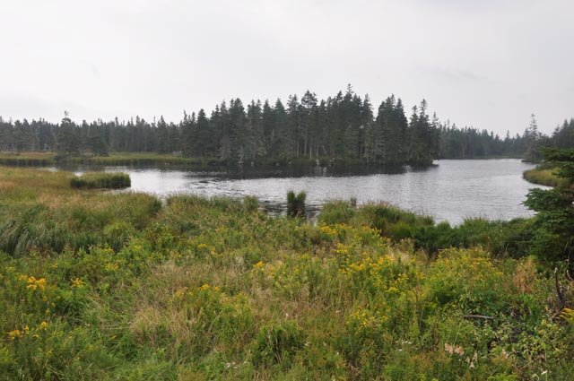
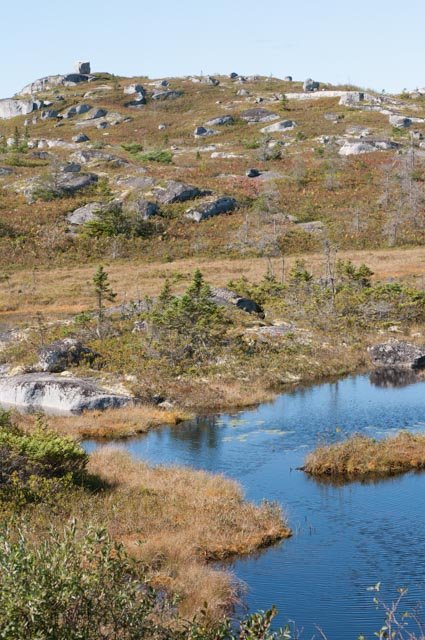
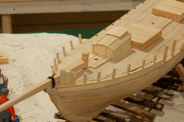
Post 20 So what is this seaweed all about?.....or where is it? We just had a January thaw, so it is time to reflect on what the diorama will look like. The following study are first of details of rock, dirt and seaweed taken from my dock area which is within two miles, as the crow flies, from where this schooner was built on the Sheepscot river. 156 here our shop dog is helping study the color and texture at the waters edge. This is done at the same time as the diorama, about 3 feet below the highest tides and two feet below normal high tide. 157 see the bright green in the top one-foot zone then the granite is covered with barnacles and growth making it gray. Then in the wet zone, seaweed is brown with yellowing tubes that are full of seawater. 158 Here looking about 100 yards away one can see the town landing. It shows the angle of slope typically chosen for this type work. That actual ramp is hidden just past the white granite ledge. 159 here looking down above the water we see the gravel/sand that is a good solid base for the slip way 160 here along the edge of ledges one sees trees are right there at the water’s edge. The brown grass in the foreground would have been eel grass just 20 years ago, but those little green crabs that came here as part of warming , burrow in the mud over winter eating all the roots to the demise of the former shore land grass lands. Now let’s look at what it might have been years ago. For that I combine a few shots from both Nova Scotia and Newfoundland. Wonderful places for anyone to visit 161 Here at the end of Campobello Island one sees darker rocks that get more submersion thus more growth and seaweed. Walking down there, one finds the gravel is larger sized, not so sandy as ours. 162 Here we see to the east that gravel area developed into a rocky beach. We have them here too. One might think the beach to be more conducive to a boat works but evidence shows other wise 163 here driving the cost of Newfoundland we see what I suspect the east side of Sheepscot river, where our schooner was built, might have looked like. The eel grass along the banks holding soil. Here in the foreground after years of soil migration, more permanent dry land and wildflowers take over. Once we lose the ell grass the water invades and removed more of our shoreline. 164 here we are near Peggy Cove Nova Scotia. if we think about all of the timber that was taken from land adjacent to the Maine rivers, much of the coast line looks like this area. this area is not forested but a glacial moraine leading into the sea. Anyway as we see the coast today and need to remember the treeless landscape of the mid 19th century we have many options. Fortunately for me the diorama only includes a tiny area right on the water's edge. If I can not figure out seaweed, the edge might look more like this one. then some smart viewers will likely ask....where is the seaweed? So now with all those visuals in mind, I need to take everything off the diorama and finalize the shape of the plaster and start painting. I still have no idea what may work to show seaweed. I may bring in some granite pieces, but the scale may not look right. Cheers
- 69 replies
-
- 6
-
-
- diorama
- Glad Tidings
- (and 2 more)
-
Thank You Eric. the research and learning and visiting related sites makes these projects a joy. My Library grows too. jon
-
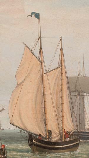
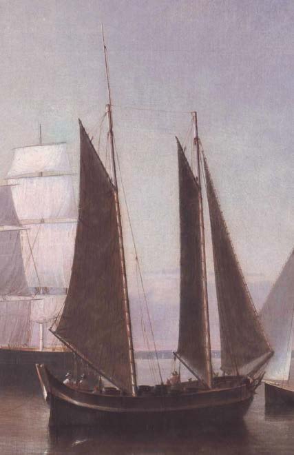
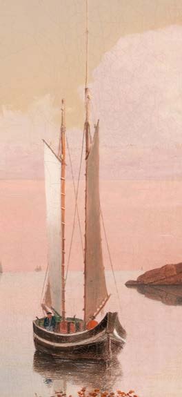
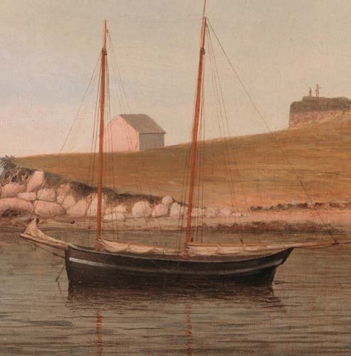
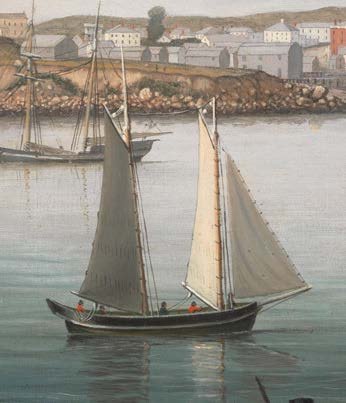
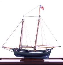
Post 19 My search goes on for paint. both these models above, and the 5 cropped paintings I include below show lots of green in the Gloucester fleet. Reading what I can find about early paint a find a few things of issue regarding availability of green. I just read that paint was heavy [ I guess it still is], and therefore was not centrally manufactured and shipped. it tended to be more local. perhaps in this case Bath about ten miles by water away. reading about the green pigments of the time I learned they were very toxic. The sequences of inventions of green was tedious. Scheele's green late 18th century was full of Copper arsinate which reportedly killed many. it was followed by Paris Green and then emerald green. the pigments later were used for poison. So was that readily available in Bath Maine in 1816. since those green pigments shades were , at least looking on line today, brighter or even yellow green, they did not look like the common dark green of new England we know so well. maybe since yellow and blue were such common colors the locals mixed them, and got the green we see. it would be good to learn about that before the final commitment. a simpler answer is to leave off some paint or use all black. I think the models will look better with the dark painted hull contrasting with an unpainted deck and finishing. here are a few online cropped painting that show a consistency of look. Perhaps this is not too complicated and if the two models chose almost the same color scheme i should stop worrying and just move on 148 this image was cropped from about 1860 painting....see the green below 149 not sure of date...different artist but again...green 150 here i crop it and can see the copper bottom 151 mid 1850 and again black above and gray of green in the shadow below 152 here we see some of the deck color and again green around the inside of the bulkhead 153 this cropped image looks all black 154 same again inside and out 155 here is the working study. I printed out the images and taped them to use as reference as i build up the bulkhead to reflect the right design. The more I study the Essex image above , the more similar details I can see on the drawings....scuppers by example. I did put on some shellac today, so we will see how that went tomorrow. and perhaps we paint the combing of the hatches. they would have been installed before the decking. I scratched in and darkened some deck plank butt joints and now have to think about adding nails all across. it would be much easier to do before the bulkheads. But i find can be a distraction. cheers

- 69 replies
-
- 5
-
-
- diorama
- Glad Tidings
- (and 2 more)
-
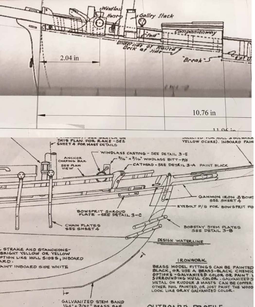
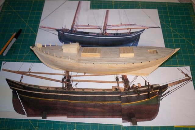
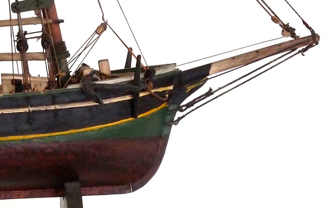
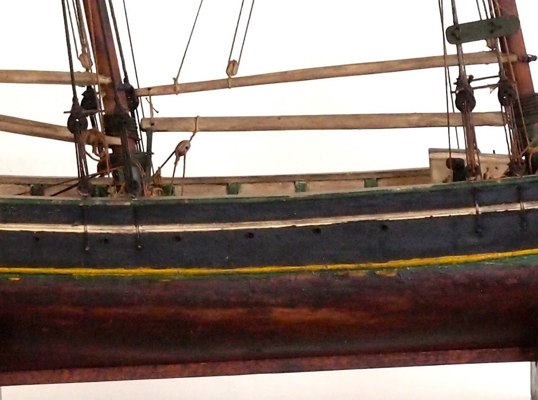
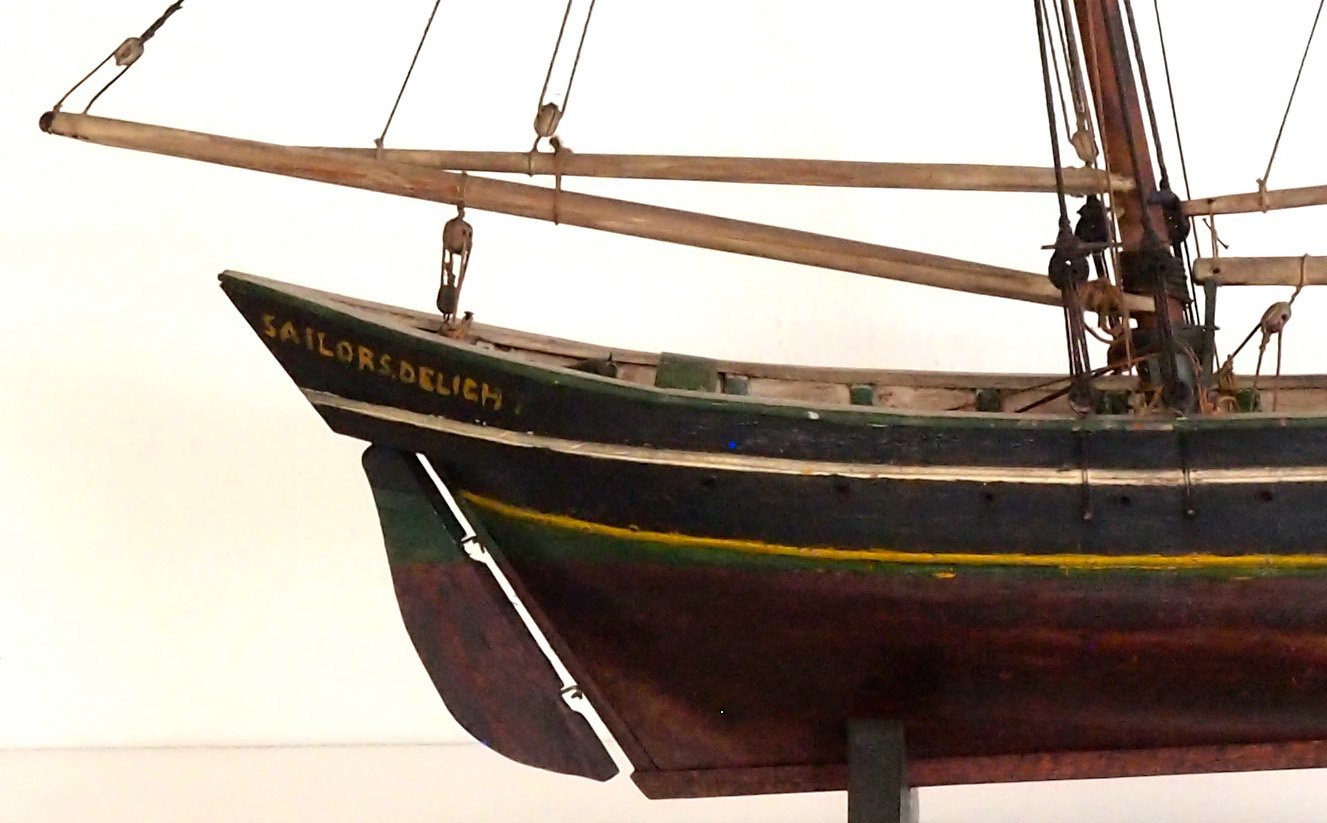
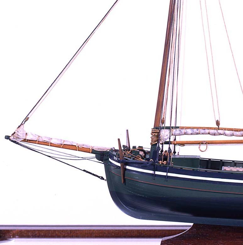
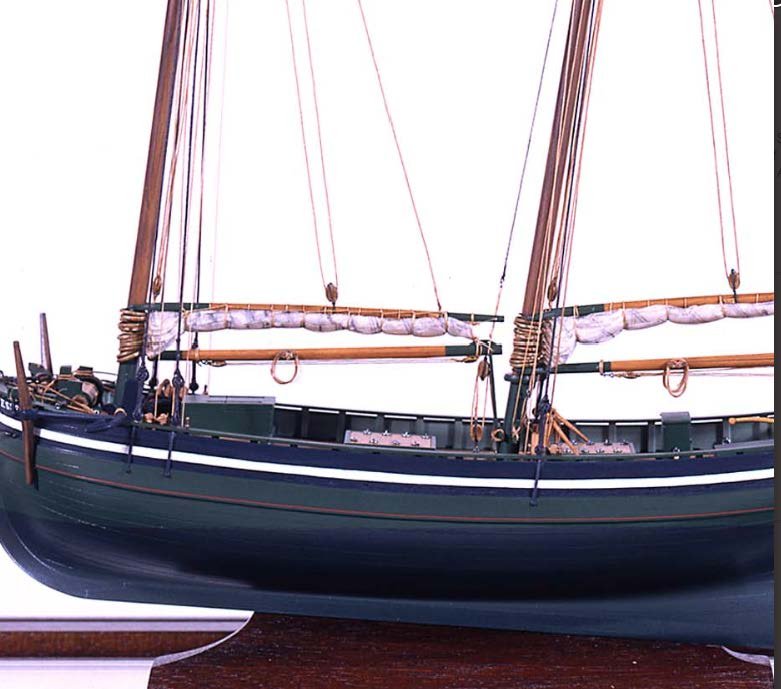
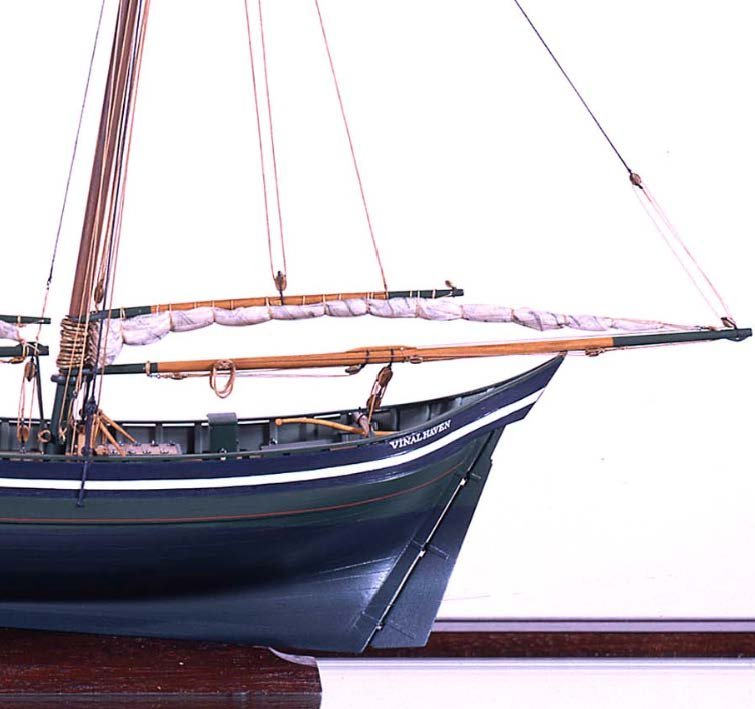
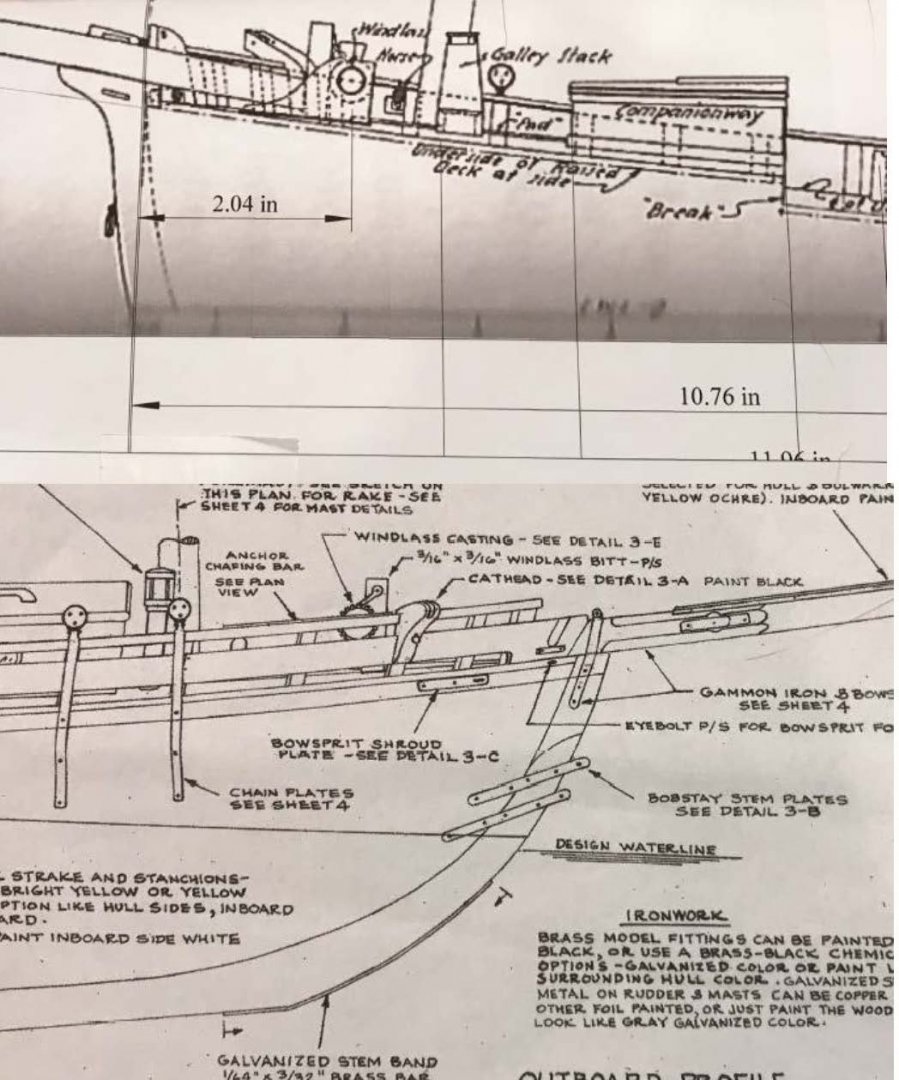
Posting 18 Picking the color scheme The first model to study I showed a picture of a model in the first post. [ item 2] For the record this image is sailing left to right. [ starboard side] To give credits I have since learned it is the model of the Pinky Sailors Delight by J Doane Nickerson and is part of the Cape Ann Museum. The model maker was apparently a sail maker by trade. It part of the ….Fitz Henry Lane Online which copied from their site is……… is a freely accessible interactive and interdisciplinary online resource created by the Cape Ann Museum. The website is organized around a catalog of the paintings, drawings, and lithographs of nineteenth-century American painter Fitz Henry Lane (1804–1865). Their comment for this model is………………….the model is wood, metal, cordage 20" l. x 19" h. x 3 3/4" w. [not to scale] it came to the Cape Ann Museum as a Gift of Mr. J. Hollis Griffin, 1940 (891) "Pinkys" were early nineteenth-century schooner-rigged derivations of Chebacco boats. This model is a good example of a traditional “sailor’s model,” or in this case, a sailmaker’s model, Mr. Nickerson having been a sailmaker. Here are three images that I created as I could blow up online part of the photo image and captured them. 141 the bow view: here I am focusing on the bow sprit construction, and the combination of painting and bands. The waterline down is copper. The gold line follows a strake in the upper band, three planks below the main shear strake. The white line follows the shear plank of the raised foredeck. There is a splash guard above the rail like future schooners. The anchor goes through a hole and not a diagonal slot like the newer GladTidings design. 142 the middle section: Here we see the scuppers and the relationship of the painted inner bulwarks. They are solid and built up and it there one can calculate where the gold and white bands are. There is no obvious protrusion [ molding or cove] just the color. The copper looks like the painted approach I am using on my other build Aphrodite, the first ship built in Boothbay. That model though is 1:98. We have just the opposite problem here at 1:24 if we choose to show copper. As of now I want to show it. 143 the stern view: here I see the build up of the high stern as being less dramatic. I think it has no tombstone. The binnacle shows just over the rail about 25% of the height. What is significant is how overpowering the mast and rigging are to these views. Everything I am forecasting would exclude those elements, so the deck is perhaps quite bare. What that also means is my cute little ¼” square holes for the mast step is based on model instructions and I need to reconsider that sizing. Typically, a mast passed right through the deck, so the hole needs to be round and full size…. perhaps another oops A second Model to study 144 was a more recent find. It is listed in the same site as above …the Model of the pinky "Essex" Model and photography by Erik A.R. Ronnberg, Jr. wow we all know who Erik is. That makes this model, and close study verifies it, a masterpiece. Here are the same three mages that I used the online tool to blow up the image and then captured for my further study 145 the bow section: Here it is 1821 and the bow sprit looks more technical. It also looks different from the drawing that came in the study of Howard Chapelle’s book with the same name Essex. He talked about some confusion and how the models and some of the half models did not line up name wise. I don’t want to get into that. I am following the drawing not the subtle difference. More important is the coloring. It seems to support the dark green and black. Both colors easy to make and so prevalent here in new England in the early days of lamp black and linseed oil.. Everything for shutters to cottages to boat after boat had some form of green. I think I am going to be safe with that choice. the gold is clearly a molded element, much easier to build 146 mid-section: here we see the hatch covers. that gives me a hint for the whole deck the hatch light coloring, with coming that looks to be painted, and I am guessing it is the same gray of the inner bulkhead. There seems to alternate dark green and gray. I like it because it is easy to do and with this builders name, the idea has definite Credence. Here the masts do not look so ominous. I am grateful. I may do some measuring and go with this and the size on the drawings. I also feel better seeing two shrouds and not the single shroud on the plans. I will at least build the chain plates and lower dead eyes 147 The stern: look at that binnacle. I think I am ok with my curved roof . here unlike the example above the raised stern is more technical. It overhangs out and beyond the rudder coming toward which must be a tombstone or at least an triangle. More study before I build this thing. i know in the spring i need to take a trip down to that museum and see what i can see and learn. So a lot to think about All for now…still reading
- 69 replies
-
- 6
-
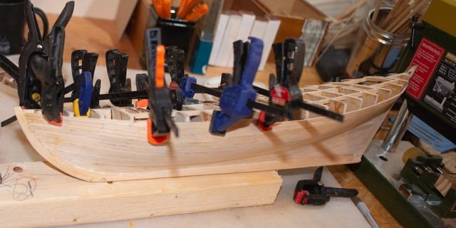
-
- diorama
- Glad Tidings
- (and 2 more)
-
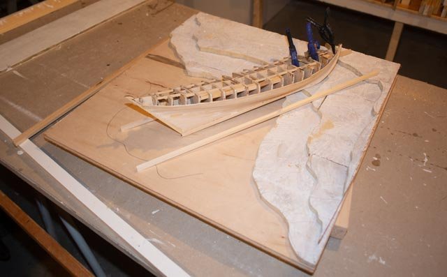
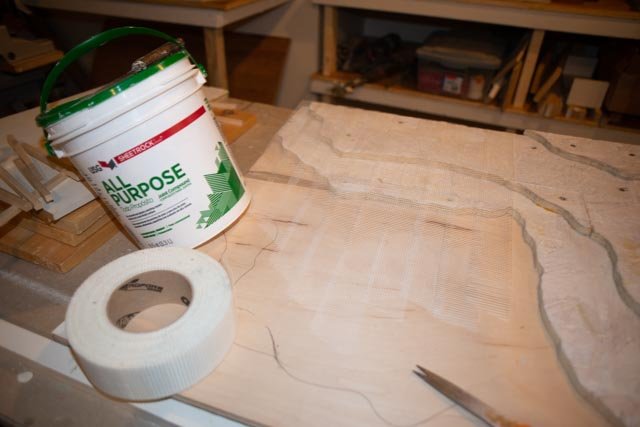
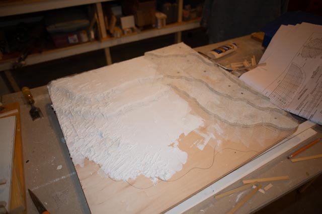
Eric thanks we are always learning something. next for me is to see what it does with or with out stain cheers
- 69 replies
-
- 1
-
-
- diorama
- Glad Tidings
- (and 2 more)
-
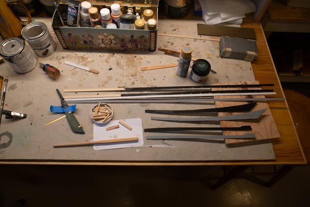
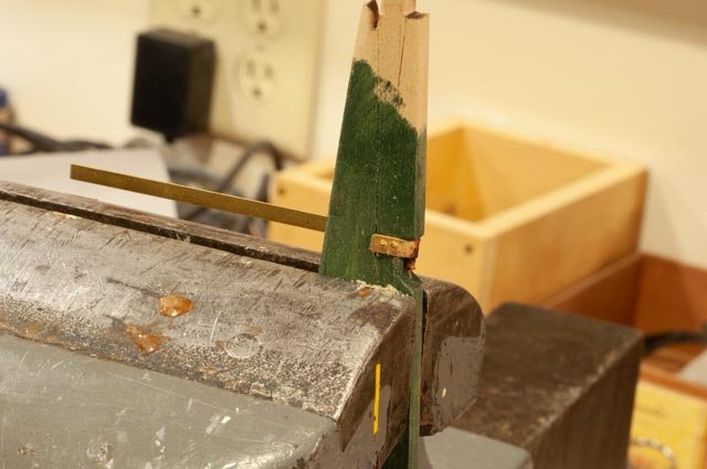
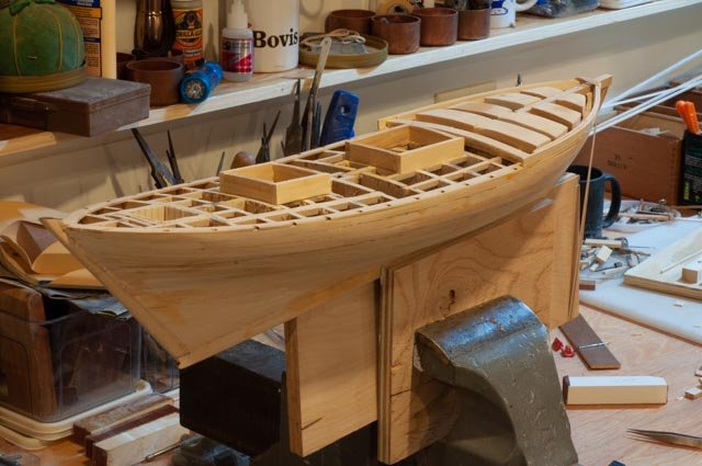
Post 17 Almost done with the deck This posting is to include the rationalizing I am doing for the next few steps. It is cold and damp outside, so a good time to think and maybe decide. the 5 next steps 1. How will I finish the deck, since that must be done before building up the bulkheads? 2. How to build the bulkheads…..in 1820 ish they did not look like Glad Tidings; there were normal sided with scuppers 3. How to treat the outside of the hull. We need to get a legitimate look, but also what do we want to show under s=construction 4. What do we do for spars? 5. Can we decide on the slipway and get it built into the diorama? First of all, let’s catch up on completing the deck. 131 here we have rebuilt the companion way door to the right height, and I am gluing a piece of 1/64 birch play onto two rails to receive planks making up the hatch cover. The roof on the binnacle laying near by is complete using the same method 132 here we have completed building and have started the final stages of sanding the deck and furnishings . 133 here we look aft. The stanchions are loose fitted and the horse cross knee is ready for the aft bulkhead work 134 our stern view looking into the binnacle 135 and to the new door and hatch cover at the forward gangway Now a progress review as we contemplate the next five operations listed above 136 bow detail here we might be beginning to rig the bowsprit and forestays. I am still looking into Fitz Henry Lane web site for painting schemes of the period. the pencil waterline down will be copper over green. the top three strakes of the hull [ below main deck] plus raised side of foredack will be black as will the solid bulkheads. there will be a gold pinstripe separating green from black, and a white stripe along the fore deck shear plank going all the way aft. The top rail will be green if painted and insides of the bulkheads ivory /off white gray. the uncertainty also leads to fresh wood if it looks good. 137 bow top. Here the deck finish is most important. It needs to look very new. I am thinking little if any paint. On the other furnishings although the hatches may have been painted …we can wait for those thoughts 138 stern overall. This view is all about the story…building the first schooner on a primitive site…..it’s the seaweed and understanding of the tide needed to launch and the hand made slipway. Ugh I have no idea what I am going to do about that seaweed. I think first up is to complete the slipway and plaster work to make all of that at least stable. then add some real rock as and background dirt paint. 139 stern detail….here we may want to think about a few pieces of copper going on over paint. Very hard and worrisome to consider at this large scale. I have again no idea where to begin…the raw pieces would ¾ by 2 inches. I also need to build up the rudder. Next Steps 1-5 preparations 140 here I have taken the kit provided milled basswood for the slipway and made up samples of different finishes. This is a long term test because the issue is not just what the look is today but how about after a year. Example: linseed oil turns black in the sun. what do the other items do. I have spent a few hours and will do some more reading in the finishing hints are to get help deciding. i do not have time to wait. I know normal varnish darkens with age. it's great for masts or wanting an old deck. This diorama however, is a snap shop and it has to stay looking new. Now, I like the shellac approach [ third from the bottom] and its immediate affect…a slight darkening to a more realistic pine color with little sheen.. I still think it darkens over time. I have been using hand rub poly as I think it is quite stable. But it is so clear the basswood stays too light for my taste. In the past I use light cherry stain and poly over it. that again is too dark. Much to think about but it needs to happen next week. i will be on the finishing section reading the next few nights. In my next posting I will share a few visuals I have found on line that explain, along with e 1821 drawing, how I plan to complete the bulkheads. I also will update my thoughts on the spars and maybe have some progress on the slipway. An example of thoughts is how did they fasten the slipway timbers. I am guessing they would not use lots of iron spikes but perhaps lots of trunnels. i just need to stain a bunch of toothpicks and drill holes for that method...i like it all for now
- 69 replies
-
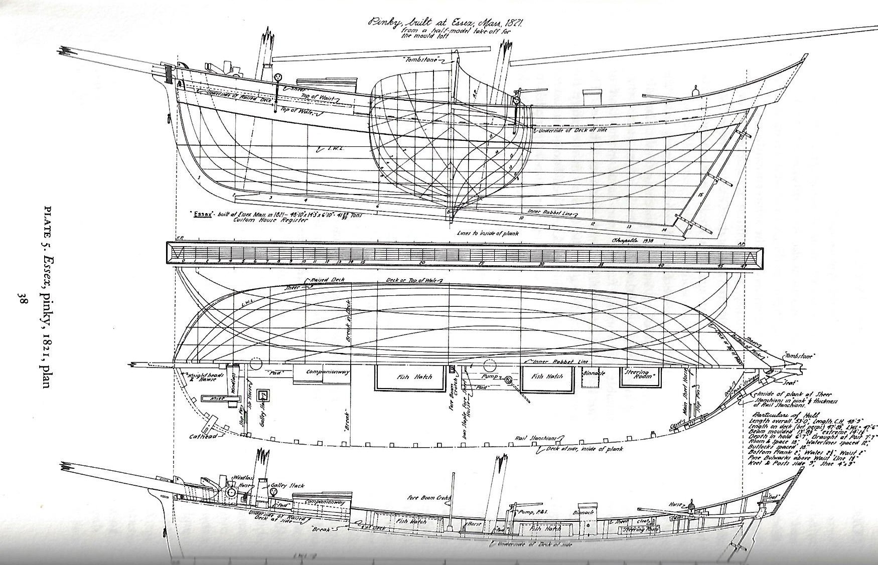
- 7
-
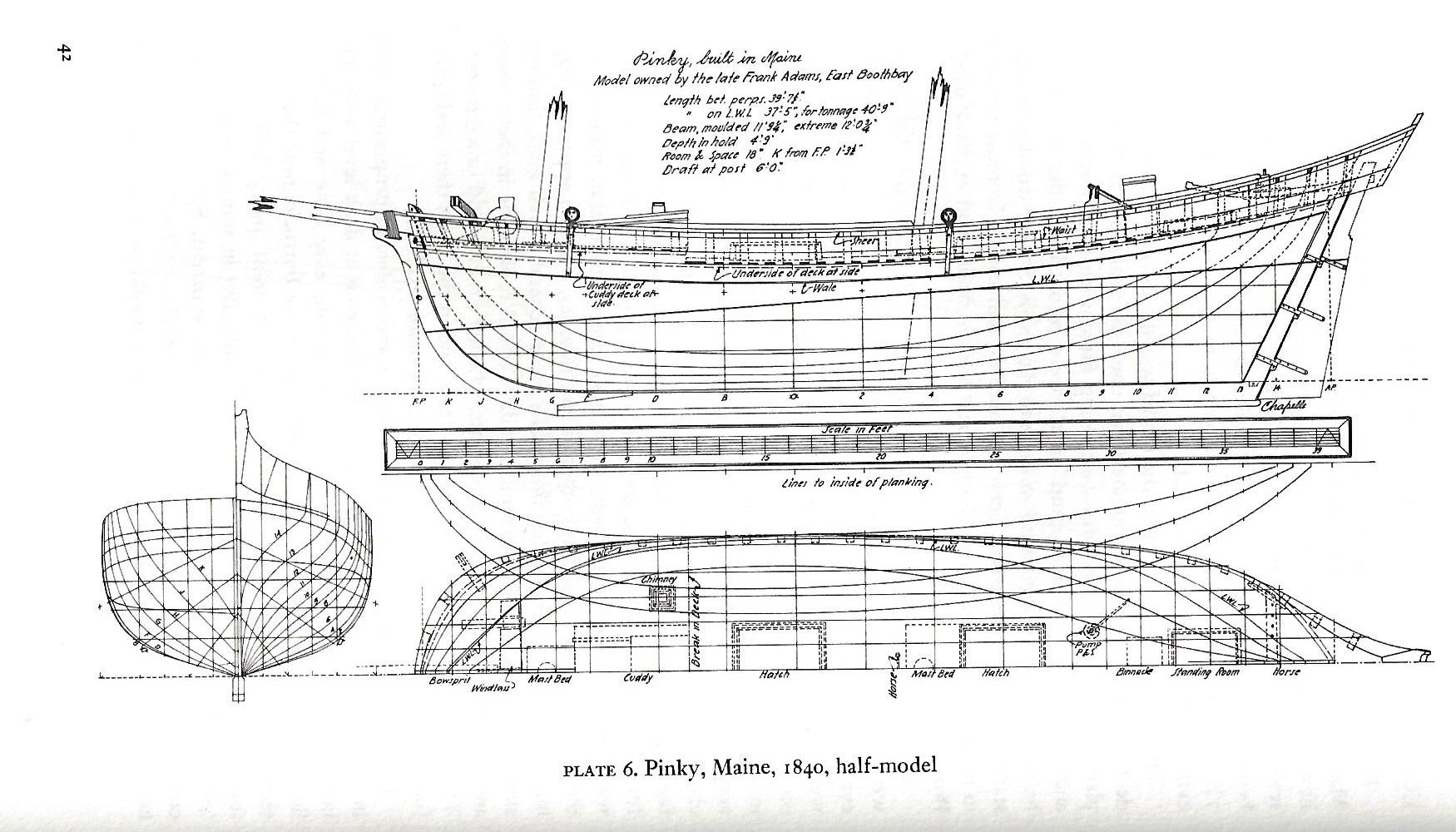
-
- diorama
- Glad Tidings
- (and 2 more)
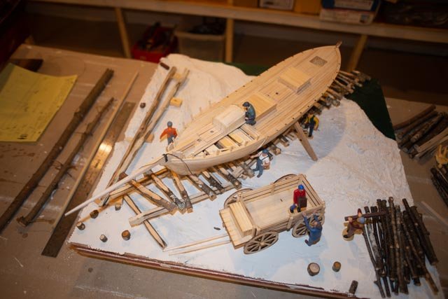
-
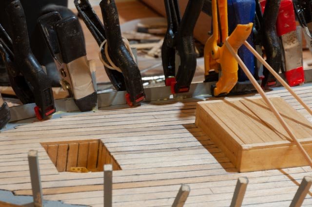
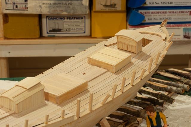
Post 16 More decking I have found, as many already know, there are a few complications to completing a deck. One needs to think through the next steps and be sure not to go ahead too far. That applies to deck furnishings, cabins etc. too. I always love to show oops too…some more are coming 126 here I found I needed to bring out the big guns…5 pound boxes of lead to hold down the stubborn deck. 127 here we set in the Samson post. I need to shape up the top of the bow stem and get ready for the bow sprit to be sure everything fits. The hawse timbers came in OK. The next planks need both weight and bands to stay down. I suppose I could us super glue, but I like the conservative approach to using wood glue for wood and it take a bit to set up. 128 here is another bad planning photo. The first two stanchions are lined up right on top of bulkhead. It would have been easy to cut out little slots before the deck. Now the crew needs to dig. 129 this is a good night progress shot a few days ago…coming along 130 I’ll finish up this week with the next oops. I put the roof planks on the companion way right over the doors. Oops the planks , except the outer ones need to cut back and the door rebuilt higher. We’ll see next time how this got fixed cheers
- 69 replies
-
- 6
-
-
- diorama
- Glad Tidings
- (and 2 more)
-
Yves thanks for the kind words of support. I hope you are half right ... the fun continues. I am sampling many different finishes today who knows what we decide. I really worry about the seaweed cheers jon
-
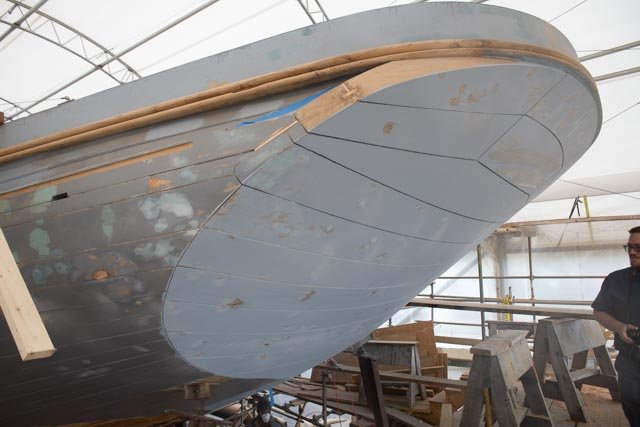
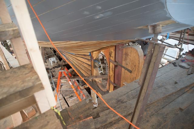
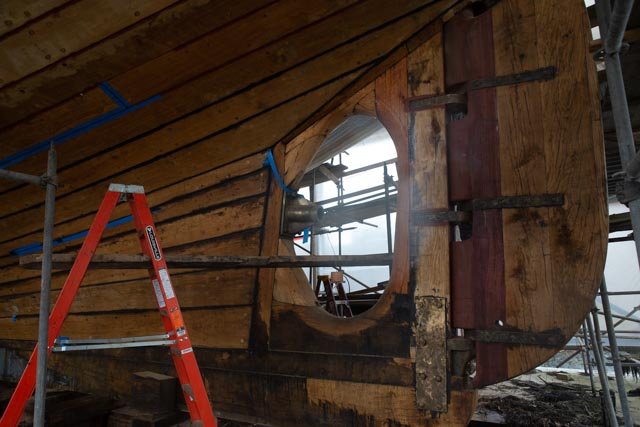
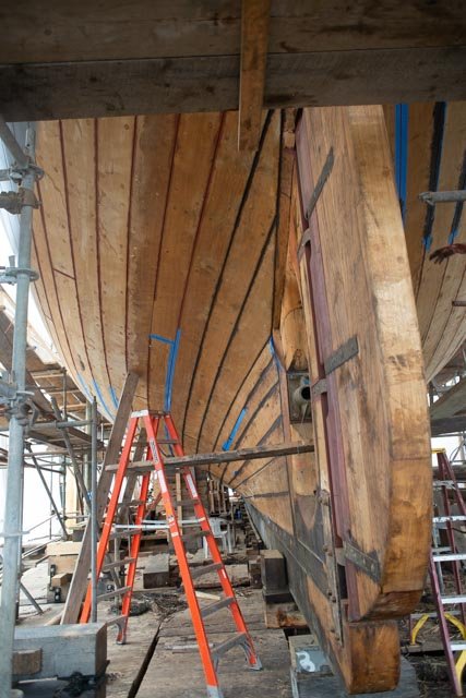
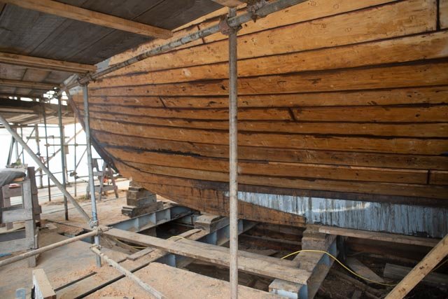
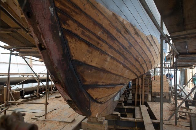
Allan thank you for this great log and providing the link source. I have never figured out how to search there........ and Bob, thank you for finding this completed log and asking the pertinent question. Effie, now Ernastina is here in Boothbay Harbor, Me in the later stages of a multi year complete rebuild. I have been on her a few times and would like to share a few views. if either of you would like to see her, I can make some contacts for you. enjoy below. i have a few more if you are interested. My focus was Bowdoin that was next to her being re-planked last year. all this photos are in my Bowdoin diorama log
- 86 replies
-
- 6
-
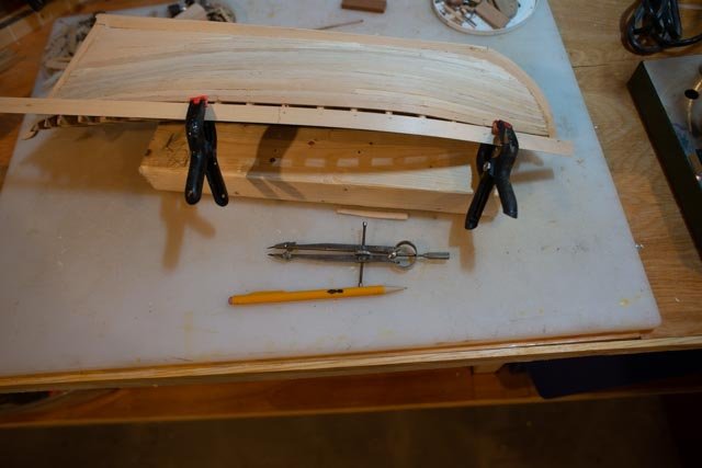
-
- schooner
- effie m morrisey
- (and 1 more)
-
Andrew I love dropping in from time to time to see this Bowdoin coming alive. great work jon
-
Eric I am happy to see this new log. I am working away at trying to create an 1816 schooner built in Maine with little visual examples. I learned of the Opium schooners by reading a great book, that I recommend for its full content, Barons of the sea by Steven Ujifusa. This story tells about the owners, the builders and the captains of the china clippers. For any clipper ship builders it's a must read. However, clearly in the portions of the book detailing the life and business of the trade, these fast schooners racing into Canton were a strong supporting character. So yes your build is a kit but the style of things like deck fittings et al will be a help to me. I also like your attempt to experiment with techniques of building planks of different woods. cheers jon
- 155 replies
-
- 2
-
-
- opium smuggler
- Authentic Models
- (and 1 more)
-
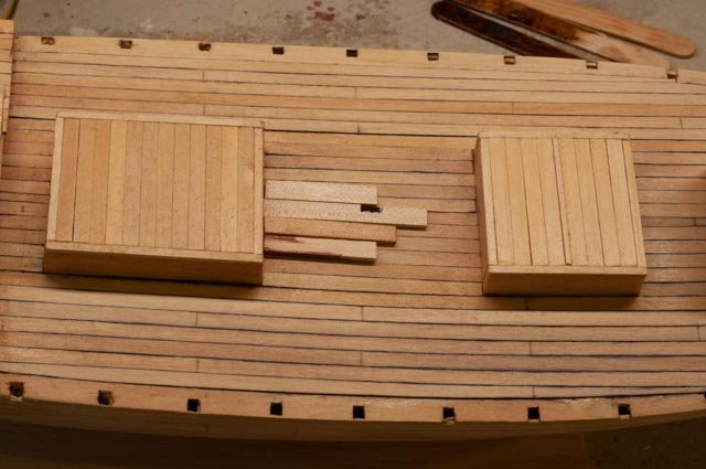
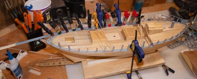
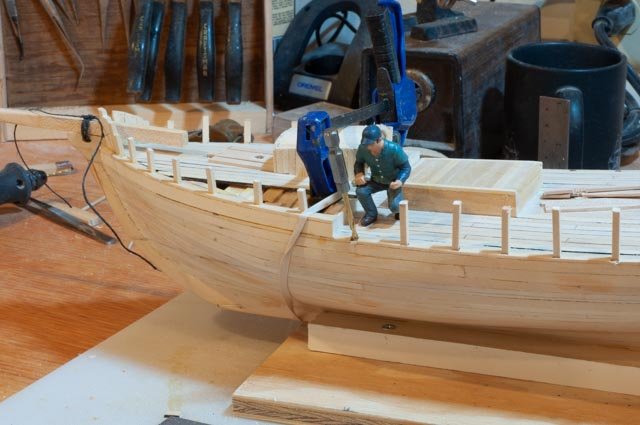
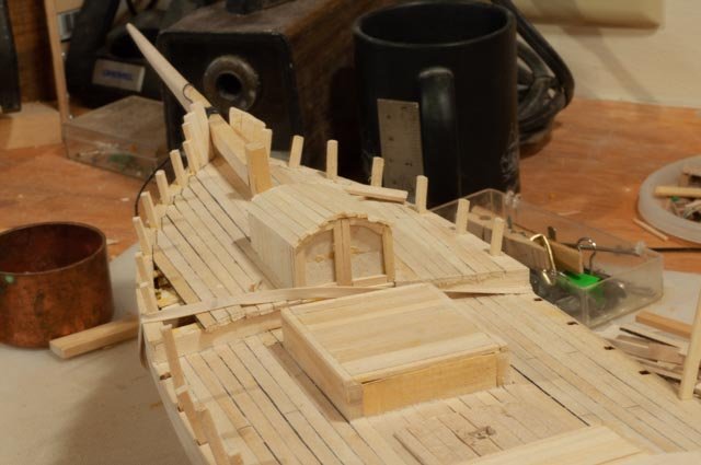
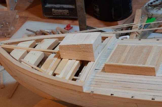
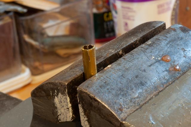
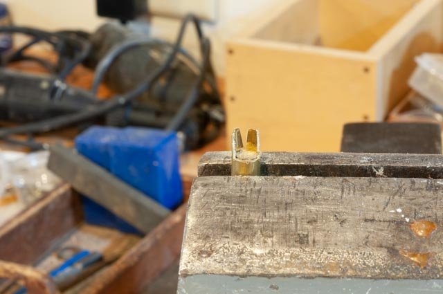
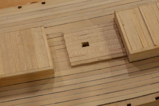
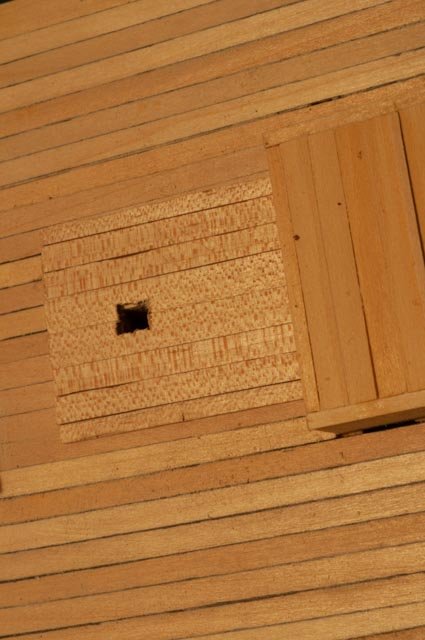
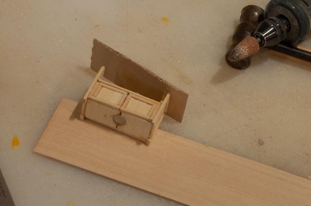
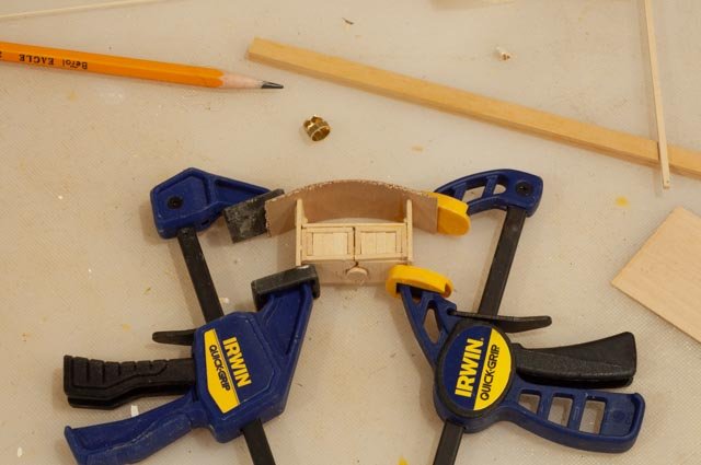
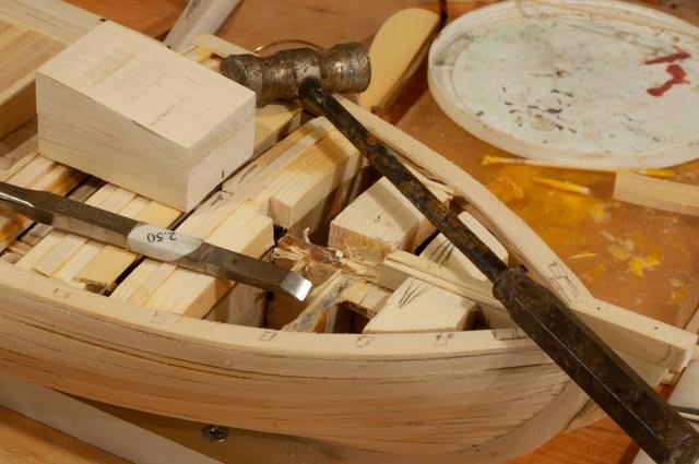
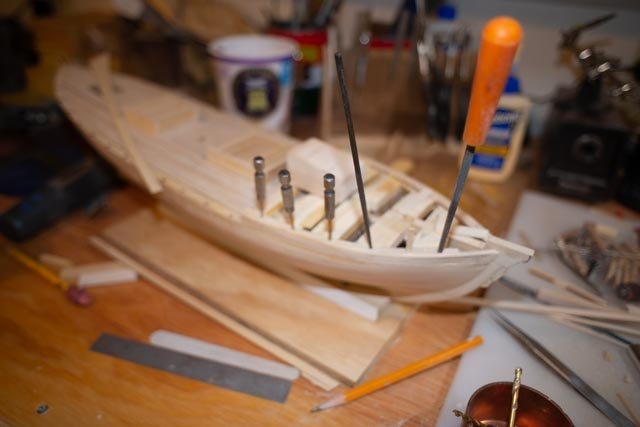
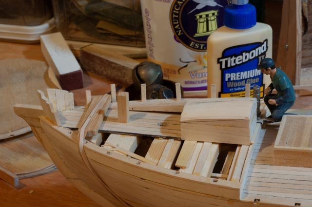
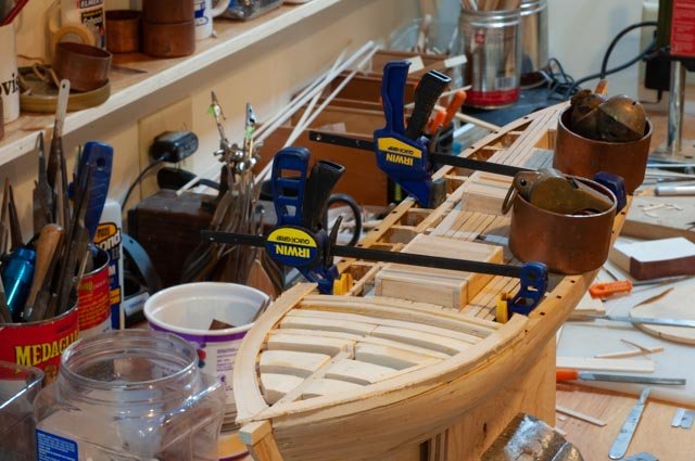
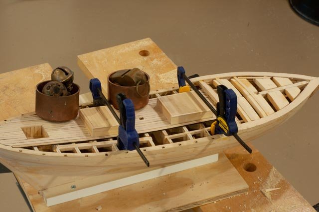
Post 15 Continue with decking as start other furniture The binnacle. What I have is a dimensional outline and many images from other builds of other period pieces. We know the top is rounded and we assume there is a compass in the upper section. It is a bit wide so perhaps it is open for a lantern or other item the helmsman would like to set down. The side view also shows it is raised on corner legs a little. Similarly, we have only an outline for the companionway to the tine cuddy cabin forward 115 here we begin the binnacle with the sides that will hold the roof and the center with doors aft that houses a compass. 116 here I cheat a bit by making a block to clad. I like maple for these inside blocks. Since there is no way to have it open on this model I am just moving ahead 117 now my first attempt for a compass. Surely it had a cover. Here is step one 118 now I cut off the front and file down the remaining cuts to make orange peels. I will bend them over and fit them onto a dowel with the end painted white with a few black lines. We’ll have to wait and see 119 now for the deck pads. I mentioned before I want livelier wood. Here I cross cut some maple and get the little spots. This is in bright light with no finishes 120 here using aperture we see the aliveness of the maple vs. the basswood decking. I like it for the feature. I fear to have ripped the whole deck in maple this way would have been too busy. I am not sure how to finish any of this yet and am beginning experiments 121 for the binnacle roof I use an under deck of 1/64" birch plywood. Here I glue one side 122 here I glue the second side. That by itself did not work. I had to cut loose and glue both sides at the same time using the claps to control the curve 123 I love sharing oops. In the blocking exercise for the raised deck, I forgot the hole for what is effectively a Samson post. 124 an experiment went well. I needed to recreate the square holes for the stanchions on the raised for deck shear plank. The sequence from left to right is hand twisting 1/16" the 5/64" the 3/32" drills followed by tiny and small square files 125 finally some visual progress as we added forward planking. Here we needed to screw clamp the hind end as there is a slight double twist in the plank. Cheers
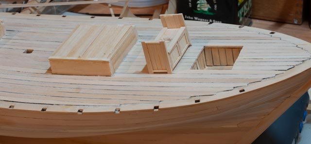
- 69 replies
-
- 7
-
-
- diorama
- Glad Tidings
- (and 2 more)
-
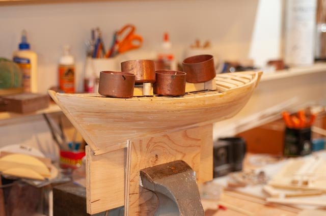
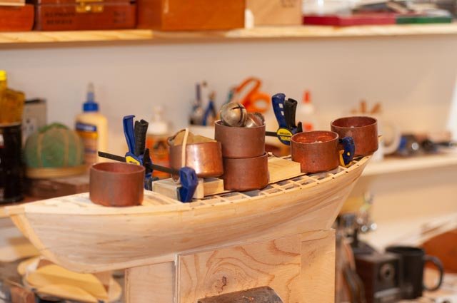
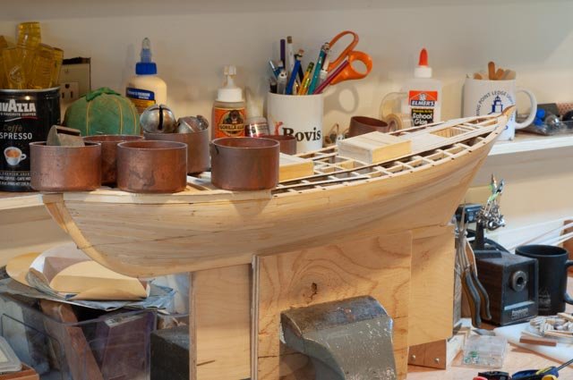
Post 14 Main deck part 1 I start this blog off sharing another oops 105 here I was going too fast forming the raised fore deck. I was laminating two 1/16” planks around blocking. You can see about an inch behind the forward clamp that both the plank rides inside the shear plank and forward rises up on the stem 106 so take her apart and do it again. I have added bands to hold down the double bend down at the stem and a clamp to hold the outer edge of the plank flush with the original shear plank. Now onto the decking. I thought about ripping some maple as the mottled look is a nice variant that might look more like the local pine, that I assume they used. I acquiesced and used some fir for the hatches to give some variation. We’ll see how it goes. Basswood is so easy to use, and just enough came in the box. 107 here we have the hatches and foot well all in, the laminated step for the foredeck done and the kit shear plank in place read to go 108 I have used these copper pipe caps full of nuts and bolts for harmless hold downs on decking before and they work well. until i hit one and it spills all over the floor. 109 here we add a few clamps and extra weight for the deep “swoop” of the deck 110 here as I complete the center planks forward of the hatch, I am also gluing down an upper shear plank on the fore deck. 111 here I am placing he first band of three planks on the main deck and you can see the roughed in upper shear plank. 112 some of these long planks needed a second go to be held down and make the slight outward curve. I also focused an making the nibs into the shear plank line up port and starboard. 113 It is time to look on the slipway as the main deck is in place and sanded. I need to complete the forward cabin/ gangway before doing the foredeck. 114 It is almost time to solve the mystery of how to finish and reasonable replicate the look of 1816. As I move into the need to solve finishing, I realize I need to make up some sacrificial parts and experiment. I have heard many suggestions. Do I use shellac and sand it to remove shine? If I used linseed oil what do I get. Do I try tung oil and other finishes. Each time I buy a new stain I need about a teaspoon and have half a pint to store. Anyway, it is a fun part to any build. I am used to using hand rub poly. I did here just for the floor of the foot well, so it does not get too dirty. I believe as i look at this view that the nicely finished mast has to go. I think a few more trips to the wood to get some small tree tops to trim down and see what we get. Much to ponder Regards
- 69 replies
-
- 7
-
-
- diorama
- Glad Tidings
- (and 2 more)
-
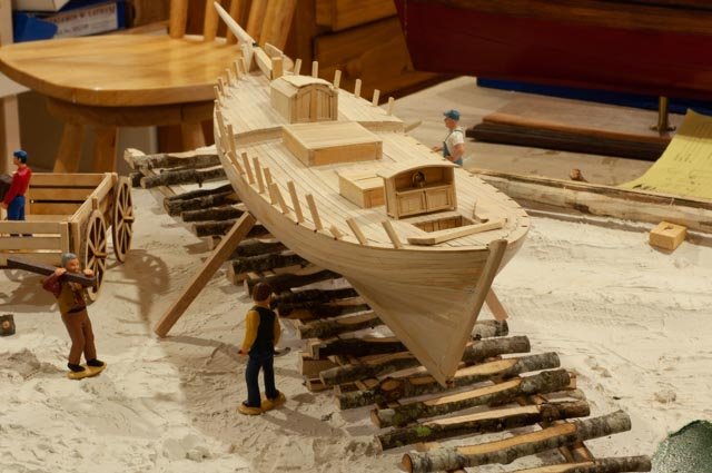
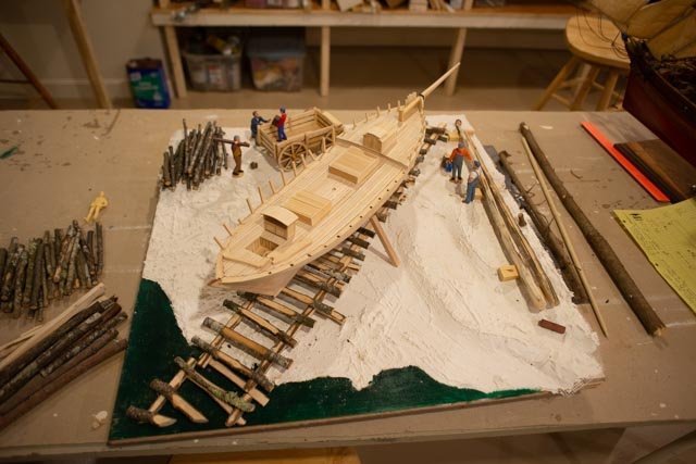
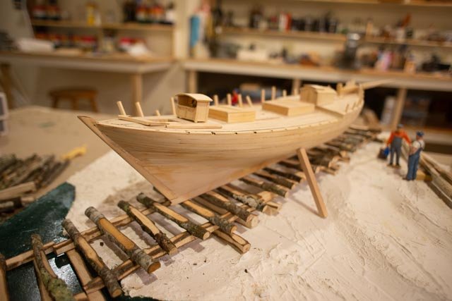
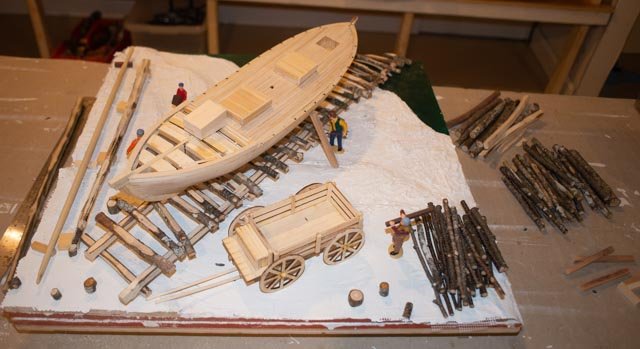
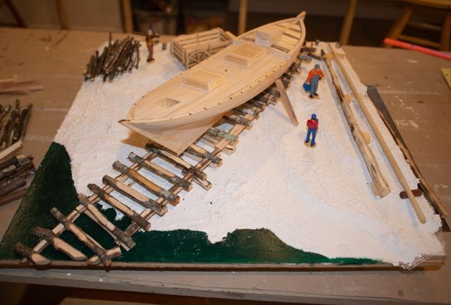
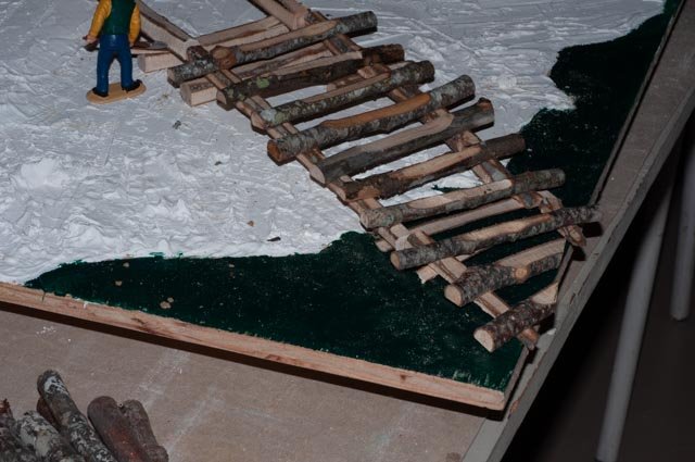
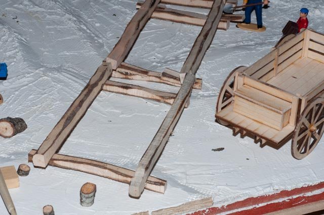
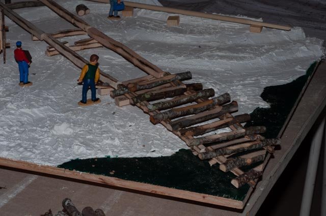
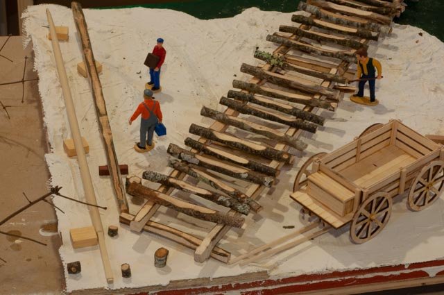
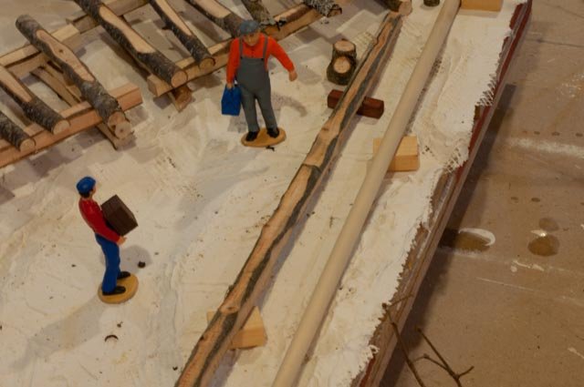
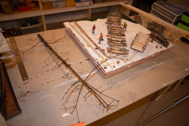
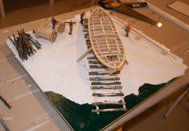
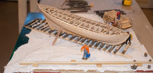
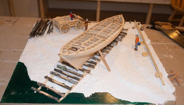
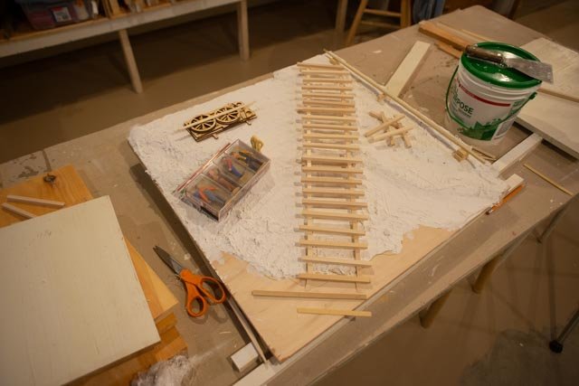
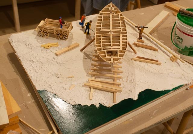
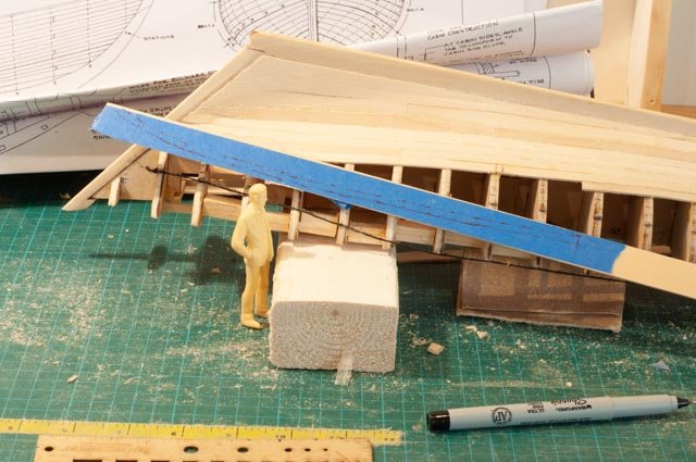
Post 13 Diorama update I need to continue with planning before I get to the final coating of plaster and painting. In this planning, I am trying to visualize what it might have been like in 1816, the year after the war of 1812 in Maine. People were just coming back fiscally. I assume that a few miles south on an island that the ship yard was pretty primitive. Perhaps this was the first boat built there. The owner builder did not stay there for many years. 98 the ways in this view are trimmed only as much as necessary. The “stringers" rails are cut roughly square but not milled. I think I am not steep enough going into the water but with the scale so big [ 1:24} I have to give on something. I have cut the ties and stringers to show the slipway headed down into the rising tide. It is nearly high tide in the moment. 99 here at the upper end the roughly squared up beams are stacked. I think the small sticks can represent the stumps of trees that would not all have been removed. If I keep the wagon, I do not plan to do much to it as I do not want it to become a feature. perhaps gray stain like weathered unfinished wood 100 here we can see better that the water comes up about two more feet at the new moon highest tides, when the launch would be planned. All these ties would be under water. So I need dried seaweed on them . wow how do I do that? maybe string or cut up elastic bands painted black? 101 back up here I brought in my first attempt of a fore mast under way. The main mast is fully shaped, on a lathes and I have to figure what shade to stain it to be a natural fir plus oil. There would be lots of knots and things. 102 this view shows with the stick I brought in from the woods is much closer to what real wood would be. The dowel in the kit is too smooth to look real. 103 I am still experimenting. Here is the top of a dead spruce that I brough in and is drying a bit before I cut it down to see if it is better looking for spars I need to think more about how the slip way would have been built. Did they spike the ties to the rails [ stringers]? Chapelle said that iron monger was easily available. perhaps they got trunnels and drove them home. Hackmatack trees were common in a few areas up the tidal rivers, and for modeling that could be done with toothpicks. Either way I believe I need to square the whole top of the ties and do many more so I can better gauge their more consistent size. As soon as I figure that out, I will go with another layer of joint compound. I then need to think about embedding pebbles and stones. Unfortunately, they are frozen in under snow and it is only 16 degrees today. I need to get some different sponges to see what works for seaweed too. Cheers
- 69 replies
-
- 8
-
-
- diorama
- Glad Tidings
- (and 2 more)
-
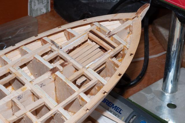
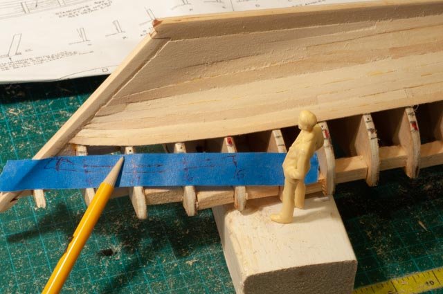
Post 12 Raise the foredeck frame the hatches I love experimenting. Sometimes it works. Here I need to raise the foredeck and extend the bow stem to follow the original design. Before moving on two points that were in the camera and not posted 91 this shot just shows the back and forth methods I used to get those lines transferred from one plank up to the other. Here I used tape holding the back with my finger against pressure of the compass as it extended above the bulkheads. This view shows that for a scratch build, one might run the frames or bulk heads up beyond their true height to give something to hold the tape or card stock being used to transfer those lines. also in the lower left I think the repair of the short plank came out ok. i will need to cut in the joint 4 planks below that, where I ran the plank through to avoid the same problem. The bits of fill are where the clamps did their damage during glue up....so much more to learn. 92 here I had an old devise intended to transfer lines to the side of frames to use for the waterline marking. I will do it again later so for now just a light pencil line so I can consider what and how to finish the outside. 93 here I used my iPhone to photo the bows of the 1821 schooner above and the 1939 Glad Tidings below. The two obvious differences are the raised foredeck and built out stem to support the bowsprit. 94 so here we go. I learned the hard way to add on much more than you need in the end. Much of this piece will be sanded off to get back to the right line, and I think we need about half of what I added. 95 Here I am doing four things in an effort to make the bow more line 1816. 1. First I soaked some 1/16 planks and am bending them to dry to the shape of the curved shear plank. 2. I am installing blocking to build up the fore deck. About ¼” at the step to 5/16” at the bow. 3. I am laminating 4 each 1/16 planks to form the step. 4. I have inserted a horizontal piece for the stem. I did this as it will be stronger. If I had planned for this stem from the start, I might have altered the kit stem to extend upwards. Perhaps another lesson learned. We’ll see how this looks. If the horizontal joint looks funny, we can solve by painting the stem. 96 here we are gluing two laminated 1/16" planks around the edge to make the raised foredeck. This is an experimental process as I will need to sand this in the horizontal plane to make a bed for the raised plank shear. 97 here working aft I have redone the framing for the revised deck plan and put in the standing well sole. I used black marker on one edge and applied rub on poly, so it looks like new pine that was used as it is harder than cedar to stand on. You can see the added framing to reduce the size of the well, hold the binnacle just forward and the added fish hatch before the binnacle Cheers
- 69 replies
-
- 6
-
-
- diorama
- Glad Tidings
- (and 2 more)
-
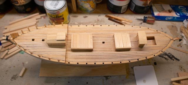
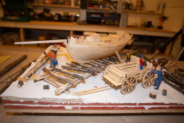
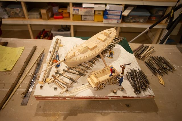
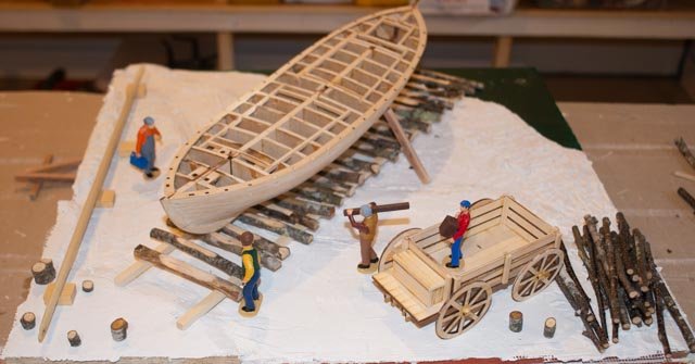
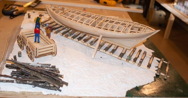
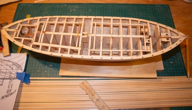
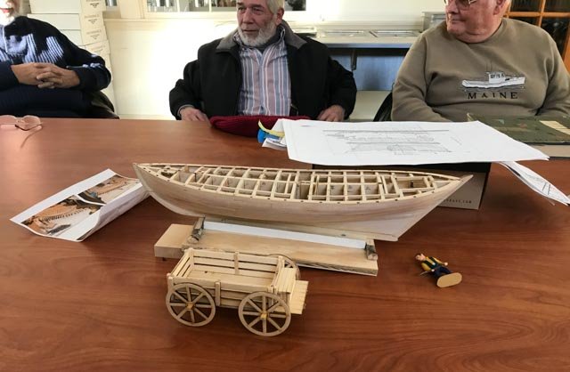
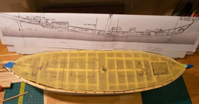
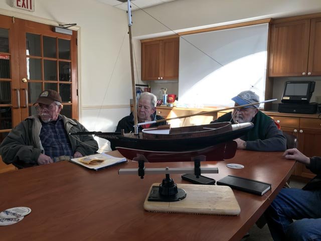
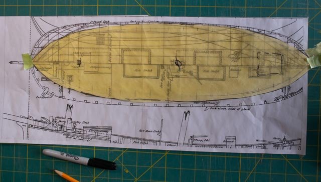
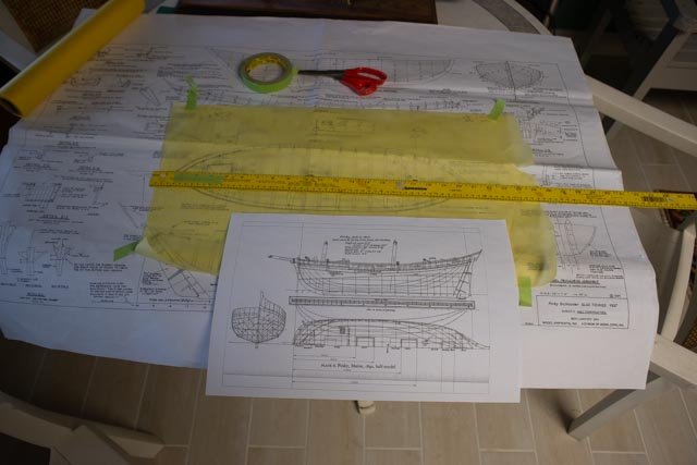
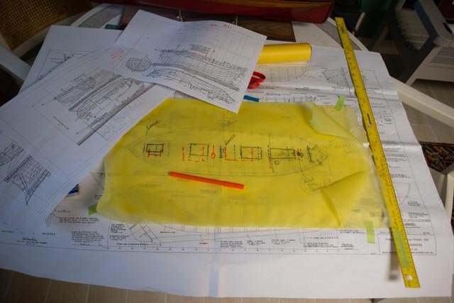
Post 11 More planning for diorama and deciding the deck design It is time for our first guild meeting for 2010. This also marks a count down of sorts. I need to use these 5 monthly meetings as milestones to get this all figured out and done in time for a Memorial Day weekend opening at the museum store. So lets put things on the table and see where we are for the overall diorama. 82 here we are looking straight on. I am thinking to have the supplies and wagon over on the left side. I must get another figure or two and then decide what will be the action. Options include mounting the rudder, adding copper, perhaps working on deck. 83 from this angle I think there should be on going work on the spars 84 I am not sure what to do with the wagon. I may have coils of cordage and stuff that came from town 85 here is my current wood pile form the woods. I have started using the material for the “ties” -ways. I need more bigger ones for the “stringer”. I need to learn the vocabulary for the works in the ship yard 86 here need the post I am thinking of the scaffold / ramp to get on deck The deck design 87 what you see here is the deck preparations I made following the plan for the kit. There are two cabins. This all needs t be adjusted. The laid-out planks are for the decking. My guess is the prolific eastern cedar would have been used on such a local boat. 88 here we are at the Downeast Shipmodelers Guild monthly meeting. I went through the plan showing the three designs and got some ti[s. a general consensus was not to worry too much about exactness. Since the bow is tight I will be forcing the foredeck [ reducing the windless to fit] and there was a nodding of heads. One comedian suggested I bondo on in globs to bring the bow out to the correct shape. 89 here next to me is a beautiful Bluejacket friendship sloop. All of us applauded the work our new member has done completing this model. 90 finally we are back from a weekend to the kids [ to avoid xmas travel dates] and sitting back in the chair with a resolution for the deck design. The printout is same scale 1821 Essex Pinky that reflects most of what I am doing. The yellow tracing shows the combined work to locate the deck furniture. I think I am going to reverse my previous decision on placing the pumps aft for two reasons. The large binnacle takes up critical space just forward of the steering position. The pump in the 1821 version is close to the main mast. This is common on ships of the era too. It was the 1840 and onward schooners that show the pumps further aft. The deepest part of the hold is also right aft of the main mast. There is a raised wooden double decking around the main mast through which these pumps would go. So, using this section as my justification, I will place the pumps in the forward position. Next up, I am cutting up the tops of the bulkhead and added supports for the hatch work, and building the bowsprit
- 69 replies
-
- 6
-
-
- diorama
- Glad Tidings
- (and 2 more)
-
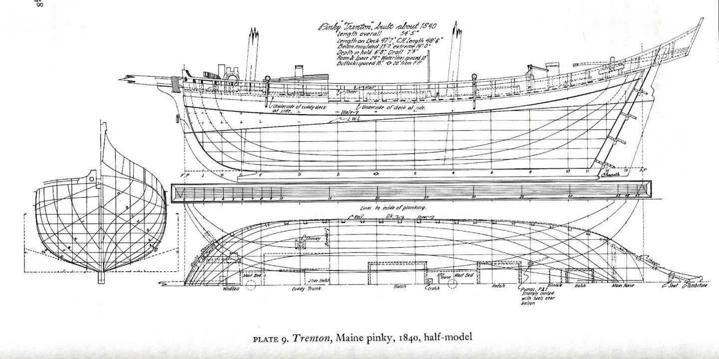
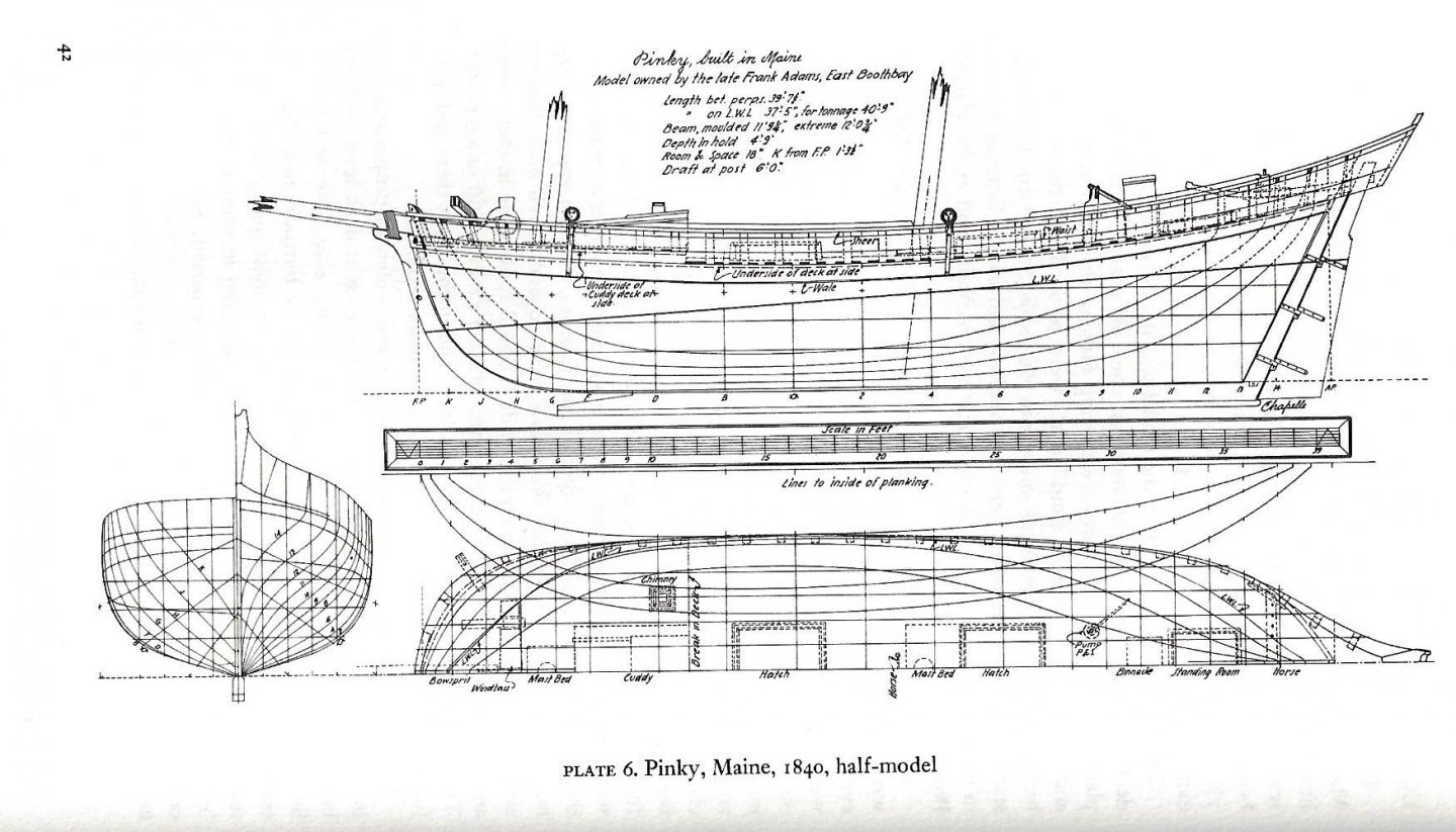
Post 10 Deck planning Like many tough decisions a few days is sometimes needed. During this time I got the shop floor painted , moved more boxes and stuff around and went to see the real boat where we are having the bottom taken down through 22 years of bottom paint to the gel coat. She was beautiful. Now to superb or the first pinky in Maine or as we are about to decide the place holder for the first Pinky in Maine 81 here is compilation of three schooner deck designs. Through the wonders of CAD I have · on top or the starboard side the 1840 half model from Adams yard in East Boothbay · on the bottom or the port side, the 1821 Essex built pinky. · the yellow tracing is the Howard Chapelle 1939 deck plan that is the basis of the Glad Tidings kit. There are a few subjects to review and then the rationalization of how to move forward with this build. 1. It is obvious to anyone that the hull shape of 1821-1840 is almost identical but different from the 1939 cruising version. It is indeed quite pronounced. I can not try to tell anyone that the hull I have built accurately reflects an 1816 built schooner. I will need to find some explanation to include in the display to downplay this distinction but for the record the difference is there. 2. Cuddy and masts: Chapelle history included the Pinkies sailed further and further as years passed. The crew after 1840 reached seven. Thus, it seems obvious the 1840 plan has a larger cuddy cabin with a fixed chimney. There was apparently a large water barrel kept on the opposite to the chimney. The 1816 version I suggest would be more like the 1821 Essex with a smaller cabin. crews we often three. the chimney was removable and wood. That also means both the deck rise drifts aft a bit as does the mast from the 1840 version. In both versions the foremast is forward of 1939 Glad Tidings. So the main mast seams fine but the fore mast must go forward about ½ inch. looks like a drill job. 3. Hatches I am less emotional here and for no other reason that consistency will follow the 1821 design or port side. 4. The foot well. I will keep it inside the black marks, which indicate where I am with the Glad Tidings model. I will respect the smaller sizes and square it up too 5. Now to the pumps. 1821 Essex showed them near the main mast. In both examples for 1840 they are further aft. If one takes the cross sections provided on the plates, one sees that the lowest area of the hold is all along the aft fish hatch. I measured the drop from the Glad Tidings deck and found the line where the hatch will go is the deepest. A question I can not answer is do the two fish hatches lead to the same hold or are they separated. Thinking 1820 I can believe it was one big hold and the pump was located just aft of the bulkhead. The fish hold included the main mast. I looked at 4 other plates of similar boats in the Chapelle text and the pumps were more often aft. I will look a little more but for now they go aft. I need to think some more for a final decisions. I’ll let the floor paint cure and resort the shop. In the meantime, I will get the shear planks on and think about sealing the planks. I am still debating if the hull is all painted out at the time of the scene. I was in the woods this morning collecting small branches to see about making a more realistic slipway and scaffolds. I doubt they had perfectly milled 8-inch beams and planks to build the slipway 5 miles down the coast on and island. Sawmills were around for the schooner parts but the slipway had a short lifespan. All for now
- 69 replies
-
- 5
-
-
- diorama
- Glad Tidings
- (and 2 more)
-
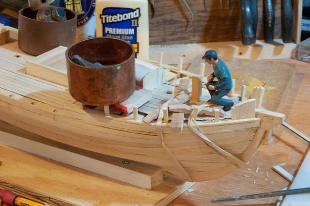
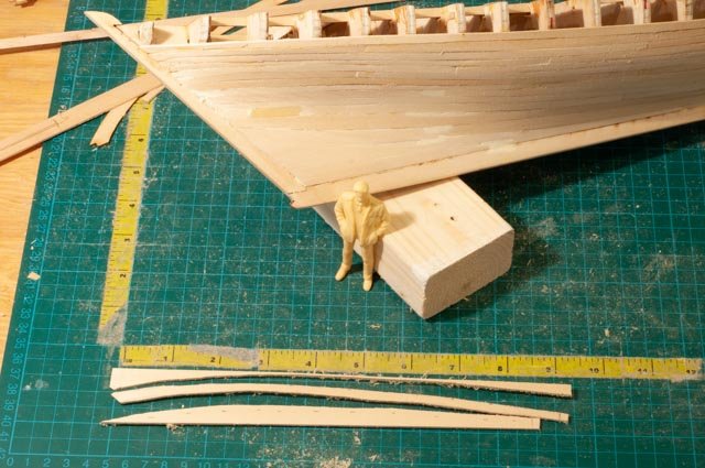
Post 9 Our whiskey plank, the crew starts to arrive and the deck study I am writing this to see if by doing so I can decide a few key items regarding both the diorama and the deck. Planking finish….I did not make 17 days. The results i feel are better than before and that is all I can ask for. Each model gets better and better. Regardless there are no more planks so a wee dram is due this evening. 75 here we are doing the top port side plank. 76 and here we finally got there, it is our glue up of the last plank on Starboard. diorama So what is going on with the diorama planning? 77 today both the first of the crew showed up. Thank goodness for ebay! They also brought along a farm wagon kit. Considering the actual site of the first build was not in town so to speak , I presume some type of wagon would likely have been needed, we’ll see if it works. 78 it’s late in the afternoon, sanding the hull is mostly done, so let’s see what it looks like on the ways. Also the first paint to show water. Deck planning This is a first pass. In early posts I commented that I am using this hull to get there. It is not in itself a copy of 1820 but a compilation developed by Howard Chapelle after his many years of study. Thus, the length of this hull needs to be used in reviewing alternate lay outs. To do that I have taken the three plates provided by Howard Chapelle, scanned them and put them into Turbo Cad…..my retiree budgeted $150 program as auto cad is too $$$ and Turbo cad does everything I want to do at this time. I scaled each plate, so the length of deck was a similar, 19.5 inches to Glad Tidings, and added dimensions to all the pertinent deck features. First I traced the shear plank on yellow tracing paper the Chapelle Glad Tidings plan as that is what to have built. 79 here, on a tracing overlay, I have taken the first plate, scaled it to the same length and printed it out a ½ scale so it would fit on one large sheet. I tok the pertinent dimensions of masts, bits, fore cabin and hatches etc. and marked them on upper tracing sheet and color tagged it. 80 here we have the results of all three plans color coded, so we can study and figure out what we are going build. Before we go forward, we need to decide a few more things. 1. All three plates of the 1820-40 pinkies have rounder bows than the 1939 hull that I built. I can't do anything about that, we just need to record it. i will make a drawing showing the difference, it is not significant but visible in the plan view. 2. All three plates have the foremast moved forward between ½ to 7/8 inches from Glad Tidings location. 3. Two plates agree and one moved the main mast forward. 4. Hatches are different and the foot well is different for each plate. I have not decided a final layout, but the 54 foot Trenton scaled down just does not line up with the others and I will throw it out. The 1821 fits nicely with The Glad Tidings dimensions with a little adjustment. The main mast is right, the foremast needs to go 1/2 inch= 1’ forward and the foot well just gets smaller. so today is to celebrate the last plank, the crew arrival and I hope a plan to design the deck layout cheers
- 69 replies
-
- 5
-
-
- diorama
- Glad Tidings
- (and 2 more)
-
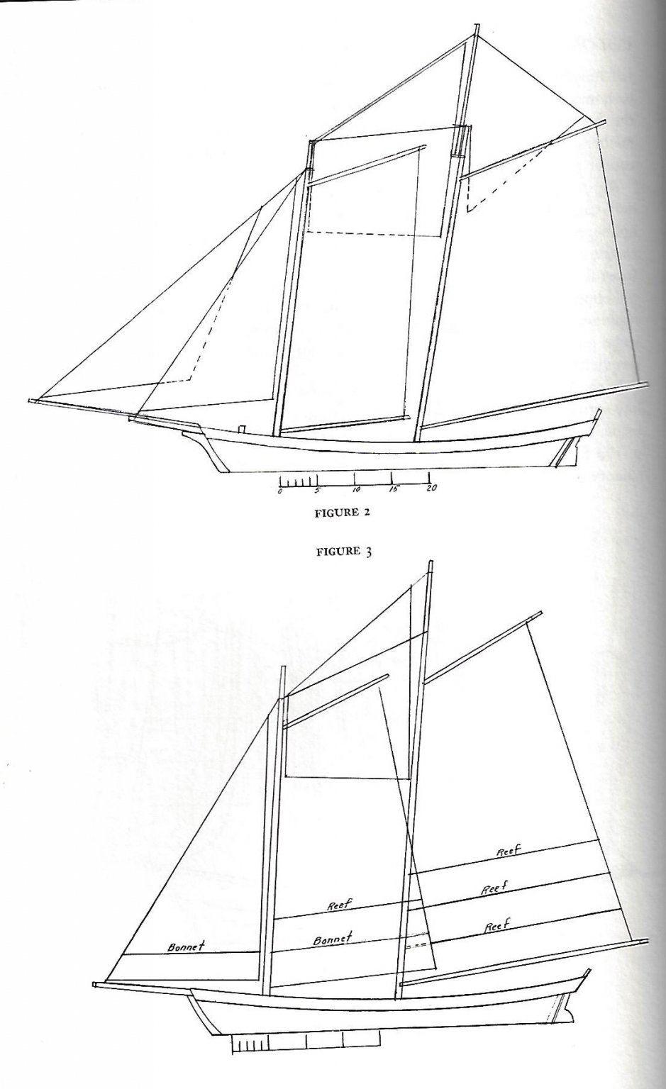
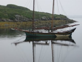
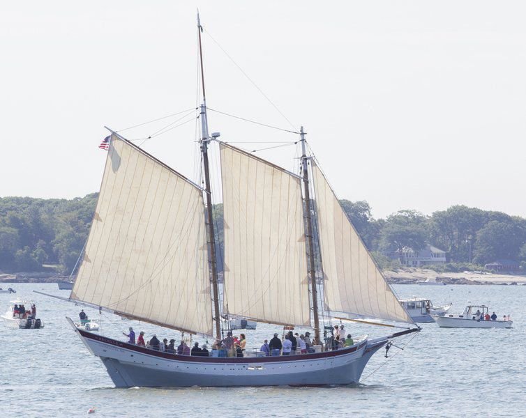
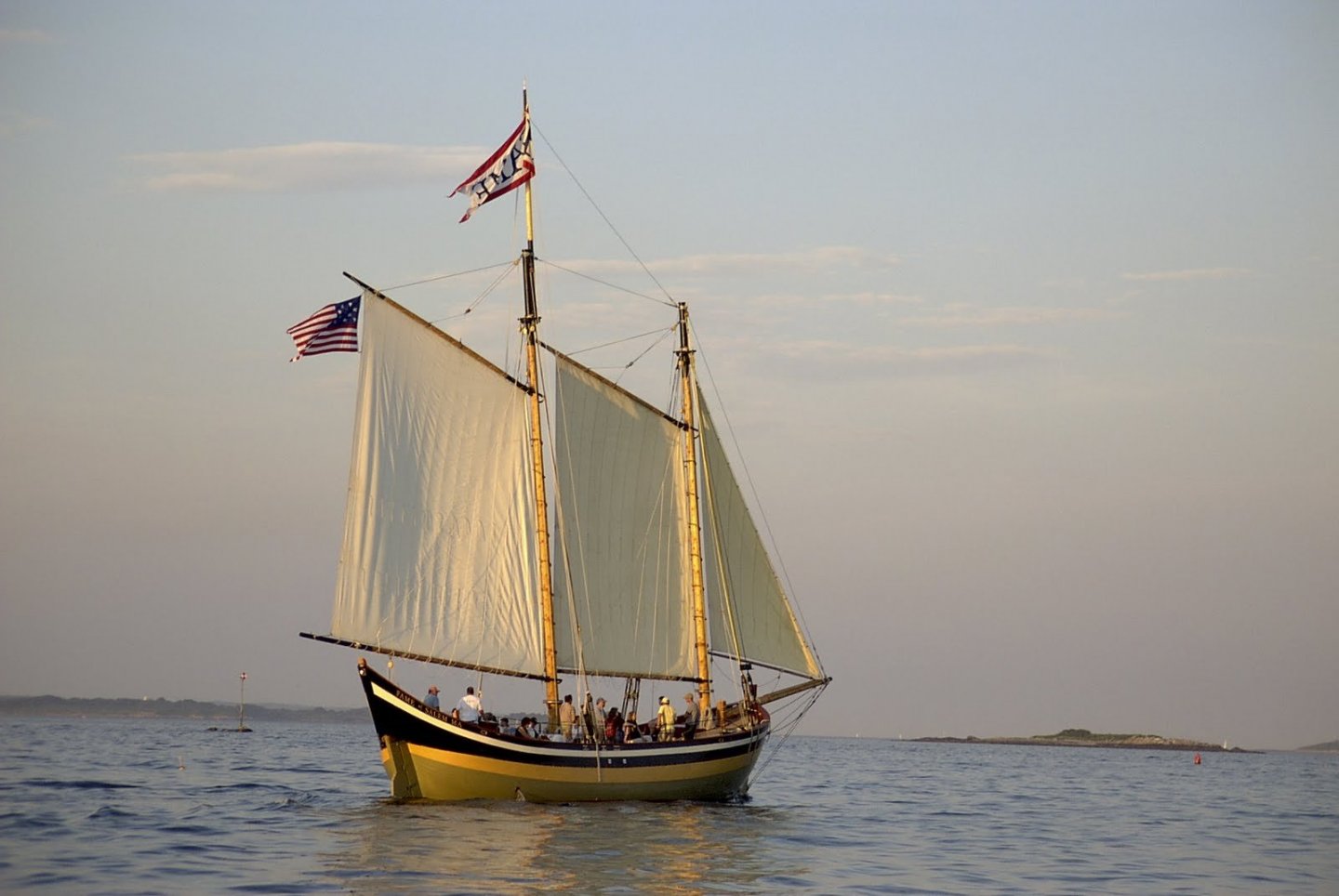
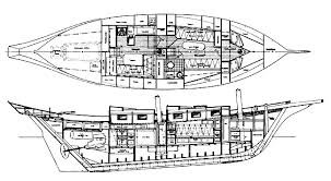
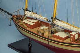
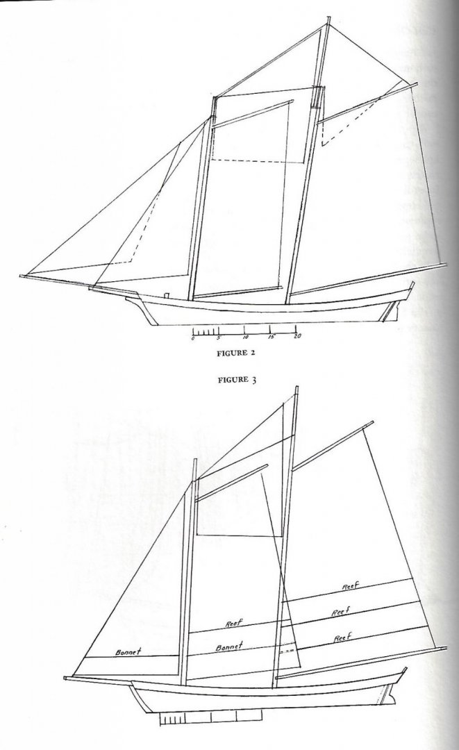
Post 8 Time for some history I have been rereading The American Fishing Schooners- 1825-1925 by Howard I Chapelle. I would say this is a needed read for any schooner modelers, and it must be in just about any library. I am proud to say Pinkies fill up chapter 1. I will not try to repeat much of what Howard shares but focus on the parts that link to my project. The process of pulling together my notes and writing them here actually helps me in the process of deciding what to build and what story to prepare for the talks and story boards to accompany the model next summer. We have a college student who is willingly going to plow into the Hodgdon family story and tell about developing the mill and adjacent boat yard. Our project last year shared the build of third generation Hodgdon who built the Bowdoin in the same yard one hundred years later. I mentioned earlier that the base design for the build is use of Howard Chapelle’s 1939 plans for Glad Tidings. Here we need to determine what was different one hundred years earlier when Pinkies were for fishing and not carrying tourist on harbor sails our distinctive owners on brief cruises. The obvious distinction will be on deck. One of the interesting subjects was that pinkies were used for both fishing and freight. Their key characteristic was their good sailing into the wind. As those of us lucky enough to sail here in Maine we know well what that means. In summer the prevailing Southwest wind makes traveling southwest along the coast very difficult. We fair weather sailors pull our boats in October as the temperature goes down, sundown comes early, and the winds pick up more speed. The early Pinky sailors continued well into winter. Thus, the high stern to protect the helmsman as they run down wind. 67 Here I share a few images of recent rebuilt tourist Pinkies. There are many online. This one I believe is Ardelle built in Essex. Many articles about her..a great story 68 Her is Fame . Note the bright colors, the swoop of the aft ‘pinked’ stern and simple sail plan. With all fairness to the rebuilders we need to look back before selecting our finishes. As I posted earlier, think simple black, some green and yes copper bottoms. Today they all have higher tech paint. In some reading I did last year about the 1850 era, I found paint in those days were linseed based and offered no antI-fowling help. Coppering I have read was very common and for a successful landowner and owner builder like Caleb Hodgdon he would have understood that value. He kept Superb for many years, so I am making an assumption that he had a copper bottom and he did it himself. We know Red Jacket was built about 50 miles northeast of here, and she as well as other bigger ships got their copper overseas. I may be crazy but I feel a 42 foot Schooner could easily have been done in Maine. This assumption is just that, and I would love to learn more about these finishing processes as we go forward. 69 Here on a few of the many visuals of pinkie plans on the net we see the introduction of cabins. Let’s face it, fish did not need a cabin. We need to look further. Glad Tidings looks like this one. 70 here is an unnamed model I found. It might be Fame looking at the coloring. Anyway the point is that there is a main hatch, a small forward hatch and a forward cabin. Chapelle talks about the variations in the forward cabin. The variation were based on cost and timing. The earliest had wooded chimney and it was years or perhaps money that brought the cast iron stoves aboard. As we got later in the century, I have read many stories of the Pinkies leaving here and neighboring Southport Island and sailing to PEI by going around Nova Scotia to fish for mackerel. The Pinky for that trip would need the forward cabin to accommodate over night and cooking and staying warm. Chappelle plans from his book. The American Fishing Schooners I include here scans of four of Chapelle’s plates. These with the accompanying text will help me solve the deck plan. 71 first is presented as a 1821 Pinky from Essex at 48 feet. That is about 6 feet longer than us. What I like most is the two fish hatches and small forward cabin. It may be the extra 6 feet that gets two hatches 72 this is 1840 and 54 feet. Clearly there are tow hatches and the forward cabin is clearly longer. I assume for a bigger crew 73 here we have the most interesting. The story is it represents an earlier than 1840 Pinky model owned by Boothbays Frank Adams in 1937. frank said it had a wood chimney that was removable . What I know as a Boothbay resident is that the Adams yard is literally next door to the Hodgdon yard. Today it is shipbuilders park. It is where two four masted schooners were build in 1890 and 1903. The length is 39’7” That is very close to what we are doing. Caleb Hodgdon, our subject builder brought Superb to East Boothbay, bought the tide mill, stared sawing lumber, invested in near by land and built his first pinky there next door. He build Pinkies in 1823 maybe there and definitely there in 1824 . There are most likely many similarities in these old schooners. My take is to follow it; there are two hatches and a small cabin. I think the two hatches is realistic because the boat was kept by Caleb Hodgdon for many years. He was not a fisherman. It surely did go for mackerel as the schooling was a big deal here in Gulf of Maine. But it was seasonal. So…. take a load of fish to Portland and bring back trade goods. 74 is interesting as it supports some good explanations in the text. The 40 foot Pinkies were three sail schooners that three men would take out for several days all year long. Our winds and seas are rough outside of the July august warm months when they slow down a bit as the water warms up. They did reef etc.as they sailed all year long. the need for top sails was limited to summer light air. He shows the main top staysail, called fisherman staysail on a Bluenose. the success and popularity of this rig was apparently great ability to beat up wind against the prevailing winds. One does not need topsails for that purpose unless very light air. One need to keep the boat flat as they did not have very deep keels as a racing hull does. Anyway this rambling is getting me ready to lay out a deck plan. The text in the book talks about the ease of getting iron works and the various designs of horses. They were a combination of wood with iron reinforcement to straight iron on the foresail of forestaysail. I need to study that more to decide. Also, I find it curious that only one dead eye is shown for each mast. The new rebuilds sailing today have more, but that could be all about coast guard requirements and cannot be a test. Even the great Bluenose II has an extra Main top shroud to satisfy the coasties. All for now

- 69 replies
-
- 4
-
-
- diorama
- Glad Tidings
- (and 2 more)
-
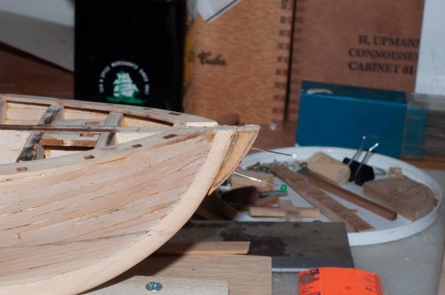
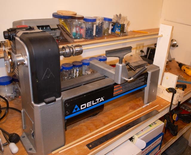
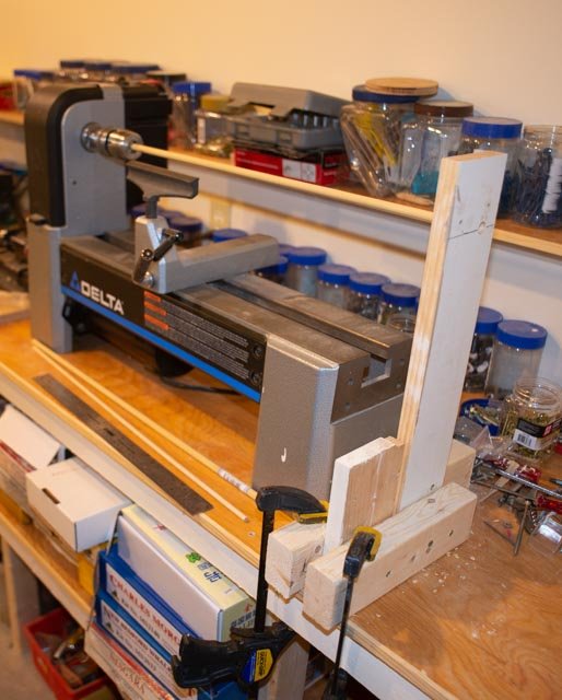
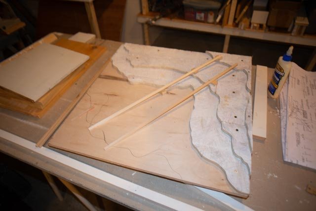
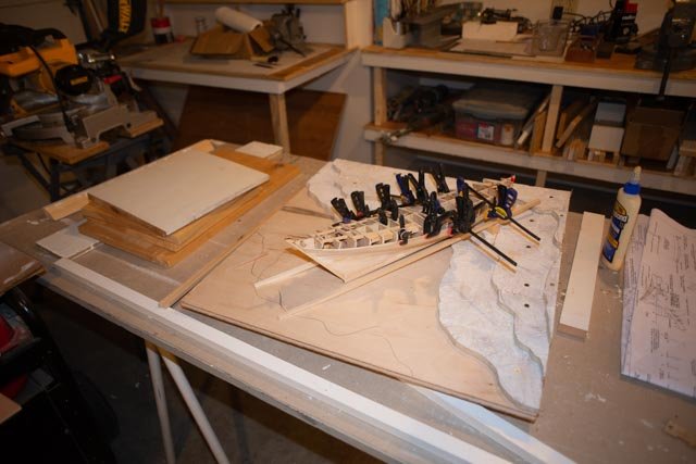
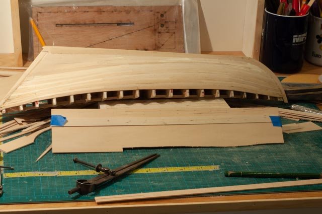
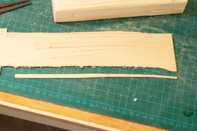
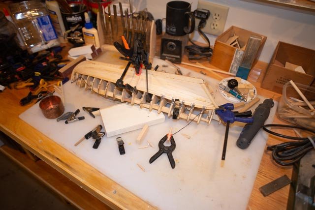
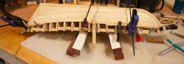
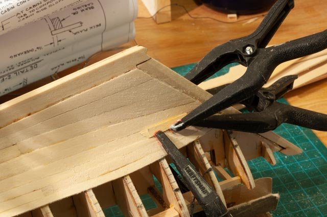
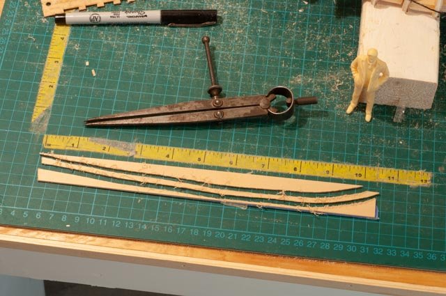
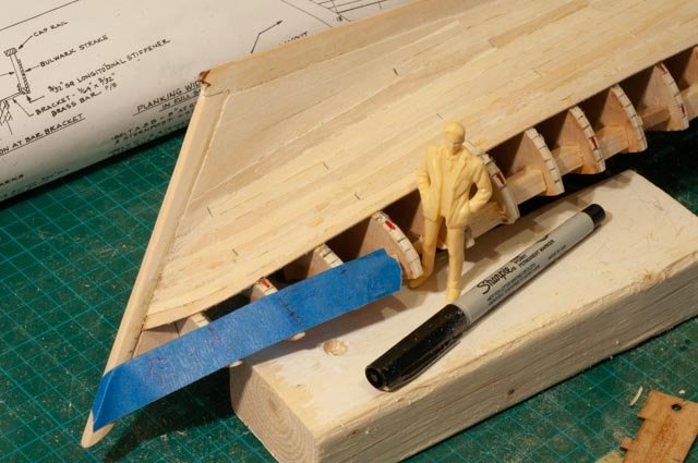
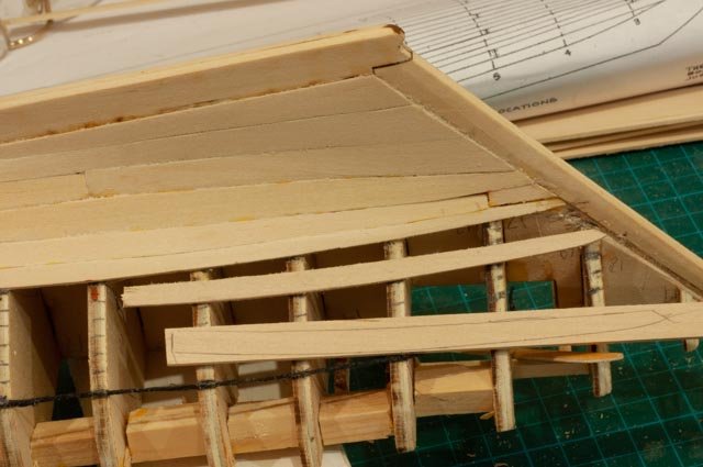
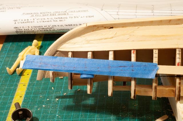
Post 7 Planking part 4 getting near the end Now that we are getting near the end, and now that needed daily shop building work has drifted into the background a bit, I thought I would end this year with a flurry. As in the past, I need to be doing a few different things at the same time. Below I have started thinking about the diorama, started the spars, continued research into a 1816 version of a pinky and continued planking. Diorama The size of the diorama needs to remain the two-foot arena. I have a left-over piece of Birch plywood and several sheets of ½ inch chip board that are perfect one-foot lifts in scale. The actual site of the actual build is a cove area on the Westport Island, which is not far from here. The selected area would have had a gentle approach to the tide and land side as one must assume wagon access at least and ease of launch as most important. 53 here is an overview of the three-foot lifts cut out to receive a runway that fits the schooner. The kit conveniently provides a supply of extra wood to build ways. After completing the lifts, I placed the model just to look. At the idea. I think I can make this work 56 back to build up the ways and “runway”. The dark pencil line is the tide at the moment of the scene. It is near high tide as with 9-10-foot tides we need to consider the edge. I am guessing a bit as to what was done in 1816, but I assume the wood runway would have been placed at a lower tide far enough to get the schooner in three plus feet of water at high time. 57 We must also decide where is the schooner is being built with respect to the tide. They also would not want the water under foot twice a day as they were building. Also as to selecting the site, it is most convenient if the pitch of the ways makes the deck level….. Something to study when we go to East Boothbay for the second build where more focus will be on the land side. 58 how to build rocks and seaweed?? I am not sure, and this is truly an experiment. I like the ease of working joint compound instead of plaster as it is much more workable. I used up joint tape as a media over the hard lifts and applied a rough coat. 59 here I am doing the same to the remainder of the land side....I’ve nothing to lose except left over materials, so let’s just do it. Spars 54 now for our spars. I have a midi lather [ long story as to why] to build longer spars I need to rig something to hold the spar. Here a simple temporary bracket clamped to the bench 55 I wrap the end of the spar with electrical tape to loosely spin in the hole and focus the tapering at the business end of the lathe. Buying a set of chucks to fit dowels was a great aid in spar making as the ends of the dowels are not damaged as they would be with say three or even four pronged chucks Research I don’t have visuals yet, but I am re reading Chappelle…The American Fishing Schooners 1825 to 1935 and he had lots to say about Pinkies. I can say for a start that my following the kit design for deck house supports was a waste of time because all of his presented plans show a very different deck plan. This is going to be fun…… fortunately, the recessed cockpit did occur in the earliest designs and was needed as a foot well. Anyway much more to come on that review of the deck plan Back to planking I said a few things so far that turned out to be wrong….not surprising . It does matter which sequence one takes on filling the bands. I assumed that bending and holding planks on the center band after the outer two were complete would be very difficult. Well by working steadily down as I am, one runs out of bulkhead long before finishing, so accurately measuring the planks become difficult. Thus, the right comment would have been. One needs to choose which difficulty is easier and go that way 60 here I am with not enough bulkhead to run the masking tape to measure offsets. I took my last piece of kit planking, a large piece of ¾ bass and clamped it in place and did the direct marking 61 yippee it fit 62 this time was a struggle. I had to use strong tape to try to hold the piece while marking. I had to go into my supply of wood as this method used up all the wood before finishing. 63 cutting it out, one sees it was quite the bend. 64 wow it fit!!! 65 for the next strake I used a 1/32 bass wood that is very flexible and easy to handle. I have read many folks use cardboard for this approach. Regardless I then transferred directly to large sheet of basswood I have 66 Now I got clever…for me at least. There is only one more strake. So after fine tuning the plank, I check out the other side and mark it for cutting the other plank. Then I used the top of that piece as a guide to directly mark what would be the bottom of the last strake… thus I get two measurements out of one….not bad if it works. We’ll have to wait until next year to find out Happy new year
- 69 replies
-
- 5
-
-
- diorama
- Glad Tidings
- (and 2 more)
-
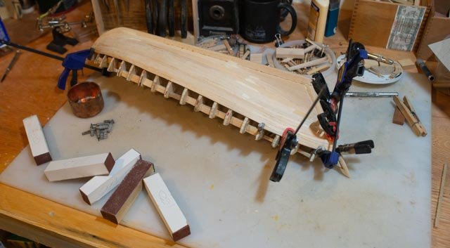
Hi all Christmas is still going on but I am trying to keep going here too. i appreciate all your comments Keith..always a pleasure to have you aboard, your planking remains an inspiration to guys like me....maybe someday I'll catch up Chuck an honor...I will surely be visiting your web store for some line, as this scale really benefits from the array of colors and textures you offer. it will be fun as some will be coiled up I think as the topside will be under construction Joe welcome to you and thanks for sympathy on the struggle to build a shop. Models or home projects do not always mix well. We all keep learning and it is wonderful to start all over. I can not wait till next summer to get rid of the garage door and have a nice glass door to look outside and get rid of the generator. The bigger projects can head for the garage. I also think restricting my shop size for models to a single garage is good discipline. GL this build for me is a great opportunity to study and improve some basic skills. I marvel at the beautiful planking we see on many of these building logs and appreciated learning this easy technique at the conference. FYI the complete version is on the MSW site as a build log. I hope the next and last band leaves me with the ability to have some un painted. I then need to figure how to make it look like cedar. perhaps I will rip down some cedar for the last three strakes????? 51 here i am sneaking in the first strake of third band. 52 these ends are getting tricky. the bow clamp is a reglue to get the plank into the rabbit. happy new year to all
- 69 replies
-
- 5
-
-
- diorama
- Glad Tidings
- (and 2 more)
-
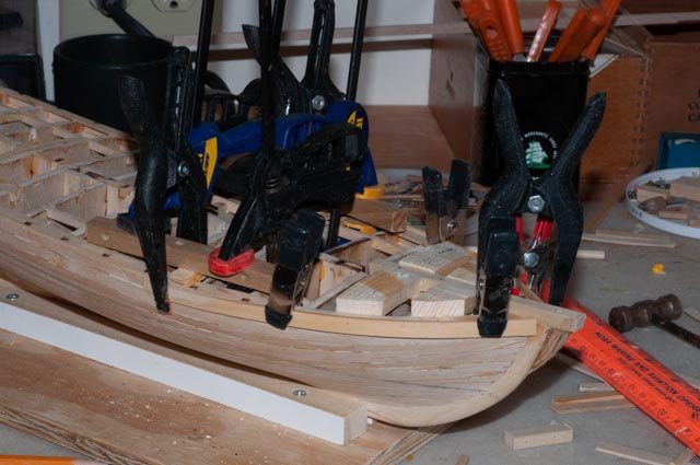
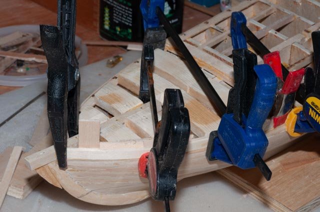
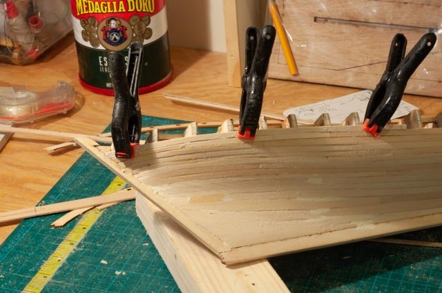
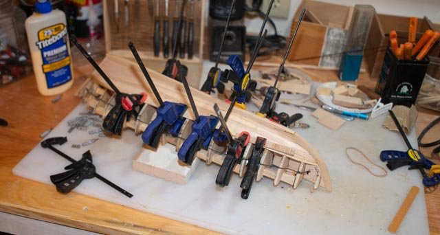
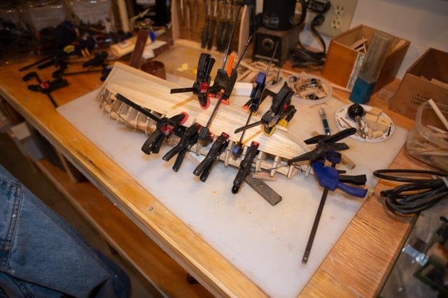
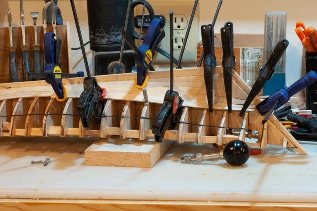
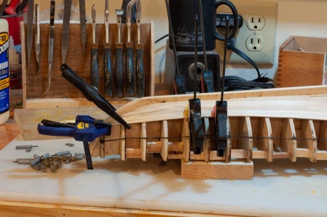
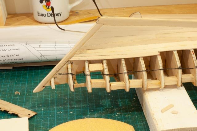
Post 6 planking part 3 complete band 2 I am continuing along in the run up to Christmas with a hope to be able to get the majority of planking on by the end of the year so I can invent the diorama and have a full three months for that part of the first build for the early Pinkies of Boothbay. I find as I work my way down the planks get harder as the process gets more familiar. I keep waiting for the easy piece. 41 we continue to find the need to work out different clamping on each row. 42 here I have added blocking to avoid the damage to the soft bass wood from the clamps 43 this strake is the last one I can get to with the array of clamps 44 here I brought out again the screw in clamps that damage the bulkheads ahead of the game so to speak 45 here we have had to go back to soaking the planks and then to clamp them to dry before gluing up. This strake is the end of band two 46 here is my planned repair for the worse of two sides where I put in the short piece and should have run through the longer piece and after gluing cut the joint. The next time, 4 strakes down I did it right. We need to wait to see how this repair comes out. 47 here we are low in band two and have our most drastic curve. I had to lay it out on ¾ “piece. 48 see it after the band saw cut out. In scale this would have been a 15-inch plank. I don’t know, but I do not imagine this process is an exact replica of the real thing. In my Bowdoin log you can see we went to the local yard where they were installing all new planks on the real Bowdoin. Their step by step measurement was similar but the one hour of steam per inch thickness of plank made the bend both ways. I did not see them wasting so much wood. ….anyway just a thought 49 here we are measuring the last strake in band 2…note it will go four bulkheads 50 here we are with strake 1 in band three, only 2 bulkheads. I am going to try to do this short piece but am ready to abandon if the joint does not stay true Cheers it is Christmas eve and much to do
- 69 replies
-
- 5
-
-
- diorama
- Glad Tidings
- (and 2 more)
-
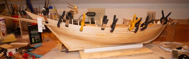
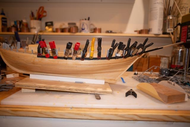
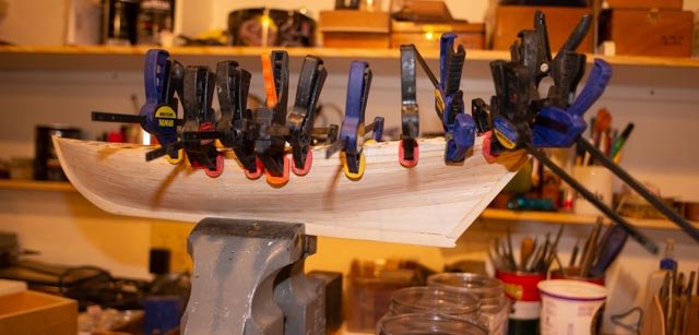
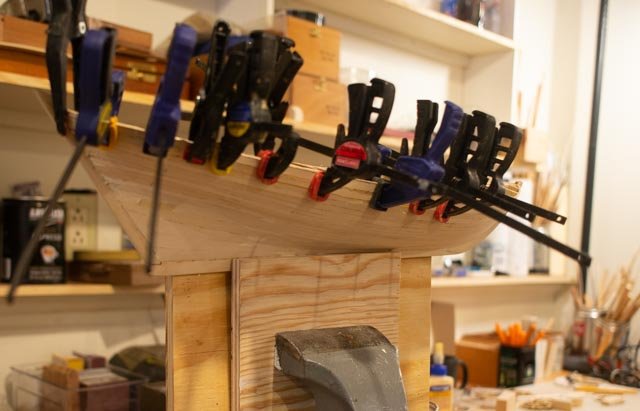
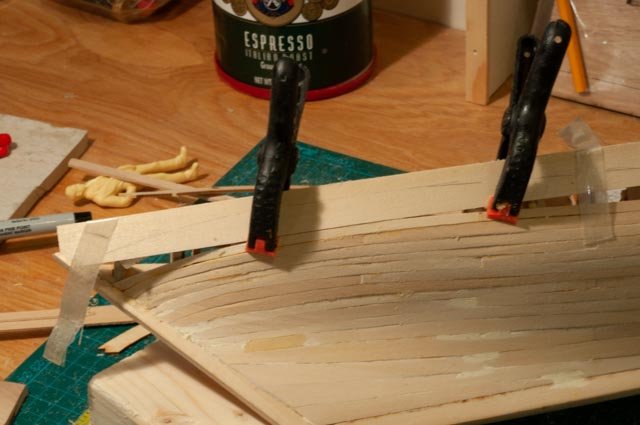
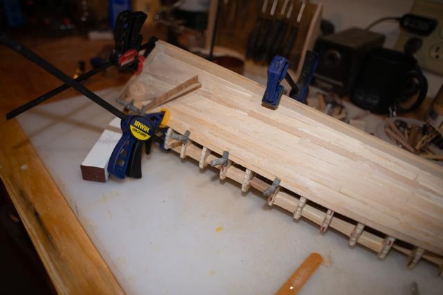
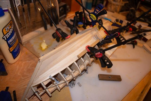
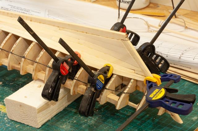
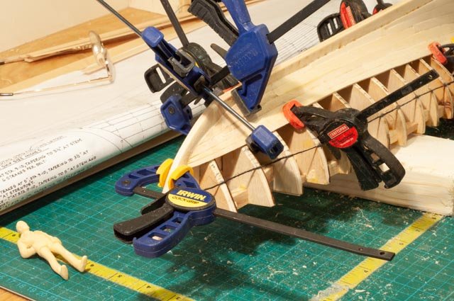
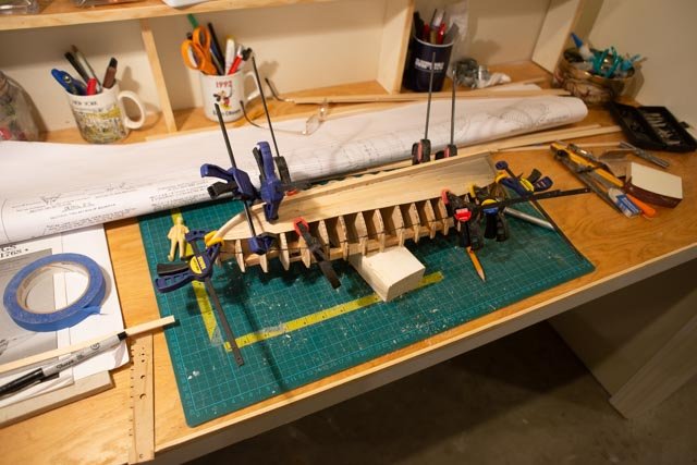
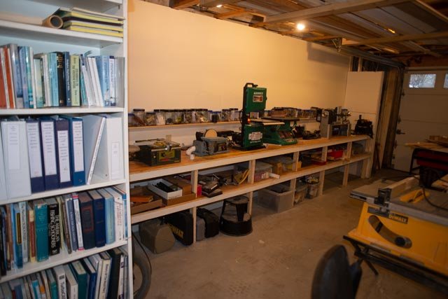
Post 5 planking part 2 Remember the silly goal of 17 days for 17 strakes? Not likely to happen as we are still building a new shop, Christmas is coming etc. We’ll do what we can. Two bands to go with 6 strakes each. 31 completing Band 1 I have decided to keep going down. Others jump up to the top, I think with the preplanning that comes with this method, it makes no difference. Here the clamping is getting harder so why not keep on going. 32 up forward we are having double bends. I tried soaking planks in plane water for a while. They were easier to work but the clamps squished them. Notice the third plank. Since these are so thick, 1/16” I do have the sanding option. Since I want to have some copper on the hull, I think I just found where it is going. This plank also completed the first band of 5 strakes and one steeler. Thanks to the kit design for making that decision, as it does what I needed and helps my schedule that needs to make this a possible 4-5-month build. 33 another oops. I followed the provided layout with the very short piece at the end of strake 5. Lesson learned is to run the plank all the way through in this case and cut in the joint after. I see after a few more strakes the best fix. I am thinking to laminate two pieces over and to feather them out. Alternately I could remove the planks, so the joint is one or two bulkheads away. Also, if I show partial copper, paint and things, I could simply hide this oops. The other purpose of this photo is to record the final measure and fix step. The planks we cut out on the band saw and sanded. Then fine tuning and rechecking of the dimensions. The light pencil line comes from the tick marks on the bulkhead. The piece is next to be sanded true. 34 Here I took the piece we just sanded true on one side, and placed it over on the other side to check it out. It fits yippee….now we trace it on a blank and head for the band saw. Tracing, cutting, sanding rough and in less than five minutes, we are fine tuning it to this second side. this side has a worse defect at the joint of the short piece... a fix is on the way. 35 off to the assembly desk for glue up and clamping. I learned by now the hard way to dry clamp, so all is figured out before glue. 36 here we have a delicate piece and I am proud to have squeezed it onto a ½” blank. Oops our foreman must be sleeping. 37 In several recent discussions many of us complain that power disk sanders and even spindle sanders go too fast. Some slow down but in doing so loose power. One enthusiast in our guild built a hand crank disk and he loves it. I took a 150-grit sanding disk and stuck it to a small rounded piece of plywood with two sides wrapped. The wrap is good for corners and more importantly to give me a good grip. I used this to fair the deck too. The curved block to the right is just that. With 150 grit glued it allows inside edge of planks and certain aspect of other curved sanding. 38 even more fun fitting the clamps. I think I am going to need to start grabbing the bulkheads and hold some small blanks to hold the plans during glue up. 39 here we have two end planks on both sides in glue up. Later today maybe we get the middle one done….then it is almost Christmas tree set up time. Update on the shop build. 40 I got the power tool bench and bookshelf in. I also got my modeling library back up and emptied ten boxes today. Everything is still a mess but working is easier. I lowered this new bench to 34 inches and that works for the tools and is more comfortable than the old set up with three different heights. All for now
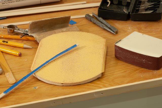
- 69 replies
-
- 6
-
-
- diorama
- Glad Tidings
- (and 2 more)