Jond
-
Posts
877 -
Joined
-
Last visited
Content Type
Profiles
Forums
Gallery
Events
Everything posted by Jond
-
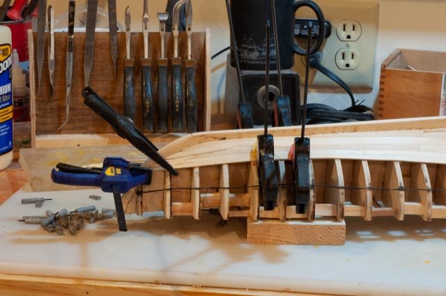
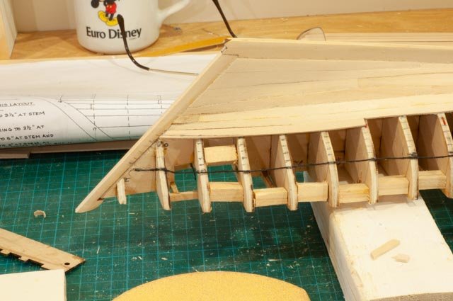
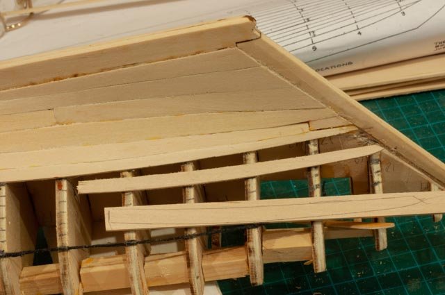
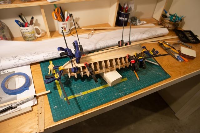
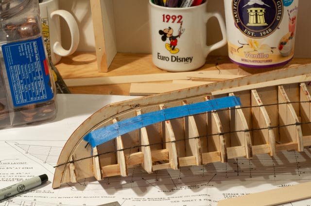
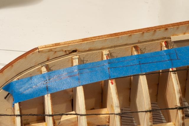
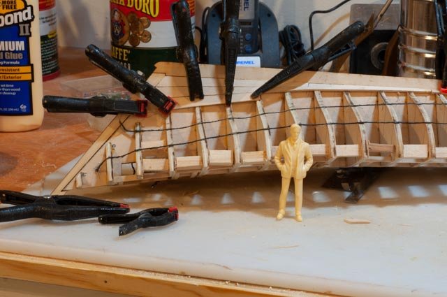
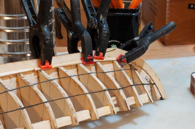
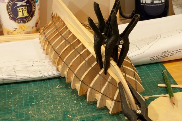
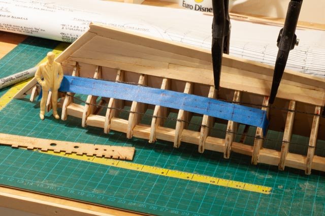
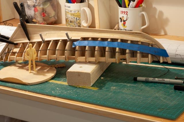
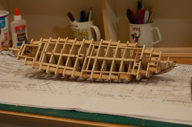
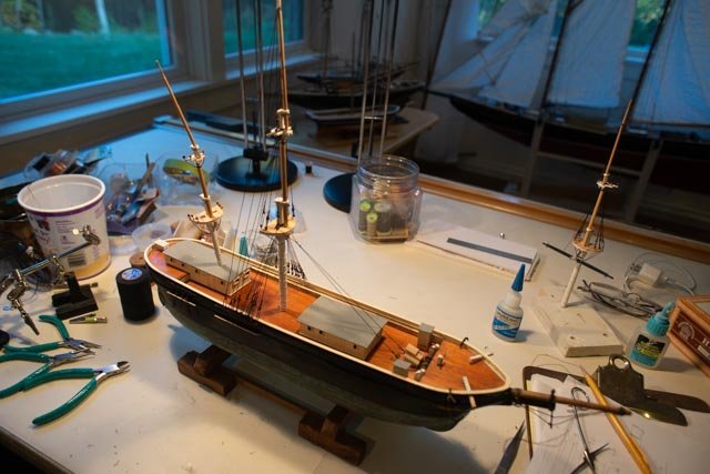
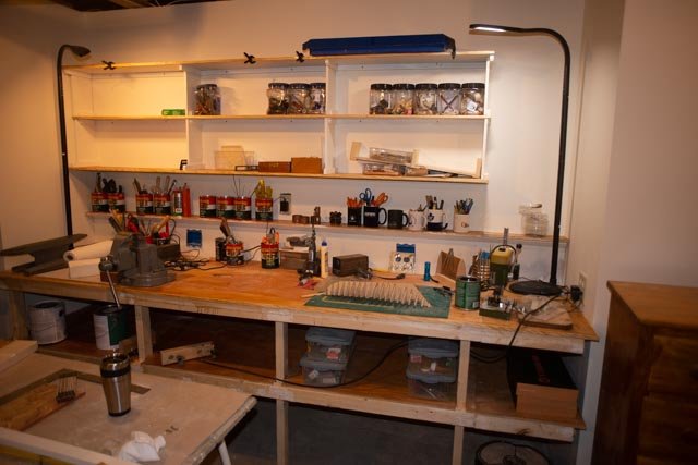
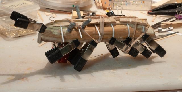
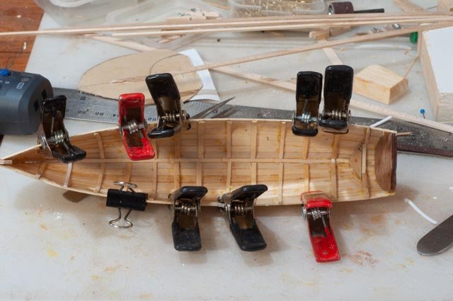
 Post 5 planking part 2 Remember the silly goal of 17 days for 17 strakes? Not likely to happen as we are still building a new shop, Christmas is coming etc. We’ll do what we can. Two bands to go with 6 strakes each. 31 completing Band 1 I have decided to keep going down. Others jump up to the top, I think with the preplanning that comes with this method, it makes no difference. Here the clamping is getting harder so why not keep on going. 32 up forward we are having double bends. I tried soaking planks in plane water for a while. They were easier to work but the clamps squished them. Notice the third plank. Since these are so thick, 1/16” I do have the sanding option. Since I want to have some copper on the hull, I think I just found where it is going. This plank also completed the first band of 5 strakes and one steeler. Thanks to the kit design for making that decision, as it does what I needed and helps my schedule that needs to make this a possible 4-5-month build. 33 another oops. I followed the provided layout with the very short piece at the end of strake 5. Lesson learned is to run the plank all the way through in this case and cut in the joint after. I see after a few more strakes the best fix. I am thinking to laminate two pieces over and to feather them out. Alternately I could remove the planks, so the joint is one or two bulkheads away. Also, if I show partial copper, paint and things, I could simply hide this oops. The other purpose of this photo is to record the final measure and fix step. The planks we cut out on the band saw and sanded. Then fine tuning and rechecking of the dimensions. The light pencil line comes from the tick marks on the bulkhead. The piece is next to be sanded true. 34 Here I took the piece we just sanded true on one side, and placed it over on the other side to check it out. It fits yippee….now we trace it on a blank and head for the band saw. Tracing, cutting, sanding rough and in less than five minutes, we are fine tuning it to this second side. this side has a worse defect at the joint of the short piece... a fix is on the way. 35 off to the assembly desk for glue up and clamping. I learned by now the hard way to dry clamp, so all is figured out before glue. 36 here we have a delicate piece and I am proud to have squeezed it onto a ½” blank. Oops our foreman must be sleeping. 37 In several recent discussions many of us complain that power disk sanders and even spindle sanders go too fast. Some slow down but in doing so loose power. One enthusiast in our guild built a hand crank disk and he loves it. I took a 150-grit sanding disk and stuck it to a small rounded piece of plywood with two sides wrapped. The wrap is good for corners and more importantly to give me a good grip. I used this to fair the deck too. The curved block to the right is just that. With 150 grit glued it allows inside edge of planks and certain aspect of other curved sanding. 38 even more fun fitting the clamps. I think I am going to need to start grabbing the bulkheads and hold some small blanks to hold the plans during glue up. 39 here we have two end planks on both sides in glue up. Later today maybe we get the middle one done….then it is almost Christmas tree set up time. Update on the shop build. 40 I got the power tool bench and bookshelf in. I also got my modeling library back up and emptied ten boxes today. Everything is still a mess but working is easier. I lowered this new bench to 34 inches and that works for the tools and is more comfortable than the old set up with three different heights. All for now
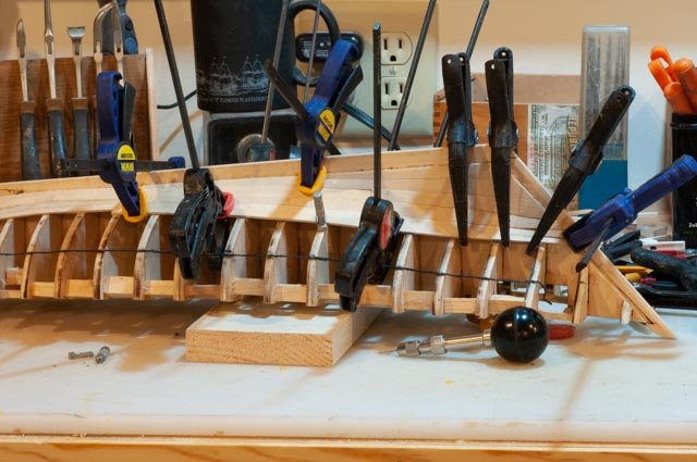
- 69 replies
-
- 6
-

-
- diorama
- Glad Tidings
- (and 2 more)
-
Andrew just caught up with you and love the work you are doing. the deck looks great. I love the rigging solution for small blocks. cheers Jon
-
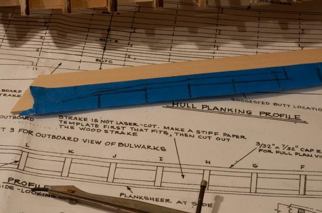
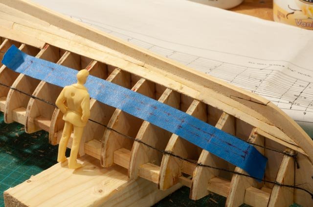
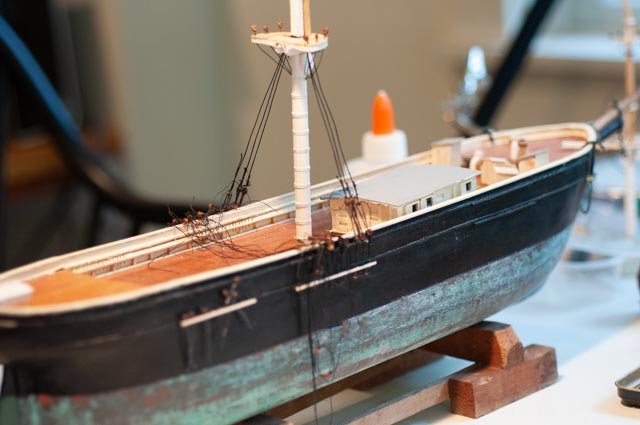
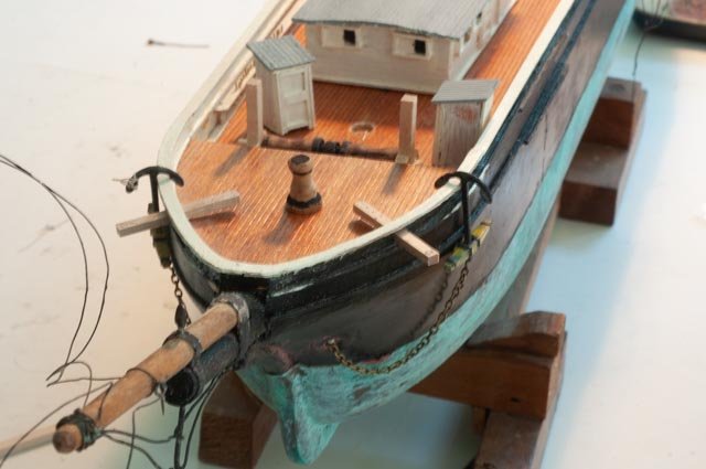
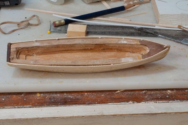
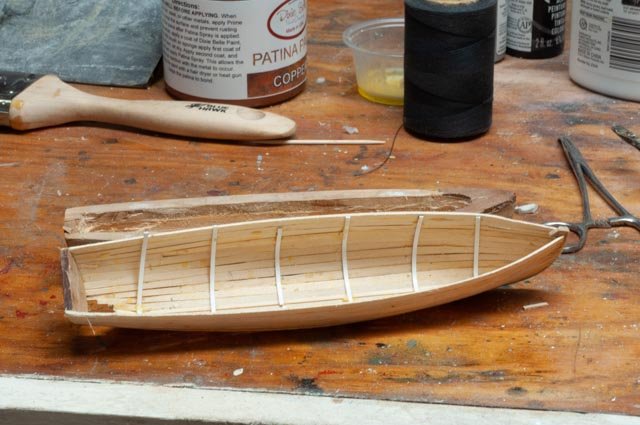
POST 4 Finish the first planking band part 1 I am so excited to have learned this new method of planking, I am logging much of the progress. Probably too much for all you skilled builders. It is a real learning process for me so here we go. Oops and all. 22 Time to complete the first garboard plank. One comment is the instructions from New Bedford was to use a soft pencil compass, so a continuous line can be drawn. I could not do that as my old drafting equipment has hard pencil lead. 23 here you might see I took the compass and placed dots at the bulkheads and mid points and then with a thin sharpie connected the lines. That is the top line. I then took a divider and on this first attempt went to every station, where in this kit, and not normally available, someone has already laid out the planks. I took each point and transferred it to the tape. 24 I simply take the tape and apply it to a blank plank. here i am conservative and use a large blank. 25 when possible I work both ends at the same time. The purpose is to place either two or the three planks that make up a strake on both sides per day. That would mean 17 days to plank this hull. 26 here we are forward adding the last garboard section. these clamps worked on the mid section but not here as the plank twisted 27 clamping is an adventure. Some oops here are coming as the clamps grabbed this soft wood. 28 here our foreman is checking the work on the center third plank. 29 here we think we are doing great. But those two clamps crushed the edge of the planks. My solution was to use an emory board to file the edge smooth 30 here I brought out the screw clamps that some experts advise not to use. There are always a few areas that clamps just cannot get to hold. more on the way Cheers
- 69 replies
-
- 5
-
-
- diorama
- Glad Tidings
- (and 2 more)
-
Great job! It is fun to see her grow so fast before our eyes. I am using this same model to try to depict an original built in 1816. thanks for sharing jon
-
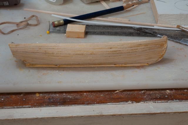
Post 3 the first planks My excitement is that I am working again, not the little progress. Each time I want to do something I have to try to go find the tools. Example: I learned to go to scalpels last year or so. The issue is I have no idea where they are. You can see on the table and old exacto kit. 17 Before planking I chose to complete the under-deck work. I was not too careful with alignment of the stiffening blocks and two of them had to move to get in the cabin supports…oh well that is not all bad. 18 I used a small plywood sheet with a 5" sanding disk glued to have a faring tool for the deck. After cleaning it up, I had several low points. I added in 1/32 strips, and after gluing I resanded the deck. 19 another oops. I love recording oops… I prefer to notch and counter sink the deck support beams instead of cutting each one and gluing it fore and aft of each bulkhead. I must have gotten interrupted because the starboard side aft I cut the slots on the wrong side of my tick mark. Fortunately, I simply added an outer beam, and all is well. 20 pop the cork we have our fist plank in place. No whiskey until the last one. 21 that first one went OK on both sides, so here we go with number two. I found i need to leave a little extra when cutting as there was trimming needed to get them aligned. i look forward to using the technique learned in New Bedford after completing the straight bottomed garboard Cheers
- 69 replies
-
- 5
-
-
- diorama
- Glad Tidings
- (and 2 more)
-
Keith happy to hear from you here. I love to drop in and see your work too.. as soon as i get the 1st Pinky [ Superb ] planked I will be back here rigging away, since that Pinky will be on the hard with a crew trying to rig it too. I will need more figures to do that. cheers
-
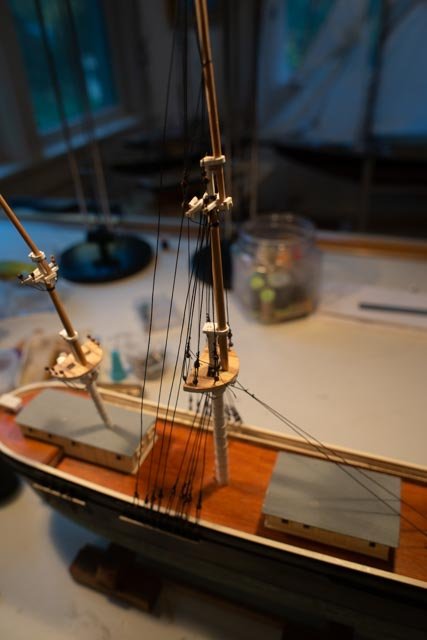
post 16 a new shop and sitting on the side for a awhile In another build of 1st Pinky Schoonerin Boothbay I share both eh house move and deadline for that build. As we are heading toward the end of the year I want to update what we are doing on this build. Call the ship build vs the schooner build. Ap 100 I decided to completely build the main mast in place. So here I started with the forestays. Ap 101 Here I went ahead and put on several of the top shrouds. I learned a few tricks while in new Bedford to help speed up ratlines and I look forward to trying it here. Ap 102 here is the siding story. As recorded in my other log, I have moved and am in the process of building a new shop. Aphrodite had a nice car ride and is now happily resting on the shelf of the new rigging desk. Once we get through the holiday rush and the shop is mostly up and running, she will get some more action. I also have a new side mission as a version of Cutty Sark just showed up and I need to do a bowsprit repairs. I will share that here this winter too Cheers
-
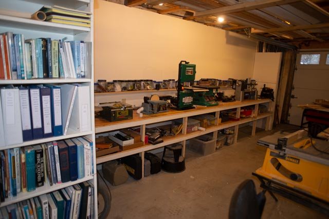
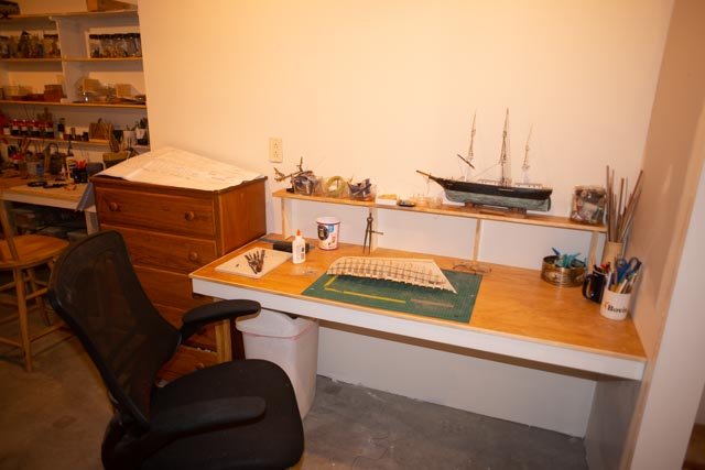
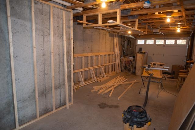
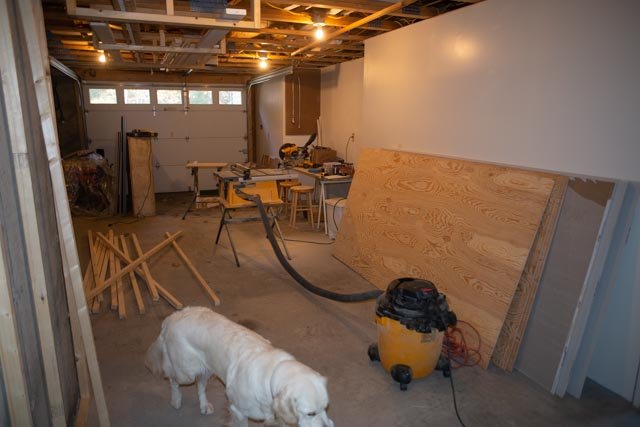
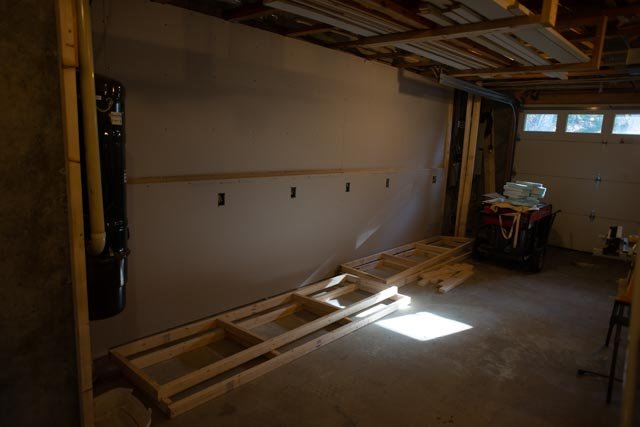
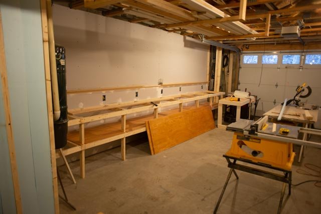
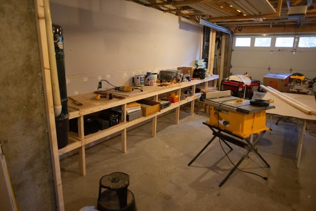
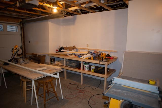
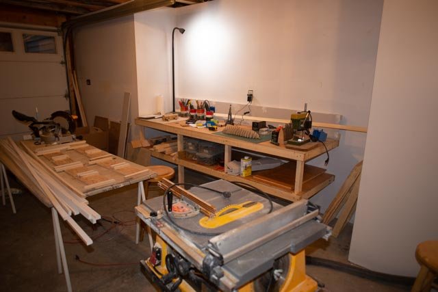
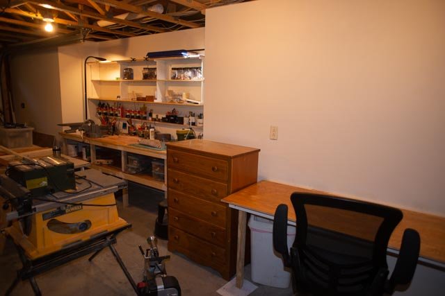
Post 2 second start in new shop. The impact of building a new shop is overwhelming to one’s schedule. I spent the month of November trying to get enough done so that by now, early December, I could begin to focus more time on this build or perhaps these builds. These old bones don’t get as much done as they used to. And I am sure the drywall sheets of today are much heavier than they were just a few years ago. The next ten photos are to record this month building the shop in the early stages. O4 this is the starting point. The home we bought is built into a hill overlooking an active water way. The inner half of the lower level is all basement carved into a ledge. One end has a garage door that I hope next summer to change into a glass door. The first job is to skin the concrete with insulation and drywall. That also gives us the back supports for both benches and shelves. and lets the heating system work a little less. 05 the water side is a finished wall running the length of the house. Guest rooms and family room are on the other side, so dust and smells will be under approval of the rear admiral, I fear. I plan to do fiberglass and any other stinky stuff in the garage, which is fortunately heated. A shop dog is great part of the arrangement. 06 the lower wall is out a few inches to allow electrical work and a long shelf. The bench frames are simply screwed to the wall framing. 07 call me old school I just love varnished pine for the benches. You can see the insulation on the walls that continue north of the shop and will form a long hallway and gallery. The black can that’s hanging on the wall is a whole house vacuum. I am thinking of maybe using it for dust control but need to study it. 08 the bench is in and will fill up with all the power tools on the inland side. 09 the water side has jogs and will allow a bench nearly 10 feet long. This is where most of the work will get done. 10 and here is the restart of the first schooner. The upper shelve framing is on the layout table so one can see the splitting of time will continue for some time. 11 finally we have the planning and rigging desk. Here one has a comfortable chair, needed to tying all those knots. The old bureau holds clamps and all kinds of things. 12 the first shelves are now up and I am finding a need to get things out of boxes even if this is temporary. 13 here we are finally getting to work on Superb. I have been working on the rabbiting and am now ready to get the keel stem etc.. in place. Each time I start something I have a panic to try to find a tool, glue or something that is hidden away in a box. 14 Having just been to the New Bedford conference and enjoying all the experts, one thing of focus was how to do better planking. A recommendation I took away, and am using here, is to glue dark thread to identify the planking bands. It was fun to do, I have never done it before, so I am optimistic looking forward. 15 finally we can get out the plans, sort through some materials and think Also, as a note the ship model on the shelf is one of my builds [ Aphrodite] that is still active and will get going but does not have the deadline of next summer showing. I will continue to post there as and when I can get to it. 16 in this detail shot the red marks are the layout of butt joints, the pencil ticks for the lower band of planks and rabbit grove looks deep enough for the first time[ we are still learning]. I am going to use this model as a learning tools to improve my hull planking. So this concludes a month of work. Not much schooner progress and heading into the holidays we all know what that means for the next month. I hope to plod along and make progress. Cheers
- 69 replies
-
- 5
-
-
- diorama
- Glad Tidings
- (and 2 more)
-
Dear Highlander welcome aboard . Maine nautical history, especially centering on ten mid coast are where I live, adds much joy to the builds I am trying to do. regards
-
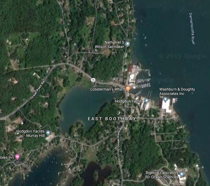
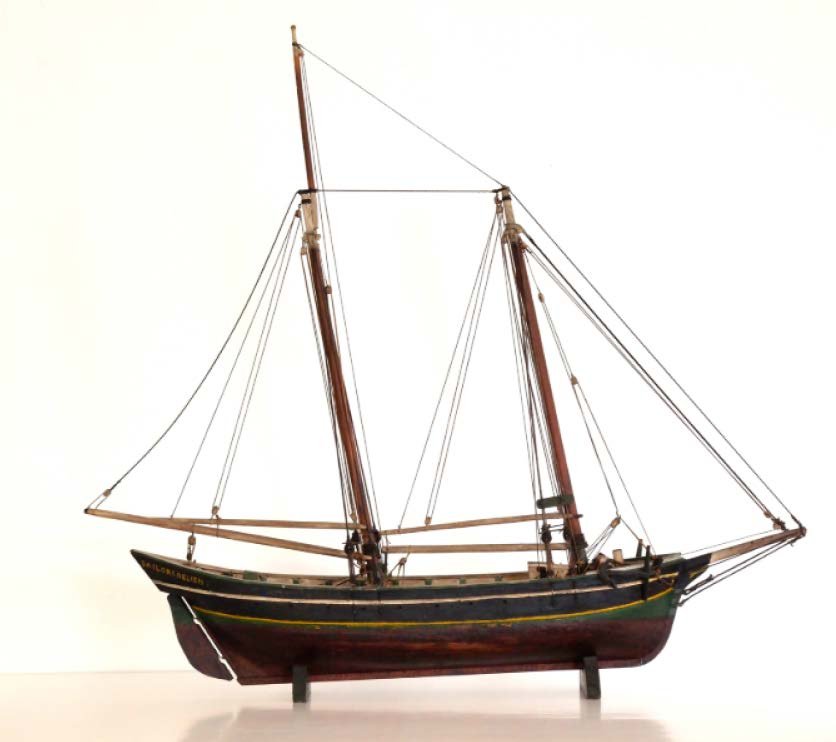
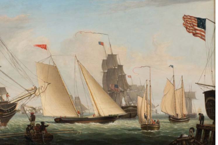
Post 1 early November, the process begins Superb log a 1:24 kit bash This project is intended to celebrate the building of the first Schooner by the Hodgdon family, now in its fifth generation of ship building on the Boothbay Peninsula. There are several firsts that could have been chosen as the builder started in 1816 and then migrated east across the peninsula and then south to the East Boothbay Mill area over these first ten years. Before we make any decisions, we must first thank and give credit to Barbara Rumsey who tirelessly researched, and fortunately for us published her work tracing this history around Boothbay. In the Book Hodgdon Shipbuilding and Mills, A documentary History of the first hundred years, 1816-1916, published in 1995, Barbara tells us the story. To help with this upcoming exhibit, my first thought is to build a diorama depicting the final stages of building this schooner in the late spring of 1816. To do this work I have expanded research into re reading sections from some favorite authors. There are no surviving half hulls and many of the Hodgdon firm’s records were burned in a fire many years ago. I felt that it would be safe to take the plans created by Howard Chapelle. Even better I found that there is a recent kit using Howard’s design for the 1939 version of the pinky that was built and he apparently sailed before WWII. As I begin this project, I am in the process of moving to a new home and needing to rebuild a shop from scratch. That means lots of good news in the opportunity to improve the working environment. but an obvious crunch in time for me to have this done by next May. I bought the Glad Tidings kit with its great set of his plans. At the 1:24 scale it represents 39 feet long deck and 40 +/- top of rails and if I go back to the peak of the stern I can get to 42ft.?. This is one of those rationalization conversations. The first decision is what convention to use for hull length. I will quickly take a leap of faith that these history books and lists use the length of deck from inside the taff rail to the forward most point of deck. That was pretty well confirmed in the schooner books I read while researching earlier builds. But what records did they keep confirming what they meant for the tax records, used in Ms. Rumsey’s research, to determine lengths of vessels. If I want 42 feet, I have some choices: Do I build it as is? If I am wrong, it is only a few percent…so it should be ok. But then a diorama with a schooner roughly 29 inches long including all rigging is tough to do. On the other hand, I do not have time to recreate too much. This is not a build to go to frames unless I want to show something under construction. Do I scan the mold plans and adjust the scale to replicate a 42-foot schooner? I could drop to 3/8 scale = 16 inches +/- on deck or even ¼ scale = 10 inches deck to roughly 15 inches +/- overall which I think in the end is easier to do in a diorama if I want to show the launch. · The second decision is …am I building the first schooner built in Boothbay or by the first builder of Boothbay. Superb was not built in Boothbay but next door by a Boothbay builder… the first schooner he built in Boothbay was Ruby in 1823 maybe or Betsy 1824 surely. Both were pinky shaped and of similar size. So, we have the boat, we just need to settle on the name and town. Diorama option 1: build at 1:24 To build the kit hull through the deck. Then to show construction activities around the schooner. Perhaps rigging a mast and or the rudder. This would use up the kit material and get to a timely delivery. The problem is with the large size there will be little room to have things around. Think of the huge figures etc. Diorama option 2: build the above in 1:48 There are other considerations. If I simply use the plans for this build, what do I do with the kit. I find that Hodgdon built a 59-footer just 13 years later after they had arrived in east Boothbay. The largest Pinkies were built around 1831 at 69 feet. I would say looking at the list however that was an odd ball and not the norm. Also one does not just up the scale, one needs to research what was stretched to add 20-25 feet to a 40 foot schooner. After that large build, the “pinky’ classification stayed around the 39-42-foot version. That all makes sense to me because Howard Chapelle was a lot smarted than me, and he chose this size for his developed plan. Even so to build bigger would extend middle sections of the hull in some way that cannot be my design, so do I use kit parts for my material inventory and trash the molds or go ahead with one at 1:24. Diorama Option 3 only use the plans and raw material. I am considering to build at 1:48 or 1:64 Superb was believed to have been built on Westport Island. That is about three miles west of us. At the time it was part of the town of Edgecomb, which is the northern third of the Boothbay peninsula. Since after the move to East Boothbay in about 1823, the Hodgdon boat works remained there until today. 01 Here we have a modern google image of the east Boothbay harbor with the active Hodgdon boat works. This property was purchased much later than the period we are discussing. It was infact sold again last year to Washburn and Doughty. In the 19th century the Hodgdon boat works included all the land where the marina is now located. That was sold in 1970. Not long after that ventrue it became ocean Point Marina. The adjacent ship builders park is the once owned by the Reeds but changed hands a few times. The famous Adams yard where two four masted schooners were built in 1893 and 1890. was located where today Washburn and Doughty builds large sea going tugs and fire boats for offshore oil rigs. Caleb Hodgdon both the builder of Superb and its owner relocated to start the Hodgdon Mills in what is East Boothbay today. He also maintained ownership of the 42-foot Superb for many years. So perhaps I scale down and scratch build a 1:48 or 1:64 inch water line model resting on a mooring to be Superb and then a partially framed hull in the yard being build and I change the year to 1824 and call it Betsey or Ruby that were built there. I would use the rigging on the moored vessel and have the deck and a few things completed on the model. I might just bread and butter water line up the build up everything I am not building on the new one. If the new one is under construction, I can have incomplete planking and not worry about copper and all the other niceties that I see in the painting I have been studying done by Lane As to the look, I am going to depend on artists views of the mid 19th century and not the new reconstructions of brightly colored Pinkies that sail today. 02 Here we see one of many internet photos of models and that closely follow the paintings on coloring. 03 Here is an internet image of the proper coloring of the era. I say that because there are several contemporary paintings by lane also posted that clearly show the conservative coloring [black] with the copper bottoms and dark green under the wales. It is interesting to see all the bright colors of the later versions. Action for November I am entering a month of moving from one house to another and building a shop. I need to put together the frame from the kit and get going. No mater what option this build ends up with, the kit needs to be built up through the hull basically as intended, so here we go. RC follow up options. This is my overall plan to have scaled details static models at sensible scale and the simple built up RC versions. No more Bluenoses too detailed to sail at 7 feet long Since I may also build a 1:12 radio sail pinky after this diorama, I even suggest three possible builds all on one log. 1 build out the kit to have something to show next spring likely to be built through the deck and men working above deck 2 build the diorama at 1:48 or 1:64 with two boats. With enough time I could draw the fill in frames and have some areas without deck and planking as a better view of the building of a schooner. 3 build the rc. At 1:12 I plan a similar rebuild of Bowdoin as RC but that is another story. Much to think about I think time will be the ultimate factor in this decision. I have no tools now, so thinking and sketching is what I have. This writing as usual helps, me focus and draw conclusions. The plans are even packed in a box, and I have no idea in which one, so I have nothing to scan to play with in cad. I have no idea if this is a kit bash or a scratch diorama within which I use some of the kit. I am not building Glad Tidings as advertised, but will surely give them credit. I spoke about this posting question to colleagues at the New Bedford NRG Conference, and they agreed it is sometimes perplexing but not too important. My conclusion is I am kit bashing of Superb into a diorama as per option 1......we'll see Cheers
- 69 replies
-
- 6
-
-
- diorama
- Glad Tidings
- (and 2 more)
-
Pete In my beginning stages of learning to build scaled sailing models, I read somewhere that the rigging needs to be down sized roughly 3/4. considering the difficulty of managing sails, that are not self tacking, this is partially solved by leaving off some of the sails. for the keel I prefer the added keel for two reasons. typically one needs 10-15 pounds of weight and also with a 50 plus inch boat needs the depth of 18 inches. that means adding some embeded bolts but being able to display the hull out of water in a realistic way. similarly I add to the rudder a removable piece, because at scale the rudder will not work well. the size for me is to double it. I sailed boats in the 50 inch size and they work well. they have relationships that are easy to find in the class specifications. I would suggest AMYA website and the US vintage website for the serious racing folks. Through those sites one can find a class of boat in a similar size and see the area of sails vs length of boat etc. I would then reduce sail, not shorten mast and boom. in my Boothbay Harbor One Design build log I shortened the jib for self tacking and then main to balance the jib. I fully intended to sail Bluenose but once I got into the detail, I feared seeing here go blub blub and she has stayed dry. my next venture is a double build of a schooner so I can have fun with detail on one at a smaller scale and build the sailing version more simply. sorry she is scrapped. maybe someday another go best if luck
-
I logged on to catch up and continue to enjoy your progress. you make the ratlines seem effortless. Now with the fore and aft stays she really looks great. thanks for sharing jon
- 356 replies
-
- 2
-
-
- red jacket
- finished
- (and 1 more)
-
ps on above simple masking tape on the outside of the molded frames and using drilled toothpicks with glue through planking into the molds allows separation in the removal of the molds.
-
Pete I just found you again as I wanted to see how you have done. I have been away from modeling about two months as I have moved to a new house and am in the rebuilding of the shop. Considering your recent "stop work order", I want to say a few things about my bluenose build 1:24 if you run through the first few pages of my log you can see that the frame stage, where you are now, was hung on the ceiling for roughly ten years[ 2002 to 2012 before I picked it up and did the hull. then it was a few more years before I continued topside. These pauses where due to work mostly, but the time between phases also gave me time to sort things out and by working on other projects be more prepared to continue. one thing you might consider when you pick her up again is to use the bulkhead frame as molds as I did and as I was taught at the Wooden Boat School [ same as the magazine in Brooklin Maine]. in my early pages you can see all the drilled holes in the plywood bulkheads to promote the Dremel saw to cut them out of the complete and fiberglass reinforced hull. then one adds light deck beams and very light deck and top side structures. the plywood keels section would also be cut down to maybe one inch inboard of the hull to remove more weight. the coat of fiberglass over the light planking makers he rock solid and removing all the molding makes her light. as you do it you add cross beams for the deck. the deepest screws that go in sideways to the keel /keelson should be removed and only glue any where you can not get to them from above after planking no mater what you do, the frame at the current stage is great nautical ceiling art so please keep her around for a while. best of luck on whatever you decide jon
-
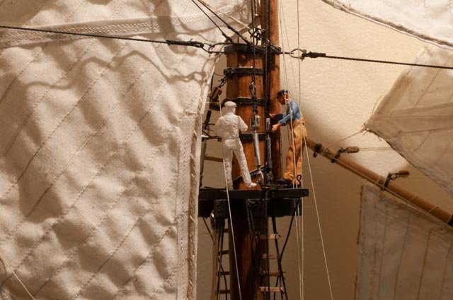
Post 15 Wow two months and little to report. I wanted to share that I am in the middle of a major change. I was fooling around in late august and ended up buying a new home. Too many reasons and not for here except the following. The new home is smaller, I think they call it downsizing. The good news is there is a large basement area that is wide open with a current garage door that I can change to a glass wall for daylight. I get to build a whole new model shop. Wow. I will include a few progress notes on that as I go through it over the next winter, since this is the model that will last through the whole period. One point to be sure, since that basement is part of the lower level of this new home and includes guest rooms and the family room, sawdust and smells will be separated. I will have a third stall in a heated garage where Mr. Table saw and all the larger scale work will be relegated. If I get clever that will be seasonal. The progress on Aphrodite has been slow because of all the other activities. There is also some amusement that anyone who has done this before will appreciate. Because my current home just went on the market, the shop has been basically packed up and boxed. As soon as I move out in a few more weeks I can complete clean up and painting of the old stripped shop to make it shiny for the next hobbyist. In that process I naturally packed too much. I had kept out what I thought I needed to keep working on trimming the masts. Alas, I ran out of thread for the shrouds and the book that confirmed where to tie a few things off. I had to search and find them and now have two open boxes to deal with. Of course, I could had ordered more thread, but I was successful in finding enough to keep going Progress through the end of summer I have read through many logs during the spring and summer. They were for far more sophisticated builds like clipperships, but wow there’s so much to learn, and they are the best way for me. One issue to decide is how much prework to do on a mast before stepping it. I would say more of the recent logs I have scanned say…. do everything you can possibly do before you mount a mast. Being a student, I decided to try both ways. I will build the foremast and mizzen off the ship and build the main mast in place. I learned on my big builds that work off the schooner or ship would be a must. I felt though that this ship is so small that I can almost rest my elbows on the table and thread dead eyes. We’ll see what happens. I think it will be ratlines that kill me in place Ap97 here we see the main mast set and the first shrouds going into place. As I understand it this is done in place in either method it is the upper masts. I chose this to build in place following the premise of starting on the inside and work outwards. Ap98 here is the first completed [ not painted] yard arm and upper shrouds on the foremast. The yard arm was a real treat as I followed Crothers book as best as I could. i left all the lashings loose so when I feel the major movements are over I can tighten them up and tie them off. This new small scale is tough for me and I know this will be student's product, so be please be kind about my learning to cut off stings closer to the knots and getting my ratlines straight Ap99here for fun I temporarily set the foremast in place just to take a look. I will do one more update for this old shop and then we need to get all new benches etc. before we are ready to do more. I also have a commitment to make a schooner over the winter, so I know it is a while before Aphrodite gets close to done. I also look forward to going to the October conference in New Bedford, Ma cheers
-
great news I found your log and will follow along. I need time to finish my sails good luck
-
Damian fantastic news. Later in the next winter I hope to get more work done on the Bluenose sails upgrades. for now I am in two other projects. I will look for your log cheers
-
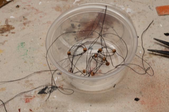
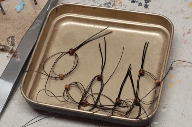
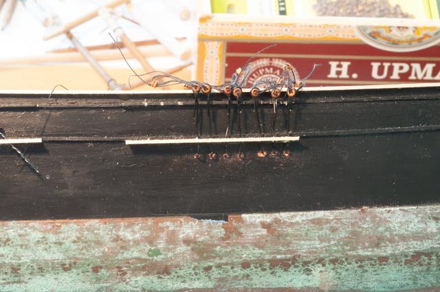
Post 14 summer update Summer is on, and many things slow down our modeling process. A new sail boat, researching newer sails, regattas, and we all know the interference of yard work. I wanted to make at least one posting in July since a few discoveries are underway. I am sharing here some real trial and error events. This is the stage, I can say that after reading so many other logs, that I am supposed to finish the deck furnishings and make up the masts. All the time, we are preparing for the first lower mast step and shroud work. I have made a few steps, so let’s write them down. Ap87 this is an experiment for me. It is the first work I have done at this small scale. I tried using 26 gauge wire and twisting it. I see many others do this for eye bolts and the like. I don’t like the resulting look Ap-88 here I go up to 24-gauge wire and squeeze it around the 2.5 mil dead eye. I like the look and will go with it. Ap-89 The next challenge is to figure at what point do I sting the deadeyes. The issue is threading three holes through a 1/16” diameter dead eye requires holding the dead eye with something [ I used a tweezers], and after glue tipping the thread forcing it through. I do not see how I will ever do that if the deadeye is sitting with its back close to the hull…….we will come back to this issue Ap 90 time to set up for the topmast tops and the top gallant masts. The tops are delicate after trying some store-bought metal tops, but I have to drill 4 eye bolts into them. I find using the bendable styrene the easiest solution for me. I had bought several different sizes so I can experiment. Ap 91 here the styrene is in place and I drilled the holes through it for the eye bolts that go in next. Ap 92 here we are turning the windlass. It is fun to work on these parts. I am taking all the dimensions and details out of Crowther’s book. Ap 93 now back to the dilemma [ for me anyway] to thread the little dead eyes. This is my trial and error approach. I have selected the main lower mast to set first as it is in the middle. I am pre threading dead eyes in batches of 6. That number has to do with attention span. Ap 94 next I pre-fit chain plates and the lower hoop simulated with 24-gauge wire. Several of these ended up short so the next batches will be a little longer on one side. Ap-95 I have set 7 so far. I drilled little holes and bent the bottom into the hull. This will make them more stable when I start teasing the lashing to make them the right length. We’ll see if this method works. My logic is to work through 6 at a time of each step. After I have one mast ready, I will start splicing in one end of the wrapped shrouds and setting the height of the upper dead eye. there are other issues there too, so we shall see how this goes. Ap 96 here I have put a few of the on deck items in place. The windless will be tight to fit in as we recall the original main deck is just a 1/16 too high. Many more things going on, so the next update is likely in a month Cheers
-
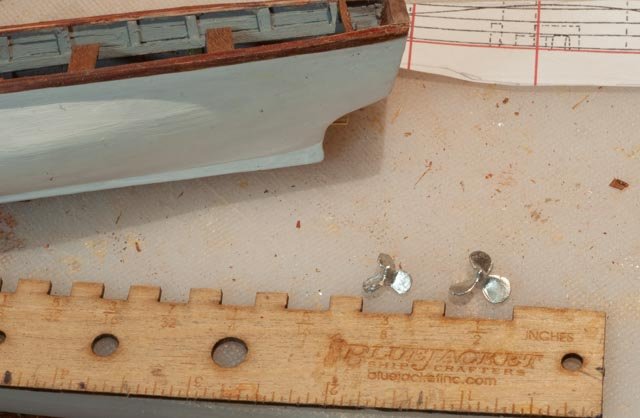
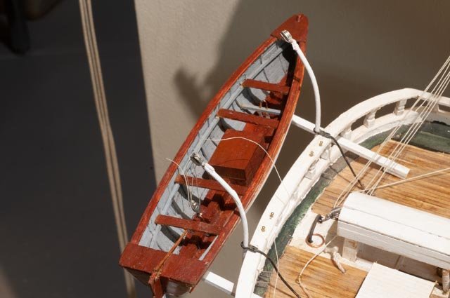
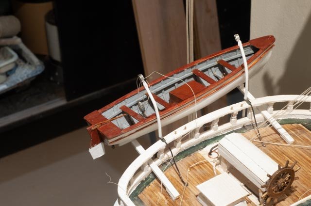
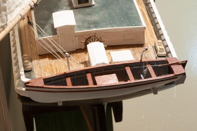
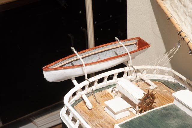
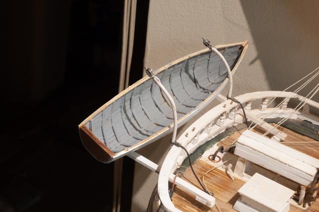
Complete the yawl boat Sometimes we have to say enough and stop working on something. Today that was the yawl boat. 23 I went back to my friends at Bluejacket and bought a bunch of stuff. Most was to build up supplies for the Aphrodite ship, but I got a few of their smallest propellers. Here I have ground it down to fit on the yawl boat. 24 here is the stopping point. I need to transport the schooner to a few sites this summer and there is no way to keep the yawl boat in place. Moving the schooner, the other day I broke off the strong backs. Yesterday I needed to remove a davit and broke it. Today I started rigging the blocks but if I do, I cannot remove the yawl boat. You can see the block engine cover and boxed shaft cover. I made up yokes and the little copper wire to hook the blocks to. 25 here we see where the davit lines and hull lashing will eventually be made off the taft rail pins. 26 here it seems obvious that the block and tackle make a difference, so I will rig them and have them at least in place. Lashing will wait till we are back home. 27 here we have the overview of the after deck and I feel this is better to have than the silly block and fake canvas i used last year. 28 I end with the view showing her sail away. It reminds me that I don’t have the name on the transom yet. We never really finish do we Cheers
-
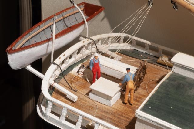
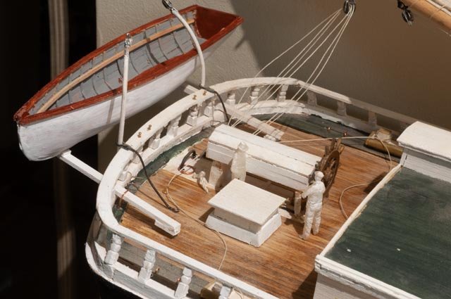
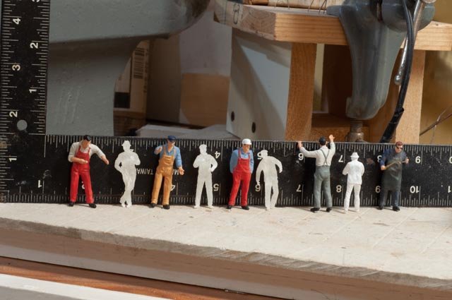
People sizing post A little more progress has been made on the yawl boat and a need to settle on figures, that is size of figures. I also need to give credit for the drawing in the last posting. The yawl boat design comes from the book Anatomy of the Bertha Downs. A great book for scratch schooner building. 16 when I was restoring my 78 year old real BHOD sailboat in 2015, I learned a trick of boat builders to match up the different mahogany wood colors. Mahogany bought in 1941[ likely from the Philippines for the combing is not necessarily the same as the piece I bought from Honduras [ via Rocklers] for new work. Intelux makes an “ Interstain” that brings out a rich color so we all look closer together. This can has been parked in my shop slowing drying out for nearly 5 years. I am Using cue tips to go to the scrap left over blocks form some old kit for the transom, to ripped planks from planks bought a few years ago for the model of my BHOD sailboat. 17 here we see a richness added to the planks that should help when the different mahogany blocks are added for the engine house Now to the figures. 18 Here we see two of my five-man crew that are used all through this build. I bought them online as O gauge railroad workers to be the same scale…1:48. Well funny story if you google O gauge it says they are 1:48……well hold that thought.... also these guys could row that yawl boat. 19 My son put me onto Shapeways the 3d printing folks to get crew for my 1:24 scale Bluenose. I went back to buy 1:48 figures from them to use in the Bowdoin Diorama. They are noticeably smaller than these O gauge guys, so I thought they may have shipped the wrong size. When I measured them, sure enough they were right on; standing up straight they get to 1.5 inches. 20 let’s line them up and see what we get. The O gauge guys are all 7 feet tall!!!! So check it out if you are using o gauge figures. Mine are all roughly 1.75 tall. I have been using them for years and oops many false images…oh well live and learn. 21 up in the rigging it looks like father and son 22 these properly sized figures change the whole concept of the yawl boats size. Fyi the seat clamp is maple…my first hard wood milled from scratch. Cheers
-
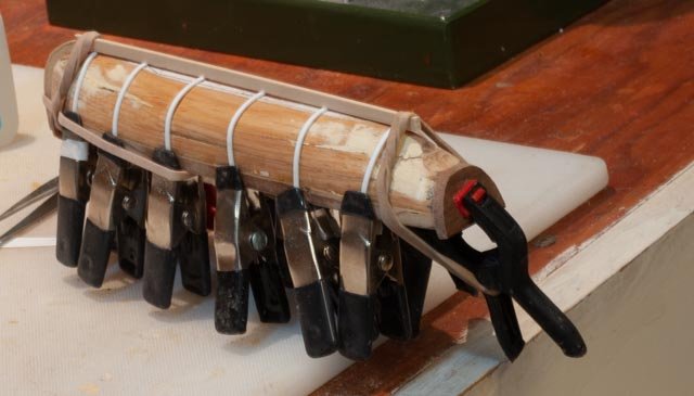
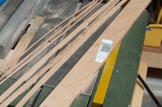
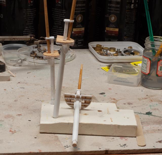
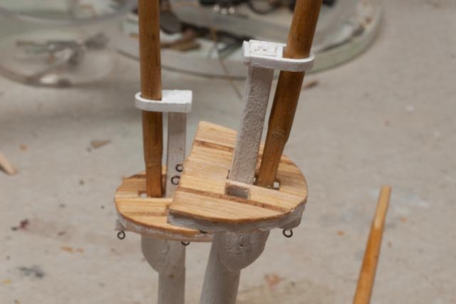
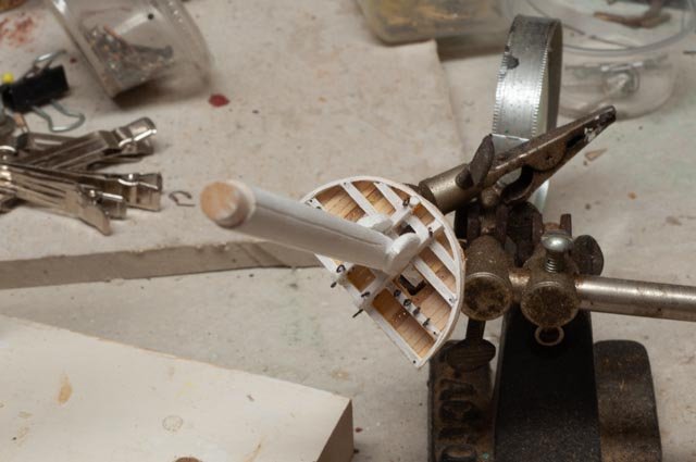
Post .................rebuild a yawl boat Ok I thought it is about time to record what has been going on as I only have a month to finish and give a few talks. I have been dividing my time between completing the Bowdoin diorama and getting it to the store museum....done. Fixing two schooners Bluenose and Herman Zwicker for the store....done. Aphrodite the first ship built here in Boothbay....mostly research and night reading of blogs with a little mast work on the side, and here. So far, the ratlines are sort of done. Cn19 5 I need to tie off the sides every 5th slat going up and the third tie offs for the center shroud on the fore mast. the yawl boat Up through the radio sailing effort on the original build, I made a plug with a fake canvas cover acting as the yawl boat. I have never seen a photo of a cover on a yawl boat, so now that Charlie is retired from sailing and supposed to focus on more detail, I have no excuse not to have a real yawl boat. A colleague at the local Downeast Shipmodeler’s Guild showed us one day a plug for a small Whitehall where he had routed out the interior of the plug so he could use normal clamps on the bent frames and then the freeboard portion of the planking. He also used hard wood for the frames and steam to bend them and maple planking… wow. that was a brainstorm for me. Cn19 6 here I tried taking some hard wood and steaming it in a can. really a failure and everything snapped. After three unsuccessful attempts to bend frame that tight using hardwood and boiling and such, I needed a solution to get going. Many great builders talk about how easy it is to bend maple and other hard woods. I am not there yet but am determined to get their soon. let’s follow my learner’s approach 7 first off what plans. There are a few to choose from and this one matches up with many of the photos. I put it into turbo cad and scaled it. I plotted the offsets for each 1\4 inch, then traced and mirrored lines so i could cut out 4 small sheets of plywood 8 here we see I made the plug using build up plywood so I could use the jig saw to cut the interior. It's covered with floor wax and I am using styrene strips that I will remove later for setting the planks away for the plug and be able to remove it. I will figure out how to bend the ribs in after I remove the plug. the transom is mahogany and the keel and stem for the last time in my career are bass wood. 9 here I remain the amateur using basswood for planking. During this process I was milling my first ever pear for the fairlead planks on the mast tops of Aphrodite. Wow so different. I also milled down some maple and will use it in the finishing. I think I might put a thickness sander on my Santa list. I know I need mahogany for the engine house, gunnels, seats and transom, so maybe this is a transition for me. This hull is painted and smooth outside and painted gray inside, so I am still with basswood. 10 here is the top plank. Looks like putty again but my spilling worked out better than before. Maybe three of four more boats and some better wood and I’ll get it . 11 this top view shows the challenge to get the plug out. There was some convincing and scalpel work, but nothing broke 12 hurray we are separated 13 here we see the inside after separation. the styrene ribs come out and wood goes in. 14and here we have ribs in. and yes, I used ammonia water and bass wood and they are not perfect. I have a few larger frames as they hold the motor box. That was a guess on my part. It is the problem of being a retired engineer. There will be a floor covering the bottom too. The dot on the triangle was a bad attempt to layout the hole foe the shaft. When drilled for the outside it was a bit lower. 15 here we are with gray prime coat all over. I just wanted to see if we fit. Now it's time to start building the interior and cleaning up the exterior hull. Cheers

-
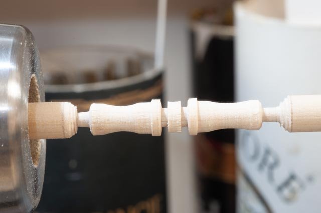
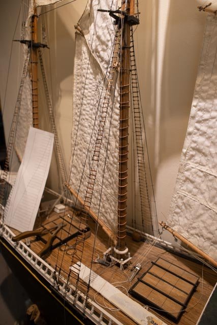
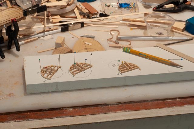
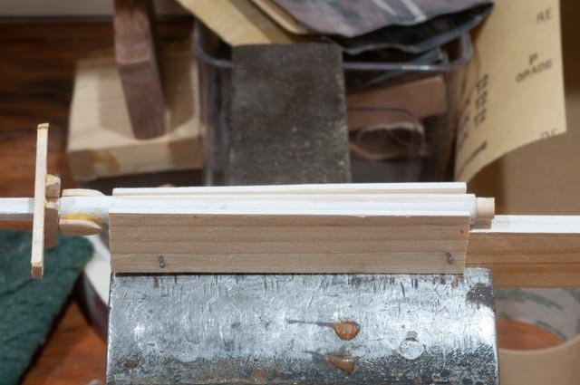
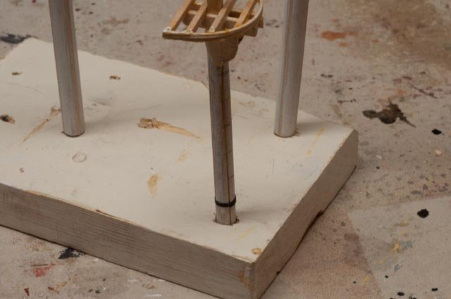
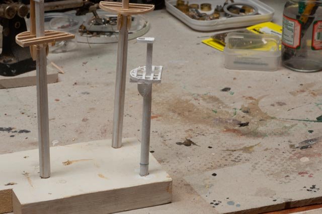
post 12 Lower masts and tops more details to figure out after much study I needed to get back to progress. In this post I went through building the three lower masts and their tops. I learned some things but most important is the need to improve materials, especially wood. Up until now I have been a bass wood, dowels and some pine guy. To get rid of 'fuzzies' and lumpy out of scale wood I need to get into hard wood. It will come, but it seems to be a challenge. A friend gave me a piece of rough pear and I will use a tiny piece as we go through this. I can cut sown to 1/16 so far successfully. I just keep buying strips of 1/32 bass wood I am building a yawl boat for Charles Notman at this same time and there too I am suffering. I leave that discussion for next month when I complete that model and get ready for a showing and lecture. A few related details. Ap 74 Here I took little pins and manually cut the heads and points off and then tried to cut them in two. They were too small for me to file after. There are 198 belaying pins on this ship so I thought it was worth a try. They are not glued in, so I can decide if I want to try again to file off the ends or use the 3/16 store bought pins from ModelShipways. I was thinking of trying to touch them with a file and then blackening them in place. Ap-75 Here we see three yards. The top is the fore lower yard from the model. The hardware is crude but functional. The lowest is broken main lower yard. In the middle I made up a yard for replacement. I made a similar crude fitting. So far, I don’t like it and will try to go with something more like the drawings. I will need some bands on the mast for this yard and the futtocks shrouds, and that makes the most sense. The masts Ap-76 here I have roughed out the doubling and hounds. The length is based on the Crothers calculations. He also gave details on the framing. Ap-77 here we see the sizing template. This was interesting as the figures say just over ½ the width but on the many examples that included dimensions it was always less. I settled on 12 feet for the two masts and 9 feet + for the mizzen. Ap-78 then one needs to find things in the shop to use to bend wet wood to get the rim. I read all about boiling and steaming from the real pros. I boiled and steams and broke many pieces and the went back to bass wood in ammonia water over night to get the pieces. It worked! Ap-79 here a compass and lines on pine allows pinning the pieces together. Ap-80 I made up this little gig to hold the masts to use a combination of razor saw and files to make the 4 groves in each mast to replicate the made up profiles. Ap-81 I used old 1960 vintage drafting tape we used in college architecture classes to make straight bold lines. [ no auto cad then] I have a box left over and a few are 1/16 black so they perfect model supplies. My plan is to paint it over as part of the mast paint which seems to be more common in artwork. Ap-82 here we see the first mast painted white. I think the painted tape works for the bands. Ap-83 here is my first attempt to mill my own hardwood. This is simple maple bought at Lowes. I also used the big table saw to cut a piece of elm to one inch by 1/8 and then cut a small strip to use for fairlead planks. Ap-84 Here we have the tops dressed out and planked over tops with the top mast loosely set in for looks. Ap-85 here we see the dark pear planks that is drilled. The real ships and more accurate model would have 33 holes stagger drilled on this plank. I simply drilled 13 holes so I can run perhaps toping lines through if I get that far. the caps are built up styrene. the tops remain loose so i can set them level with the raked masts. Ap-86 here we see the 14 eyes on each top. There are also predrilled holes for the futtocks shrouds that come next. In these last few close ups one sees the roughness of the filed and sanded dowels [ square tops] and the bass wood planking and beams. This is an area that needs more and more practice to get right. I am sure that the easy to use acrylic craft paints also hurt. I used a little cherry stain on the top masts and just hand rub poly on the tops and over stain. I would love to get to milling 1/32 maple planks for this type work Cheers
-
I am sitting here after three weeks of little wood work. I caught a cold and spent my many hours surfing building logs and more reading. I loved the new book Barons of the Sea a concise history of the owners, builders, and captains of the american clipper ship industry. I then did a lot of further reading and wow am i going down a rabbit hole. I read Ed Tosti's blog...wow such incredible study and workmanship. I am up to page 72 so a long way to go. I am also now reading other blogs and they are all taking my breath away. I just ordered Ed's first book, so at least I will have a great library. This is the 1:48 Flying Cloud that a friend brought over to get some help on fixing up. the model was built many years ago and is way off in scale as to bulkhead, pin rails etc. I am helping him get the masts and spars right, so next winter he can get those on. That project is how I got into Bradner's on line drawings. The owner is happy with simple dowels. I would spend days making made up and banded masts....crazy. My head is spinning...options. what is it I want to do. build large scale radio sail boats but keep them simple...I have one 50 inch Schooner I never finished plus a few Marblehead Vintage AMYA boats build large scale radio sail but put too much detail in them, so they are retired from sailing...I have two of these and in reality 4 including the 42 inch BHODs. build small scale like this build. My fingers and experience keep much detail from appearing. example that I am working on today.... things like the head cap. the real ones I have read were blocks of elm, maybe a foot thick by two feet and four feet long. what wood can replicate that at 1:96....... I have yet to graduate to milling my own pear etc. do I need to learn how to machine metal or cast . wow I am building up with styrene and super glue. we'll see do i try to slice the lower masts to be obvious buildups before banding? do I then put little plus under each band?..... there are 30 fairleads through the tops. Do I drill them? can you see them? I won't be rigging all those lines but even topping lifts for the yards need to go through them...... I could build a large hull like the one photographed here in a few months. I could then make parts like before. then however I have a another 7 foot model. the masts though could be real. I think I will just plod along knowing this is a real early learning curve. anyway I just want to record this mental process cheers
-
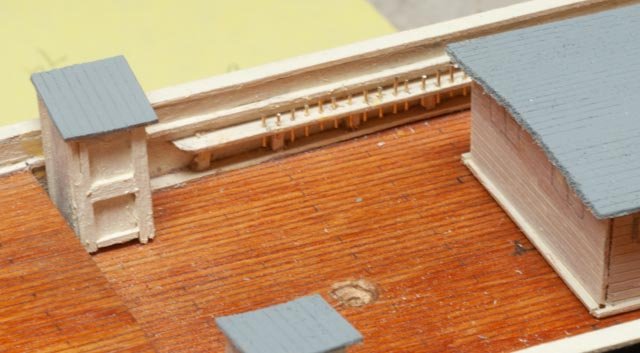
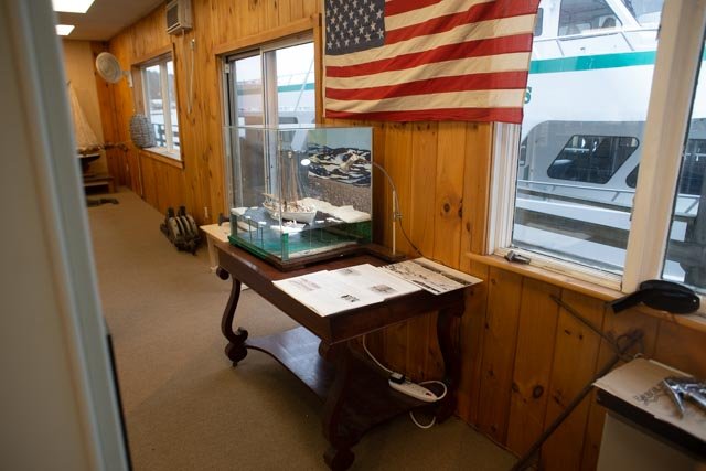
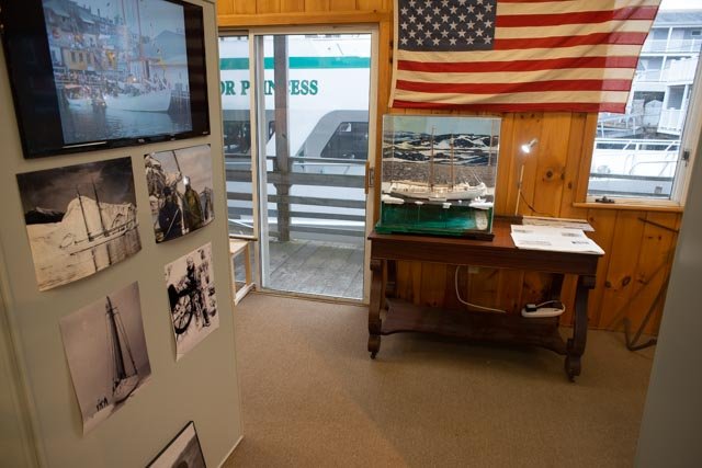
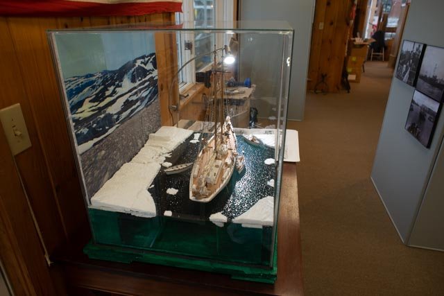
Post 39 The museum We finally made it. There is a lot more to do in set up, as Mark and Diane are two weeks from opening 316 a-d : these four pages are the draft for final editing and are to will be pasted on foam core as placards. They shall try to capture the story to go with the diorama, and will hang on a black cloth above the model[ where American flag is now] to help tell the story. 317 here we enter and see Bowdoin. The dock just out the window is where Bowdoin was tied up before leaving on several occasions. It is part of what makes this story so much fun 318 looking straight on one sees a kiosk where many visual items will tell of Macmillan and the trips north 319 even with all the ambient light I see enough of the sparkle on the water to be very satisfied with the experiment to use the small spot light as part of the display 320 This photo shows the two Canadian built Schooner models that I repaired for the show. The Bluenose on the right and the Herman Zwicker on the left. The Herman Zwicker was a resident of Boothbay Harbor for many years. She was often on display at Maine Maritime Museum. She is today in New York city and her sister schooner is on display in Lunenburg There are several other models and lots of good eats near by, so come visit us this summer Cheers


-
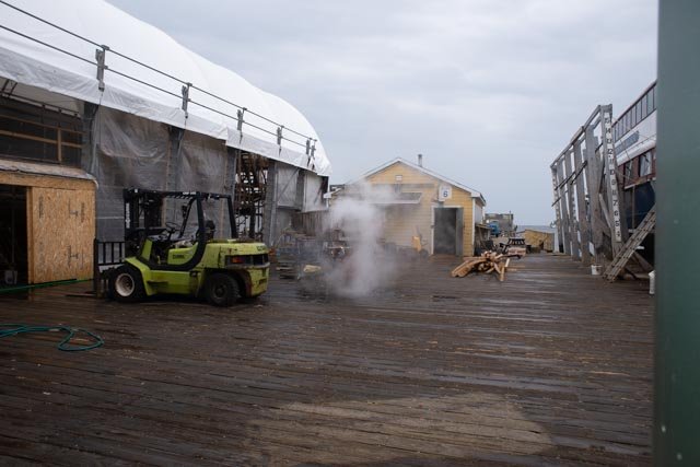
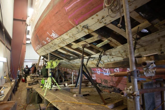
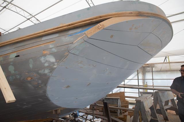
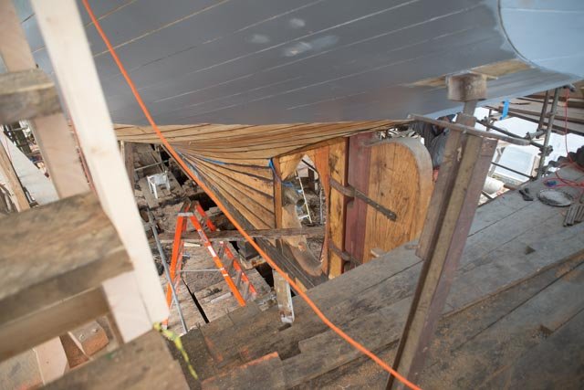
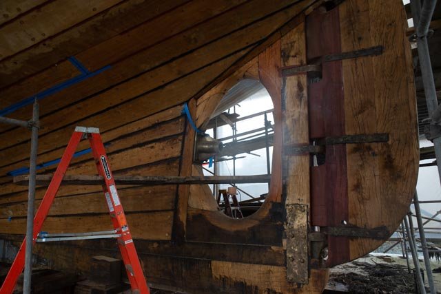
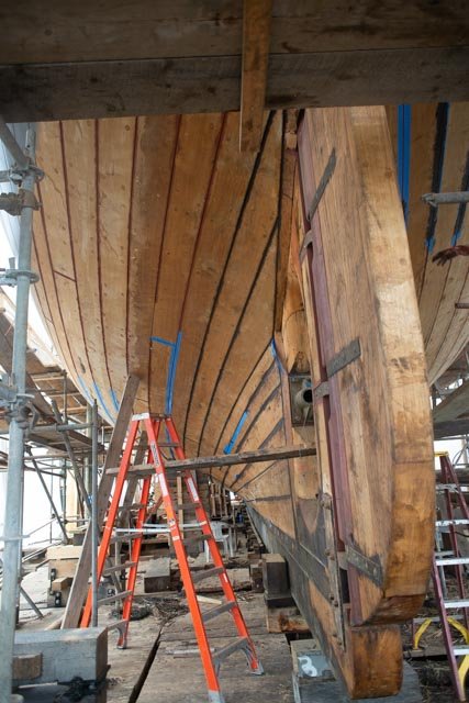
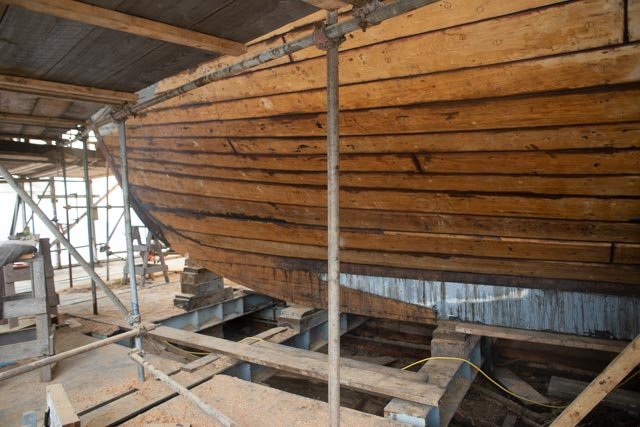
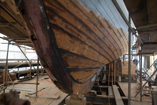
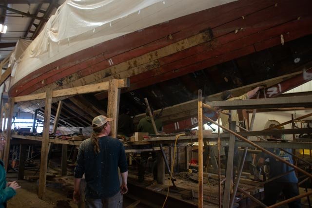
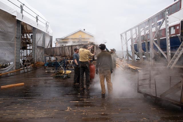
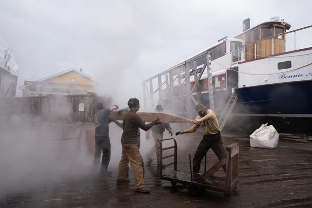
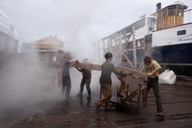
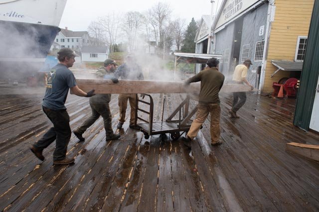
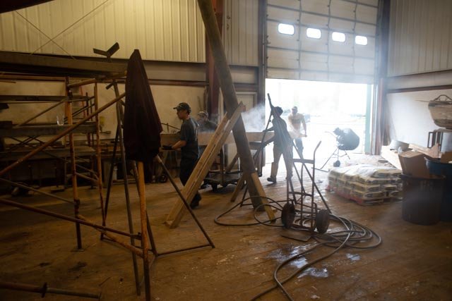
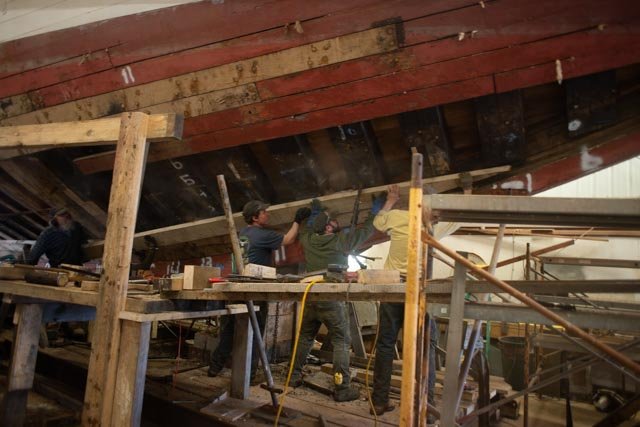
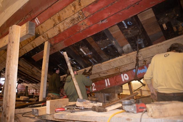
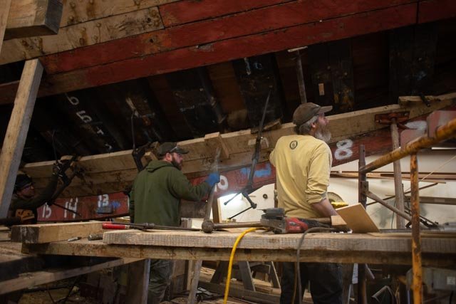
Post 38 Real Bowdoin gets planks 308 here I am on the dock in Boothbay Harbor where the real Bowdoin is getting her hull fixed up. The steam box is cooking the next plank. 309 as I turn around, we see the progress on the new planking. Some 40 frames were replaced and somewhere around 80 planks are being replaced The Ernestina Morrisey Before we see the new plank installed, we catch up on the Massachusetts state schooner also being completely rebuilt here in Boothbay. I share many pictures a few months ago. Today the final caulking is being installed before the hull gets painted. Here are come fun shots of the stern and bow 310 here we see the completed transom 311 looking down we see the progress working downward to get caulking in and prime paint on 312 how about the combination of craft skills to complete all of these components.it is wonderful to see these skills are alive and well. 313 just a fun photo looking forward 314 here we see the forward end of the lead keel and work up to the bow stem 315 this bow stem is African hard wood and one of the only pieces reused in the this rebuild. Back to Bowdoin…..it is time for the next plank. 315 a-h -Here is a quick sequence of taking the plank out and setting. They need to do more than one a day to get done and launched wow All for now