

drtrap
-
Posts
904 -
Joined
-
Last visited
Content Type
Profiles
Forums
Gallery
Events
Posts posted by drtrap
-
-
Nice work Jason, absolutely nice work.
Could you please specify the tip (?) with the wire helping place the knot where you want to ?
Thanks.
-
Trying to place on the right (middle) point of the bulwark the posterior edge of the capping rail.
Its pre-shaped posterior arch and bending can't help me at all.
Thinking to leave it as it is, as a so-called lateral "offset", on that place.
Hope to not create additional troubles following next phases...

-
Hi Stergios,
The pillars came as seperate items to the board and therefore can be placed wherever you like. I pinned one to the board and sunk the other to get correct waterline. Same effect could be had with different height pillars but couldn't find suitable ones in stock.
I had to file the jaws pretty extensively with my dremel to get a correct snug fit to the keel though.
Jim
Thank you again Jim.
-
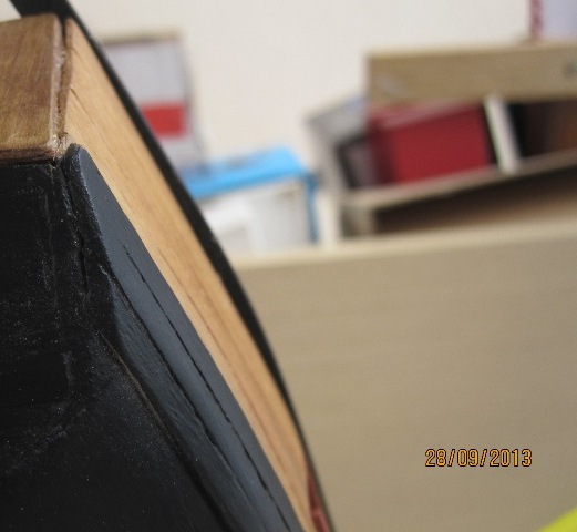
It's one of the Hardwood Mounting Bases by Amati. Comes ready varnished.
Hi Jim
does the distance between the pillars are suitable to that of the keel holes you've opened in advance?
Thanks
Stergios
-
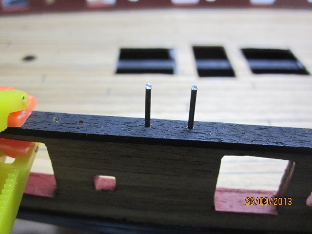
Those shearing lateral forces of the bad-shaped capping rail especially at the stern is a huge headache for me.
I think that using beam or heat is a useless option to decrease the unwanted curvature at the rear edge....
I hope to finally have a nice result with those 1 mm wires....

-
-
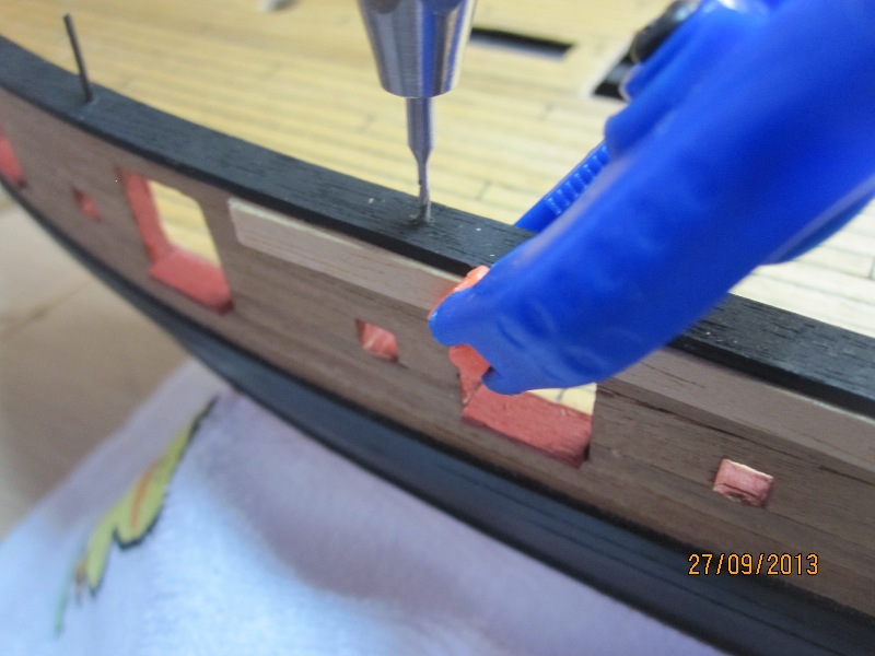
Yes wood filler would allow you to blend it into the wood better and make the hole unnoticeable, why did you want to use glue as a filler?
Pete
I was thinking about glue, only as a coverage of the holes, Pete...
-
Can only speak for my experience, but I'd stick with woodfiller, I use the fast drying stuff which is very easy to use. Glue isn't really made to fill gaps in the way you need it to, so you'd probably still have indentations when its dry that need to be taken care of.
Thank you Jason.
Any recommendation on the type of fast drying stuff?
You know, local products are'nt the same and personal experience is highly required..!
-
Thinking of use carpenter;s glue to cover those 1 mm holes before the final painting instead of wood filler...
What;s your suggestion?
Thanks

-
The whole procedure finally was so easy. I used the 0,25 line for the rigging.
Next step: the capping rails....
- Jobbie, JayCub and Beef Wellington
-
 3
3
-
I used 0.25mm rope, I also recommend winding the rope round the wheel and sealing with watered pva before anything is fixed in position.
Cheers,
Pete
Thanks Pete, I'm thinking to start from the tiller the rigging, going bilaterally to the eyelets/blocks and finishing at the wheel....
-
I used the .25mm line. On your question on the front patform, who am I to judge
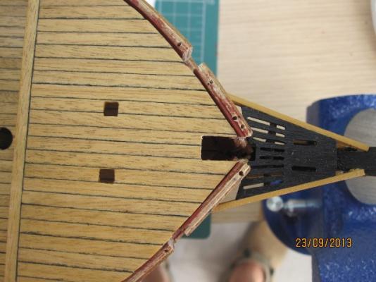
 There really seems to be no guidance, I made the assumption that the deck would fit around the bowsprit, but there are still gaps. Maybe just see how it looks with the bowsprit in and you can decide if you like it or not?
Thanks again Jason.
I thought that you used the 0,1 line, I think I read yesterday your thosedays post....
-
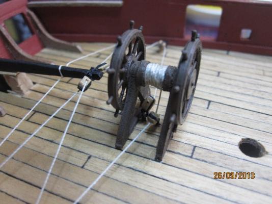
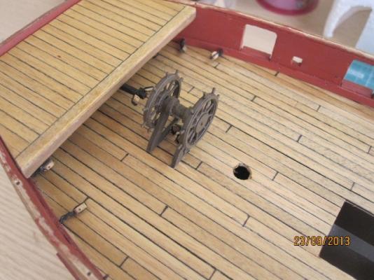
The wheel in place, finally.
A question still in debate: the rope for the wheel... Should I use 0,1 or 0,25 line for the rigging?
And something for the front platform: is it a major fault to leave it's gap (for the bowsprit) rectangular than to shape it in a semicircular fashion, like you did ?
-
-
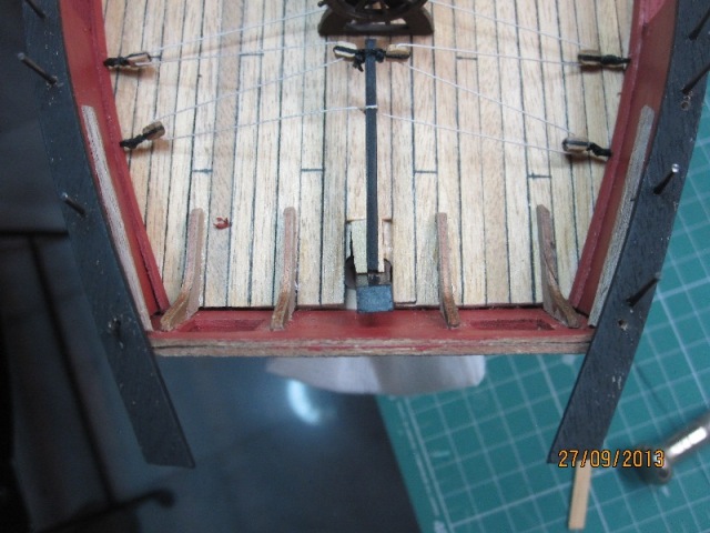
Looking good, big step to attach the wheel! Forgive me for posting a photo, but thought it might help show where the steering tackle and the carronade rigging ended up on mine....not much space at all and don't think there is much of an alternative! Looking forward to seeing some more updates.
You're always welcoming, Jason.
Thanks for the photo!
-
Small quick update... and ready to fix the wheel on the deck
-
Nice tutor Jim!
Absolutely helpfull
-
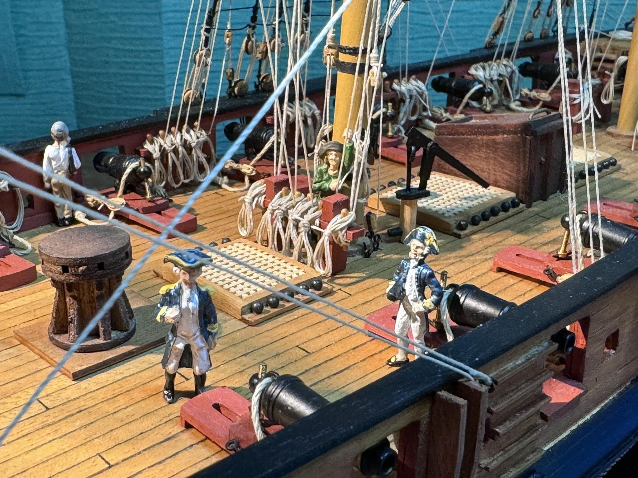
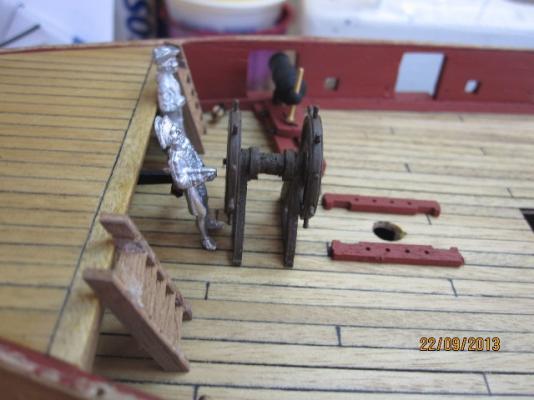
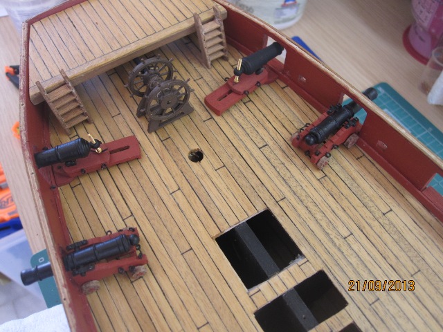
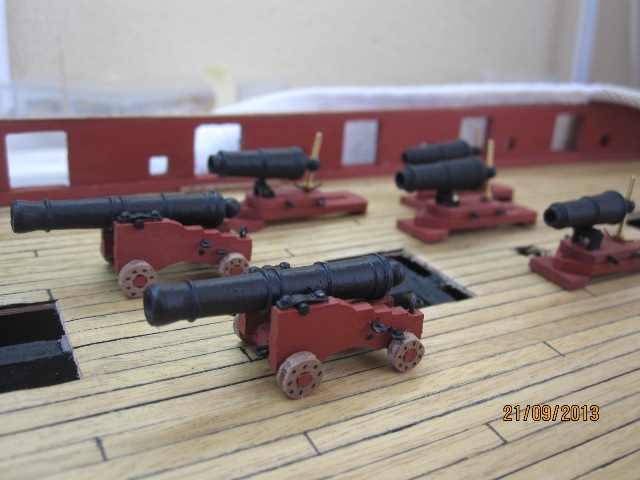
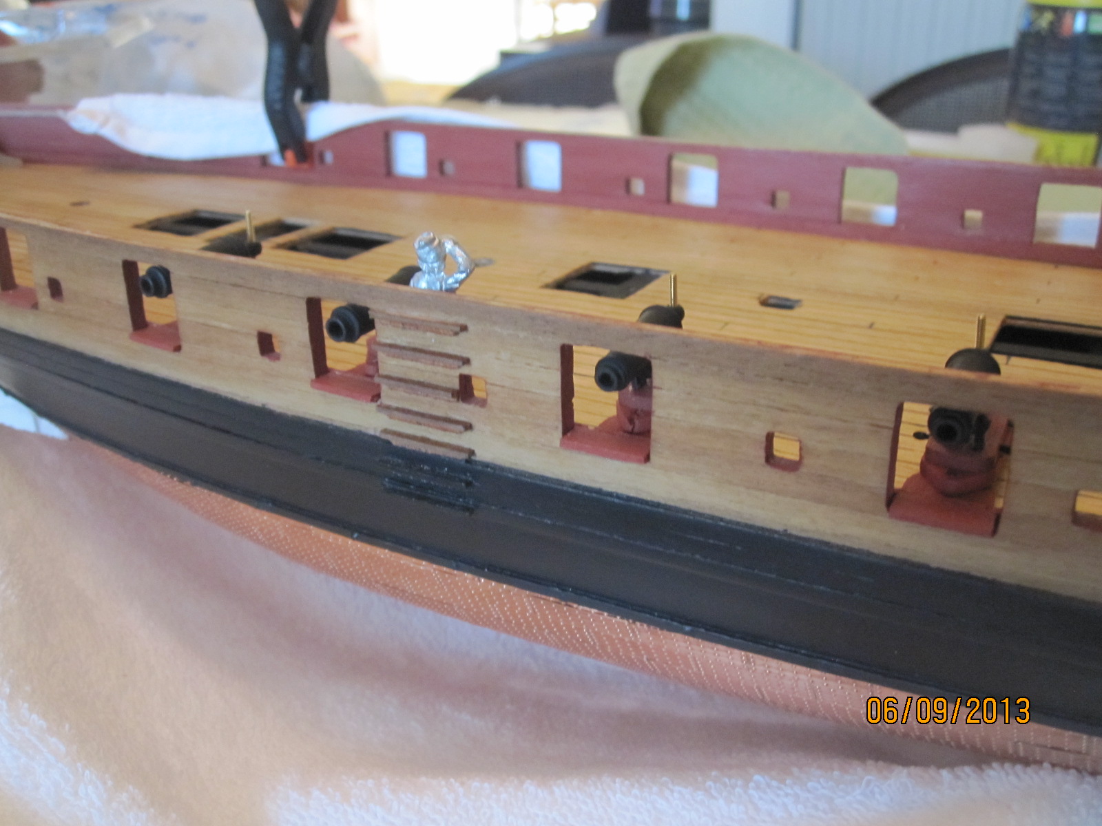
Nice little arsenal you have there Stergios! I had much more fun with the cannons than the carronades. Bottom line, there is very little room on the deck at the stern, the plans are hopelessly out of scale, and you're right it does take some playing to get it all making sense. One thing that can buy you some room is to reduce the height of the ladders so they remain flush with the aft platform decking - there are some photos in my log which may help http://modelshipworld.com/index.php?/topic/509-hms-snake-by-beef-wellington-caldercraft-scale-1-64-first-wooden-ship-build/page-21#entry95246. Apart from being a bit more intuitive, this also has the benefit of giving you a bit more space. The tiller ropes do come very close to the ladders.
Yes Jason
I tend to reduce the height, I placed the ladders uncut and temporarily....
I can imagine you've opened the holes for the breeching so close to the eyelet's hole for the wheel....
-
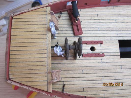
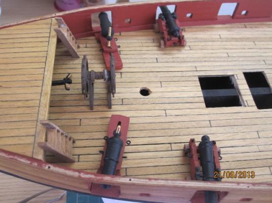
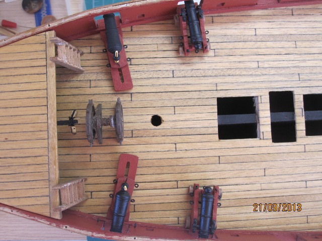
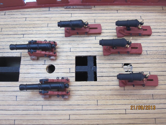
So realy difficult to place all the deck fittings back here...
Especially to find the right spot to drill the front holes for the eyelets of the wheel rigging, because of the holes of the last caronnade.
I think I need to study your previous photos mates!
The fittings are placed temporarily of course...


- JayCub, tuciship and Beef Wellington
-
3
-
-
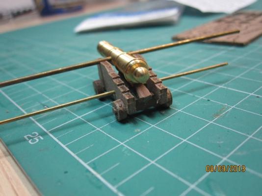
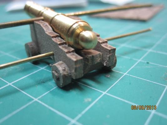
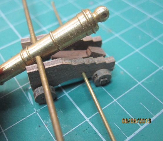
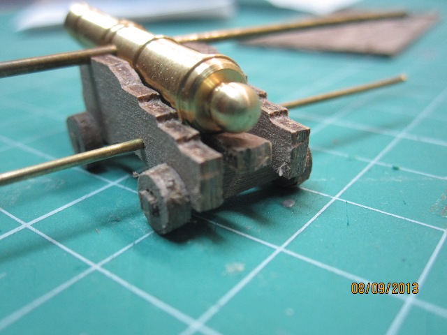
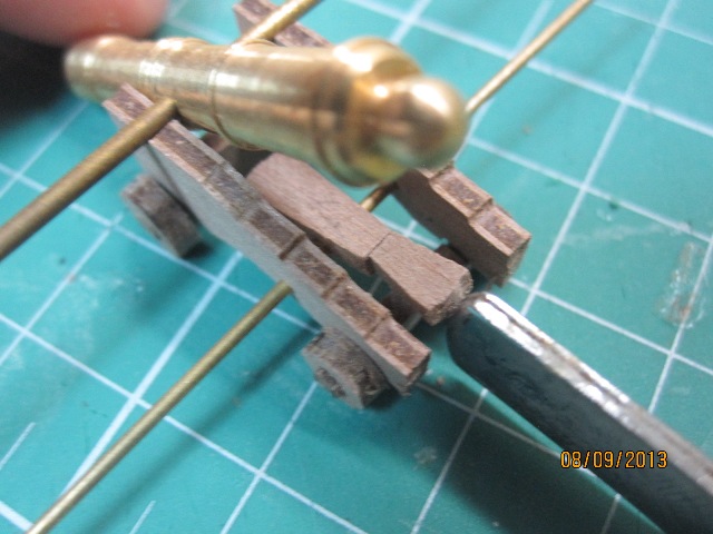
Hopefully these help, view from the top and bottom. Unfortunately these are assembled so its difficult to get a clear view. You can see in bottom picture how the bed sits on the cross bar and the axle frame so that the small slot sits on the bar. The quoin sits on top of the bed, see top picture. I shaped this a bit so it is a true wedge as it would have been, its important to get the quoin placed and shaped correctly to allow the barrel to align correctly.
One thing to note, the hole in the cannon barrel that wire is inserted in to make the pommelions is not centred, which is historically accurate. Before gluing the cannon barrel into place, I'd play around with the quoin and the cannon barrel to make sure that you get the alignment you want on the ship.
...everything is so clear now....

Cheers
-
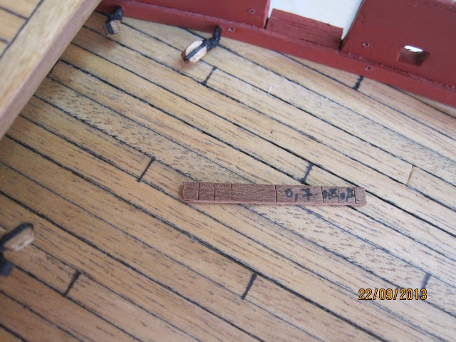
Stergios, the bed is the larger of the two wedges you have cut out, the smaller is the quoin. There should be a small groove at one end, that sits on top of the metal rod you've already fitted, the other sits on top of the rear axle frame. Hope that helps.
Thanks Jason, I'm still trying to fit those tiny parts. I;m not so sure about the orientation of the quoin.
Should I place it onto the bed or "in line" with it? In a vertical or horizontal placement?
The instructions are'nt so helpful, as you know....


-
-


HMS Snake by drtrap - Caldercraft
in - Kit build logs for subjects built from 1751 - 1800
Posted
Thank you mates for encouraging!
Well, I'm about to fix the platforms and glue the capping rails in place.