


Senior ole salt
-
Posts
393 -
Joined
-
Last visited
Reputation Activity
-

 Senior ole salt reacted to Chuck in 18th century English Longboat by Chuck - FINISHED - c.1760
To start...the slotted false keel was tapered from the bearding line to the outside edge. This created a simulated rabbet once the two keel pieces were cut to shape and glued into position.
Then the 16 bulkhead frames were added. I had these laser cut to save time. They were designed in a way that the center sections are removable. They are held to the frames by small tabs. Once the hull is planks I will file through the tabs and snap out the center sections. Care must be taken to square up the bulkheads with the keel and ensure they are straight so the the proper hull shape can be obtained. You could further stabilize the bulkheads by gluing a temporary batten across the tops of them which will be removed before I start filing the center sections free. But I am not a heavy handed builder so I just started fairing the hull immediately. I use d alight touch while beveling the outside edges of he bulkheads. The transom and bow fillers were added just prior to the start of planking.
-
Senior ole salt reacted to NAZGÛL in Wasan 1628 by Nazgul - FINISHED - Billing Boats Vasa 1:75
Hey all, I now finished the railing/balustrad.
There are some interesting differences between Landström, the 1:10 and the real ship. The Landström version is in the previous post.
Here is the 1:10 with likeness of the setup of the herms like Landström, 8 of them. Its also pretty straight and not very curved:
And here is the real ship with a different setup, leaving a space at the edges so the crew can walk there easyer. It also have spacers between the kranbalkarna/catheads and the railing. It has spacers and It's also very curved:
And finally here's my result. I tried to make my railing like the real ship. It didnt allow me to do the spacers though as it would have ended up way to high.
/Matti
Edit: Just checked the plans sold at the museum and that railing is also different to the above versions. It has ten herms and sits pretty tight.
-
 Senior ole salt got a reaction from SGraham in Display case wood
Well I found, at least for me, the ideal hunk of wood for my weathered looking display case base.
It was 12"x3'. Now 8 1/4 W. by 28" L by 7" H.
I think it's cherry and surprisingly sound under all that grey. I had to rip 45o cuts all around to reverse the pieces and glue them back on to preserve the weathered look. The short ends needed a veneer of 3/32 glued back on. The boat is elevated 1 3/8" by means of a 6/32 FH steel bolt in a brass sleeve.
I reinforced the inside of the bilge and drilled and tapped it to receive the bolt. The floor board will cover the bolt end.
I had on hand an imitation Sperm Scrimshawed whale tooth that I decided to be in the display.
I drilled into the base and tapped it out to receive a 2".. 10/24 steel bolt, which holds it erect on the base.
A local plastic shop cut the pieces for the case (not shown). I glued it together with little trouble doing only one side at a time.
Now all I have to do is to finish the model. Mostly the small whale hunting gear and figure a way to impart a grungy look to the furled sail. Maybe just wipe up the shop floor will do it.
S.os
-
 Senior ole salt got a reaction from augie in Display case wood
Well I found, at least for me, the ideal hunk of wood for my weathered looking display case base.
It was 12"x3'. Now 8 1/4 W. by 28" L by 7" H.
I think it's cherry and surprisingly sound under all that grey. I had to rip 45o cuts all around to reverse the pieces and glue them back on to preserve the weathered look. The short ends needed a veneer of 3/32 glued back on. The boat is elevated 1 3/8" by means of a 6/32 FH steel bolt in a brass sleeve.
I reinforced the inside of the bilge and drilled and tapped it to receive the bolt. The floor board will cover the bolt end.
I had on hand an imitation Sperm Scrimshawed whale tooth that I decided to be in the display.
I drilled into the base and tapped it out to receive a 2".. 10/24 steel bolt, which holds it erect on the base.
A local plastic shop cut the pieces for the case (not shown). I glued it together with little trouble doing only one side at a time.
Now all I have to do is to finish the model. Mostly the small whale hunting gear and figure a way to impart a grungy look to the furled sail. Maybe just wipe up the shop floor will do it.
S.os
-
 Senior ole salt got a reaction from Timmo in Display case wood
Well I found, at least for me, the ideal hunk of wood for my weathered looking display case base.
It was 12"x3'. Now 8 1/4 W. by 28" L by 7" H.
I think it's cherry and surprisingly sound under all that grey. I had to rip 45o cuts all around to reverse the pieces and glue them back on to preserve the weathered look. The short ends needed a veneer of 3/32 glued back on. The boat is elevated 1 3/8" by means of a 6/32 FH steel bolt in a brass sleeve.
I reinforced the inside of the bilge and drilled and tapped it to receive the bolt. The floor board will cover the bolt end.
I had on hand an imitation Sperm Scrimshawed whale tooth that I decided to be in the display.
I drilled into the base and tapped it out to receive a 2".. 10/24 steel bolt, which holds it erect on the base.
A local plastic shop cut the pieces for the case (not shown). I glued it together with little trouble doing only one side at a time.
Now all I have to do is to finish the model. Mostly the small whale hunting gear and figure a way to impart a grungy look to the furled sail. Maybe just wipe up the shop floor will do it.
S.os
-
 Senior ole salt got a reaction from Mirabell61 in Display case wood
Well I found, at least for me, the ideal hunk of wood for my weathered looking display case base.
It was 12"x3'. Now 8 1/4 W. by 28" L by 7" H.
I think it's cherry and surprisingly sound under all that grey. I had to rip 45o cuts all around to reverse the pieces and glue them back on to preserve the weathered look. The short ends needed a veneer of 3/32 glued back on. The boat is elevated 1 3/8" by means of a 6/32 FH steel bolt in a brass sleeve.
I reinforced the inside of the bilge and drilled and tapped it to receive the bolt. The floor board will cover the bolt end.
I had on hand an imitation Sperm Scrimshawed whale tooth that I decided to be in the display.
I drilled into the base and tapped it out to receive a 2".. 10/24 steel bolt, which holds it erect on the base.
A local plastic shop cut the pieces for the case (not shown). I glued it together with little trouble doing only one side at a time.
Now all I have to do is to finish the model. Mostly the small whale hunting gear and figure a way to impart a grungy look to the furled sail. Maybe just wipe up the shop floor will do it.
S.os
-
 Senior ole salt got a reaction from KevinR in Display case wood
Thanks mark for your suggestions. They are good ones for sure.
My intention is to have it look like it is ready to hunt whales. That is one harpoon at the ready. Also to enable the viewer to have some eye candy and to see the various boat gear, which is quite numerous. The oars will have to be in the locks but the blades extended past the gunnel. To give the viewer a sense of scale, the ships cat will be somewhere in the boat stalking a rat (also aboard) this will give the viewer a reason to scan the innards of the boat. I'm thinking this will add a little fun to the display.
If I build the Bounty's launch, the beach idea would be a good one as the good captain Bligh did land on the great barrier reef and also on the Island of Tofua.
S.os
-
Senior ole salt reacted to Gregor in HMC Sherbourne 1763 by Gregor – FINISHED - Caldercraft – Scale 1:64 - first build
The pin rail situation has been partially solved. There was room for 6 additional pins on each side, five holes can be seen here on the picture. I added another very small piece of wood towards the bow, with a hole for one more pin.
I made also a pin rail under the bowsprit, with four pins. My archaic windlass offered no possibility to ad something there. If the rigging develops a complexity that I cannot imagine at the moment, there will be room for more pins on both sides at the bulwark. And yes, the windlass has now standards – when looking at Dirks log I decided not to take a shortcut here.
Sunday afternoon I spent soldering. The brass swivels are from Caldercraft, treated as shown in Dirks log. My stanchions are simpler, though. I soldered small rings to a brass wire (0.8mm).
The problem now is blackening. After trying out the solution by Krick, I got a better result with a mixture prepared by a local chemist: It works perfectly with brass, less so with soldering leftovers. Stanchions, handles and pintles I will have to paint, the swivels themselves are almost clean, with traces of rust … With the big guns I will be extra careful.
Chers,
Gregor
-
Senior ole salt reacted to Modeler12 in A video about attaching shrouds, deadeyes, etc.
Thanks Max,
I could have added one more thing and that is the alignment of the deadeyes. For this video I premade the two shrouds and proceeded from there. For an actual model the shroud lines would already be attached to the mast on top and the length would be adjusted at the deadeye at the bottom of the shroud.
To do this I have used a simple fixture shown below.
The two nails you see in the middle were used for some other shrouds higher up, so ignore them for now.
I take the fixture and slip it onto the bottom deadeye and clamp it in place. Then I put the top deadeye onto the nail and wrap the shroud around the groove in the deadeye. A drop of CA glue holds it in place and then I apply the seizings.
I hope this all makes sense because I only show the whole thing in place.
-
Senior ole salt reacted to Modeler12 in A video about attaching shrouds, deadeyes, etc.
I am in the process of attaching more shrouds to my Connie and thought it would be good practice to make a mockup to show what I was doing.
Here is the result.
-
Senior ole salt reacted to KennyH78 in Young America 1853 by EdT - FINISHED - extreme clipper
Love your work, Ed. I learn something new each time you post an update. Keep at it and I can't wait for more!
-
Senior ole salt reacted to EdT in Young America 1853 by EdT - FINISHED - extreme clipper
Young America - extreme clipper 1853
Part 43 – Bilge Ceiling, Iron Strapping
Historical Clipper Note: A number of different structures were installed inside clipper ship hulls to increase strength and help defeat hogging, the most serious structural threat to wooden ships apart from rot. Hogging is the tendency of hulls to droop at the ends. It resulted from the reduced buoyancy at the ends of ships as the flotation area of the hull got smaller. It was further aggravated by localized stresses as waves passed under the hull. This was a particular problem in clipper hulls that were very long and had very fine lines fore and aft.
In addition to large keelsons, weight reductions at the ends, moving foremasts aft and some features discussed in earlier posts, additional structural members inside the hull were also used. These varied from builder to builder. These included massive additional keelsons in the area of the floor heads, various forms of heavy ceiling timbers, long diagonal wood “pointers” and ironwork. From what we know of William Webb’s designs, he seemed to favor thick “bilge ceilings” – bands of heavy planking from below the lower futtock heads up to the lower deck clamps - rather than bilge keelsons or pointers.
An 8” to 7” thick bilge ceiling and iron strapping were the most likely combination used in Young America and that will be the configuration I will use on the model
After some deliberation – discussed in earlier posts – I finally decided to install the strapping on the inside of the frames. Although this is not known to be the original configuration, it is most likely based on some references and Webb’ practice on other ships.
The strapping was installed on the frames under the ceiling planking. Because installing the strapping requires some hammering on the frames to rivet the straps in place, I wanted to get a couple of ceiling strakes in place to make the frame structure stronger before beginning the strapping.
The first picture shows the first strake of the bilge ceiling being installed. These are 8” x 8” members bolted through the frames from a few feet above the floor heads decreasing in thickness to 7” up to the lower deck clamp
The strake being installed is at the heads of the lower futtocks. This strake and the others in the band, follow the curve of these futtock head joints. Fore and aft they converge under the lower deck clamp to form a sort of truss to resist bending of the hull. This was definitely the configuration when bilge keelsons were used and it is likely the bilge ceilings followed this practice. Once this line is set by the first strake the others above and below it will be installed.
The next picture shows a closer view of the bolting and one of the joint scarphs.
Copper wire bolts have been epoxied through the frames. The dark area is isopropanol used to wash off the epoxy – not yet dry. Epoxy will help assure that the wire will act as true through bolts. In practice these were iron, so they will be blackened before final finishing. The second bolt at each frame pair will be modeled using black monofilament.
The next picture shows the copper bolts coming through the frames outside.
These will be clipped off and sanded flush as part of the external fairing process. It can be seen that the bolts come through the lower futtocks just below the heads. I am considering leaving a few view ports on the exposed framing side of the hull. The bottom of these open areas would be at the floor heads, so the bolted inside members should provide plenty of strength around the openings. The tops of these openings will probably be at the middle deck clamps.
With a stretch of ceiling in place I was anxious to try out some iron strapping. The first picture shows the installation of a test area.
I decided I wanted no part of recessing all these into the frames. For the most part they will be covered with inboard planking and will only be visible between frames on the outside, through the view ports if installed, and down through unplanked deck areas.
The next picture shows a closer view of the straps and their fasteners.
I used .005” copper for the straps, cutting them to size with a paper cutter, and then stretching to straighten them. I considered using .010” strips but these would require recesses. The thinner material should not affect the planking glue joints. Planks will also be bolted so should be quite secure. The difference in thickness is virtually undetectable visually. The actual thickness would probably be somewhere between the two sizes.
The straps are held in place by copper rivets - 22 gauge copper wire – some through and some partially through as “blunts”. Like the real bolts, the heads are peened over to secure the strips. I initially tried to get all of the intersections on frames for bolting, hence some uneven spacing in this first area. I will not describe all the steps in detail – or the journey up the learning curve to get acceptable-looking straps.
These must of course be blackened before being planked over – to avoid glue spots that would interfere with the etching.
The next picture from outside the hull shows some strapping blackened using liver of sulfur solution. This will be the predominant viewpoint for this feature.
This picture shows some inevitable crossing of straps between frames. I doubt that I will try to rivet these intersections as was done in practice, except where they fall over a frame. A few strapping rivet heads can be seen on the outside of the frames.
The strapping will be installed over the full length of the hull up to the upper deck clamps. The next picture shows some correctly sized clamp material – for the lower and upper decks - temporarily held in place,
This shows the convergence of the ceiling and the lower deck clamp mentioned above. The 7 to 8” bilge ceiling would fill the area below the lower deck plank and continue for a few more strakes below those installed in this picture.
The straps will be cut off above the upper deck clamp. The strapping is fully extended forward in this picture. The middle deck clamp will fall midway between the two shown.
I now foresee a considerable amount of strapping work, punctuated with some bilge ceiling and perhaps deck clamp installation. Should be interesting.
Ed
-
 Senior ole salt got a reaction from popeye2sea in Whale boat eye splice
Yes I did Jay.
I went to specialized lumber store that saves old barn siding and the like. For 25 bucks I got a great deeply weathered and gray hunk of siding. It measures 1"X 12" X 3'. It even has a few nail holes in it. I'm going to cut it to size *8" wide by 28 ". The rip will be a 45o that will enable me to put the beveled piece ripped off glued on the other side thus preserving the weathered appearance. This piece will project higher than the base forming a lip in which the plexi glass case to fit into. I all ready assembled the case but had the plexi glass dealer cut the pieces. I will post the case when finished along with the still incomplete model. All those little whale hunting gear takes time to assemble.
Thanks for asking
S.os
-
 Senior ole salt got a reaction from Modeler12 in Whale boat eye splice
Yes I did Jay.
I went to specialized lumber store that saves old barn siding and the like. For 25 bucks I got a great deeply weathered and gray hunk of siding. It measures 1"X 12" X 3'. It even has a few nail holes in it. I'm going to cut it to size *8" wide by 28 ". The rip will be a 45o that will enable me to put the beveled piece ripped off glued on the other side thus preserving the weathered appearance. This piece will project higher than the base forming a lip in which the plexi glass case to fit into. I all ready assembled the case but had the plexi glass dealer cut the pieces. I will post the case when finished along with the still incomplete model. All those little whale hunting gear takes time to assemble.
Thanks for asking
S.os
-
 Senior ole salt got a reaction from mtaylor in Whale boat eye splice
Yes I did Jay.
I went to specialized lumber store that saves old barn siding and the like. For 25 bucks I got a great deeply weathered and gray hunk of siding. It measures 1"X 12" X 3'. It even has a few nail holes in it. I'm going to cut it to size *8" wide by 28 ". The rip will be a 45o that will enable me to put the beveled piece ripped off glued on the other side thus preserving the weathered appearance. This piece will project higher than the base forming a lip in which the plexi glass case to fit into. I all ready assembled the case but had the plexi glass dealer cut the pieces. I will post the case when finished along with the still incomplete model. All those little whale hunting gear takes time to assemble.
Thanks for asking
S.os
-
 Senior ole salt got a reaction from Piet in Hr. Ms. O 19 1938 by Piet - FINISHED - scale 1:50 - submarine of the Royal Navy Netherlands in service 1939 - 1945
It's fun to watch this build. Keep up the good work and thanks for sharing.
S.os
-
 Senior ole salt got a reaction from popeye the sailor in Hr. Ms. O 19 1938 by Piet - FINISHED - scale 1:50 - submarine of the Royal Navy Netherlands in service 1939 - 1945
It's fun to watch this build. Keep up the good work and thanks for sharing.
S.os
-
Senior ole salt reacted to Keith_W in HMS Bounty Jolly Boat by Cannon Fodder - FINISHED - Artesania Latina - Scale 1:25 - First Wooden Ship Build - SMALL
CF, you need scotch tape which can be marked. Apply the tape to the gap, then use a pencil to trace the outline of the gap. Remove the tape and place it on a plank. Use a sharp knife to trim the tape up to the mark, then cut the plank to fit the tape. Make sure that you do not cut exactly to the outline of the tape - leave yourself some excess, then sand the rest of the plank until it fits the gap.
-
Senior ole salt reacted to EdT in Young America 1853 by EdT - FINISHED - extreme clipper
Young America - extreme clipper 1853
Part 42 – Internal Hull Work
With the hull framing finished it was time to step back and consider the right construction sequence going forward. Rather than go to work fairing and sanding the outer hull as I has anticipated, I decided to focus next on some of the basic internal structural elements. Installing some key internal longitudinal members will add a lot of strength to the frames, in particular the connections of the full square frames at the keel. These joints are rather weak and may not stand up well to outside sanding. In practice this joint was strengthened by use of a very heavy garboard strake (the plank next to the keel) that was bolted up through the floors and lower futtocks. This 9” thick block was in turn edge bolted into the keel. The garboard was a much more important structural member in these ships than the familiar 18C RN subjects.
The first step was to fair out the inboard sides of the frames. The full square frames had been carefully checked for fairness before locking them forever into place when the keelson was installed. The careful pre-beveling of the half and cant frames and the use of the topside ribband to set these resulted in a pretty fair surface. A few had to be removed and reset.
The first picture shows the first sanding/fairing step using 120-grit paper and a “soft-sander” foam pad.
Once all the surfaces were faired out with the 120-grit paper, 220-grit was used to start smoothing the surfaces. In the next picture a round piece of a soft-sander pad is stuck to a vibrating sander and it turn has some 220-grit paper attached to that – all with two-faced carpet tape, A few different pad shapes were used.
This was followed by 320-grit, using the same device. There was also a lot of old-fashioned handwork with all this sanding.
In the next picture the wood is being given a final polish with #0000 steel wool.
I don’t like using steel wool very much – it leaves a lot of steel fibers lying around and this also adheres to steel tools. But after years of searching, I have found nothing that polishes bare hardwood like steel wool, so I am using it here - #1, then #0, then #0000. All the tools are cleared away before doing this and the shop-vac comes out frequently.
With the inside of the hull given its final polishing, the lines of the deck clamps were scored on the frames as shown in the next picture.
A thick pine batten was first clamped to the frames as shown. The heights of the clamps were taken off the inboard arrangement drawing with the calipers shown below. These will be familiar to those who followed Naiad.
To allow the measurements to be transferred to the inside of the hull a thin strip was taped on top of the original arm to fit through the frame gaps.
The next picture shows the batten set at the height of the middle deck. The lower deck clamps on both sides have been marked. The upper (or main) deck clamps will be just below and essentially parallel to the temporary ribbands clamped to the outside of the frames. When those clamps are installed, the outside ribbands can be removed
Removing the temporary ribbands and strengthening the framing with internal members will allow the outside of the hull to be completely faired and finish sanded from the keel up to the top rail.
In the next part members of the “bilge ceiling” will be installed below the line of the lower deck clamp.
Ed
-
Senior ole salt got a reaction from Mirabell61 in Display case wood
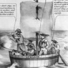
Been thinking about the case for my model Whale boat. I like the look it has on an old beat up looking board like where I took this image:
It will be elevated by plain brass posts as the instruction book suggested.
Has any one here tried this approach in displaying their models ?
If so do viewers agree with this kind of "look" ?
Thanks S.os
-
Senior ole salt got a reaction from Modeler12 in Display case wood
Been thinking about the case for my model Whale boat. I like the look it has on an old beat up looking board like where I took this image:
It will be elevated by plain brass posts as the instruction book suggested.
Has any one here tried this approach in displaying their models ?
If so do viewers agree with this kind of "look" ?
Thanks S.os
-
Senior ole salt reacted to rlb in US Brig Oneida 1809 by rlb - The Lumberyard - 1:48 scale - POF - Lake Ontario Warship
Old business: I have an adapter part on order so that I can put my old hard drive in my new computer, and retrieve all the old photos.
New business: I have a tough time, sometimes, with the "leave well enough alone" concept. The wale on my Oneida has been bothering me since I first put it on, almost three years ago. At the time I was confused about the meaning of this line on the Chapelle drawing:
My interpretation (keep in mind I knew next to nothing, and couldn't find much info) was that it marked a difference in the wale between a strake of "straight" planking above the line, and top and butt planking below. How silly. But that's the way I built it.
I now believe (having seen a little more of the shipbuilding world) that it indicates a change in the thickness of the wale. Below is a sketch of the wale as built, with a dashed green line showing how I think it should have been built--
I just couldn't leave this alone, so work was begun to change it--
Looks pretty ragged here--
But better after sanding--
During the staining process--
And the result after one coat of finish--
I probably didn't take it down quite far enough, but I'm satisfied that at least the difference is there now--
There's not much rhyme or reason sometimes to the things I "need" to fix, and the things I let go. This one fell in the former category but now I'm happy and I can move on!
Ron
-
 Senior ole salt got a reaction from avsjerome2003 in Display case wood
Been thinking about the case for my model Whale boat. I like the look it has on an old beat up looking board like where I took this image:
It will be elevated by plain brass posts as the instruction book suggested.
Has any one here tried this approach in displaying their models ?
If so do viewers agree with this kind of "look" ?
Thanks S.os
-
Senior ole salt got a reaction from Modeler12 in USS Constitution by Modeler12 - FINISHED - Model Shipways
Fantastic build. I also admire your diligence in photographing your progress and sharing here.
Thanks
S.os
-
Senior ole salt reacted to Modeler12 in Another type of blackening agent and some experiments
Here is one more experiment. The question was raised about cleaning brass wire before blackening. I know that some wire you buy in craft shops has a polymer coating to prevent tarnishing. But what about some of the others?
Here is what I did. I took samples off three kinds of wire.
1.Steel wire used by florists. This happened to come from China.
2. Brass wire from a craft shop.
3. Copper wire I had lying around and I have no idea if it was coated or not.
One of each I used 'as is', the other piece I 'cleaned' with some steel wool. Then I dipped each one in the reduced solution of the patina as discussed above (2 parts water : 1 part patina). I held the piece with my fingers at the end (bottom part) and submerged it for about 10 to 12 seconds.
Results:
1. The steel wires turned black almost immediately.
2. The brass 'as is' had a couple small black spots but really was not affected. The piece I had 'cleaned' had more black showing, but not really enough!!! Hmmmm. . .
3. The copper 'as is' turned black but again not a deep black. The cleaned copper turned uniformly black.
I knew that the brass should have done better. So I repeated the experiment using straight patina out of the bottle. And sure enough the sample I had cleaned with steel wool turned black almost instantly. It only goes to show that the concentration of the solution has a lot to do with the material you are trying to blacken.
My suggestion is: TRY IT YOURSELF.