
HOLIDAY DONATION DRIVE - SUPPORT MSW - DO YOUR PART TO KEEP THIS GREAT FORUM GOING! (78 donations so far out of 49,000 members - C'mon guys!)
×


AON
-
Posts
2,863 -
Joined
-
Last visited
Content Type
Profiles
Forums
Gallery
Events
Everything posted by AON
-
 Darn auto correct on my phone. Not incline .... in line. Apparently age has tripped me up again. I am wrong. They are inline. Apologies
 -
I thought they weren't. Also, I believe the fore and aft trucks (wheels) should not be inclined. The fore trucks are inboard.
-
Excellant work! I believe the officers seats of ease had a discharge tube connection running down to the pointy ornate bit on the underside of the quarter gallery Dumping directly into the water. I remember reading about gawkers getting too close to the Bellerophon When Napoleon was held onboard and getting a surprise.
-
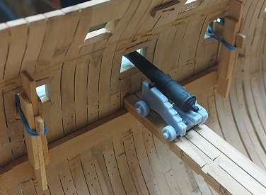
I would prefer to learn from someone else's mistakes except I just don't seem to remember them as well as those I make myself. Since I told one person (and the cat is out of the bag), I have gotten past my damaged pride and so can tell everyone. I got to a point where I could actually put a gun on the gun beam and see it poke through the gun port. The problem was it didn't. The deck was too high. (note the past tense) I double checked my scale on the 3D gun models and compared to the 3D printed guns. Perfect. I double checked the dimensions of the model to the reference material dimensions. Perfect. I checked the height of the deck.... and there it was. I had measured from the underside of the keel to the top of the deck beam, not the underside. This made my clamp location too high, hence the deck being too high. I tore out the gun deck, and since lowering the gun deck makes the gap to the orlop deck too small... I tore it out also. Sanded everything yesterday and recalculated and proved the new deck height today. Orlop and gun deck clamps going back in today, then I get a "do over". Up side: I guess I am not a novice in this area of the build anymore so my results should be more pleasing to the eye. Now I am away until after my "new" anchor cable riding bitts are installed.

-
Some bad news. I will not be posting for some time. Something happened and I would not like to talk about it at this time. I will be back (just like a bad penny), but it will be quite some time. Sorry folks.
-
Anchor riding bitts and small scuttles are done. Now I must decide : do I go forward and work on the hawse hole inboard side, or do I continue aft and work on the stairway to the orlop deck?

-
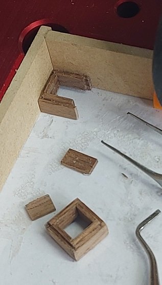
Made the two scuttle coamings. Used walnut for contrast as I wanted them to stand out amongst all the other wooden pieces. Went square shaped at an unconventional 27" because the size looks good and I shifted my ledger beam over about half a thickness. Forward one installed.
-
Swan class 3D model in progress
AON replied to dvm27's topic in CAD and 3D Modelling/Drafting Plans with Software
Excellent! BZ- 141 replies
-
- 2
-

-
- pof swan series
- swan
- (and 1 more)
-
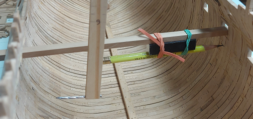
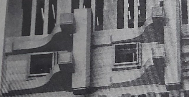
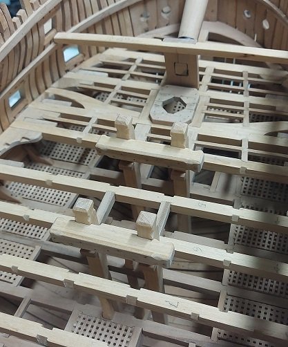
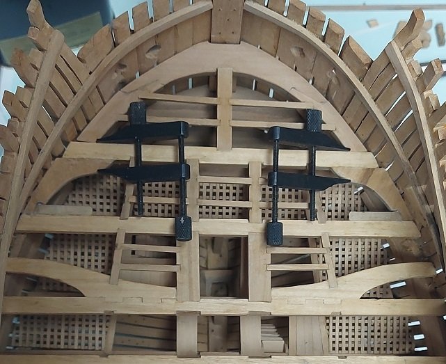
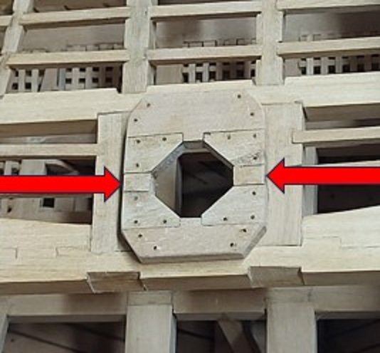
Prior to completing the installation of the aft of the two forward gun deck anchor riding bitt standards (knees), I need to install the carlings and ledges. Prior to doing that, I need to determine the size of the two small scuttles so I will have adequate open area to accommodate them. I found an excellent photo (cropped and posted below) on page 67 in the book: The Construction and Fitting of the Sailing Man of War by Peter Goodwin. It shows the gun deck construction details on a model of the 74 gun ship HMS Egmont. Page 208 states scuttles were just large enough for a man to pass through at either 24 inches square or 24 inches x 30 inches, and they were provided with solid covers. The NMM plan J2930 (Elephant Lines) shows their length fore and aft to be about 27”. The scuttle framing or coaming rises above the deck some 7 inches and they are about 5 inches thick. The lip measures about 2 inches wide x 2 inches high. According the Anatomy of the Ship: The 74-gun ship Bellona by Brian Lavery the forward scuttle is to the gunner’s store room and the aft to the powder room. Peter Goodwin’s photo of the Egmont shows the forward scuttle shifted to port whereas the aft one is centred. The NMM Elephant deck plan J2938 shows exactly the opposite, plus the scuttles are depicted as 30 inches square. So I guess... it is “dealer’s choice”?
-
Swan class 3D model in progress
AON replied to dvm27's topic in CAD and 3D Modelling/Drafting Plans with Software
Sorry, but I've discovered it is the the small things that impress the most. You get 90% of your audience with the magnificent looking sail. The another 9% with the two holes... we were told about them! There is still that 1% out there... those real sailors that see everything. 👀 I'd be impressed to see those holes with the rope grommet sewn around them 😏... a challenge for you!- 141 replies
-
- 1
-
-
- pof swan series
- swan
- (and 1 more)
-
Swan class 3D model in progress
AON replied to dvm27's topic in CAD and 3D Modelling/Drafting Plans with Software
I think the drainage holes are missing.- 141 replies
-
- 3
-
-
- pof swan series
- swan
- (and 1 more)
-
Installed the riding bits (glued in place) with the cross piece eyes and hooks on both sides of the bitt pins, and the standards on the forward riding bitts. I need to install the carlings and ledge beams before I can put the forward riding bitt standards in place. Then I came make the two small ventilation scuttles.
-
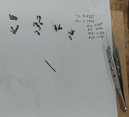
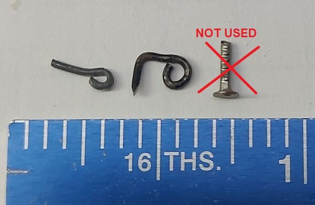
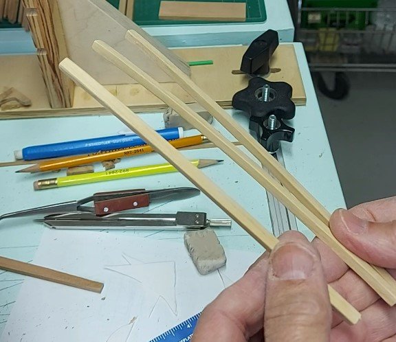
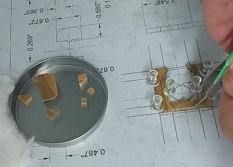
Made my riding bitt eyes, hooks and bolts. The photo below shows the size. The eye and hook is made from black anodized jewellery wire. I had some tiny nails that I thought I'd just snip the length shorter but then realized I had another bag of black anodized jewellery wire that had a flattened head on one end... so I tossed out the nails. You can see the new "nails" in the second picture. The eyes go in the cross pieces. The hooks are nailed to the bitt pieces. I have all the eyes installed. I also made my standards for the riding bitts. They are two pieces rubber cemented together to cut and shape identical pairs. They've been fitted and all edges softened (sanded) and are ready to install. Below is after shaping on the oscillating drum sander.
-
Bitts dry fitted to gun deck beams and cross pieces glued to bitts. Presently working on the cross bitt hooks and the standard knees.
-
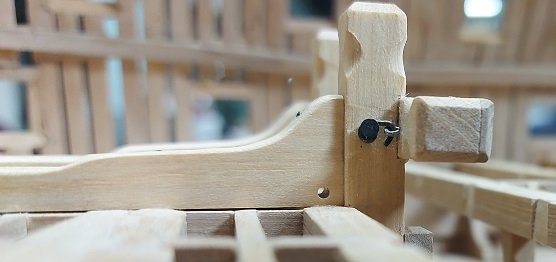
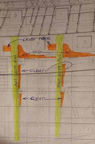
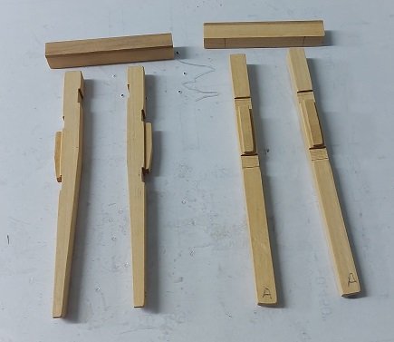
A picture is worth 1000 words! The plan showing the lower cleat and the forward pin bevelled on the forward (right) side whereas the aft pin is bevelled on the aft (left) side per all other references A photo of my parts to date.
-
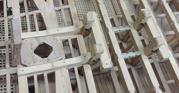
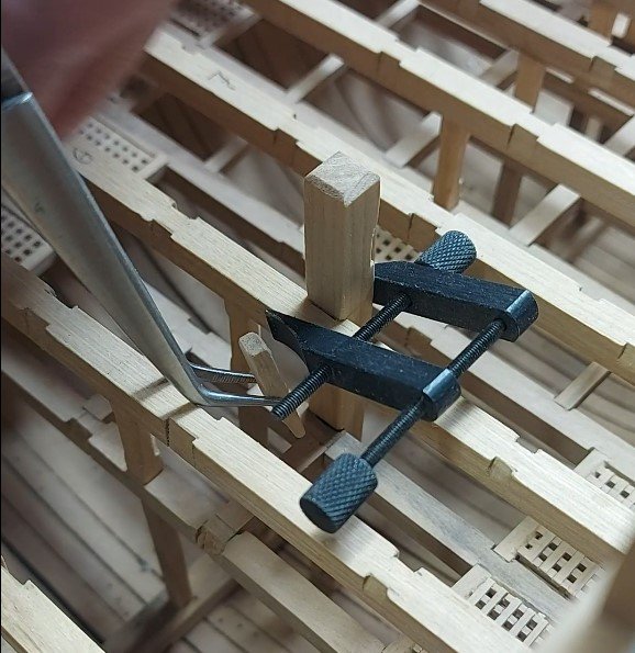
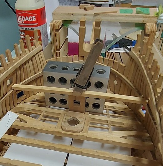
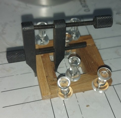
Presently working on the gun deck riding bitts. The plan shows the bitt pins, cross beam, upper cleats (below the gun deck beams) and lower cleats (below the orlop deck beams) and standards (knees). The contract only mentions the upper cleats as do all other references (books). The plan also shows the tapering of the bitt pins but the forward pins are tapered opposite to the aft pins and all other references (books). As it doesn't make sense to taper the forward side of the forward pins as this makes it not set into the orlop beam, I didn't do this. Presently the cross beams are cut and the elm backing piece is glued on. As I haven't any major pieces of Castello left I am now using Pau Marfim (Pau Amarello) wood stock. It is lighter in colour so I found some small pieces of castello to use for contrast as the elm, hence the light and dark pieces. The ends have since been trimmed back. The bitt pins are all made, notched to fit into the deck beam by 2" (0.03" at 1:64), and the head has been chamfered 0.03" at 45°. The (upper) cleats are made, and with the pins dry clamped to the deck beams, the cleats were glued and clamped to the pins. I needed to use my spring loaded tweezers to get them in, and again to get a clothes pin in to clamp them on to dry. My fingers wouldn't fit in the space. Still some work to do to finish these off. There is some shaping to the pins and cross pieces to be done where the anchor cable is meant to wrap around them. Then I have to make the standards and some wire hooks and eyes for the cross beams. I have a problem with how the ledge beams and carlings are supported. The contract reads the carlings are under the standards. I imagine a block was added to the aft face of the bitt pin for the carling to rest on... or the bitt pin had another notch in it to receive the carling. The latter makes it difficult to bolt the bitt pin to the deck beam through the aft face. I think I'll be adding support blocks.
-
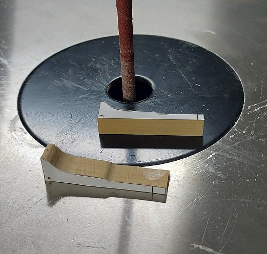
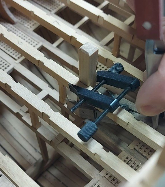
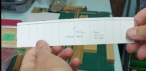
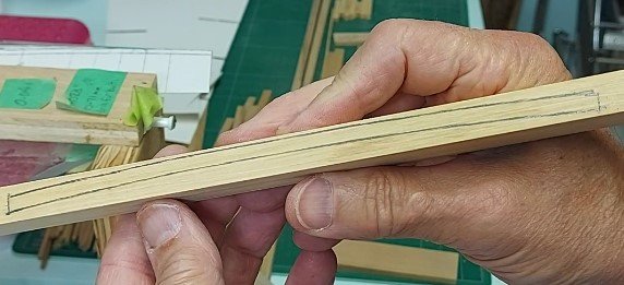
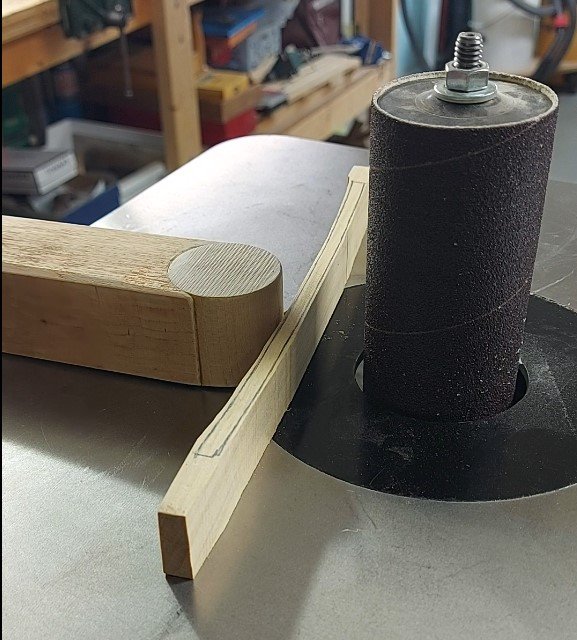
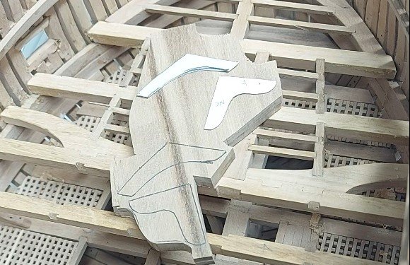
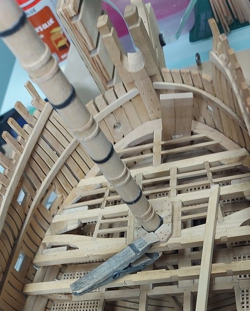
Then I turned to installing my bowsprit step. It is supported on the gun deck beam forward of the partner and the upper deck beam above. I needed one upper deck beam to set it at the correct angle assuring the foremast would be clear of it all. The beam is 12” high and 14” deep with a 7-1/2” rise. Some stock was cut and sanded to thickness. The card stock template was traced on one end of the stock to outline the beam and I cut most of the waste away on the band saw. Using a “resting block” to assist in holding the stock parallel to the sanding drum and at a right angle to the base plate, I slowly sanded the stock to the line and finish up with a sanding block. The individual beams were cut from the shaped stock. The beam was cut to length to fit the location. After considerable time and fuss to once again get the alignment correct, eyeballing the bowsprit from stern centre counter timber to the knight heads at the stem, the beam was notched to receive the bowsprit step. In the image below the assembly was temporarily glued with small drops of PVA, clamped and allowed to dry up for a final alignment check. Moving aft, I will next be installing the bitt pins, cross pieces, standards to the bitts and a couple of small scuttle coamings… along with more lodging and hanging knees and ledge beams. I also see in the contract that there were twelve standards (standard knees) on each side of the gun deck. These go between select gunports on top of deck beams.
-
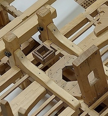
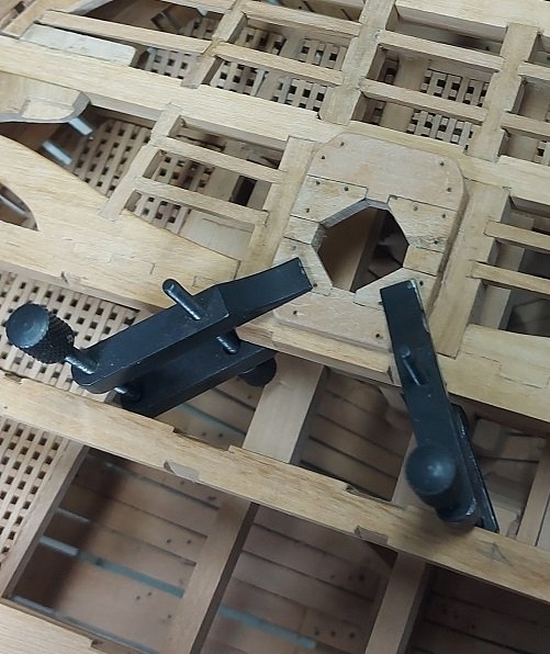
Quite a bit has happened since my last post. The lodging and hanging knees were removed as they were backwards and have since been replaced as can be seen below. The foremast partner has been remade for the third time. In the images below you can see how I built it on top of the pattern with a sheet of plastic in between so any excess glue wouldn’t stick the paper to the wood. I clamped the outside pieces down with push pins/thumb tacks and squared and clamped the end piece with a left over short square beam piece. I drilled with a #70 drill bit and added faux bolts (black monofilament fishing line roughed with sand paper to allow the glue to grip it). The topside outer edges were rounded off with sand paper and then placed on the beams. NOTE: the small square blocks (red arrows in photo below) do not belong there. The carling should be raised slightly and steps chiselled into them for the partner to rest into. The small blocks should be part of the carling but I simplified it by not raising the carling, not chiselling steps, and using this small blocks as the spacers. With the partner clamped to the deck beam using a wooden style spring clothes pin and the foremast installed, the alignment was checked by eyeballing from the stern, aligning the tallest centre counter timber through the centre of the mast and moving the partner so the mast was centred between the knight heads just beyond (at the stem post) and seen on both sides of the mast. This involved walking away and coming back to it for about 3 days. I needed it to be correct and agonised over minute adjustments… likely much more then I need to. Then I tried to devise a fool proof method to allow me to remove the partner, add glue and put it back in exactly the same location. I didn’t want to clamp wooden beams to either side as excess glue might fix them to the structure below. I tried pins but could get the darned things in! I resorted to pencil dots. Got it glued and clamped.
-
Yes I have a number of errors. 1. the partner assembly has two extra parts that need to be removed. 2. my lodging and hanging knees are reversed position and I need to tear them out. ouch! such are the experiences of a novice. I will go back and add a note to some earlier postings.
-
It seems I may have made a blunder with the foremast partner. I may have added the two outer fore-aft running pieces and they shouldn't be there. What I thought I saw on the drawing seems to actually be the carlings running between the deck beams. I'll give my head a couple shakes and look again after lunch. If I'm correct, they are easily removed.
-
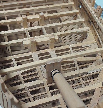
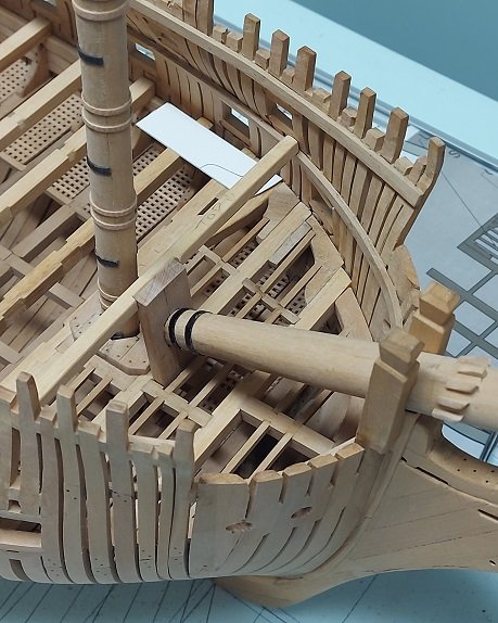
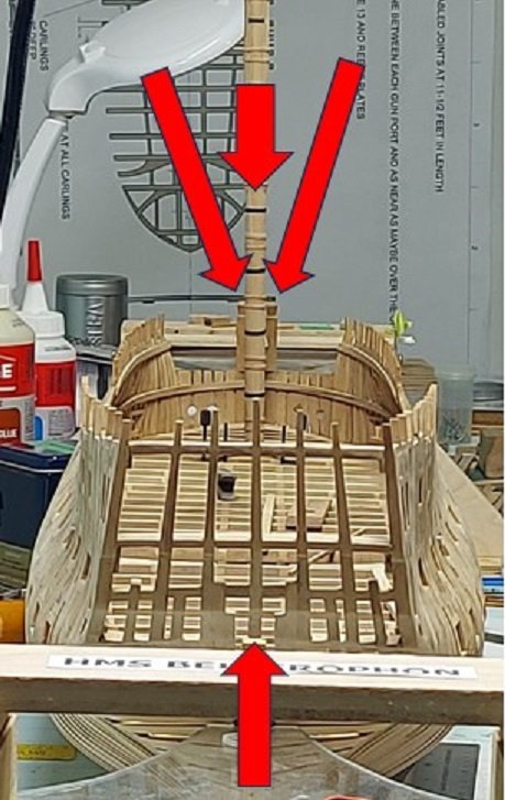
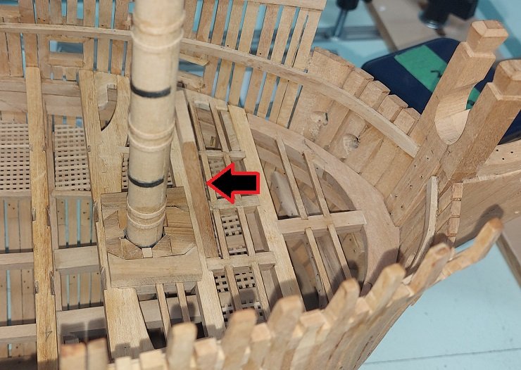
NOTE: MY PARTNER IS WRONG AND WILL BE CORRECTED AFTER POST #1711 Made the replacement partner and dry fitted it on the deck beams with the foremast installed and the bowsprit step set on the beam and its present extra length leaning on the mast. The arrow points to it as it seems to blend into the background at this angle. The step is not finished as yet. It needs some sanding and rounding off the four top outer edges. It will also rest slightly forward of where it is now but I need to make one upper deck beam to support the bowsprit step so it can be cut to length and prove the assembly location of the foremast partner. That is my next item to make. I didn't call it a mast this time! But I will ....
-
The reality is, I'm just trudging forward...
-
Thanks Tom but I owe it to the masterful drawings in TFFM volumes that I copied from. I sanded down the forward end of the partner, and after placing it and the bowsprit (mast) step I decided I could do better. By the time I do the partners on the weather decks I'll be a professional! The new stock is sanded to thickness, cut in half and rubber glued together. I'll rubber glue the templates on tomorrow and then cut the pieces out for assembly. Let's hope I don't screw it up.
-
Well, here I am!!! 😁


