
DONATION DRIVE - SUPPORT MSW - DO YOUR PART TO KEEP THIS GREAT FORUM GOING! (91 donations so far out of 49,000 members - C'mon guys!)
×


AON
-
Posts
2,868 -
Joined
-
Last visited
Content Type
Profiles
Forums
Gallery
Events
Everything posted by AON
-
 Just lovely. No other words for it. Well done! BZ
 -
The planking of the orlop deck was flush also. The short planks were set into a rabbit or notch and they were lifted out to gain access to the hold. The only areas where the long deck planks were above the beams and fastened normally like other decks were those areas with permenant cabins or walled storage areas. The grating was to allow air circulation and minimal light into the hold.
-
Good idea. Sometimes the double sided tape is difficult to clean up. Thanks!
-
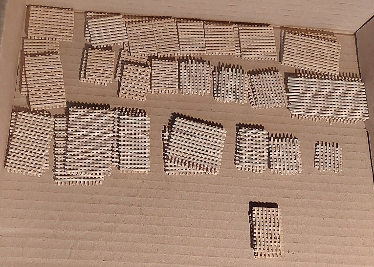
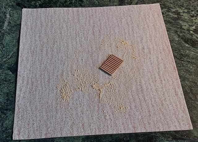
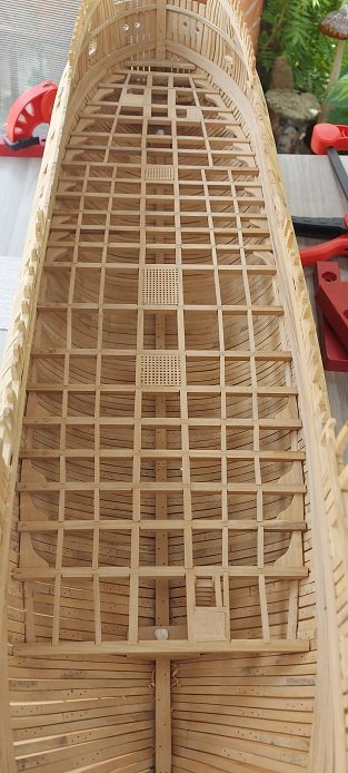
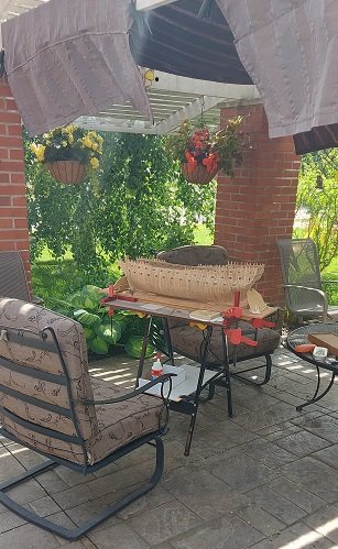
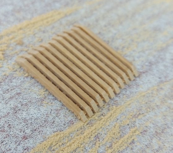
I had completed making all the Orlop deck gratings (image below). From what I could find they ran along both sides of the hull , full length, and this was called the carpenter's walk. There was also a run along the bow from port to larboard (starboard) and three central gratings. The topside of all were flush with the top of the beams. The first task was to lightly sand the top of the grating battens to be flush with the grating ledges as mine stood a bit proud. I set my sandpaper down onto the small repurposed pastry marble slab with some double sided tape to keep it secure and had at it (image below). Installing the gratings was, at first, an overwhelming challenge. The grating ledges were to be set into notches cut into the deck beams and carlings. Aligning these notches properly was impossible, and occasionally splitting the beam corners off unavoidable. To alleviate this, I simply cut (chiselled and scraped) the corner edges off of the beams and carlings that the grating ledges were to rest on, and then I sanded the underside corners of the grating ledges that were to rest on those beams and carlings (image above). Applied a little dab of white PVA glue and plopped them into place. When looking down at it you cannot tell the complete beam corner is gone, plus it will be deep enough below other decks that seeing anything will draw attention away from such a small detail. In the image above I only have the three central gratings installed. I did not install the floor, lower futtock or second futtock riders. The second futtock riders pass through the Orlop deck and up to the underside of the Gundeck clamps. In doing so, these run alongside the deck beams and pass through the gratings in those areas. That is why some beams haven't knees in between bracing them. When installing those gratings I notched them out to allow the passage of the riders. I have no intention of adding the riders... they won't be seen or missed. Once all the gratings are in I will install the Orlop standard knees above the floor beams. Then I move up to the Gundeck. I am further along than these photos suggest but still will need a couple of nice days to finish them off. Yes, I am back outside working on the ship, so nice weather is a must. Yesterday was rainy, today is a bit cruddy, and the next few are forecasted to be wet!
-
HMS VICTORY 1765 by albert - 1/48
AON replied to albert's topic in - Build logs for subjects built 1751 - 1800
I think it better for ventilation and drainage open. A model of the Bellona has it open.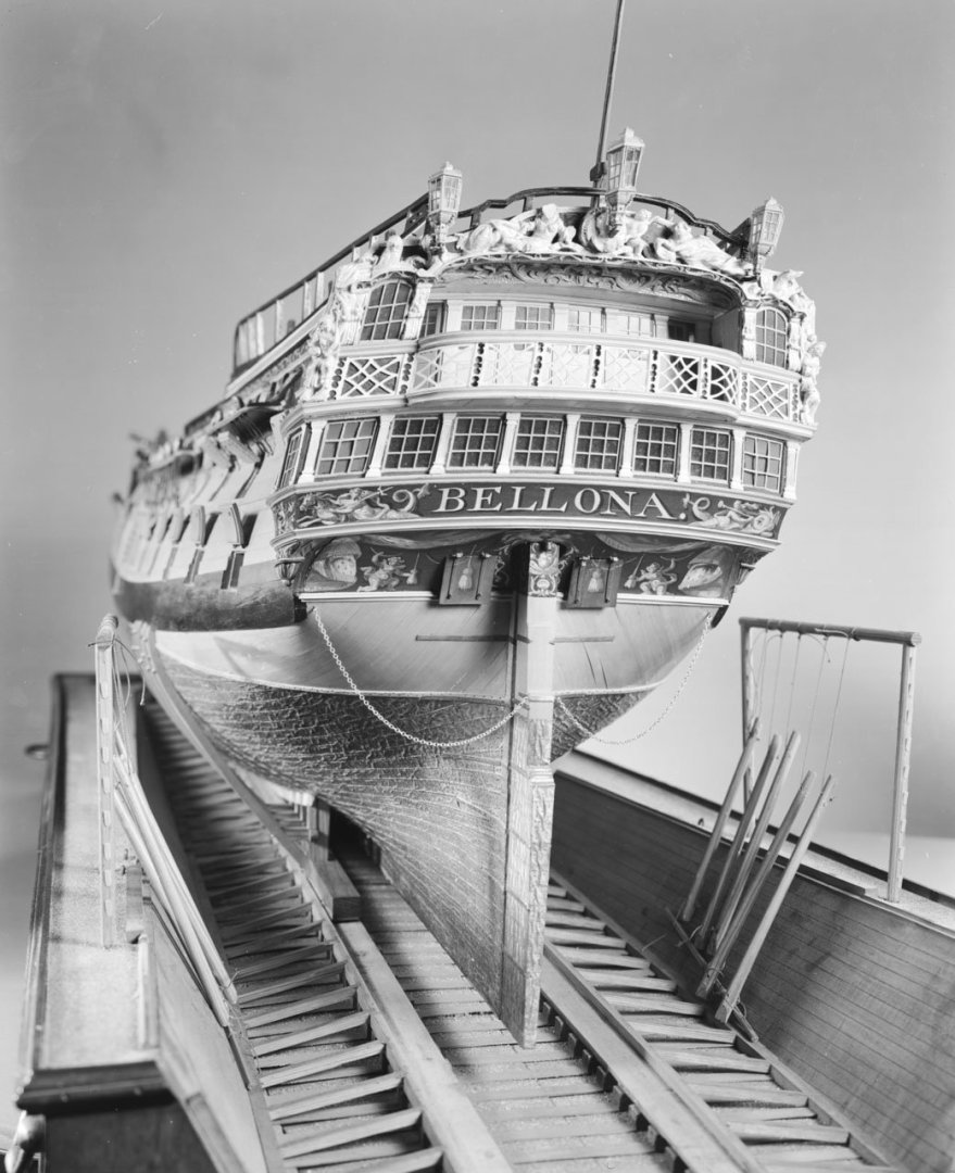
-
We would secure with a half hitch or two between tackle (two blocks or even thimbles) and may complete by wrapping the standing end around further and finish with another half hitch to hold it there, or alternatively simply coil the remainder of the standing end of the line and place it out of the way.
- 587 replies
-
- 1
-

-
- Indefatigable
- Vanguard Models
- (and 1 more)
-
do the extreme ends need to be tapered like staves on a barrel?
- 288 replies
-
- 2
-

-
- Santos Dumont No. 18
- hydroplane
- (and 1 more)
-
Good to be reminded to sometimes think outside the box. (There is more than one way to cook an egg)
- 562 replies
-
- 3
-
-

-
- vanguard models
- alert
- (and 2 more)
-
I am assuming there was some heat involved in forming the plastic tube (pressing out the sides). Is that correct.
- 562 replies
-
- 1
-
-
- vanguard models
- alert
- (and 2 more)
-
It's been a month of many things. Spring has sprung, grass cutting, readying the patio, preparing the flower and vegetable gardens for later next month. All the orlop deck stairways are installed. Made some of the standard knees but they are not installed as yet. I've got 12 of 23 gratings sets made. I won't be posting anything until I've got them all assembled and installed.
-
To bad you are so far away as our local club (MSON) has been trying to give one away along with a magnifying head set.

-
Are they for show or "to go" (R/C controlled model)? If for show, do you have any knowledge of the details or dimensions of the props? They could be easily 3D resin printed and painted.
-
What a beautiful example of rigging of a ship. If you keep up this standard she will be a master build. Well done!
- 587 replies
-
- 3
-
-
-
- Indefatigable
- Vanguard Models
- (and 1 more)
-
The camera doesn't lie. I see no blemishes at all. Well done! When will you be scheduling classes?
- 562 replies
-
- 5
-
-
-
- vanguard models
- alert
- (and 2 more)
-
On the other hand... I imagine they used what they had. If you didn't have a fiddle block of the appropriate size you "McGyvered" one of your own!
- 587 replies
-
- 2
-
-
- Indefatigable
- Vanguard Models
- (and 1 more)
-
Just wondering... I wonder why a set of blocks nested end to end was used as opposed to a fiddle block? ...not expecting an answer, unless someone knows!
- 587 replies
-
- 2
-
-
- Indefatigable
- Vanguard Models
- (and 1 more)
-
First let me say I haven't done a miniature eye splice (yet) and I am impressed with anyone that manages it so well. With full size rope, I find that gripping it either side of where the eye splice will be, twisting to unravel the strands and pushing both hands together will open the strands to get a spike or fid into and hold it. I imagine with small scale rope (1:64) the same will likely be true, the needle being your fid or spike, though a third hand might be useful. This might make it easier to make sure you don't pass a strand through a strand. When the splice is done I would put it on the floor, step on it with my shoe, and roll it back an forth under my body weight to tighten it up. I imagine rolling the scaled down version between a pinched thumb and finger would do the same thing. One day I will have to try this all for myself.
- 562 replies
-
- 3
-
-
- vanguard models
- alert
- (and 2 more)
-
Great job. Looks amazing! BZ How many fingers were sacrificed?
-
you certainly made that look easy.
-
Period Scale Model Masting and Rigging Tables
AON replied to DaveBaxt's topic in Masting, rigging and sails
I honestly do not know. How quickly did people receive the information and actually implement it?

