
HOLIDAY DONATION DRIVE - SUPPORT MSW - DO YOUR PART TO KEEP THIS GREAT FORUM GOING! (78 donations so far out of 49,000 members - C'mon guys!)
×


AON
-
Posts
2,863 -
Joined
-
Last visited
Content Type
Profiles
Forums
Gallery
Events
Everything posted by AON
-
 What an interesting use of electrical wiring heat shrink tubing! Now that is thinking outside the box.
- 288 replies
-
- 3
-

-

-
- Santos Dumont No. 18
- hydroplane
- (and 1 more)
-
I had bought my pin vises (2) and number drill bits from McMaster-Carr. I bought two pin vices because they came with a reversible chuck (larger shaft/small shaft) so I could have one set for each. That ended up being a waste of money as they are easily reversed. I bought a few bits that came in multiple quantities in envelops. The smallest of which are quite delicate and snap with the slightest side pressure (flex) if you do not choke up on them with the pin vise chuck.
-
I wonder how more experienced modelers manage the task?
-
Yes. I took the subassemly to my belt sander and gradually created the taper from point to point, each side.
-
I drew an imaginary line from B to D and from A to the Gripe horizontally opposite D and tapered the stem to these points along these lines. It made sense to me.
-
THE CABINS LOOK GREAT! I just watch a two short videos of the cori robotic knee replacement surgery... got my GDD (Google Doctor's degree!). I'm guessing it will be a quicker recovery with this procedure. Hoping all goes well and your back jogging in no time.
-
Sometimes I find the small restricted area fiddles with my mind to make it more difficult than it should be. I also find carving on end grain to be difficult. I find that if I take a slightly larger piece of thin stock and rubber glue that to a base piece of wood that is clamped, then pencil mark the shape, then start carving it is somewhat easier. Then I remove it from the base and take it to the table top disk sander and sand the edges to their margin lines.... but still the first one can take three attempts! But it gets easier.
-
I get to 9:51 in the above video and it kicks me back to the beginning! I can pick just ahead of that and it loads and plays... not sure what I missed, assuming not much
-
How do you know?
-
HMS ANSON 1781 by albert - 1/48 - 64 guns
AON replied to albert's topic in - Build logs for subjects built 1751 - 1800
There is nothing more satisfying than getting the last of those seemingly never ending frames done! BZ -
Thank you Bruce. I find the mention of those in 1790's and earlier quite interesting
-
Well, that was a better idea then what I was trying to do originally. I'm too embarrassed to tell you. 🤐
-
Was it the actual removal of the rubber cement or the paper template? If it was the rubber, what did you use? I use a crepe eraser to remove rubber cement residue. Thanks to David Antscherl who had taught me this. You can buy it at any tool shop that sells sand paper. It comes in a block and is used to clean the sand paper to get more life from them. I cut about a 1" slice off one end to use as my rubber cement residue eraser. Works like a charm!
.thumb.jpg.4267f044b2b4ccd791ffb52039777240.jpg)
-
Thank you Druxey. I printed them all out to help me compare and fully visualise the impact. The revised spacing blends in nicely... it is not noticeable as any type of rework You have a good eye for this, and so I suspect you must have some experience, eh? 🙃
-
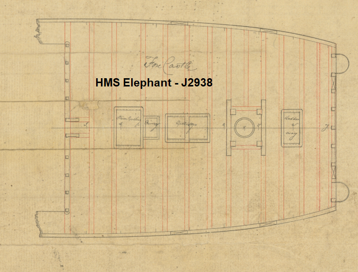
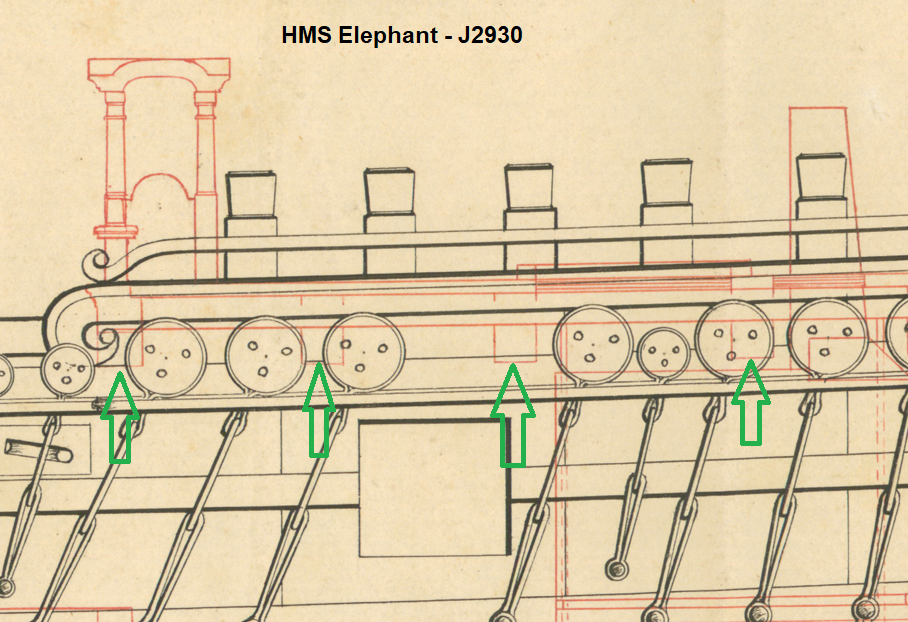
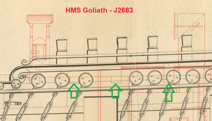
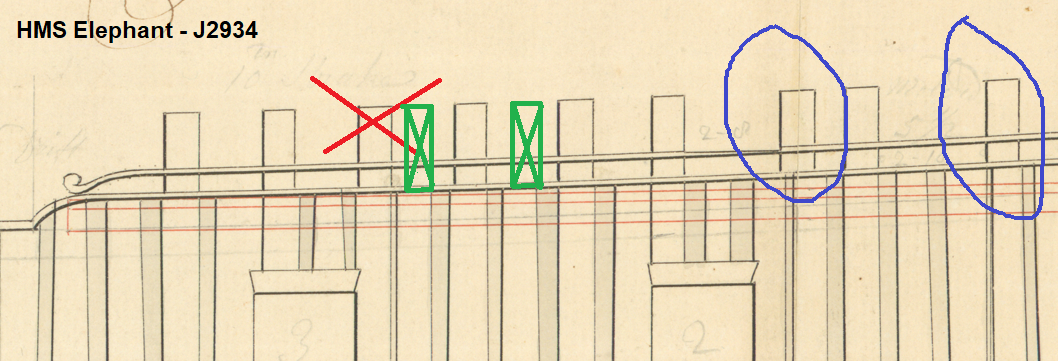
Good morning Druxey. You can see in the images below for HMS Elephant and HMS Goliath that removal of the third timberhead from the left offers a wider opening location clear of the shrouds and there is a deck beam in that location that would be similarly located to the original two gun port locations which can be seen on the Elephant deck plan. If the third timberhead from the left was cut down, would they have had install a short timberhead (as can be seen at the far right in framing drawing J2934) between the third and fourth or the fourth and fifth? I'm guessing between the third and fourth (move the original over one to the right) as it is behind a deadeye and should clear all rigging and doesn't seem out of place.
-
Druxey Then modifications must have had been made to accommodate the extra two carronades on the forecastle. I presume this means cutting out a timberhead? I would hazard a guess - the one forward of the green arrow.
-
This is what I understand the classes to be and include Third rates of 74 guns (two-deckers) Bellona class (Slade) Bellona 74 (1760) – broken up 1814 Dragon 74 (1760) – sold 1784 Superb 74 (1760) – wrecked 1783 Kent 74 (1762) – sold 1784 Defence 74 (1763) – wrecked 1811 Third rates of 74 guns (two-deckers) Arrogant class (Slade) – modified Bellona class Arrogant 74 (1761) – broken up 1810 Cornwall 74 (1761) – scuttled/burnt 1780 Edgar 74 (1779) – broken up 1835 Goliath 74 (1781) – razéed to 58 guns 1813, broken up 1815 Zealous 74 (1785) – broken up 1816 Audacious 74 (1785) – broken up 1815 Elephant 74 (1786) – razéed to 58 guns 1818, broken up 1830 Bellerophon 74 (1786) – sold 1836 Saturn 74 (1786) – razéed to 58 guns 1813, broken up 1868 Vanguard 74 (1787) – broken up 1821 Excellent 74 (1787) – razéed to 58 guns 1820, broken up 1835 Illustrious 74 (1789) – wrecked 1795 Fourth rates of 60 guns (two-deckers) Edgar class (Slade) Edgar 60/64 (1758) – scuttled 1774 Panther 60 (1758) – broken up 1813 Firm 60 (1759) – sold 1791
-
So then, my Bellerophon. Yes, the two red arrows are the 9 pdrs. Where was the carronade installed that the Admiral said was also there? I say at the green arrow. Would you agree it is the only logical location?
-
It is a well worn path we've all walked... and some still are ( like myself). As George Bernard Shaw said: A life spent making mistakes is not only more honorable but more useful than a life spent doing nothing. Keeping moving forward. You will get better at every challenge.
- 71 replies
-
- 4
-
-
- Miss Adventure
- Model Shipways
- (and 2 more)
-
Chapman: I thought both Vanguard and Edgar were Arrogant class ships. Druxey: You've also confused me. Are you addressing PQLear who reopened this thread with a question about Vanguard at the Battle of the Nile where Brian Lavery wrote she had 4 carronades and 2 long guns on the forecastle, or are you addressing me and my Bellerophon where an eyewitness, the son of the ship's gunner who both signed on with the first crew claimed she had 2 carronades and 4 x 9 pdrs on the forecastle?
-
Check RMG for armada class 74's and 9 drawings popped up with only 3 having images and these showed forcastle gun ports far forward. Checked Harold Underhill's drawings of a 74 dated 1813 and the gunports from sheet to sheet do not seem to agree or relate to each other but the one deck plan does seem to agree with my arrows above.
-
Carronades on the rear red and green for the Vanguard. The Bellerophon was arranged differently with only two carronades on the forecastle.

.jpg.523a3e819db2a4d47f7cc2551a0de041.jpg)