
HOLIDAY DONATION DRIVE - SUPPORT MSW - DO YOUR PART TO KEEP THIS GREAT FORUM GOING! (83 donations so far out of 49,000 members - C'mon guys!)
×


AON
-
Posts
2,865 -
Joined
-
Last visited
Content Type
Profiles
Forums
Gallery
Events
Everything posted by AON
-
 I've not used it but it gives it a finished "painted" look. I prefer a natural wood look and I like it when details stand out!
- 968 replies
-
- 1
-

-
- hahn
- oliver cromwell
- (and 1 more)
-
I managed all but the last one piece, the roundhouse port side clamp. Not enough clamps to hold it with glue. Tomorrow is another day. Now for something different... A fellow club member printed some scale 1:64 crew members for my build. Amongst them was a surprise! Two fiddlers seated cross legged. If you look closely the fellow on the right is wearing glasses and looks quite a bit like yours truly. Yup, it is me! So I can put myself in my build. He also printed a larger version at 1:25 ...and at sometime while in my care the end of the bow to the left of the violin strings snapped off. So I carefully removed the rest of it and gingerly removed the frog from between the fingers and thumb with a fine mini chisel while wearing my magnifier. Then I made a new bow from Pau Marfim, stained and varnished. Added hairs from my old drafting brush and slipped it into place. I cut one to simulate a broken hair. It looks a bit too chunky so I'll thin out the stick tomorrow. I had tried to personalise it with hair from ma tête, but it was a bit too unruly... wouldn't be tamed into place.
.jpg.d101af86dbf9dc225e813edcc93dff3e.jpg)
.jpg.39a7ca1bd45389d065468a205c9f2818.jpg)
.jpg.b099b597c7572bdafc3557ae6baf50d5.jpg)
-
I've seen them carved individually and glued to a curved stern base plate. Carving such small pieces is quite a talent... but only impossible if you don't try and try again. My figurehead took multiple attempts until I got something I could live with. BTW, I took your sketch of the stern works, scaled it down to 1:64 and held it against my Bellerophon. Almost a perfect fit! I'm certain the ever so slight mismatch is my fault.
-
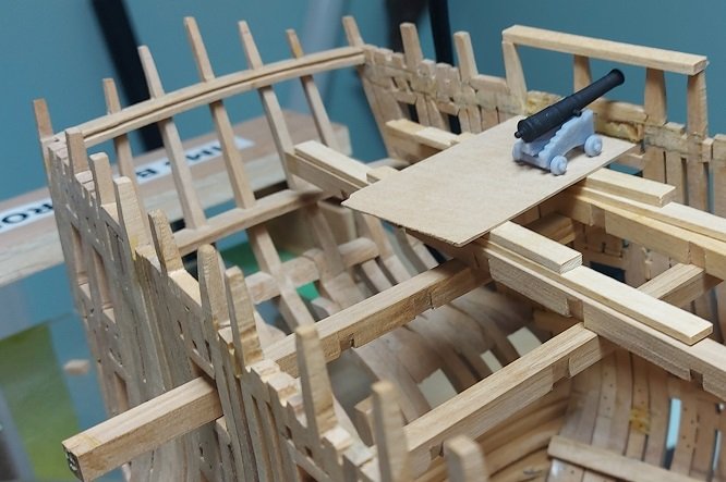
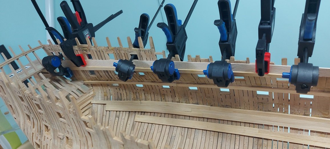
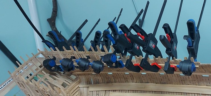
Slowly getting my deck clamps in after a few more health concerns (all better presently). Working on the quarter deck/waist/forecastle clamps that support the deck beams. My first photo is locating the deck height using my gun carriage assembly to get it to look correct. The height of the deck is measured using the device I made to originally mark my heights (but I marked the top of the beam instead of the bottom!). Then comes the math... using the contract to get the deck plank thickness and deck beam height and subtracting these from the height measured. That locates the height of the top of my clamp. This I double check to the plan measurements.... close enough! Now I calculate the difference to the height of the top of the lower cill of the gun port. This is the width (height) of the spacer needed. Next I made my spacer, thin flexible maple, and clamped it to the hull (red nosed clamps), locating the top edge to the top of the gun port lower cill. My deck clamp was glued and clamped (blue nosed clamps) while butted up against the spacer. You can see the other deck clamps below. I've got two more sections to install per side at this level, the last piece needs to be steamed to fit at the bow. Then is the roundhouse or poop deck clamps and then I can start putting the decks back in. Photo below... you can never have enough clamps.
-
Leon by Doug McKenzie - 1:300 - BOTTLE
AON replied to Doug McKenzie's topic in - Build logs for subjects built 1851 - 1900
Good morning Doug. I find what you are doing extremely fascinating. Is this your first ship in a bottle? I've never done one myself, but it is an itch that might need scratching some day soon. I've acquired a copy of How To Build Historical Bottled Ships by Bill Lucas (1982) for when that time comes. So I follow to see it done. Thank you for posting this. I also enjoyed your posting the 1:8 scale model photo! -
Seems correct as you can see the light below reach up to the upper beam.
-
upon reflection it seems the headroom is needed on centre below this deck, in the hold. the higher line seems like the wings (officer's quarters) hopefully someone with more experience can confirm.
-
Possibly it is reversed? The lower section is on centre for more clearance passing through and the raised levels are the officers cabins? They'd step up into them. I admit it is all unexpected. I am just guessing. Waiting for someone "in the know" to enlighten us both!
-
You only had to measure it three times to be confident it was correct before you started potentially butchering the whole thing. I am impressed!
-
You've got steadier hands than I! I don't think I could have masked that adequately.
-
I wonder how they would look after sitting around untouched for a month or more?
-
I am interested in the answer too!
-
That's what I was thinking... it looks quite smart and tiddley (finished) with the batten!
- 332 replies
-
- 2
-
-
- Harpy
- Vanguard Models
- (and 1 more)
-
A few drop planks would fill that nicely. As it will be right side up who will notice.
- 71 replies
-
- 1
-
-
- Miss Adventure
- Model Shipways
- (and 2 more)
-
The words that come to mind are using drop planks and stealers but I do not see a need for them yet in your photos above. Take a look at post #34 at: https://modelshipworld.com/topic/37626-hms-harpy-1796-by-blue-ensign-–-vanguard-models-164-scale/page/2/#comment-1081778 You will see some quite good examples of drop planks and stealers if you should need to use them. Have you tried steaming or soaking your plank in hot water then clamping them to dry to shape before installing permanently?
- 71 replies
-
- 1
-
-
- Miss Adventure
- Model Shipways
- (and 2 more)
-
Good morning Dave and welcome to MSW. As a newbie to the hobby you might consider joining a local club. If you haven't one near you on your side of the river you might consider one nearby on the other side. Check us out at: https://www.mson.ca/ We are having our February meeting this afternoon at 1:30 PM ET and they run about 2 hours.... well before the football game today. You can attend via zoom. Email us from the email address on the web page and I will send you the zoom link.
-
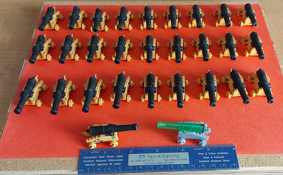
I completed the assembly of all 28 of the gun deck 32 Pdrs. After some encouragement from one of our club (MSON) members I again attempted to dry rub the barrels to try and make the details more visible as they were lost in the flat black. You can see the results in the close up... the one that shows the dust! The raised details (reinforcing rings, powder pan, royal cypher) are not very high at near 0.01" so I found it difficult to try and apply the dry rub to only the raised parts. So I gave up on focusing on that and focused on the results which in essence mutes the flat black and shows the detail as compared to the image in post 1741 above. I added the wooden quoin handles. They are made from Pau Marfim cut and sanded down to 0.06" square strips, one end sharpened to a point and then pulled through the two largest holes on the draw plate to round them to 0.057". The end of each handle was sanded round prior to cutting them off of the strip to then glue them into the drilled hole in the quoin. Now I go back to re-installing my orlop and gun decks.
-
what is the flanged hole under the support just to the right of the centre of the last photo?
-
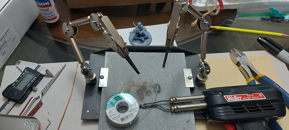
The photo below is my setup for soft soldering two breech rings at a time. The soldering station was purchased from https://gesswein.ca/products/grs-soldering-station They were considerably less expensive when I got mine! It is meant for silver soldering, but I normally use it when using my butane torch and copper-phosphorus wire solder. This solder allows me to blacken the copper wire and solder joint with LOS (Liver of Sulphur). The 60/40 soft solder I used on the thin gauge copper wire here (0.5 mm = 0.02" dia) will not blacken with LOS so I used a black permanent marker as I've seen done by other modellers in our local club.
-
I also have a copy of the tables by Edwin Newell Rich from NRG spring 1962 issue 12-1
-
I have a copy of the table Tackle + Breeching scantlings The Sea-gunner's Vade-mecum Being a New Introduction to Practical Gunnery by Robert Simmons, 1812 It would be interesting to compare this to your table. Would please you send me a copy.
-
For those interested ... The 0.5 mm (0.02") diameter copper wire was from Billings Boats: P/N 04-BF-022A The package has two coils but they do not state the length. I emailed them and they told me each coil is 250 cm (98.4"/coil)... so I can now figure out how much more I might need to complete 74 guns. The formula for sizing the eye bolt and breech rope ring wire size and the breech ring diameter was found in the NRJ Publication 36-2, page 100: Sizing Gun-Tackle and Breeching Eyebolts and Rings - Published by I.R.Butts (Boston, 1858) It states that to calculate the size of wire for carriage gun-tackle eye bolts and breeching rope rings, "multiply the diameter of shot by 0.2, the answer is the diameter in 8ths". It also states that the breech ring inner diameter is "to be in the clear of the diameter of the shot". I found a table that stated the inside diameter of the eye (the loop) was in essence clear of the diameter of the wire: 32Pdr @ 1.83" inner diameter = 0.028" at 1:64
-
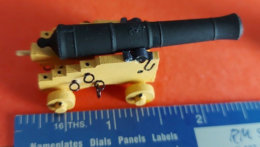
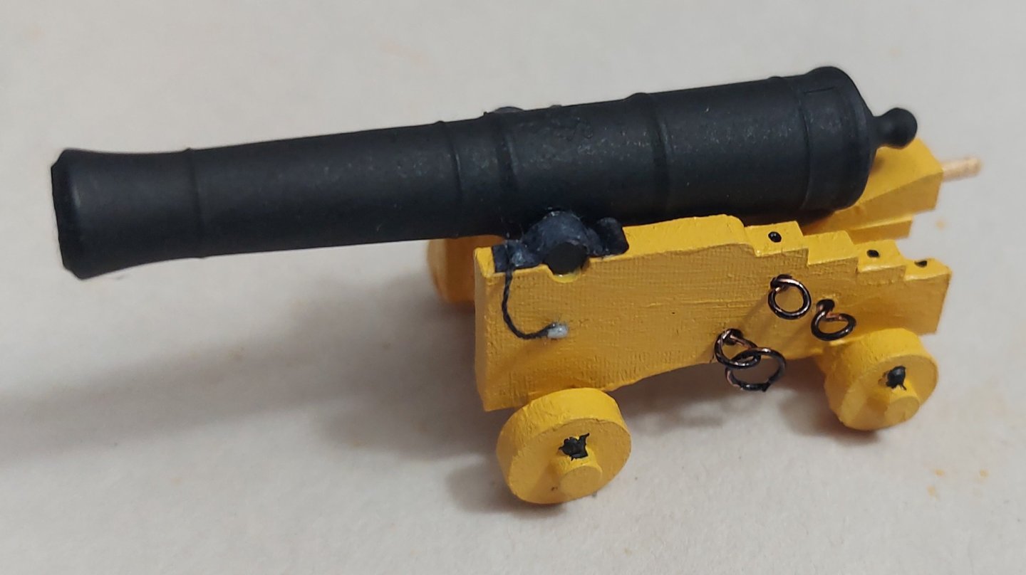
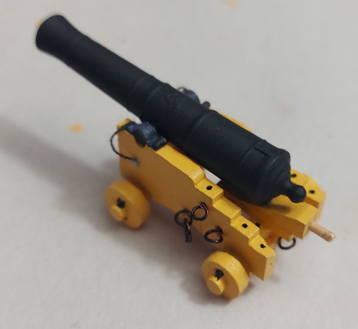
Completed the painting of all 28 x 32 Pdr carriages and the assembly of one. Carriage painting was done with brushes. Three coats of yellow ochre and then spots with black. Could have used younger, steadier hands for the fine black touch ups... but it look fine from 12" away. The camera hides nothing! The cannon was spray painted with acrylic flat black some time ago, multiple coats. I tried highlighting the reinforcing rings and royal cypher with a smokey grey but it made a mess as it is all so tiny. The cap square is card stock blackened with a permanent marker. The one end is curled over itself. The cap square chain is simply black sewing thread. I tried a finger knitted chain stitch, which look quite good until set up to the carriage and it was about 3X too large for the scale. The eye bolts and breech ring are made with 0.02" (5mm) copper wire, the proper scale. The breech rope ID (0.1") is correct but the eye loop (0.06") is larger than it should be as this was the size I was comfortable with. Eye bolts were twisted over a 14 AWG copper wire (0.06" dia) ... I do not have a 1/16" drill bit to use for this. The breech ring was coiled over a 7/64th drill bit, multiple wraps and then cut with hobby snips to produce multiple coils at once. They were soft soldered 60/40 (% tin/lead) solder. The eye loops and rings were blackened with a permanent marker. I used Weldbond, water based PVA glue to assemble all the parts. It dries crystal clear. The quoin handle was made from a small diameter maple dowel, sanded down while mounted on the drill press and then pulled through a draw plate. All holes in the carriage were pilot holes and needed to be opened up for the twisted wire eye bolt stubs and quoin handle. Presently, I have all the breech rope rings (54 ea) made and soldered. Going to start on the (189 ea) eye bolts next.
-
Do you stack the spacers to get the variety of thickness in 0.25mm increments?
-
Good evening Bruce. I just watched the NRG video of your presentation last Saturday... Well Done! I am sorry I missed sitting in on it but I had an unexpected early morning appointment elsewhere that kept me away. Alan


