HOLIDAY DONATION DRIVE - SUPPORT MSW - DO YOUR PART TO KEEP THIS GREAT FORUM GOING!
×


AON
-
Posts
2,856 -
Joined
-
Last visited
Content Type
Profiles
Forums
Gallery
Events
Everything posted by AON
-
 Yellow Ochre. Happy New Year!
 -
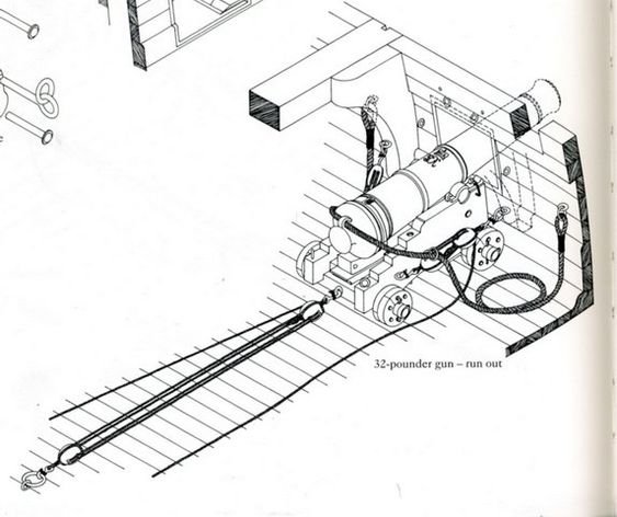
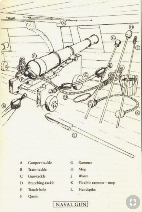
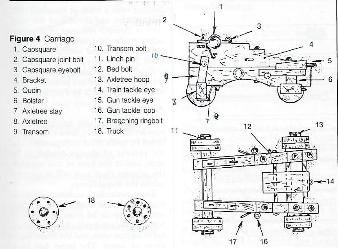
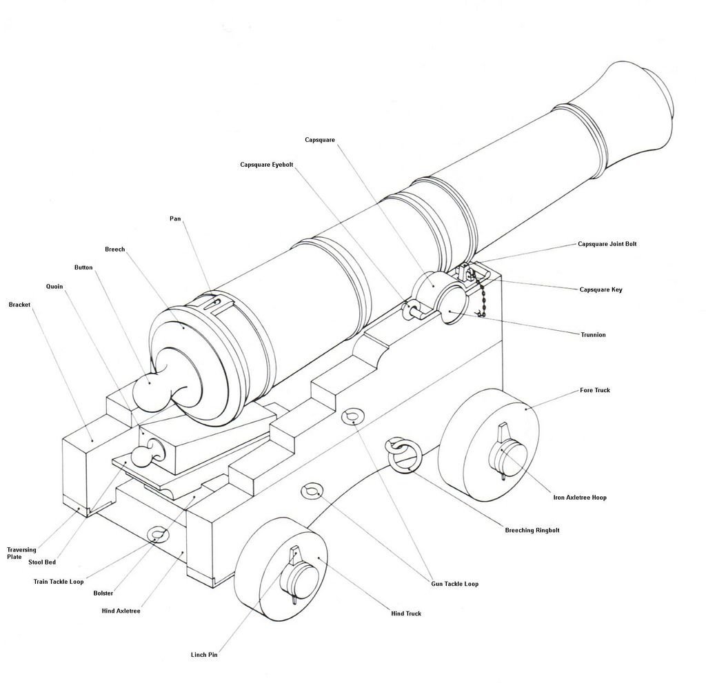
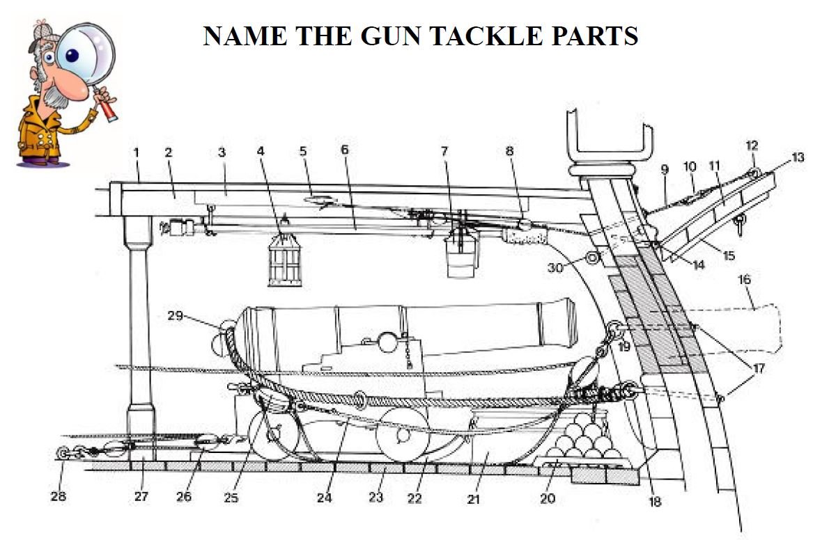
This one is a mish-mash. On both sides the breech rope is well to the outside eyebolts where as the gun tackle is in on the right side and out on the left side. Also they eyebolt location of the breech rope and guntackle are switch as other sources suggest the breech rope secures to the lower eyebolts. Two securing eyebolts above the gun port.
-
In this image the eyebolts are both lower than the lower gun port cill
-
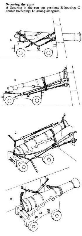
Below is an image reference to various methods of securing the guns. In all images only two eye bolts are shown to either side of the gun port, not three. Interestingly, both are quite high, adjacent to the actual gun port, none lower than the lower cill which some other references would suggest. In image "c" there is a single eyebolt above the port... but in the earlier photo I can see two eyebolts. It is all very confusing.
-
I'm not quite back yet. I had surgery; had been waiting sometime for a date and grabbed it when one was offered. Still recovering but feeling much better. Might be a few more weeks before I get in the shop. Hmmmm...might be a good time to paint my gun carriages!
-
I find cleaning the blades (soapy water and a scrub brush) regularly to remove dirt and sap usually resolves the issue. If not then the teeth likely need resharpening. Never experienced a misaligned blade.
-
Close? Possibly the adjacent gun used the extra ring at this station. Would that be far enough? I wonder if anyone on the forum knows?
-
one more view
-
Thank you for asking and making me look again. I have a folder of pics taken by a friend and darned if it wasn't much clearer! There are extra bolts. I didn't see these in the video.
-
I wonder if 3 and 4 are actually the adjacent gun eye bolts being used to train the gun? I do not see extra eyebolts on the Victory
-
I can see your confusion as I too have gun rigging sketch references that show two different things. I always try to find a believable source. Looking at videos of HMS Victory that can be found on line I see the ring bolts are one over the other in areas 1 and 2 of your marked up sketch.
-
I was told to laminate tight bends with multiple thin strips. Make the pieces wider because they will wander. Steam and bend them as an assembly without glue. Allow for spring back. When dry, glue them together and clamp. When cured, sand the edges to proper width then assemble on the model.
-
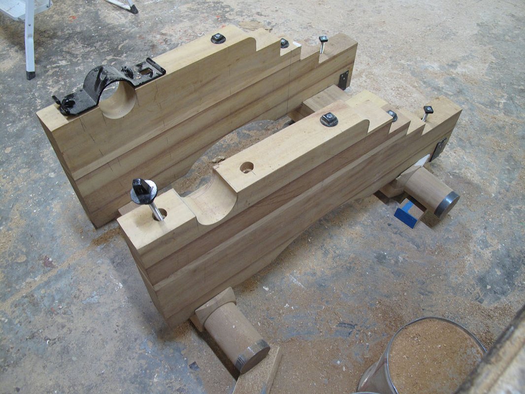
Glen Unless my eyes decieve me, your 22130 gun carriage plan pdf is odd. The top sheet, top left corner, top view of the carriage. The top bracket has steps square to the centerline and the bottom bracket has steps square to the bracket. I wonder why they depicted them both ways. Alan
-
I offer the two images below showing the end face of the steps were square to the bracket and not to the centerline of the carriage assembly. On the Victory photo, the end face of the step would not be seen if it was square to the centerline, so it must be square to the bracket face. the carriage construction photo... square to the bracket face. I suspect the carriage drawings were simply easier to complete square to the centerline with a tee square... but easier to cut square to the bracket face. They would have enough of a necessary challenge cutting the cannon pivot trunnion and the axle pockets square to the centerline so why make things more difficult then they need be. ?????
-
hopefully these help
-
In my mind there was one communal discharge point and multiple levels plumbed into each other. I also think the hinged seat was to allow scubbing the bowl clean by the Stewart of the gallery (I made up the title).
-
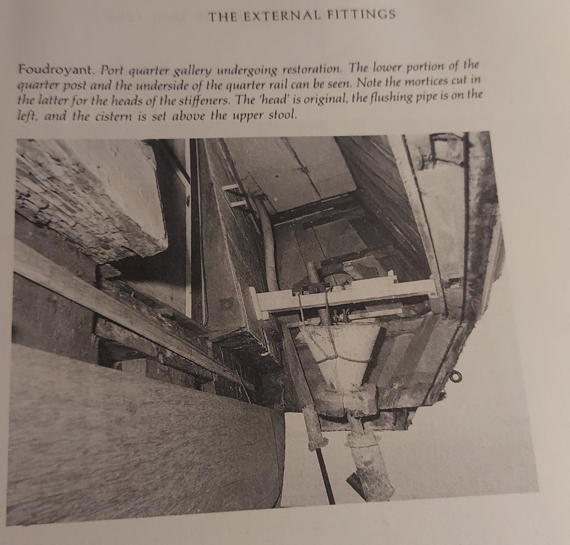
I am reading in Those Vulgar Tubes ( by Joe J. Simmons III) that when two or three levels were involved the seats were offset and by the late 1700's they had a flushing mechanism utilizing a water tub located on top of the quarter gallery. They do not describe or show how the soil tubes were run or located. Goodwin's Sailing Man of War, pg 199 has a photograph of the Foudroyant port quarter under gallery restoration and you can see the "flushing pipe" and "cistern" but doesn't seem to discuss it at all in the text on pgs 199-203.
-
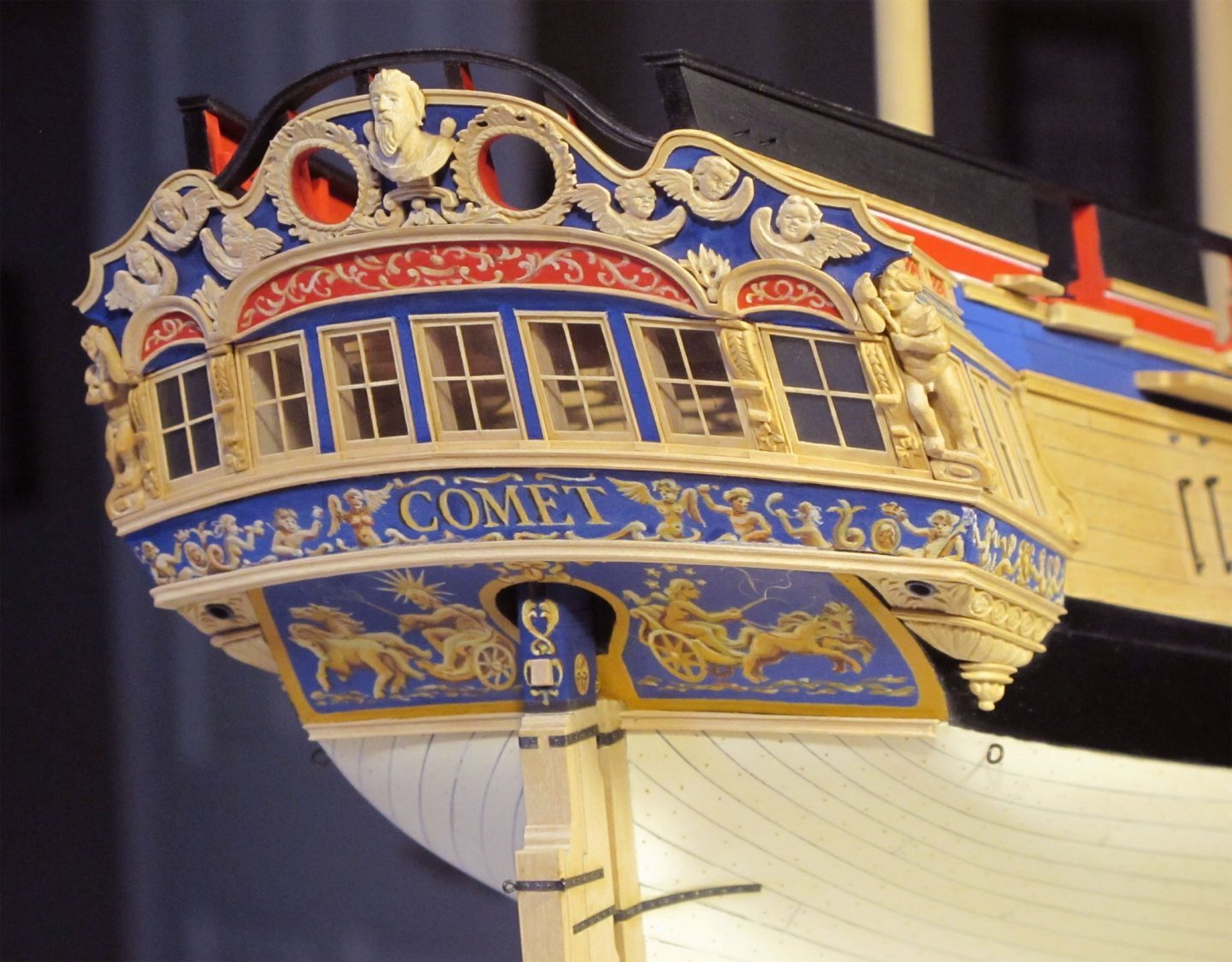
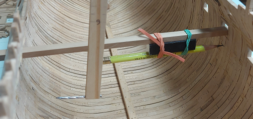
The model is getting more difficult! Below is a pic of the soil pipe discharge from the quarter gallery that David Antscherl included in his model of the HMS Comet I note it is a direct run and not to the dangling ornament. How was it plumbed for a two or three decker? I'll keep looking.

-
Darn auto correct on my phone. Not incline .... in line. Apparently age has tripped me up again. I am wrong. They are inline. Apologies
-
I thought they weren't. Also, I believe the fore and aft trucks (wheels) should not be inclined. The fore trucks are inboard.
-
Excellant work! I believe the officers seats of ease had a discharge tube connection running down to the pointy ornate bit on the underside of the quarter gallery Dumping directly into the water. I remember reading about gawkers getting too close to the Bellerophon When Napoleon was held onboard and getting a surprise.
-
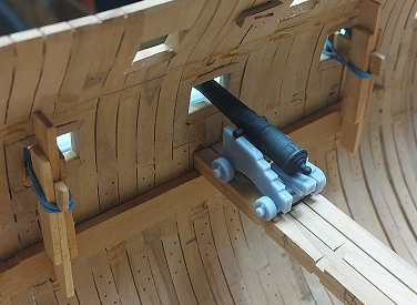
I would prefer to learn from someone else's mistakes except I just don't seem to remember them as well as those I make myself. Since I told one person (and the cat is out of the bag), I have gotten past my damaged pride and so can tell everyone. I got to a point where I could actually put a gun on the gun beam and see it poke through the gun port. The problem was it didn't. The deck was too high. (note the past tense) I double checked my scale on the 3D gun models and compared to the 3D printed guns. Perfect. I double checked the dimensions of the model to the reference material dimensions. Perfect. I checked the height of the deck.... and there it was. I had measured from the underside of the keel to the top of the deck beam, not the underside. This made my clamp location too high, hence the deck being too high. I tore out the gun deck, and since lowering the gun deck makes the gap to the orlop deck too small... I tore it out also. Sanded everything yesterday and recalculated and proved the new deck height today. Orlop and gun deck clamps going back in today, then I get a "do over". Up side: I guess I am not a novice in this area of the build anymore so my results should be more pleasing to the eye. Now I am away until after my "new" anchor cable riding bitts are installed.

-
Some bad news. I will not be posting for some time. Something happened and I would not like to talk about it at this time. I will be back (just like a bad penny), but it will be quite some time. Sorry folks.
-
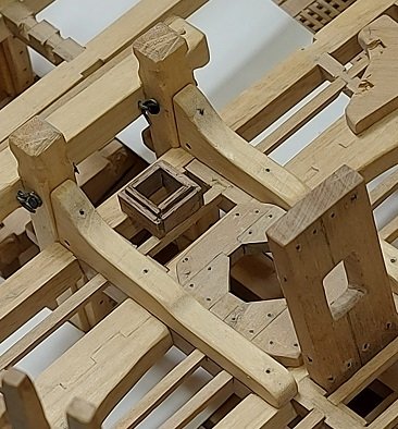
Anchor riding bitts and small scuttles are done. Now I must decide : do I go forward and work on the hawse hole inboard side, or do I continue aft and work on the stairway to the orlop deck?

-
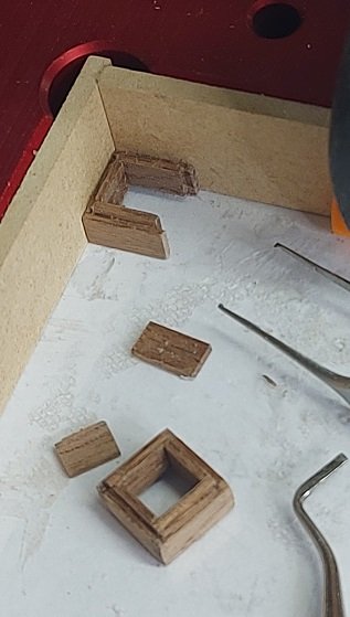
Made the two scuttle coamings. Used walnut for contrast as I wanted them to stand out amongst all the other wooden pieces. Went square shaped at an unconventional 27" because the size looks good and I shifted my ledger beam over about half a thickness. Forward one installed.