
HOLIDAY DONATION DRIVE - SUPPORT MSW - DO YOUR PART TO KEEP THIS GREAT FORUM GOING! (78 donations so far out of 49,000 members - C'mon guys!)
×


AON
-
Posts
2,863 -
Joined
-
Last visited
Content Type
Profiles
Forums
Gallery
Events
Everything posted by AON
-
 Just attended a Zoom meeting with the Society of Model Shipwrights (UK) this afternoon and an image of the forcastle of HMS Indefatigable filled my screen showing six guns. The two forward most were cannons and the four aft were carronades. What was of most interest was that the four forward were where guns should have been (red arrows) and the aft most gun was located one step aft from my green arrow in the image below. If a carronade were put on a 74 gun ship in that location it would blow out the rigging... the green arrow location misses the rigging but the rail needs to be cut out similar to the other locations. Problem solved!
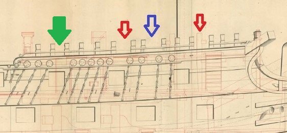
-
Yes. I corrected it just now.
-
I have been steaming or soaking in boiling water then clamping in place with shims for a slight over bend to allow for spring back. Once dried overnight I glue with wood glue and clamp until set.
- 47 replies
-
- 2
-

-
- La Nina
- Artesania Latina
- (and 1 more)
-
Chapman: Yes, I have that book also, but it doesn't have any detailed info on guns whereas the other does. Walter: Interesting. The forward position has less clearance aft of the gun, so I thought if it did replace a gun it might have gone there. Unfortunately the boy (then man) who was there at the time said all carronades were extra to the full 74 guns. I continue to try to find an image (painting or sketch) that might provide a clue, or better yet, written description to remove all doubt.
-
Lieste, I asked my question earlier and have copied below for two reasons: 1) there seems no place to add two carronades or "smashers" on the forecastle unless modifications are made, and 2) Rear Admiral Sir John Hindmarsh, Kt., R.N. who served on the Bellerophon as a "boy" and then midshipman while his father was the gunner (warrant officer), said the carronades were extra to the 74 guns and these extra carronades included six on the roundhouse and two on the forecastle. Source: Page 13 of From Powder Monkey to Governor by F. Stewart Hindmarsh, Access Press, 1995. ISBN 0 949795 88 7 So I ask again, which two guns on the forecastle were removed to be replaced with carronades and could you please quote the source, as I would like to add this information to my research. Thank you. Alan Were the the two forward or the two aft on the forecastle replaced?
-
Were the the two forward or the two aft on the forecastle replaced?
-
From my research/understanding for my build (HMS Bellerophon), they normally did not count carronades as "guns"... they were "extra" unless maybe they replaced the normal compliment of guns (?) which were said to be 28 each x 32 pdrs on the gundeck, 28 each x 18 Pdrs on the upper deck, 14 each x short 9 pdrs on the quarter deck and 4 each x long 9 Pdrs on the forecastle. Bellerophon was said to have had 2 each x 32 pdr carronades on the forecastle and 6 each x 18 pdr carronades on the Roundhouse (poopdeck). There was an AO 1779-07-16 establishing carronades of 18 and 12 pdr for all classes of ships, relaxed by the end of 1779 and by 1780, the actual fitting of authorised carronades was left to the discretion of the captain, to avoid unwanted disruption on the command deck, or interference with the rigging. By 1780-03-09 carronades fitted by application of the captain. Politics caused the ordnance board to recommend against carronades, the Admiralty dragging it's heels over forwarding this "finding" to the Navy board until several months after the report date (1780-10-21, forwarded 1780-12-15) Early evidence of the utility of the carronade in close action suggested that there was a use for them, and more experimentation was authorised as well as the optional use of carronades at the captain's request (including some fully carronade armed ships)... 1781-12-28, the Navy board recommended two 68 pdr carronades for those capable of supporting them, and 42 or 32 pdr carronades be allowed for smaller rates at the request of their captains. From 1794-11-24, a new carronade establishment replaced the earlier 1779 one, with a 74 being authorised 2 x 32 pdr and 6 x 18 pdr in this establishment. From 1798-03 (March) every line of battle ship was fitted to receive carronades on the fc/qtr deck. The Battle of the Nile was 1-3 August 1798.
-
I'll admit that I've got my fair share of badges of honour! Most decks had a rise to them. The mid width (over the keel) being higher than the outboard sides for water run off... plus the deck would be higher at the stem and stern then midships, for the same reason.
- 47 replies
-
- 1
-
-
- La Nina
- Artesania Latina
- (and 1 more)
-
The contract of the Arrogant class 74's of the late 1700's reads: "square at the head 1 feet 11 inches" ... "and from thence to begin its tapering to 0 feet 12-1/2 inches as before observed, that the main keel is to be wrought at that place". They we very lax back then, posting the name and location of the whole fleet in the newspapers. They did stop putting the names on the sterns of the ships but I'm not certain when this was implemented.... 19th century?
- 332 replies
-
- 1
-
-
- Harpy
- Vanguard Models
- (and 1 more)
-
I've seen people remove planks by heating them with a low temperature set iron (or clean nib on a soldering iron or such) and carefully peeling them off. When the wood and glue cools on the surrounding untouched pieces they stay in place as before, unscathed. Then they replace the individual pieces with new undamaged pieces (normally the piece accidentally gets damaged). I've also seen people carefully cut and chisel individual planks out. I have never attempted either.
- 47 replies
-
- 1
-
-
- La Nina
- Artesania Latina
- (and 1 more)
-
+17°C (62.6°F) down here. You should be experiencing a chinook any time now! She is really looking good (just to be clear I am referencing the model) 😁
-
If I understand it, referencing your first post image of the box, some of the gaps will be under the aft upper deck yet to be installed... so they won't be seen. The others are on the starboard side and may fall under the ladder... so they might not be seen. If they still bother you mix up a drop of white PVA glue and sawdust (same wood as the deck planks making a wood putty) and fill the gaps and smooth them out flush to the deck. Then take a fine bladed tool and scrape away one edge ever so slightly to reveal the blackened joint a bit. Let it dry. Lightly sand it with extra fine sand paper and (hopefully) volia! There she be! Try it on one gap furthest aft that will be covered by the upper deck first as a trial
- 47 replies
-
- 1
-
-
- La Nina
- Artesania Latina
- (and 1 more)
-
I have to admit, at arms length that looks damn good! Well done.
-
The drawing depicts a coaming with an inside lip as thought the companionway fits over it and might be removable, in which case a planked cover might have been put over the opening so men on the capstan didn't need to climb over the companion way or run around it. What do you think?
- 332 replies
-
- 4
-
-
- Harpy
- Vanguard Models
- (and 1 more)
-
I think you might be too hard on yourself. Those joints look acceptable to me!
-
I believe the types of shift are explained in the PDF. PM me if you indeed need more explanation. I won't be able to respond until late today as I need to get ready to go to our local monthly club meeting today.
- 47 replies
-
- 1
-
-
- La Nina
- Artesania Latina
- (and 1 more)
-
It is good practise to specify your sources if you can. Sometimes they are found on the internet with no original source give which makes it tough. Your images above are from the Construction and Fitting of the English Man of War 1650-1850 (pg 58) and are for hull planking. Planks were usually 20 to 24 feet long with one source suggesting up to 36 feet long. After 1850 deck planks were normally nailed with spikes to the beam below with a wooden plug inserted in the countersunk hole above the nail, grain oriented to blend into the deck. Prior to 1850 it could be treenails (dowels) or spikes. Here is a PDF copy of a presentation I did for our local club, Model Shipwrights of Niagara (https://mson.ca) that might be of some help to you. It is entitled Treenails but covers deck and hull planking. Treenails - Alan O'Neill - 15MAR2022.pdf
- 47 replies
-
- 2
-
-
- La Nina
- Artesania Latina
- (and 1 more)
-
Off to our local club meeting this afternoon (https://mson.ca). below are a couple of updates. Compared to the bow in posting #1751 above, this adjustment is looking better. I also have been notching my orlop beams for the carlings. Sttrted with beam 22 at the stern and working forward. Beam #14 is done. This time I'm removing them one at a time, notching and then gluing back permanently while double checking the placement (gap) to the adjacent beams and that the centerline marks align. I am also scoring the notch outline with an x-acto knife prior to chiselling them out so the face cut is clean and square. I won't be posting again until I have placed the stairs, some grating and deck planks.
-
I experience similar issues with my scroll saw so I stay outside the line and the sand up to the line with my table top disk sander and files.
-
Thanks Druxey. It was easier this time. Hope to see you on Sunday at the Model Shipwrights of Niagara meeting.
-
The orlop deck beams have all been preinstalled. No hump this time! Tomorrow I'll mark the centerline and the carling locations, then remove the beams and begin notching them
-
Deck clamps installed... and so we begin installing the orlop deck beams again, this time with some experience under my belt.
-
I've not used it but it gives it a finished "painted" look. I prefer a natural wood look and I like it when details stand out!
- 968 replies
-
- 1
-
-
- hahn
- oliver cromwell
- (and 1 more)
-
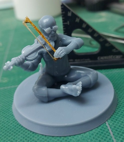
I managed all but the last one piece, the roundhouse port side clamp. Not enough clamps to hold it with glue. Tomorrow is another day. Now for something different... A fellow club member printed some scale 1:64 crew members for my build. Amongst them was a surprise! Two fiddlers seated cross legged. If you look closely the fellow on the right is wearing glasses and looks quite a bit like yours truly. Yup, it is me! So I can put myself in my build. He also printed a larger version at 1:25 ...and at sometime while in my care the end of the bow to the left of the violin strings snapped off. So I carefully removed the rest of it and gingerly removed the frog from between the fingers and thumb with a fine mini chisel while wearing my magnifier. Then I made a new bow from Pau Marfim, stained and varnished. Added hairs from my old drafting brush and slipped it into place. I cut one to simulate a broken hair. It looks a bit too chunky so I'll thin out the stick tomorrow. I had tried to personalise it with hair from ma tête, but it was a bit too unruly... wouldn't be tamed into place.
.jpg.d101af86dbf9dc225e813edcc93dff3e.jpg)
.jpg.39a7ca1bd45389d065468a205c9f2818.jpg)
.jpg.b099b597c7572bdafc3557ae6baf50d5.jpg)

