Bluto 1790
-
Posts
324 -
Joined
-
Last visited
Recent Profile Visitors
1,964 profile views


-
 Obormotov reacted to a post in a topic:
MONTAÑES by Amalio
Obormotov reacted to a post in a topic:
MONTAÑES by Amalio
-
 Obormotov reacted to a post in a topic:
HMS Victory by guraus - scale 1:48 plank on frames
Obormotov reacted to a post in a topic:
HMS Victory by guraus - scale 1:48 plank on frames
-
Javelin reacted to a post in a topic:
HMS Leopard 1790 by Bluto - FINISHED - 1:80 - 50 gun ship - PoB
-
Javelin reacted to a post in a topic:
HMS Leopard 1790 by Bluto - FINISHED - 1:80 - 50 gun ship - PoB
-
Mark P reacted to a post in a topic:
HMS ANSON 1781 by albert - 1/48 - 64 guns
-
Bluto 1790 reacted to a post in a topic:
HMS Trincomalee by Ahoy_there (Lin) - scale 1:72
-
mtbediz reacted to a post in a topic:
HMS Leopard 1790 by Bluto - FINISHED - 1:80 - 50 gun ship - PoB
-
Mark P reacted to a post in a topic:
Marine Clothing room configuration.
-
popash42 reacted to a post in a topic:
HMS Leopard by toms10 - FINISHED - 1:85 scale POF/POB
-
Bluto 1790 reacted to a post in a topic:
HMS Leopard by toms10 - FINISHED - 1:85 scale POF/POB
-
Bluto 1790 reacted to a post in a topic:
HMS Leopard by toms10 - FINISHED - 1:85 scale POF/POB
-
Bluto 1790 reacted to a post in a topic:
HMS Leopard by toms10 - FINISHED - 1:85 scale POF/POB
-
Rik Thistle reacted to a post in a topic:
Help with Proxxon MF70
-
Bluto 1790 reacted to a post in a topic:
HMS Leopard by toms10 - FINISHED - 1:85 scale POF/POB
-
 toms10 reacted to a post in a topic:
HMS Leopard by toms10 - FINISHED - 1:85 scale POF/POB
toms10 reacted to a post in a topic:
HMS Leopard by toms10 - FINISHED - 1:85 scale POF/POB
-
 WELL DONE, TOM! . . . CONGRATULATIONS! She's looking superb, with the sails filled with all the available wind! When I look at mine now it almost looks unfinished - - - the sails make a big difference. And 4 1/2 years? . . . mine took me 9 years although there were a few lengthy lay-off periods.
 -
Bluto 1790 reacted to a post in a topic:
HMS Leopard by toms10 - FINISHED - 1:85 scale POF/POB
-
Bluto 1790 reacted to a post in a topic:
HMS Leopard by toms10 - FINISHED - 1:85 scale POF/POB
-
Bluto 1790 reacted to a post in a topic:
HMS Leopard by toms10 - FINISHED - 1:85 scale POF/POB
-
Bluto 1790 reacted to a post in a topic:
HMS Leopard by toms10 - FINISHED - 1:85 scale POF/POB
-
Bluto 1790 reacted to a post in a topic:
HMS Leopard by toms10 - FINISHED - 1:85 scale POF/POB
-
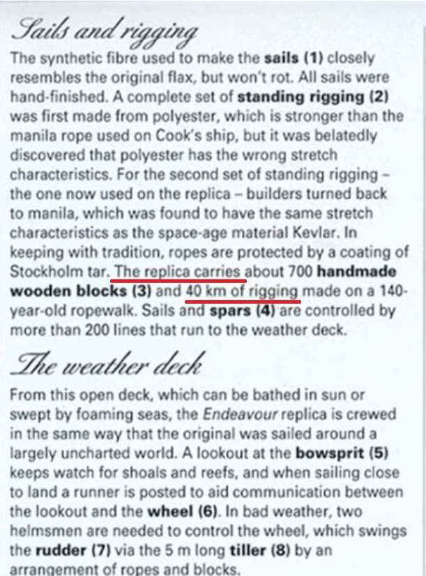
Hi Tom, Your progress is looking amazing on your Leopard! I hate to dis-illusion you ~ but I think you've been undersold on the info you read about the length of all the rigging ropes on one of these sailing ships! I have read (and yes - for the moment I can't find the source!) that the length of rigging on the 1988 replica of HMB Endeavour was around 14 miles. I've just been searching Google for the info and saw 30Km (approx 18.75 miles) quoted in one place, and on another site - this one > HM Bark Endeavour. Australian National Maritime Museum, Sydney - Travel To Eat it stated the length of rigging as 40 Km (approx 25 miles). Here's a screenshot from part of that webpage > Since Endeavour was considerably smaller than one of these 50 gun ships it would seem logical that the latter would carry even more (longer total length) rigging ropes.
-
You say "slow but steady" ~ well, the way the wind is filling those sails already that ship will be zipping across them waves! Looking great!
-
Hi Tom, That sail is looking great! . . . and what a lot of work just in one sail. How did you get the 'wind in that sail'?
-
Such luxurious cabins !!! I want to sail on this ship when she is finished! When I see work of this standard I feel I should cancel my membership of the forum. A-M-A-Z-I-N-G !
- 589 replies
-
- 3
-
-
- le gros ventre
- cargo
- (and 2 more)
-
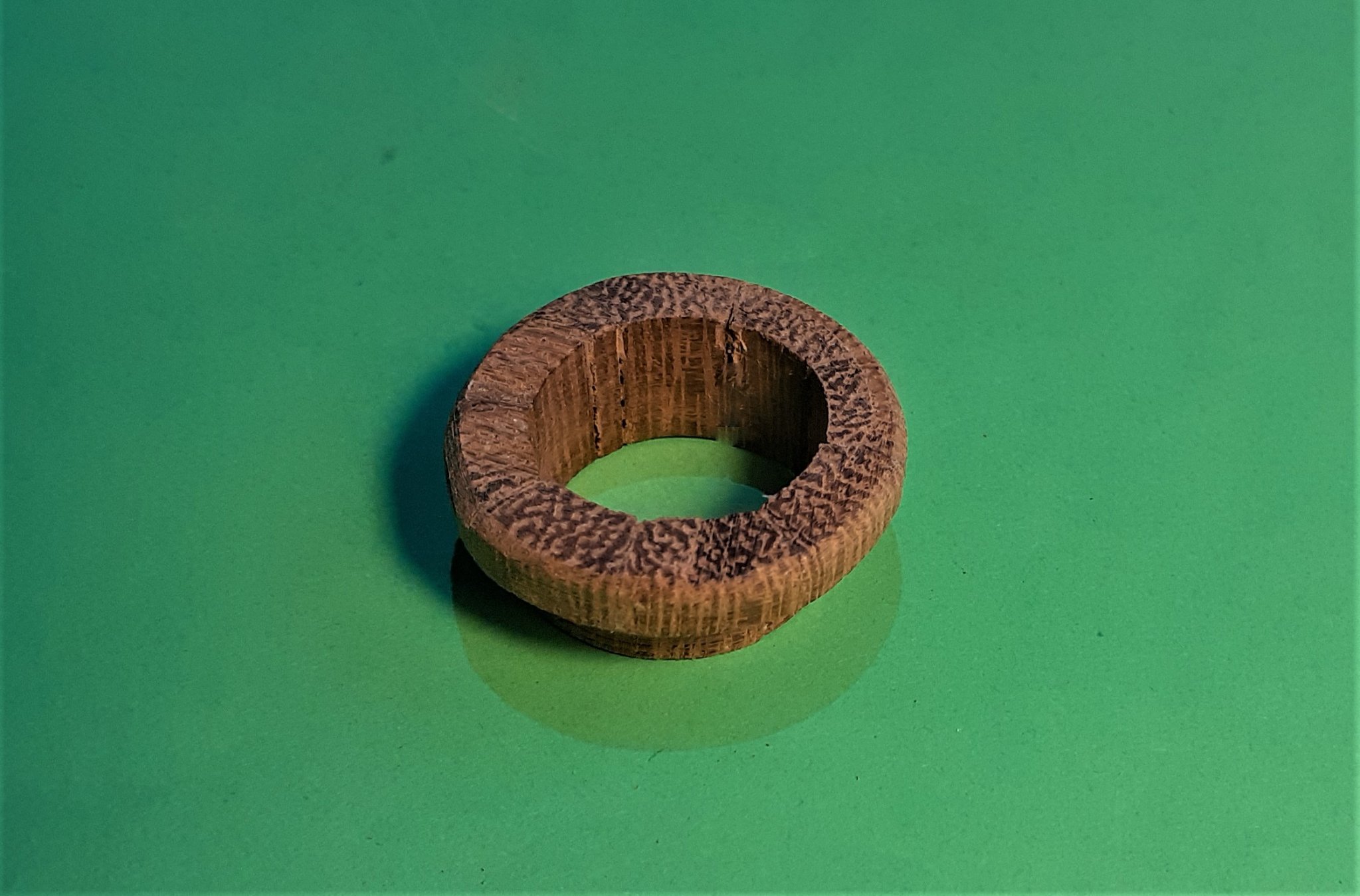
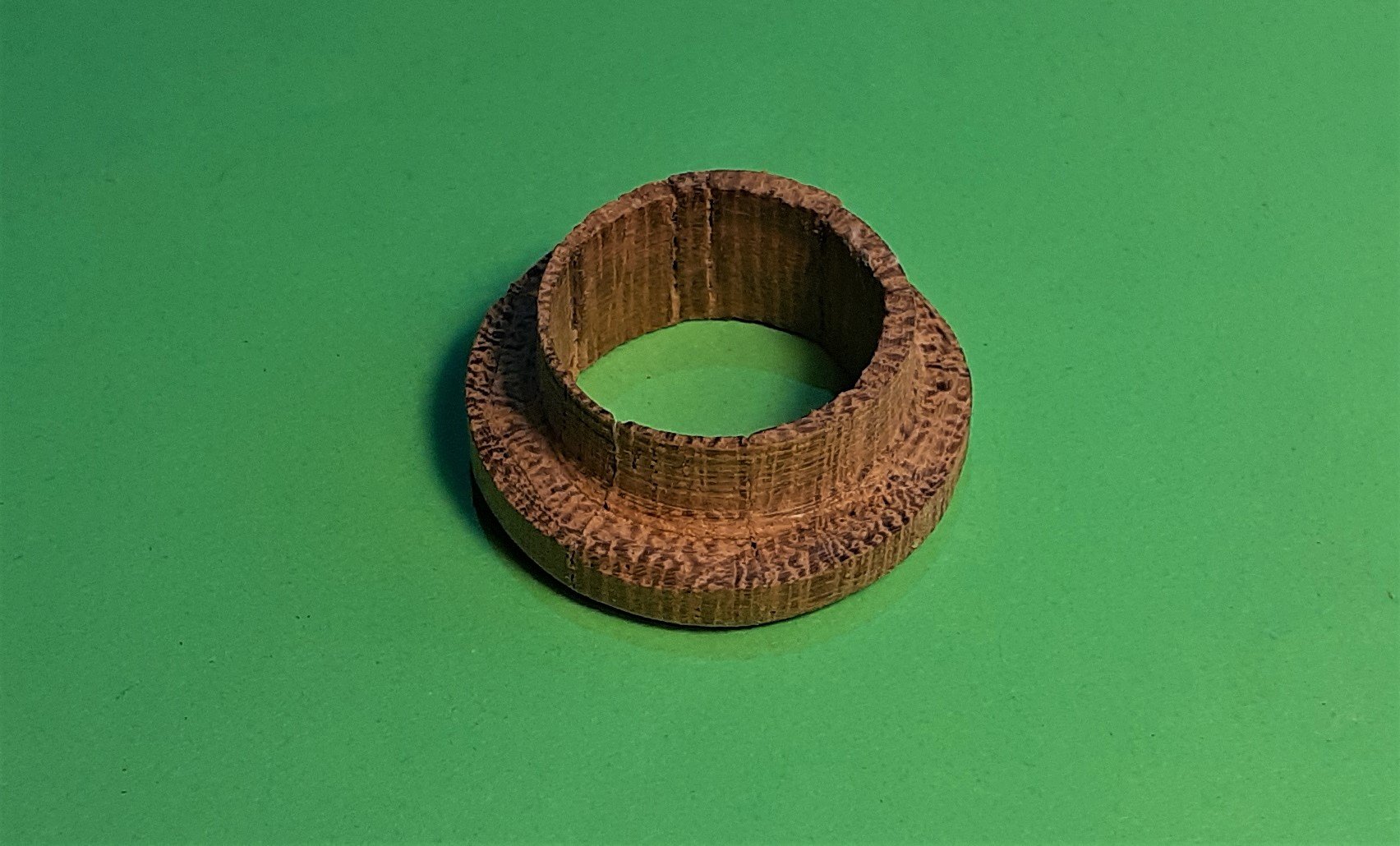
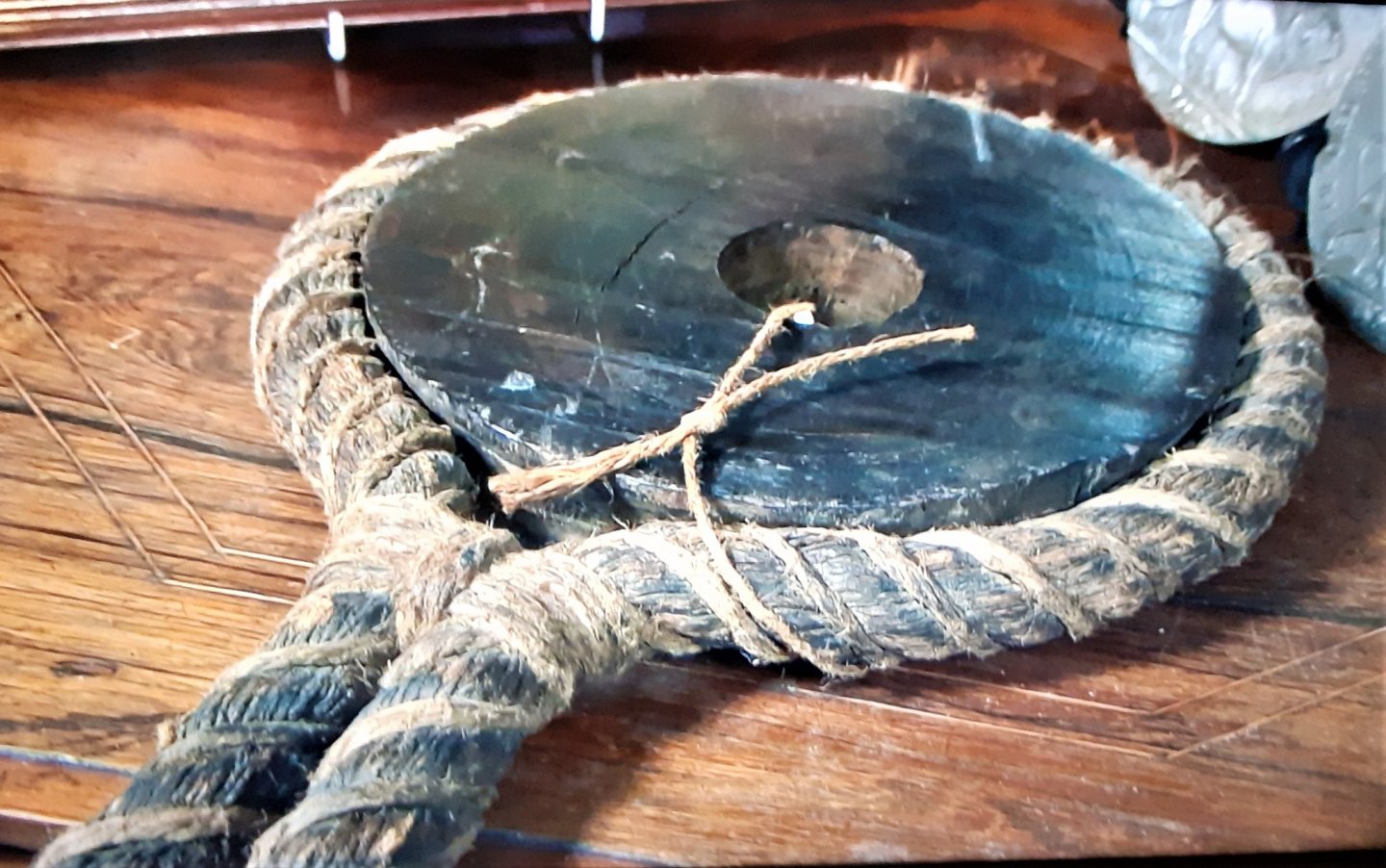
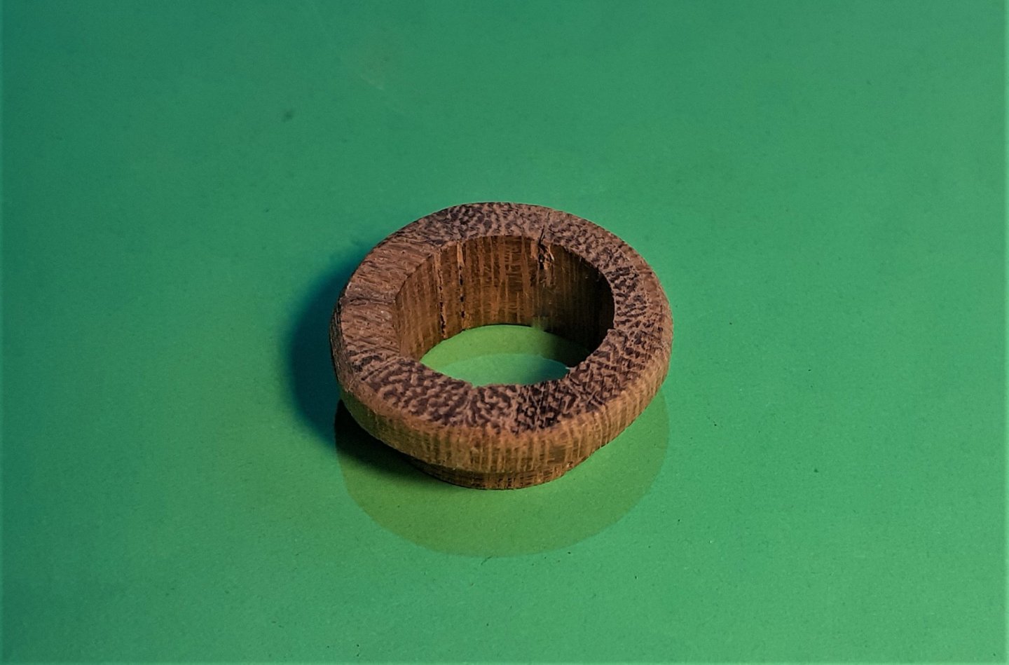
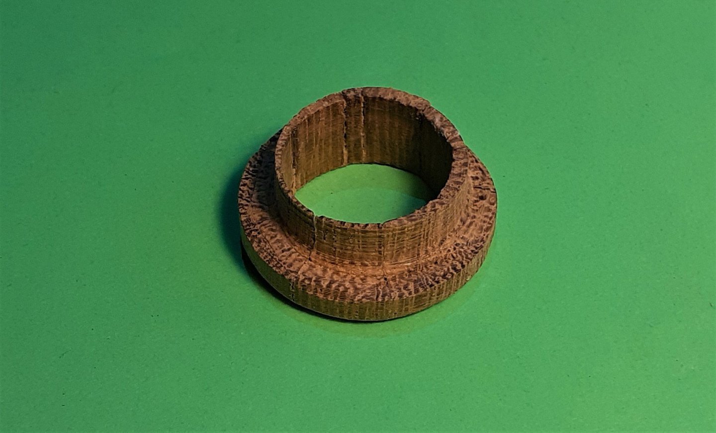
Thanks Bruce, Gregory and Druxey for your comments. In view of your comments and having looked at the 'item' again, I feel I have to believe the wooden part was in fact the sheave out of a block and that someone has indeed 'decorated' it with some 'old rope'. In its present appearance I can't imagine it would have any practical use ~~~ and that's why I asked the question . . . as I couldn't imagine how it would be used!
-
Bruce, it was on today's edition of "Bargain Hunt". He didn't actually say it had been under water for over 200 years but he did say something like 'it was his prized possession from the wreck of HMS Invincible', so I assumed that it had been salvaged after having been 'down there' for some time. The site of the wreck was discovered in 1979.
-
Watching an antiques program on TV this item was described as having been salvaged from the wreck of HMS Invincible. (Captured from the French Navy 1747 and sunk 1758) The item was described as a "pulley". I would expect a pulley to have been fitted with a rolling sheave but this item appears as a flat circular piece of wood with just a round hole at its centre ~~~ so, for what would it have been used, and HOW would it have been used?
-
HI Tom, "Splicing the main brace" is an expression in very common usage but I reckon that more than 99% of people using it don't know its origin and original meaning -- just like so many other old expressions, so don't feel silly! . . . and milestones! . . . that's the thing about this ship building -- there are so many milestones and it's great when we get to each one and tick it off! Once you get the yards on and rigged it's going to look complete but if you're adding sails it's going to be even 'more completer'!
-
Thanks for the comments and likes. Michael, there are quite a few items in my build that have been copied from other builders, but if there is anything that you (or anyone else) wants to copy from my 'stuff' then I'm well flattered! Tom, about the only 'fancy machine' I have is my mill. The mill and the bandsaw are the 2 most used machines in the build, with an occasional use of the drill press for larger diameter holes. The mill is also used as a drill press for small holes from around 3mm down to 0.5mm. Oh, almost forgot the drill powered lathe/jig I use to make 'round things'.
-
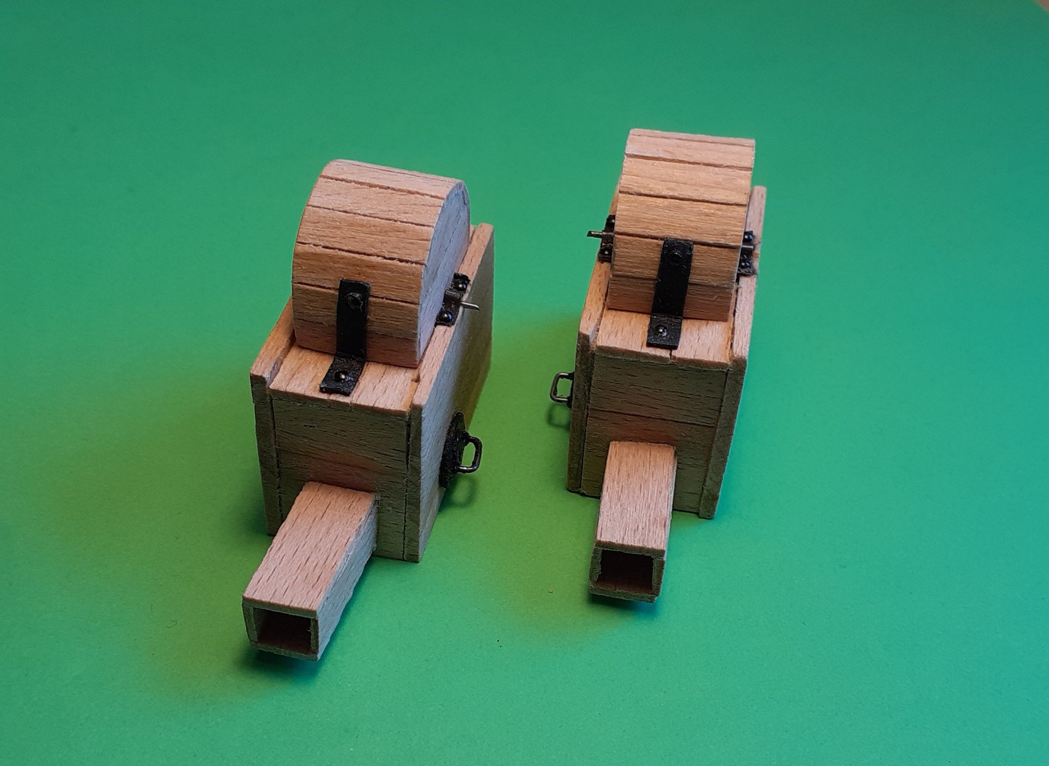
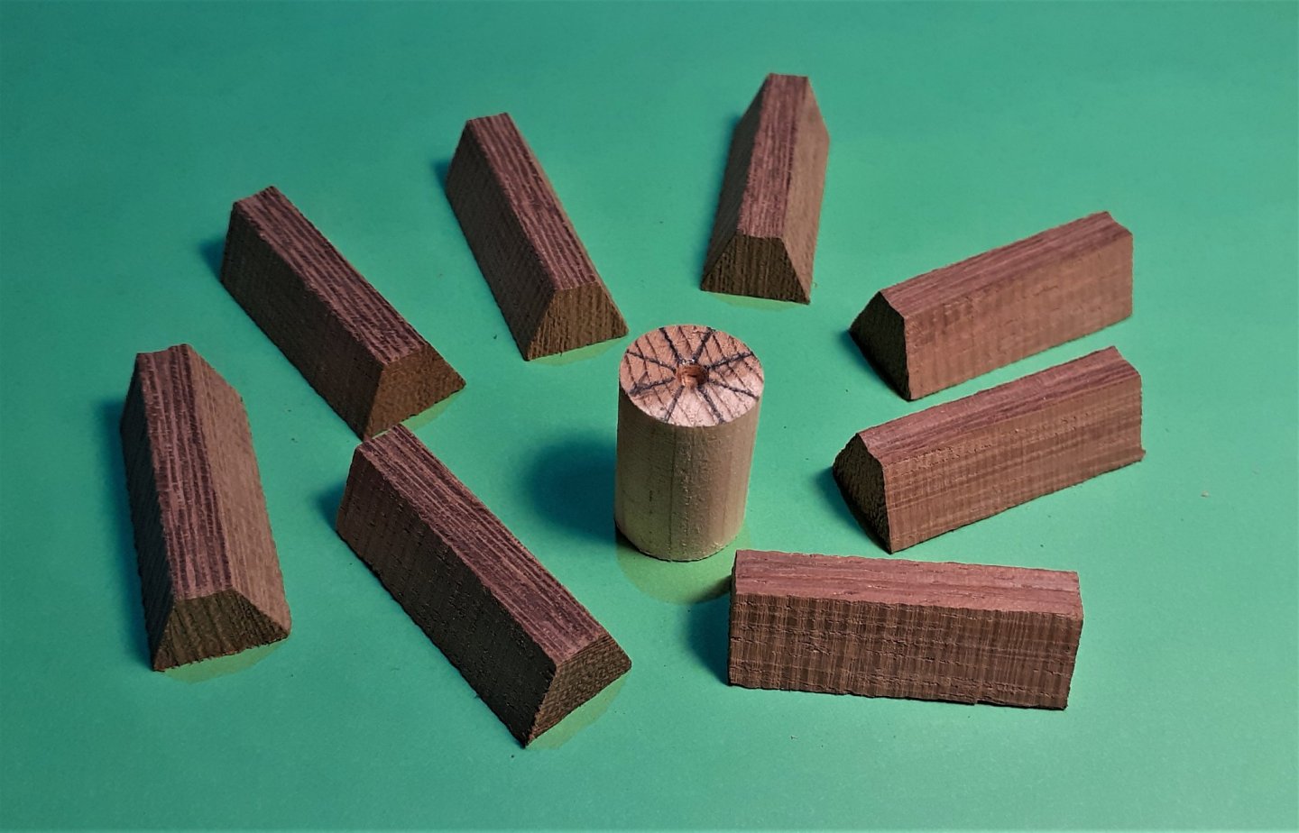
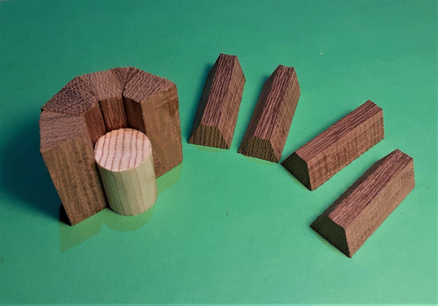
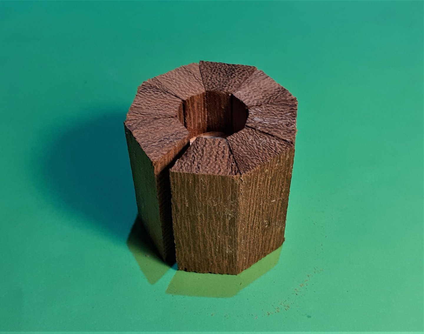
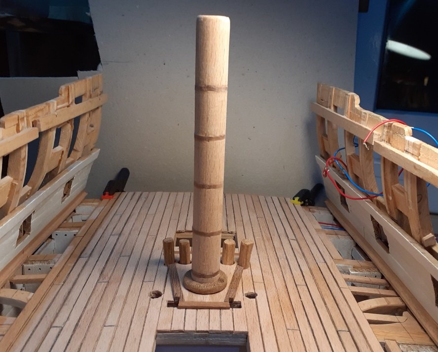
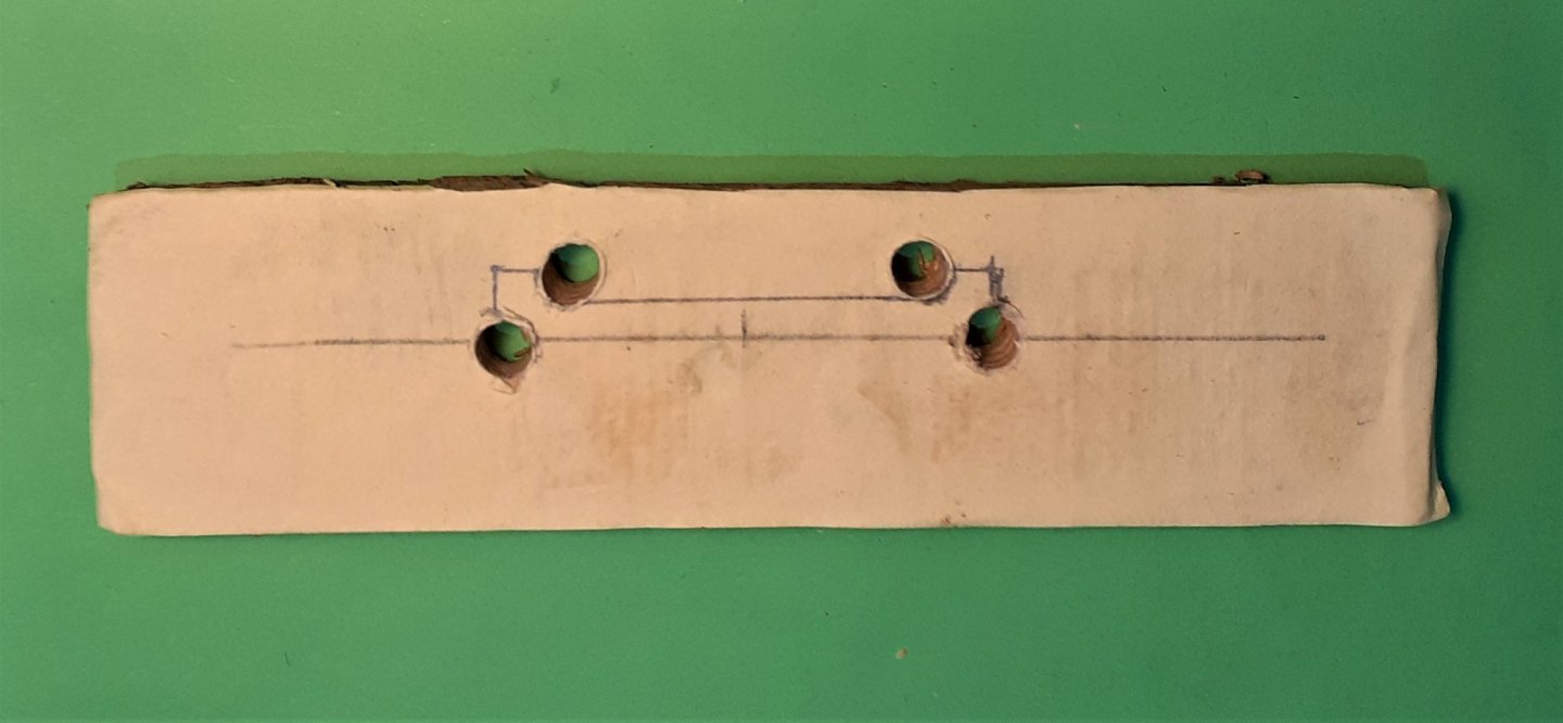
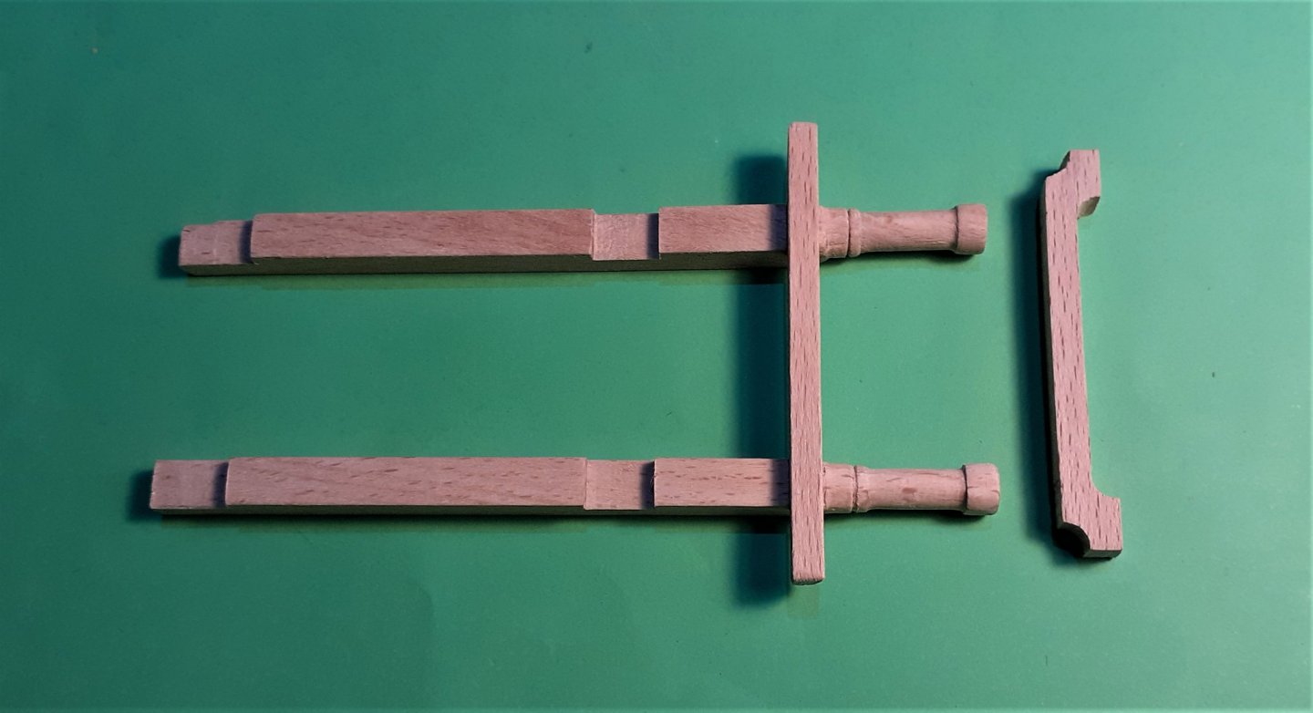
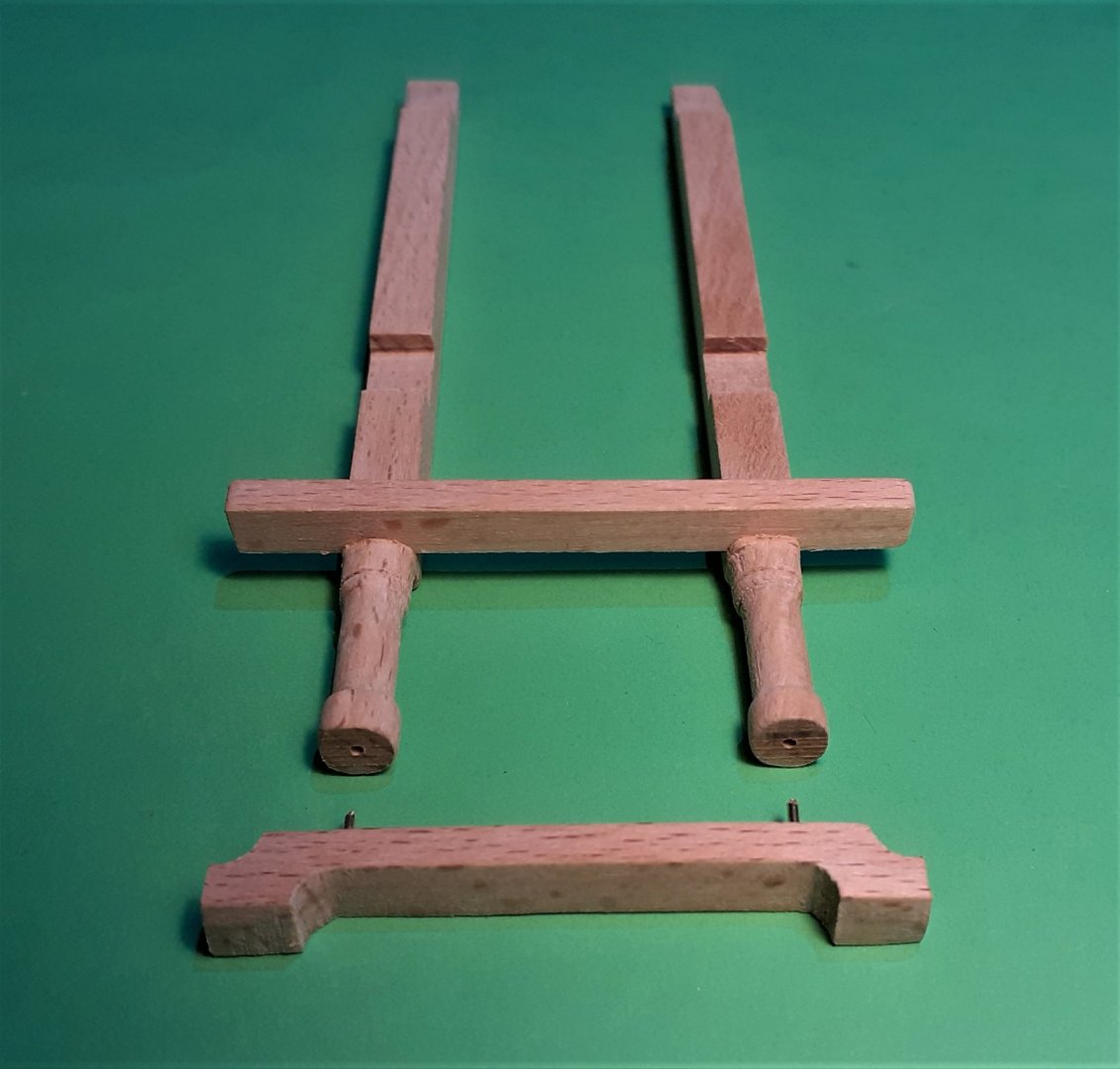
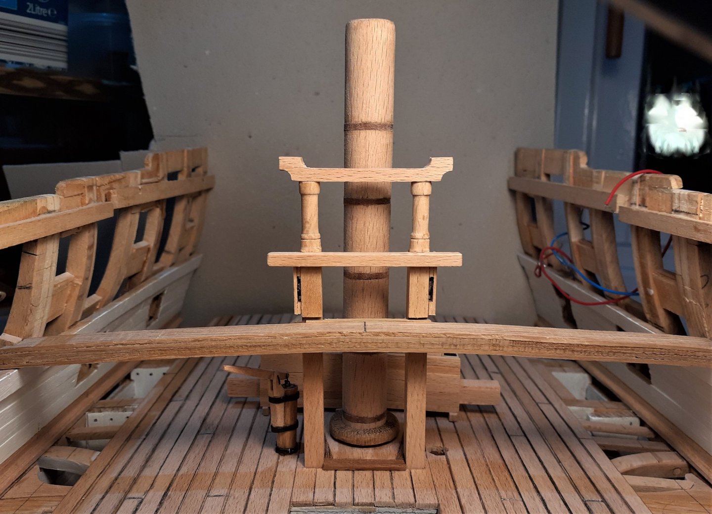
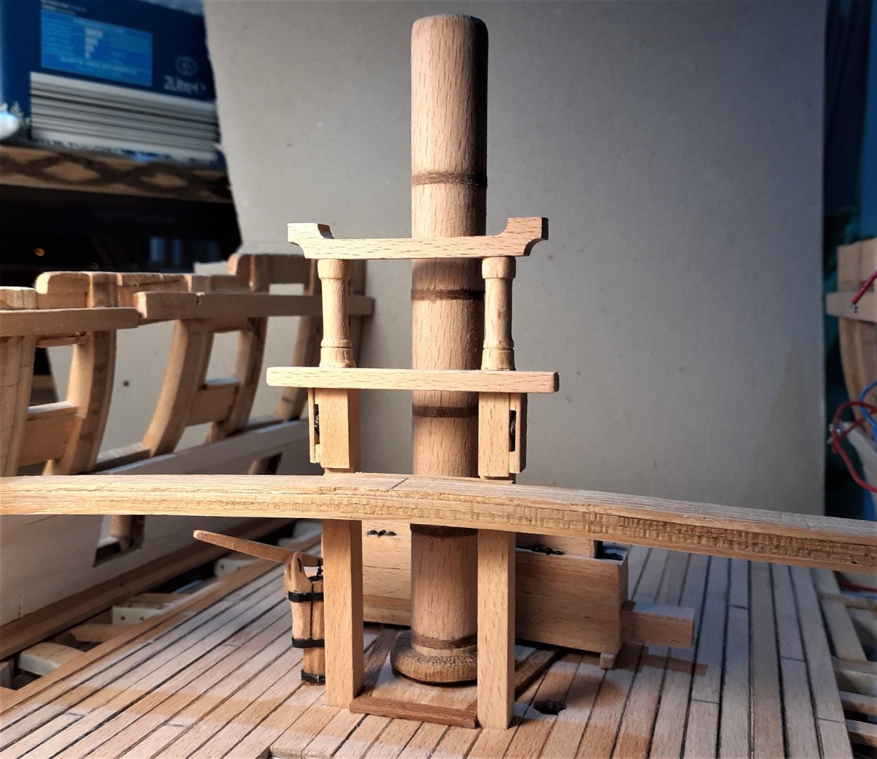
Thanks for the thumbs ups and the visits. Making the mast was reasonably straightforward -- making the mast wedges had me thinking for a while. As I don't have a 'proper lathe' just a drill in an attachment and only having a standard drill chuck I couldn't create the wedges in the way I've seen them done here on the forum. So I turned a short length of softwood down to the same diameter as the mast at lower deck level. I tried to calculate the size of wedges that would be required for 8 wedges. These wedges were glued on around the 'dummy mast' leaving an unglued section > With all 8 glued on there was a small gap of about 1.5mm > With the gap filled the inside diameter was just a hair too tight for the mast so that small sanding drum did enough to make it a snug fit > With some work on the bandsaw and with a little bit of invention, I was able to finish it off on the lathe; Right way up > Upside down > and in position > With the mast > The sheet bitts still needed the top cross piece. I drew it to scale on paper and glued that onto a piece of beech. For the 4 quadrant curves I drilled 4 holes with a 6mm drill bit at the drill press. That was the first attempt -- a couple of the holes weren't exactly where they should have been but the second one came out OK. A couple of pieces of brass wire helped hold it in position while the glue dried > and with the 2 sheaves attached > and just to see how it all looks >
- 66 replies
-
- 13
-
-
Hi Tom, Is that very fine mirror a prototype for one you're going to model for Leopard!!! Looking at your layout plans for your pins looks scary! I just did the standing rigging on mine and even that required a LOT of belaying points ~ rigging the sails will sure need a lot more. I'm really looking forward to seeing it with all sails flying!
-
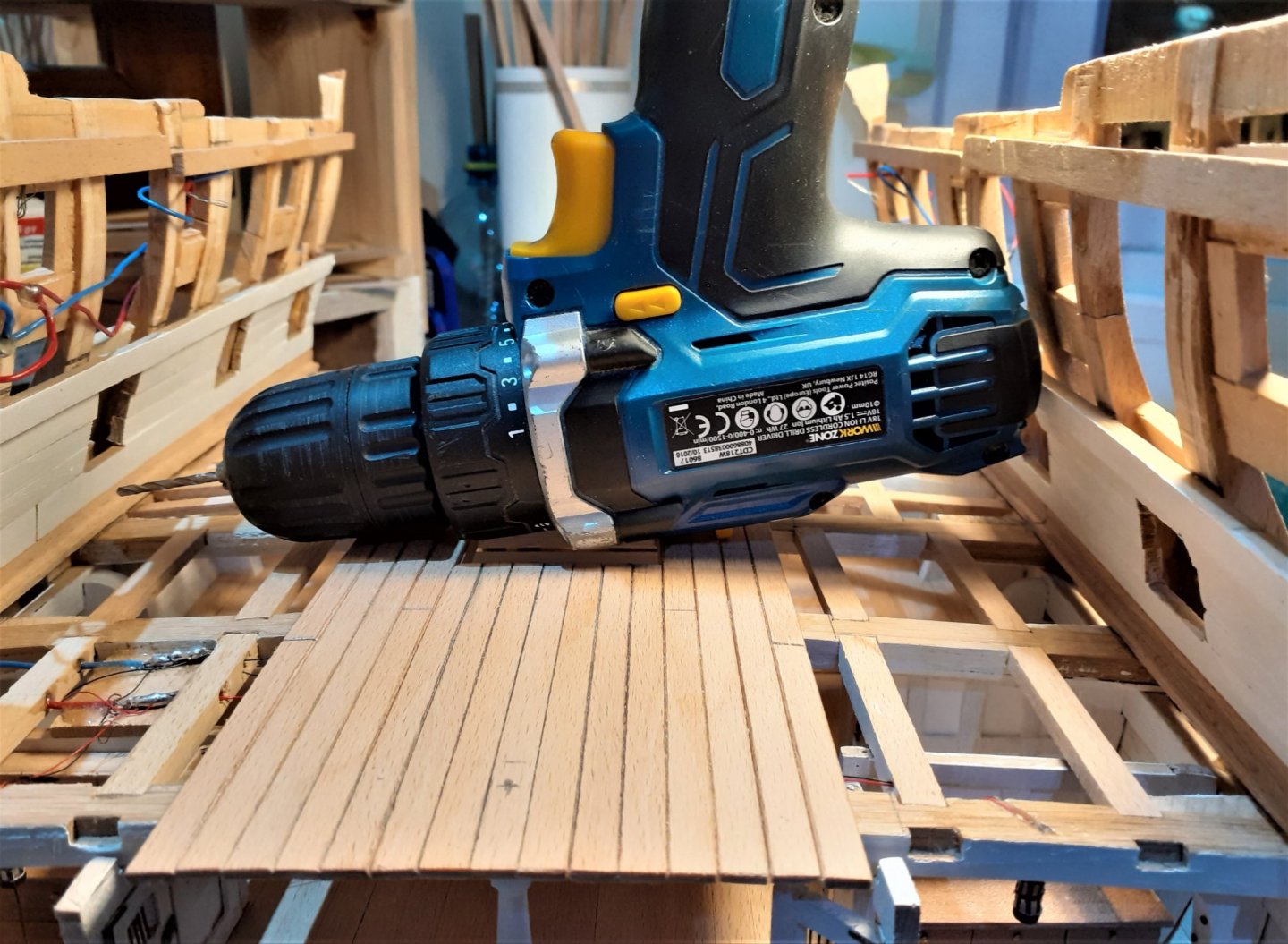
Hi Tom, I have to confess that I cheated a little when I made the yards on my other build! I didn't try for 'octagonalism' the way you did ~ on the mid section of the yards I glued on 4 thin pieces of timber at regular places around the yard. After a light sanding with a sanding stick that mid section was having the appearance of being octagonal - - - and up there on the masts, with all the rigging going on around them it's not very obvious that they're not perfect! Now, seein' as I'm on here I'll post a few other pics. Did the mast foot tenon and here is the mast, together with the other 'stuff' having a dry test fit > Some of the above photos reveal that the mid section of that deck has been planked. I can confess that I cheated a little with that planking ~ I used full lengths for each full plank fitted so far. At the points where 2 planks would butt against each other I used a craft knife to cut a groove deep enough to mark with a black pencil lead to simulate the joints. For the 'caulking' between the plank edges I also used the black pencil but I didn't just mark the planks along their edges. I ran the knife along the top edges at around a 45° angle, creating an almost imperceptible chamfer, then ran the pencil along these chamfers. The black edges and joints are almost visible in this photo! > Before fitting any of these items around the main mast area I wanted to get the inner hull planking done as I imagined it could be very tricky trying to drill into the hull sides for the gun tackle eyebolts if the deck isn't clear of mast and pumps etc. There's still enough space at that level to be able to get a cordless drill in there >


- 66 replies
-
- 10
-
-
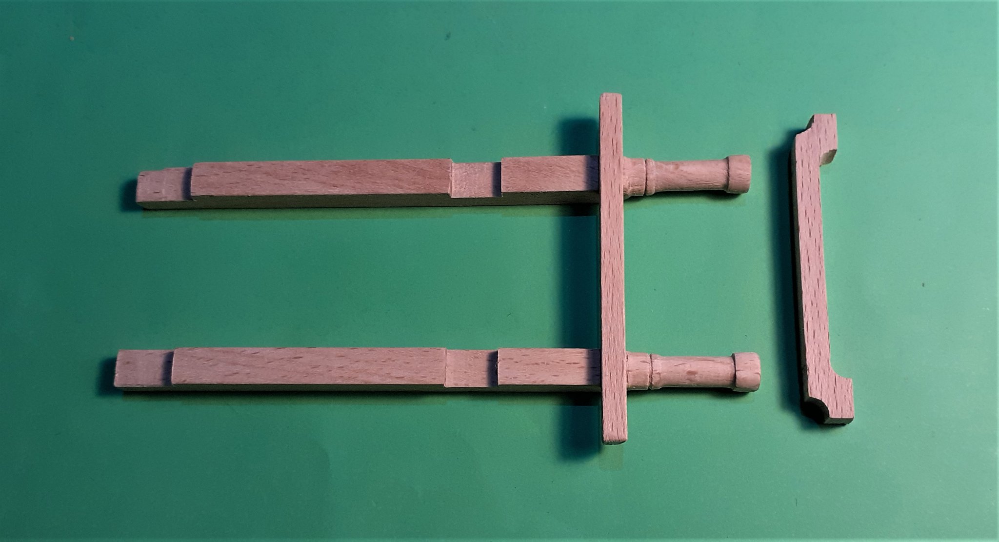
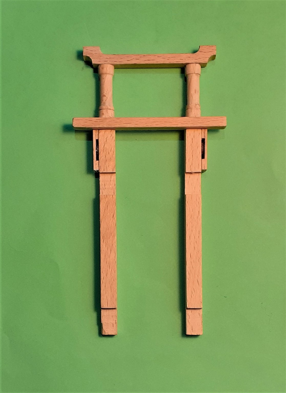
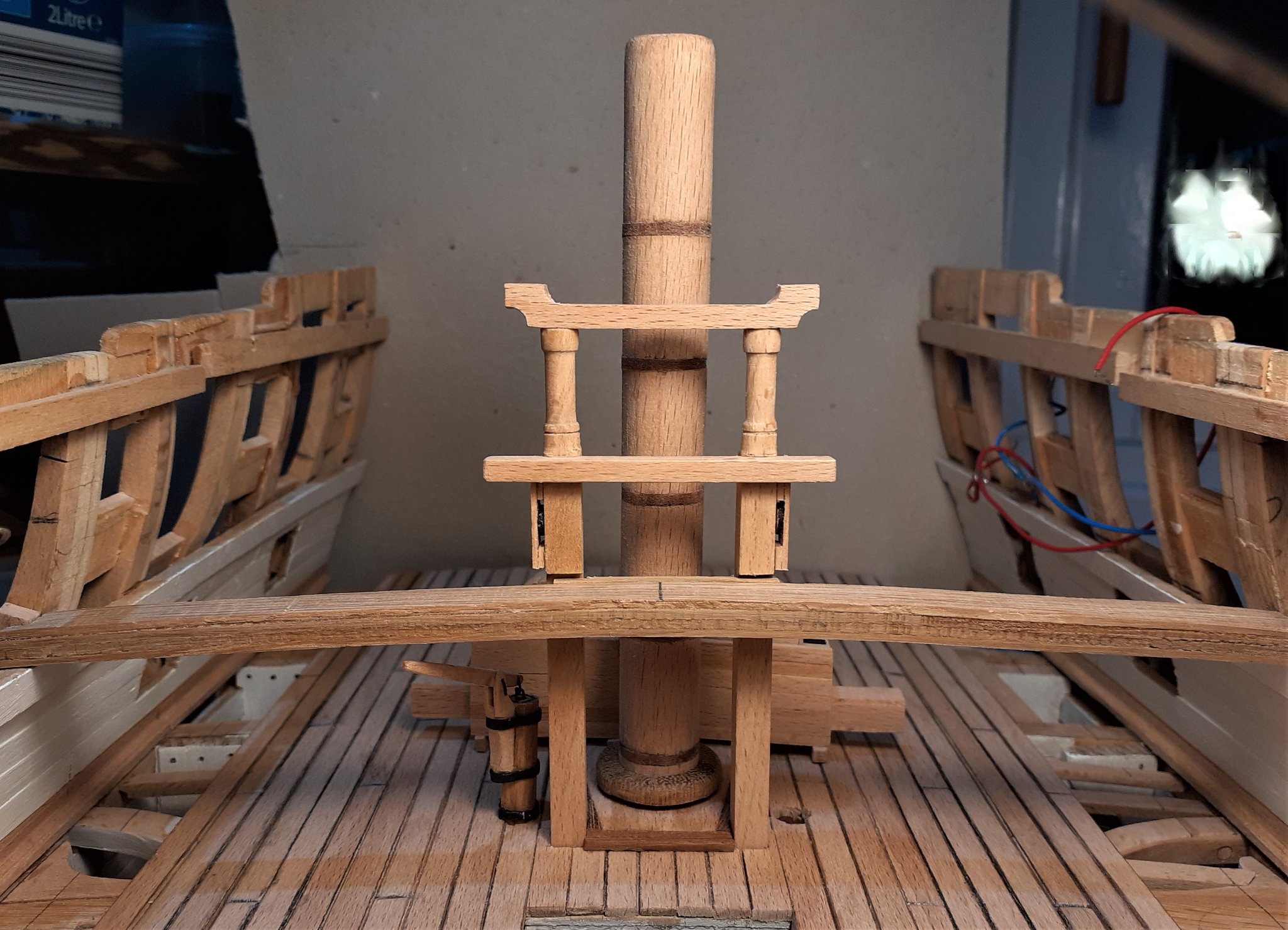
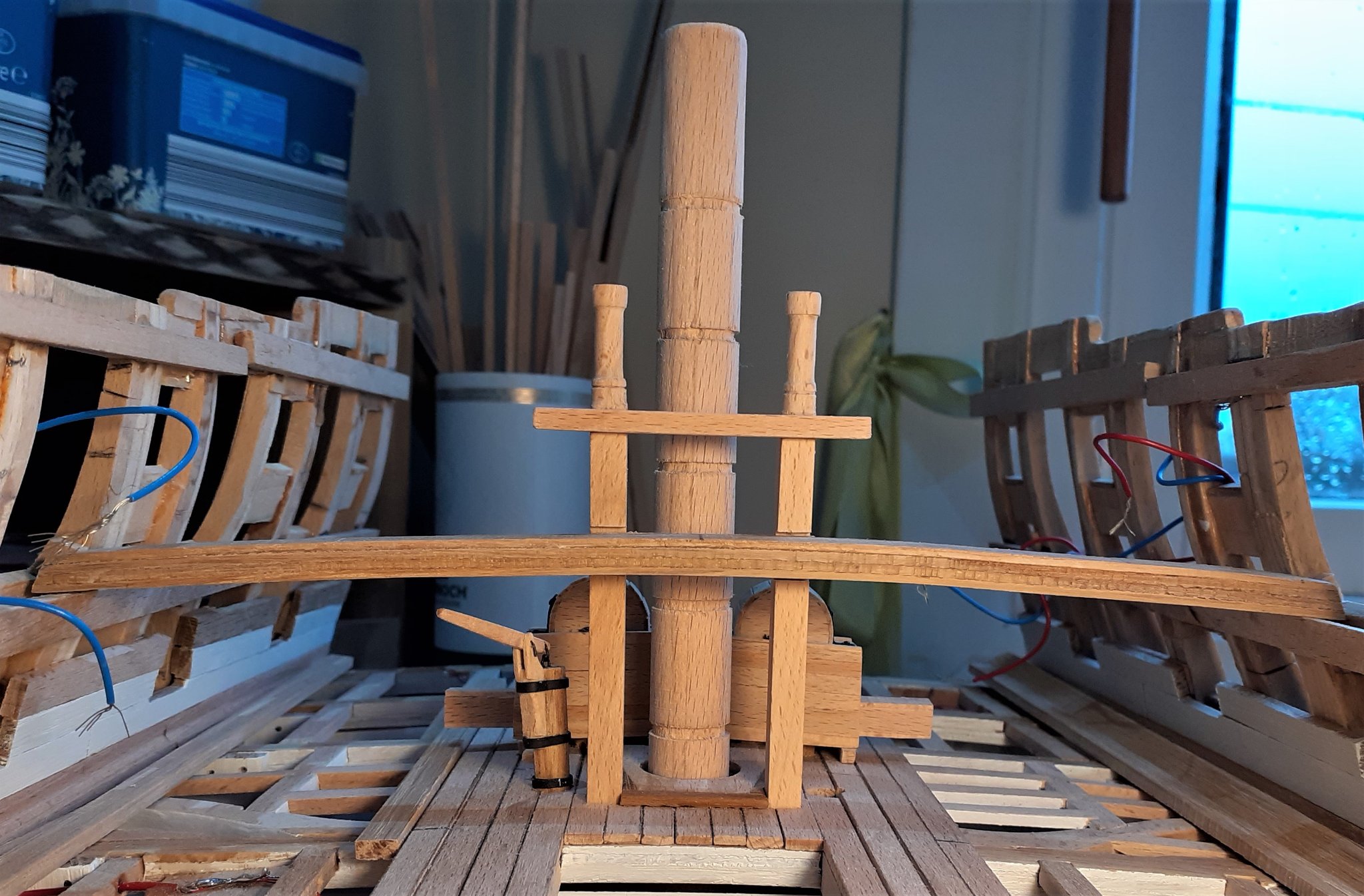
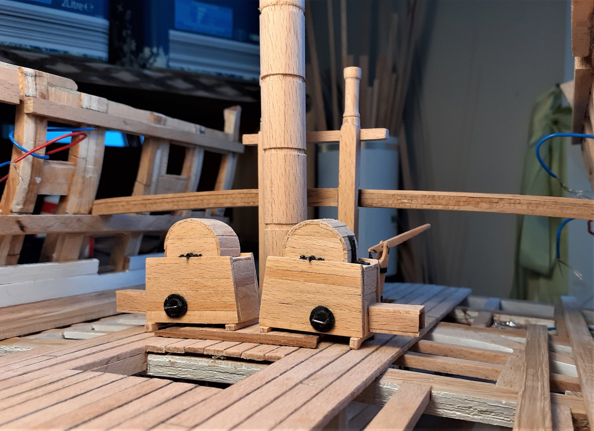
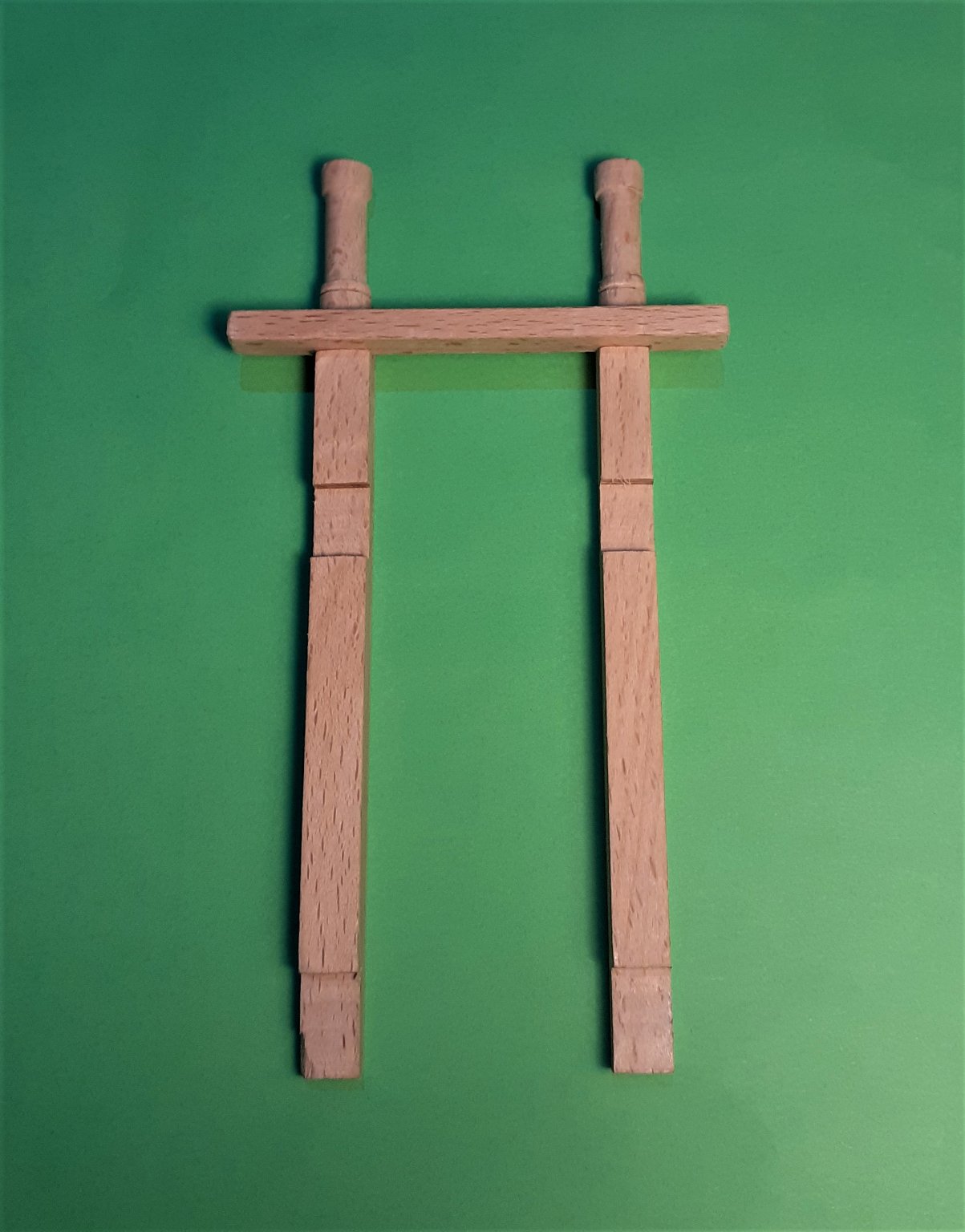
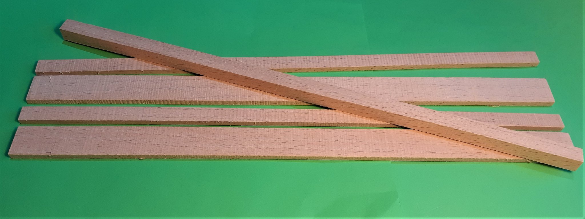
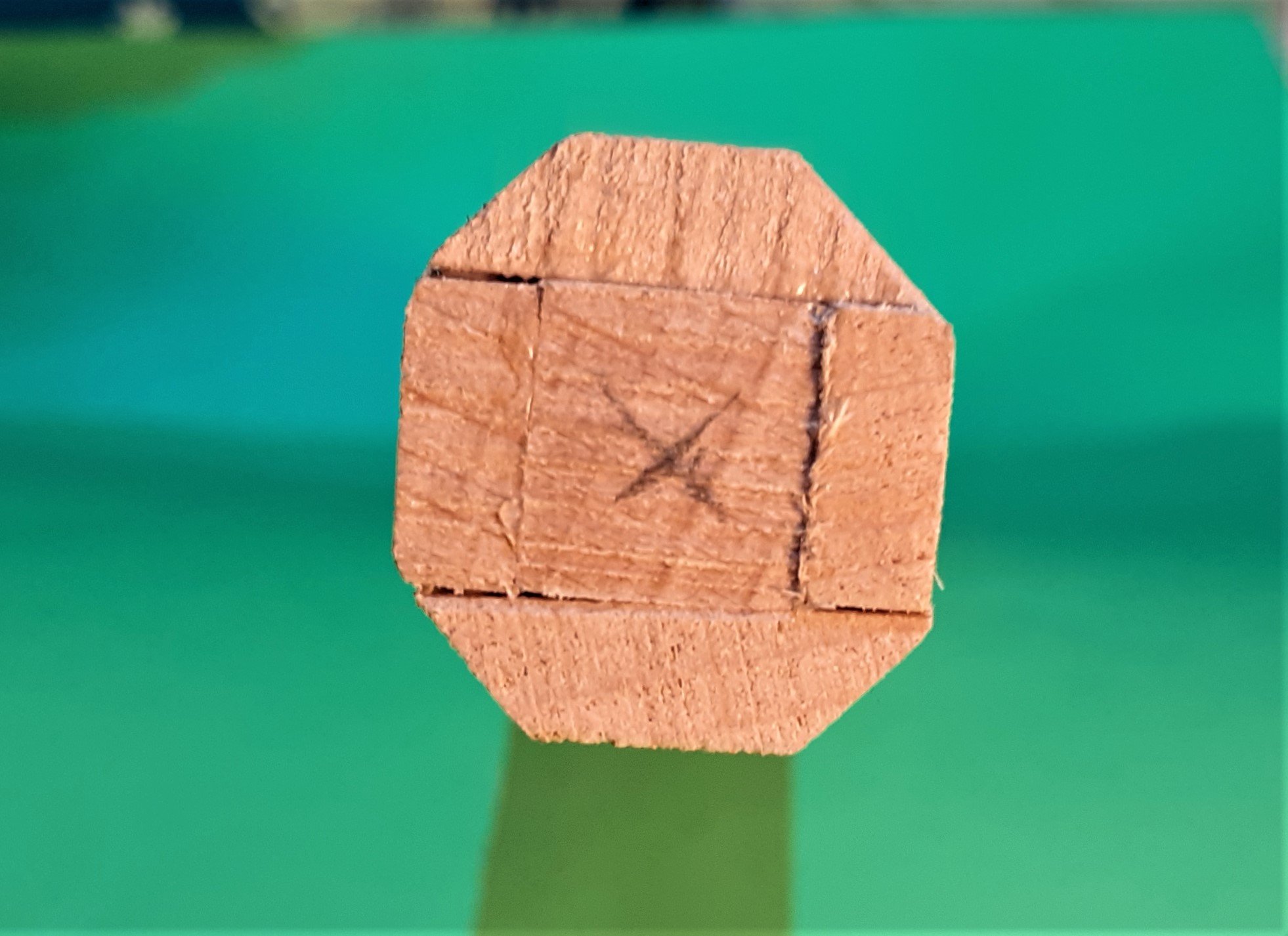
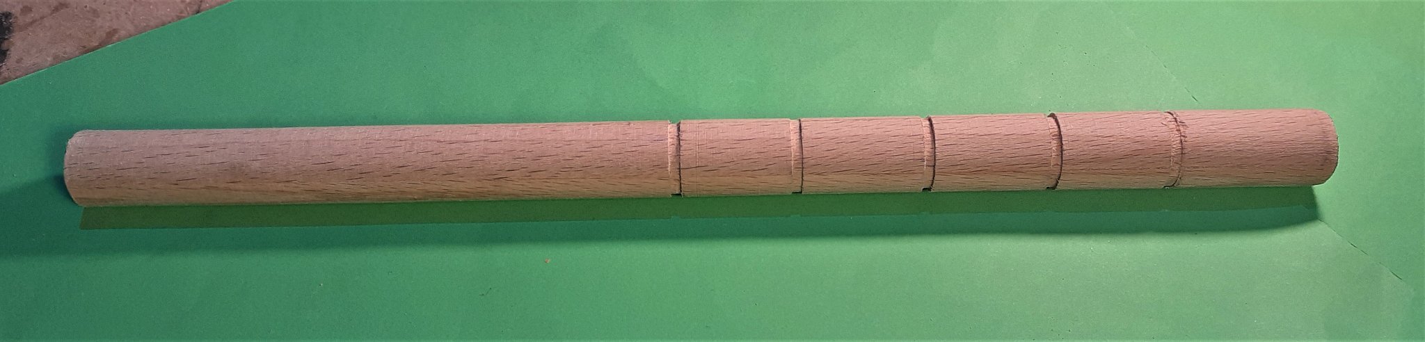
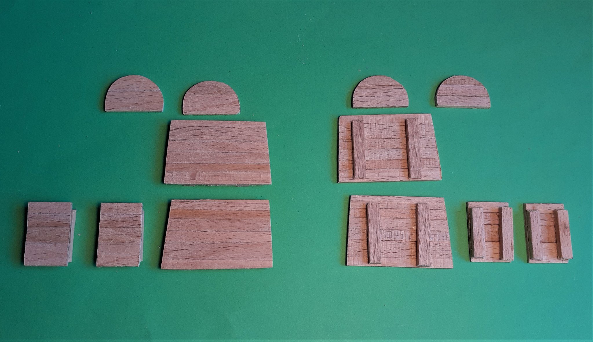
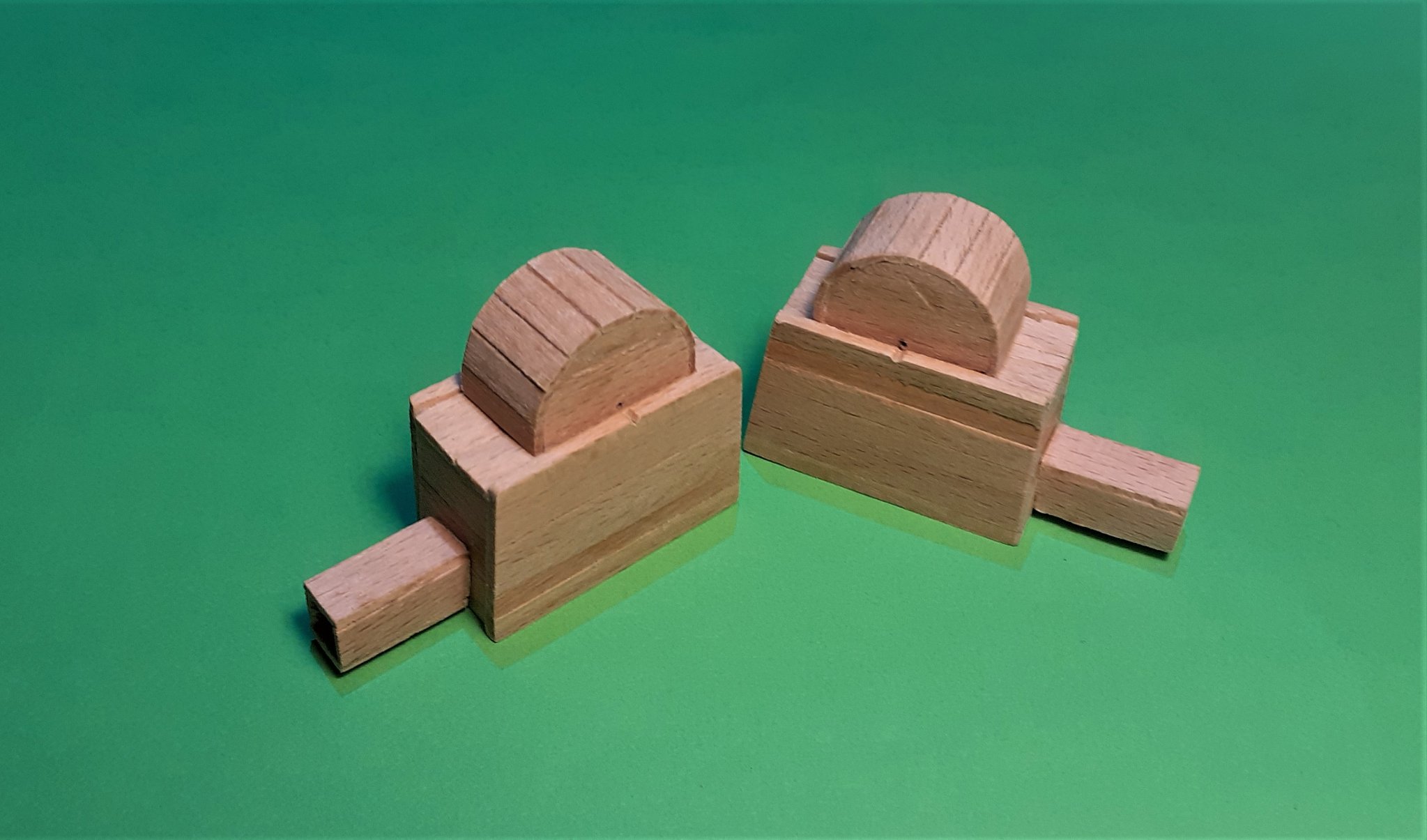
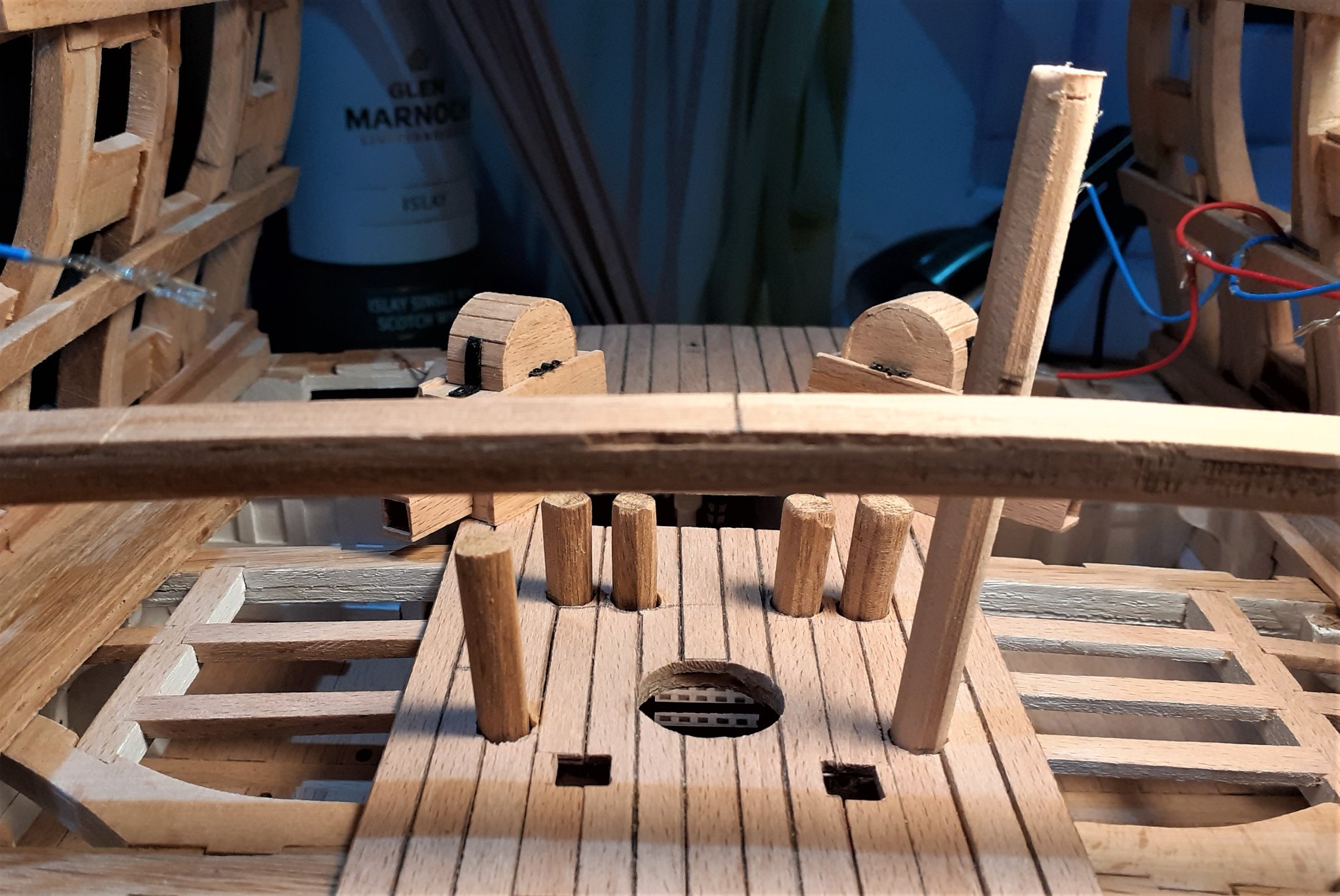
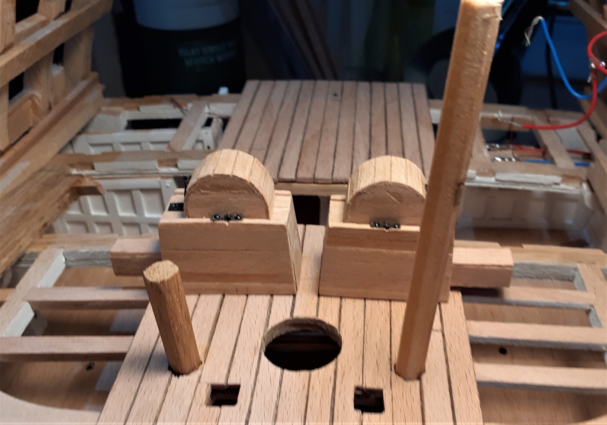
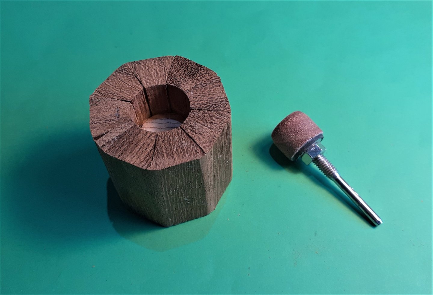
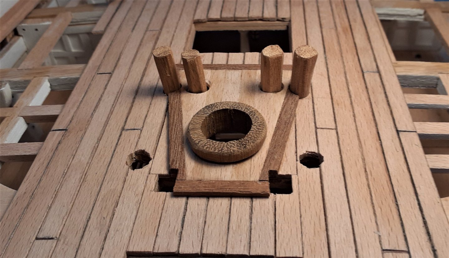
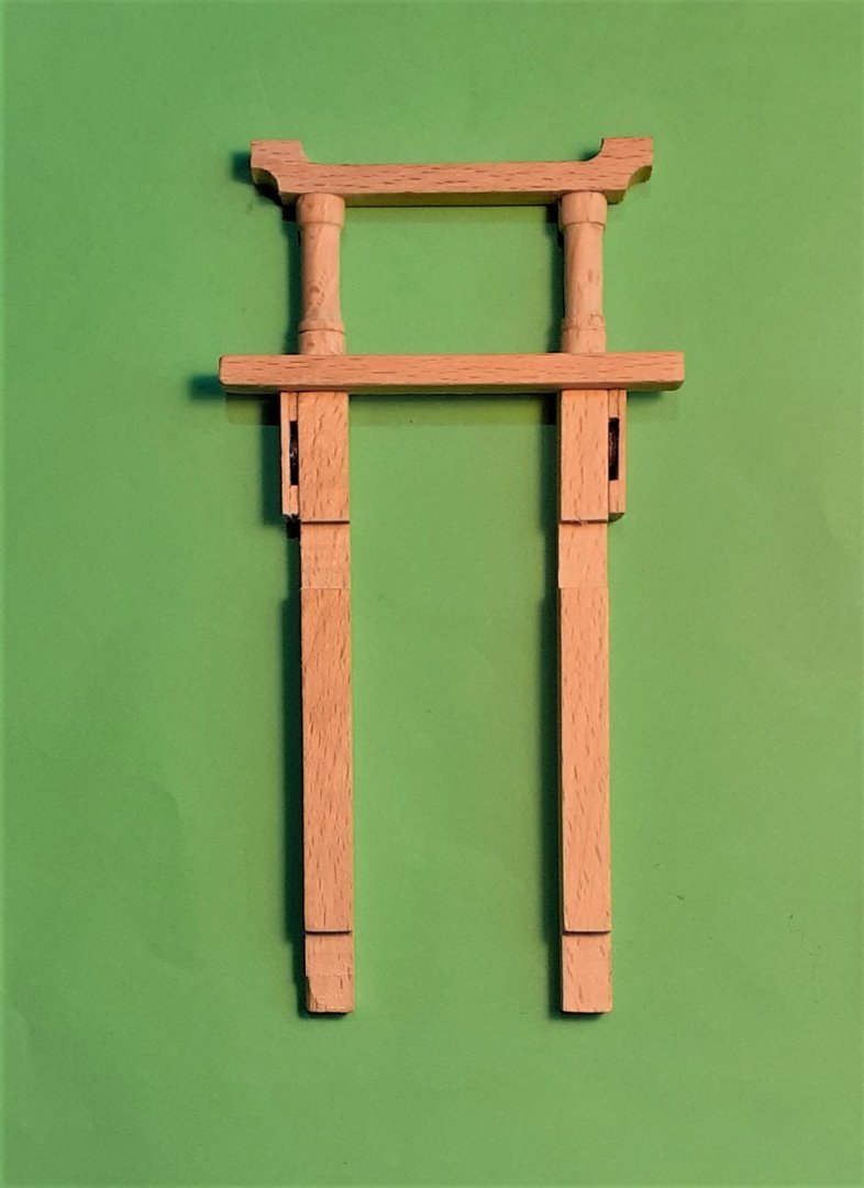
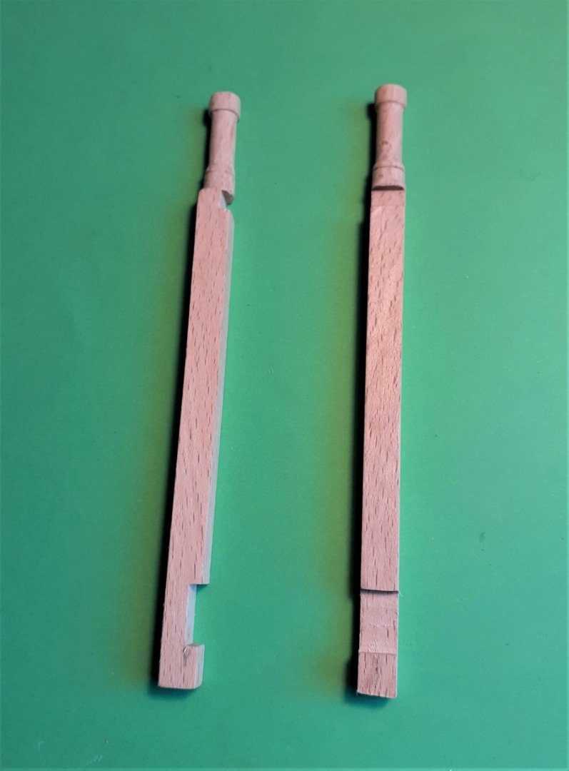
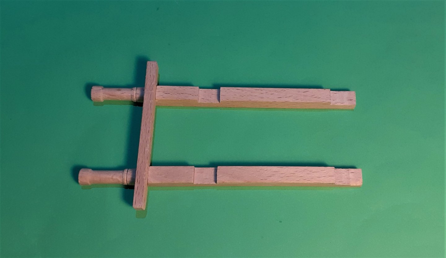
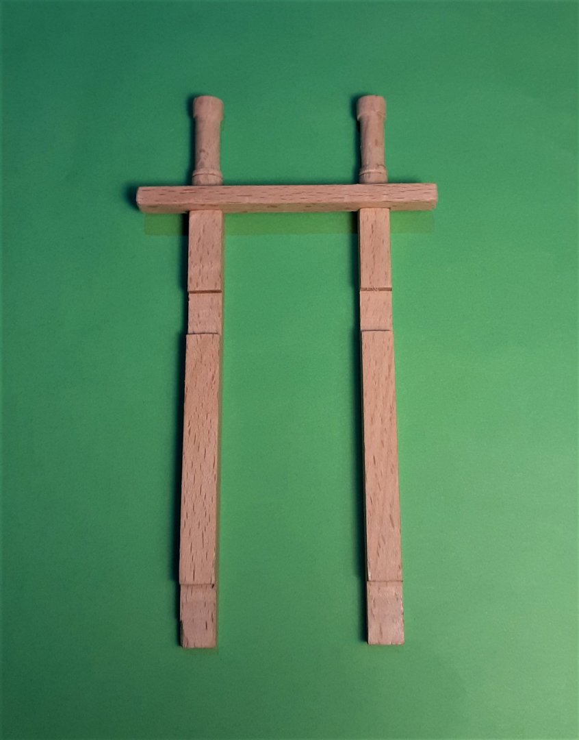
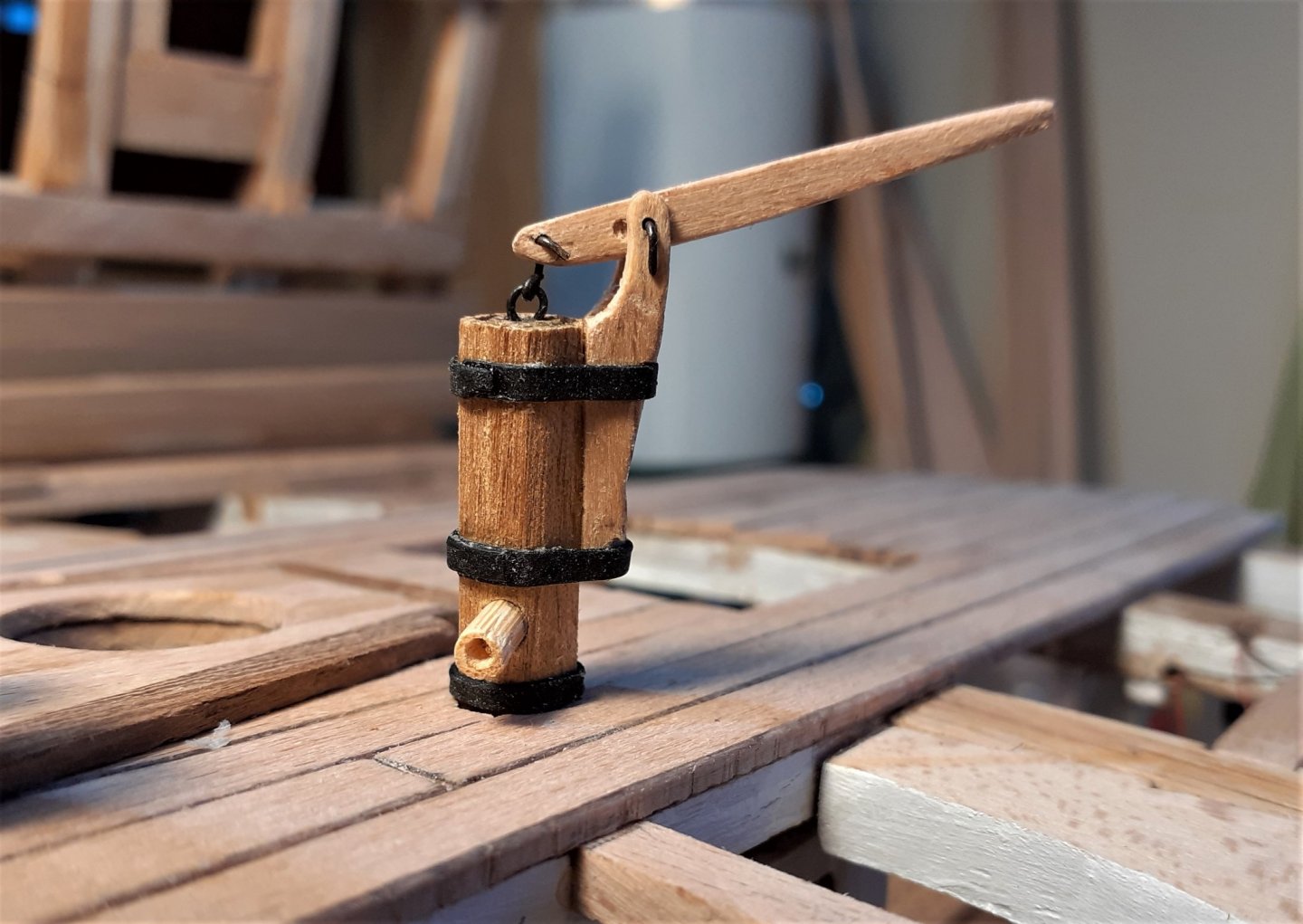
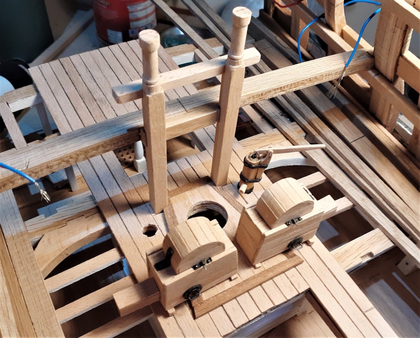
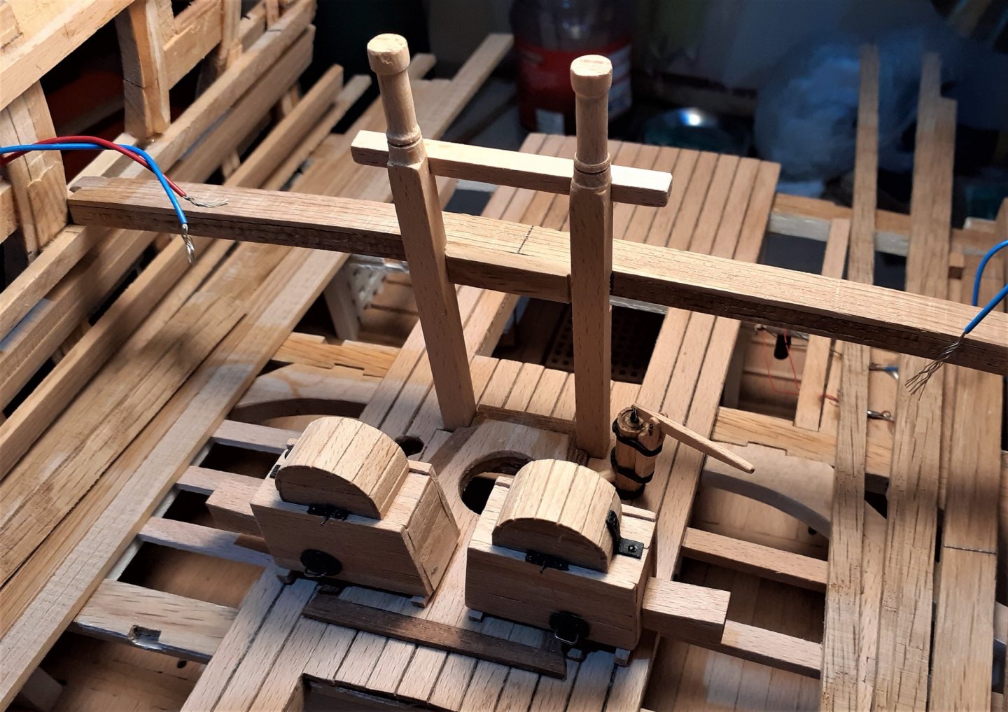
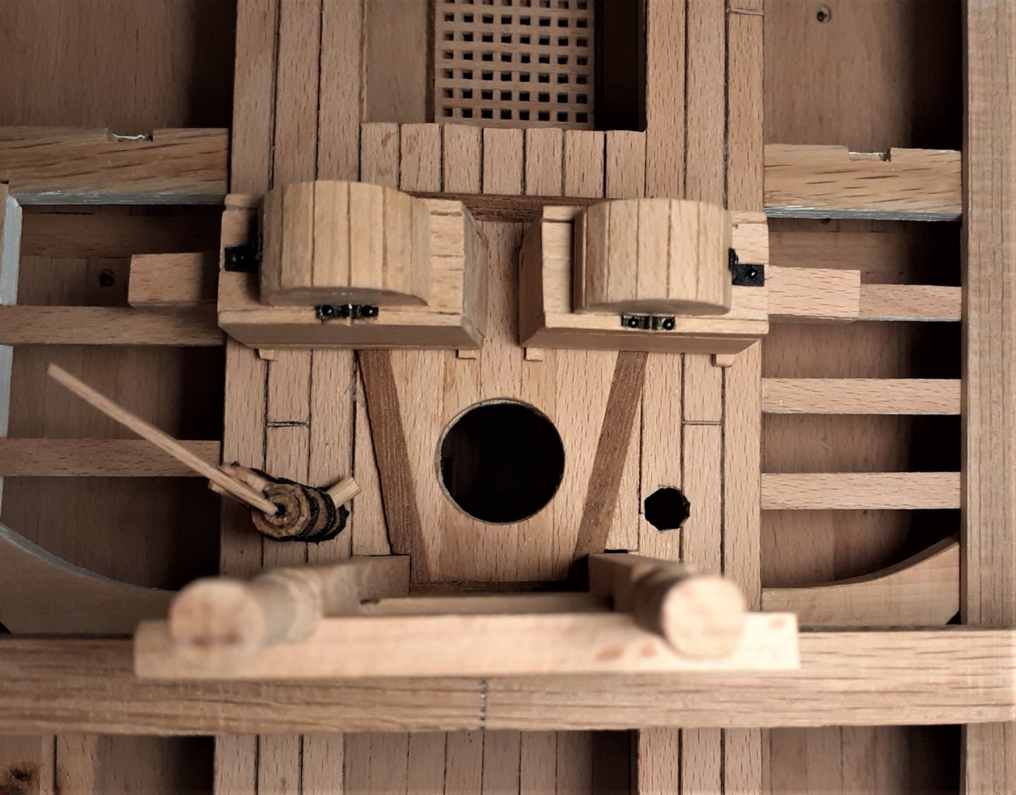
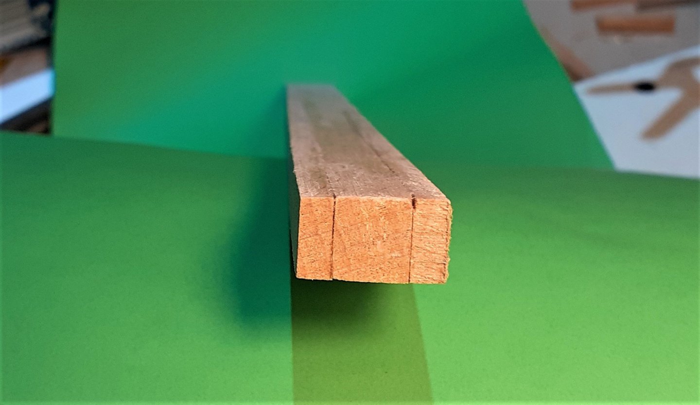
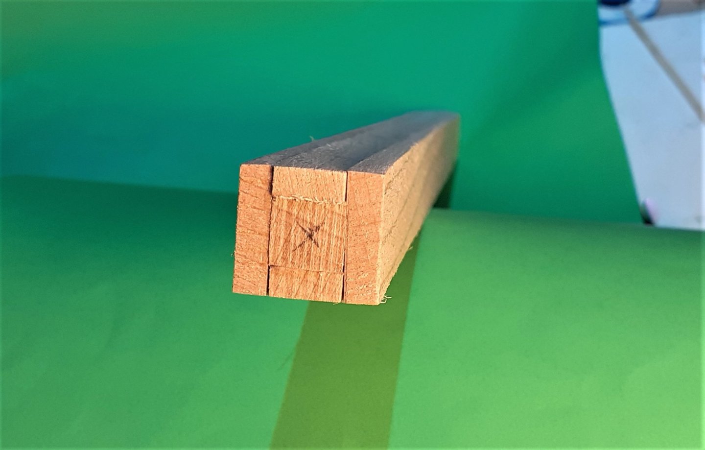
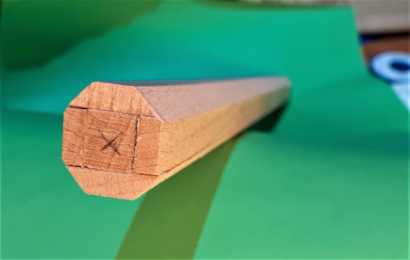
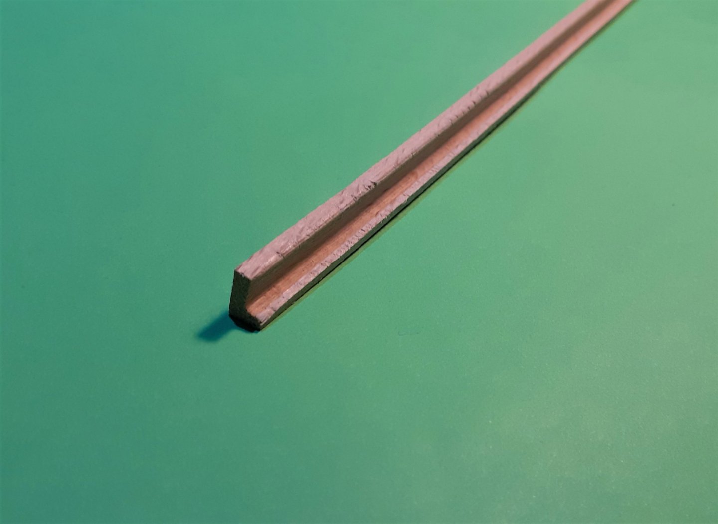
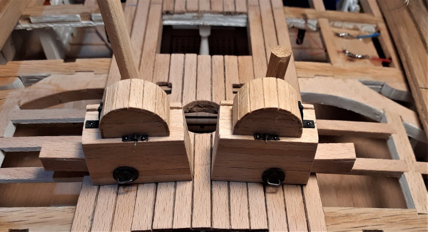
Thanks for the comment, Tom, and the others for the thumbs-ups. I wanted to be getting all the 'stuff' done for that central area around the main mast. Although the 'business end' of the topsail sheet bitts will be on the upper gun deck, the lower end of the posts originate down in the lower gun deck. These are the posts after turning the top parts and morticing for fitting to the lower gun deck and also for receiving the lower cross piece. (At this point they still had to be morticed to fit the upper deck beam.) Then morticed for the upper beam and with the lower cross piece fitted. (The morticing was done on the trusty mill.) Finished the lower brake pump head > For the pump dale I used a short piece of bamboo skewer with a hole drilled up into its centre. A test fit for the chain pump cisterns, that brake pump and the sheet bitts with a dummy blank for the upper deck beam. (Still have to make the top cross piece and the side mounted sheaves for the sheet bitts.) Now, that big hole in the centre needs something to fill it. On my other model at 1:80 I had the 'luxury' of just using shop bought dowels ~ the 'fattest' dowel I needed for that was less than 12mm (0.5 inch). The main lower for this section needs to be around 17mm. Rather than just turn a single solid piece of timber I opted for a 'made mast'. Here are the five components parts for the mast. A single square section piece for the centre and four rectangular sections (two of them wider than the other two) > The first stage of the glue-up > . . . and the second stage > In order to reduce the amount of wood that would have to be taken off at the lathe I tilted the table on the bandsaw to 45° and knocked off the corners > Just out of the lathe. While in the lathe I cut five shallow grooves to accommodate the bandings that will go there. (Using the lathe ensured that the grooves are at the same level all the way round and saves having to measure and mark later.) Still to cut the square tenon at the mast foot.


-
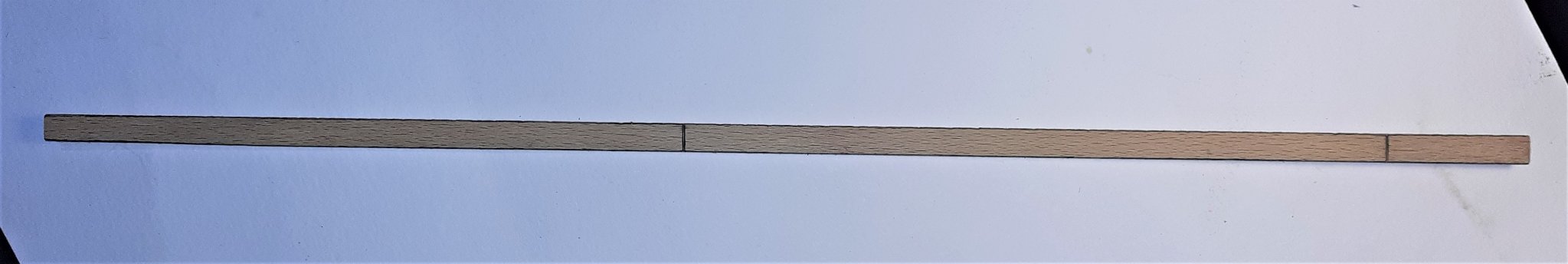
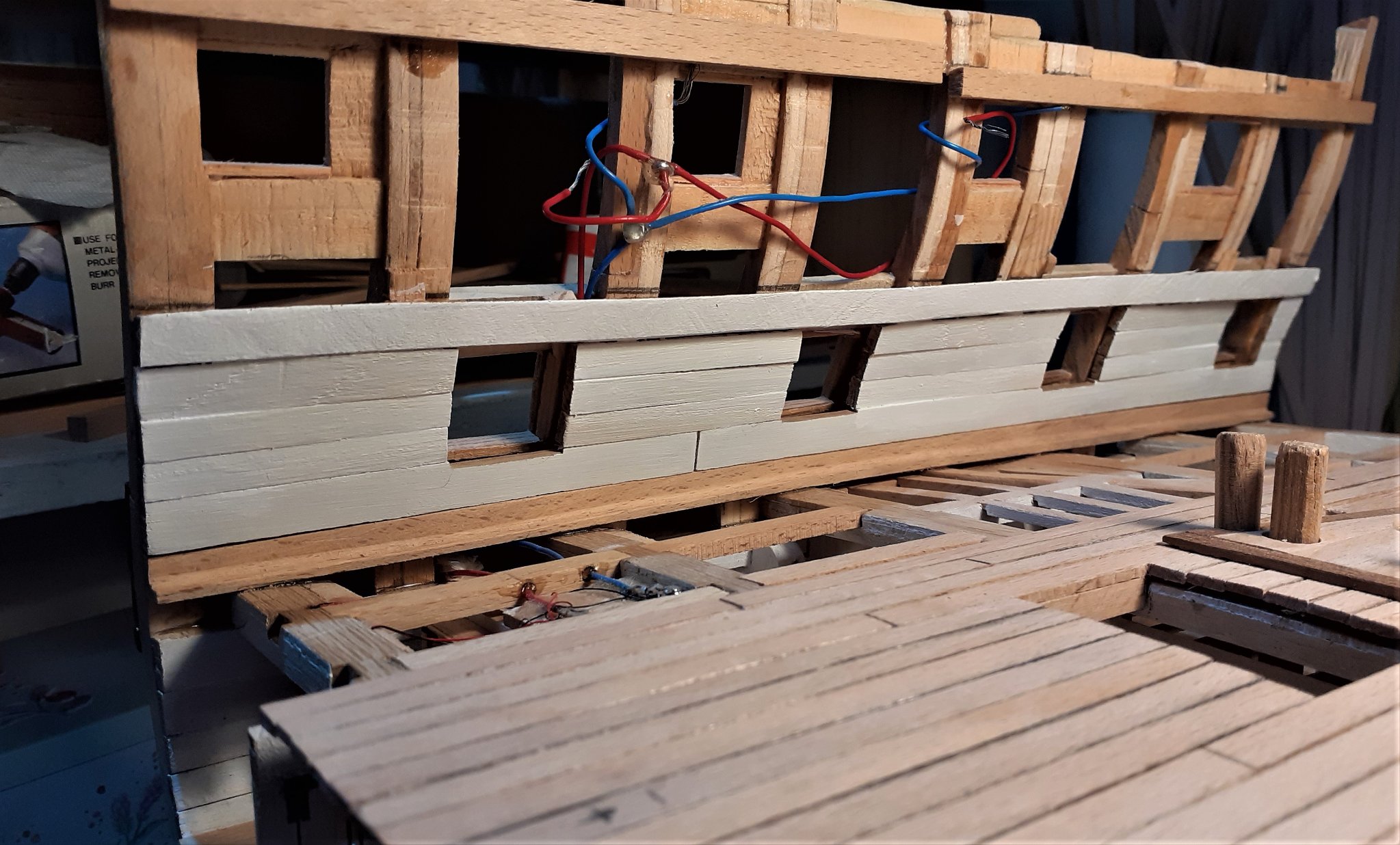
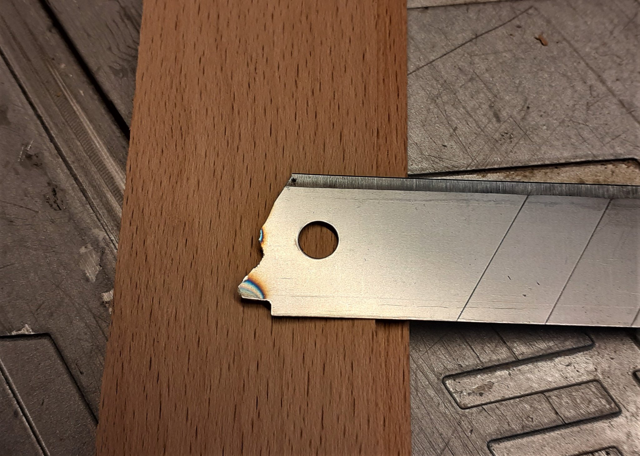
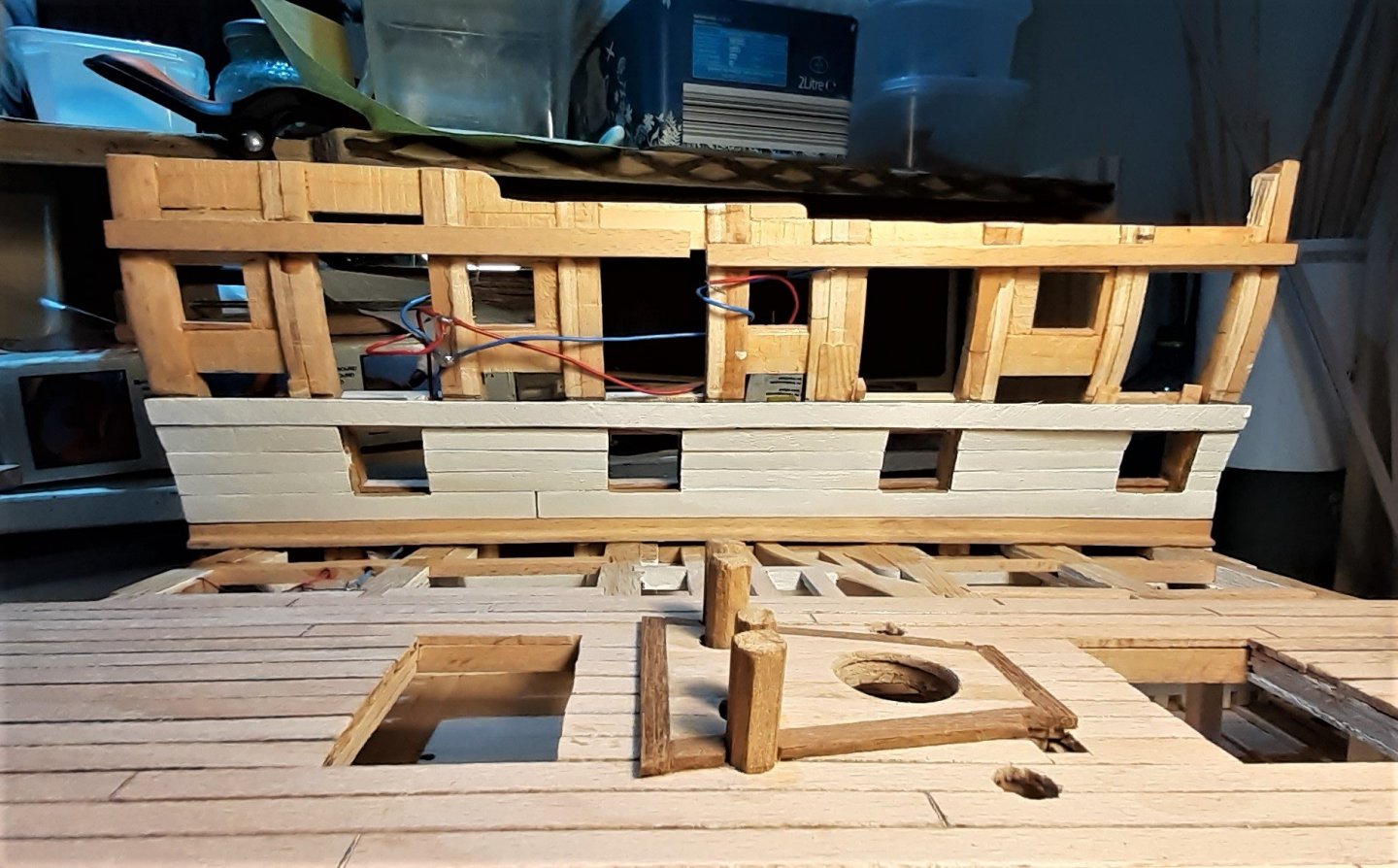
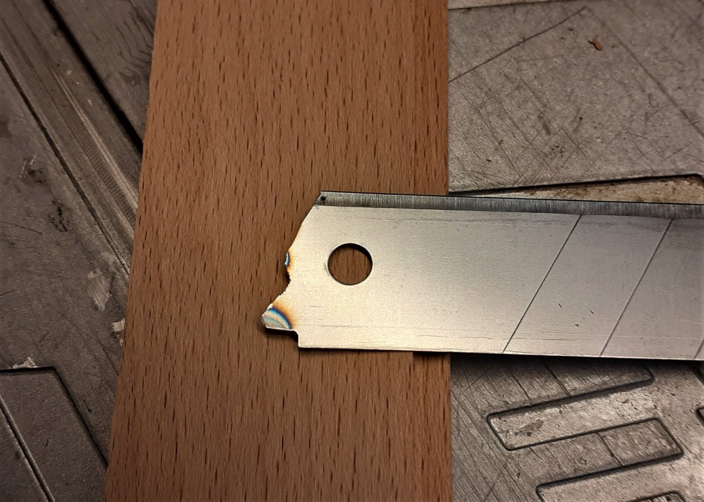
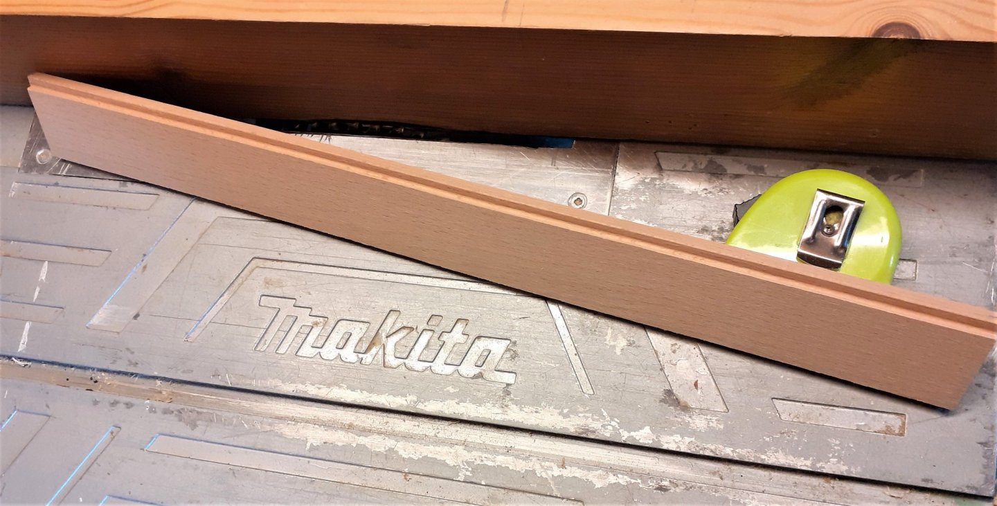
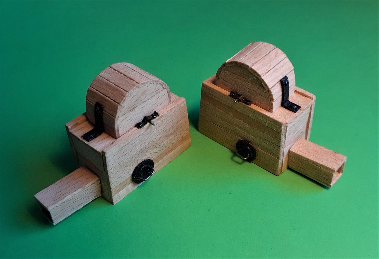
With the orlop deck more or less finished, time to move up to the lower gundeck. A whole lot of planking would have to be milled, but although quite time consuming, was fairly straightforward, while creating the profile of the waterways was something that caused a deal of frustration for me. I've never before tried using a scraper to create a moulding and it took some time before I was 'getting the hang of it'. At first I was trying to remove the required amount from a solid length of timber ~~ and that Beech is real hard stuff! It just wasn't happening for me. This is the scraper I used > That was made from a utility knife blade. As it was proving too hard to scrape the profile from the 'solid' wood, I ran it over my table saw blade to remove most of the material > Then finalised the profile with the scraper, then trimmed it down to it's final shape on the bandsaw > With these waterways done I could 'relax' and get on with doing the easy deck planking. In that central area all around the main mast it's going to be quite busy with the mast, the lower ends of the posts of the topsail sheet bitts, two brake (Elm tree) pumps, four tubes for the chain pumps along with the heads of the chain pumps. I thought "I'll just get on and make the chain pumps cistern heads." Four days later they still weren't finished! Most of the main components > . . . and glued up > The brackets at the spindles and on the top are blackened brass but the "plugs" on the sides are card painted black with wire handles. At this time the central area of the deck is planked as I want to be getting all that 'busy' stuff sorted. I also made a dummy upper deck beam so that I could gauge the approximate lengths of the brake pump tubes. The lengths of the four chain pump tubes isn't critical as they'll be covered and out of sight by the pump head cisterns. The brake pump tubes are different lengths as the one on the left of the photo (starboard side) serves the lower gun deck and the port side will serve the upper deck. I've seen drawings of 3 deckers with one brake pump on lower deck and the other one two decks above on the upper gun deck. The bottom ends of the topsail sheet bitts will be accommodated in the 2 square 'holes' ahead of the brake pumps.


- 66 replies
-
- 12
-