James H
-
Posts
6,126 -
Joined
-
Last visited
Content Type
Profiles
Forums
Gallery
Events
Everything posted by James H
-
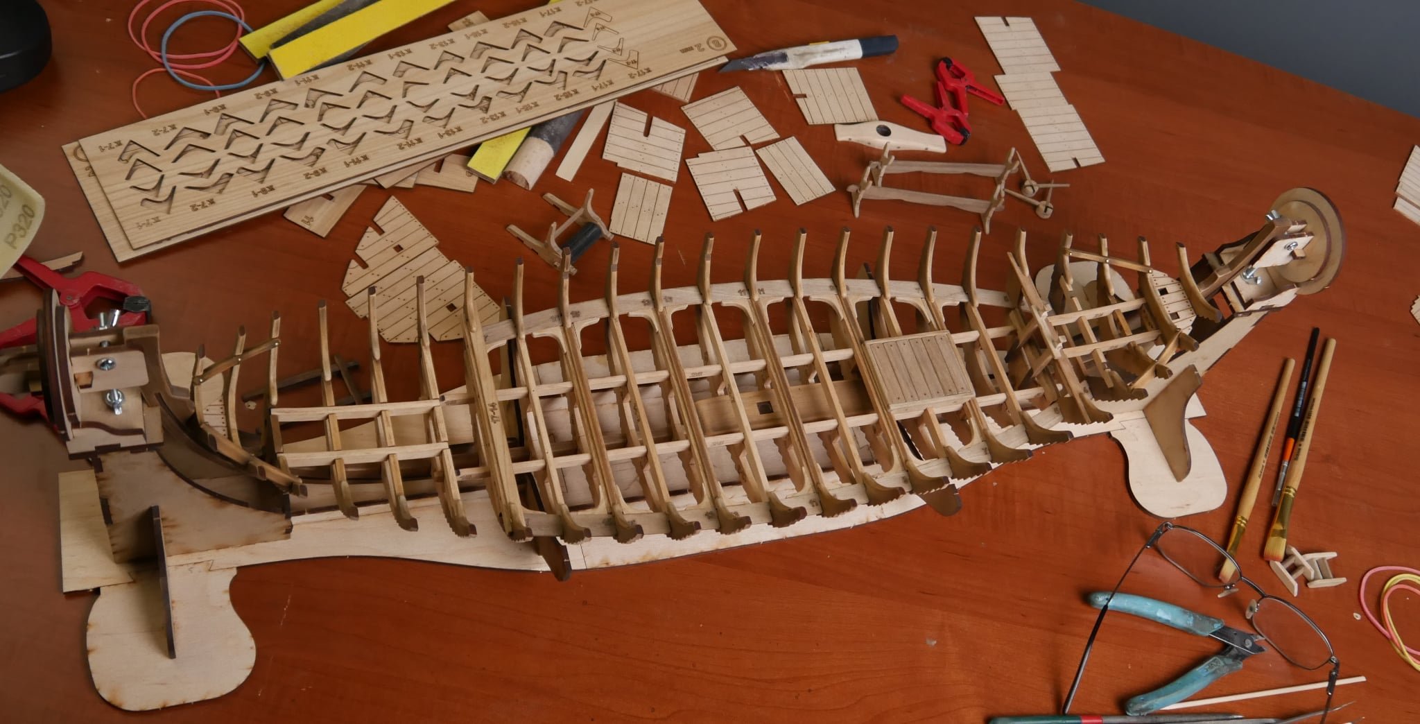
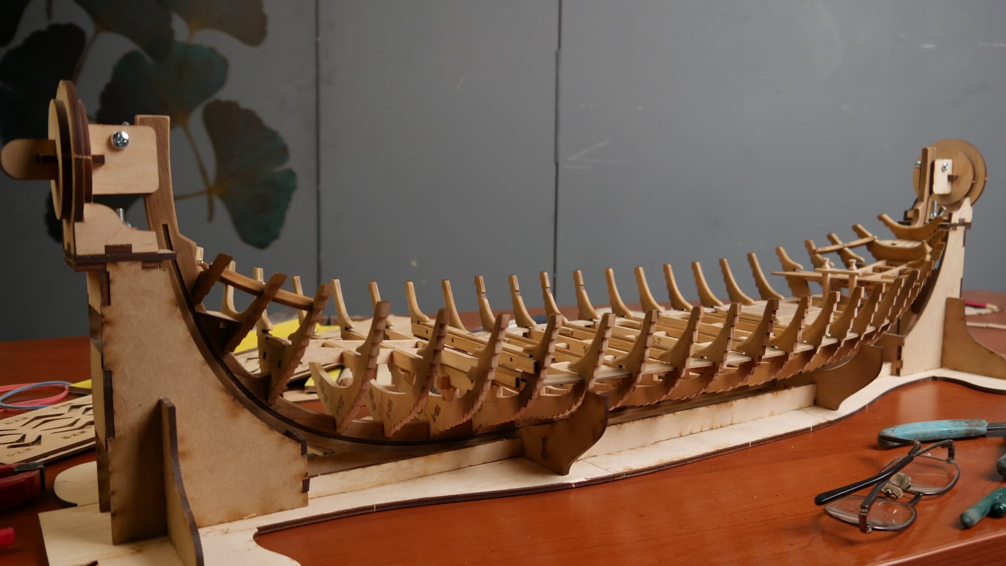
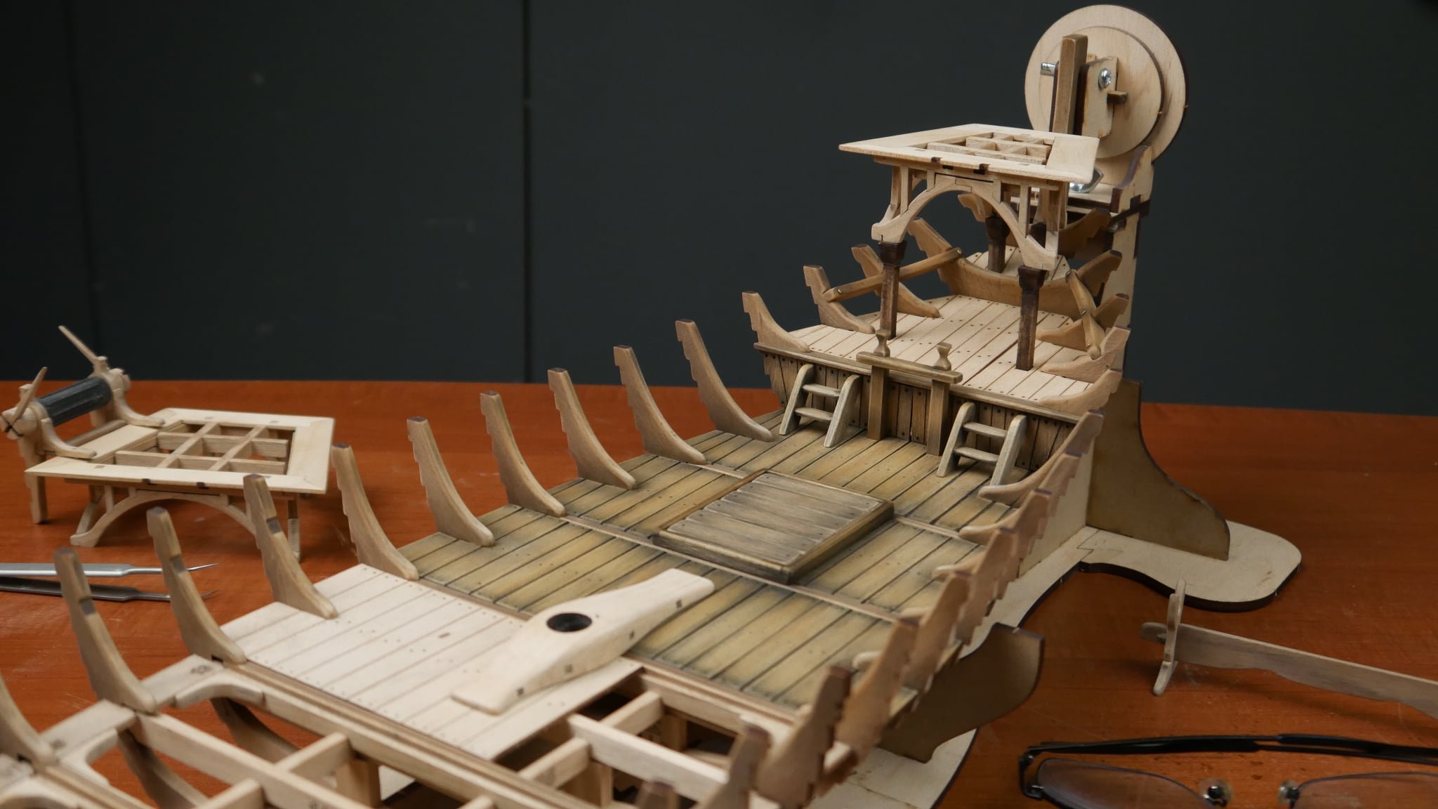
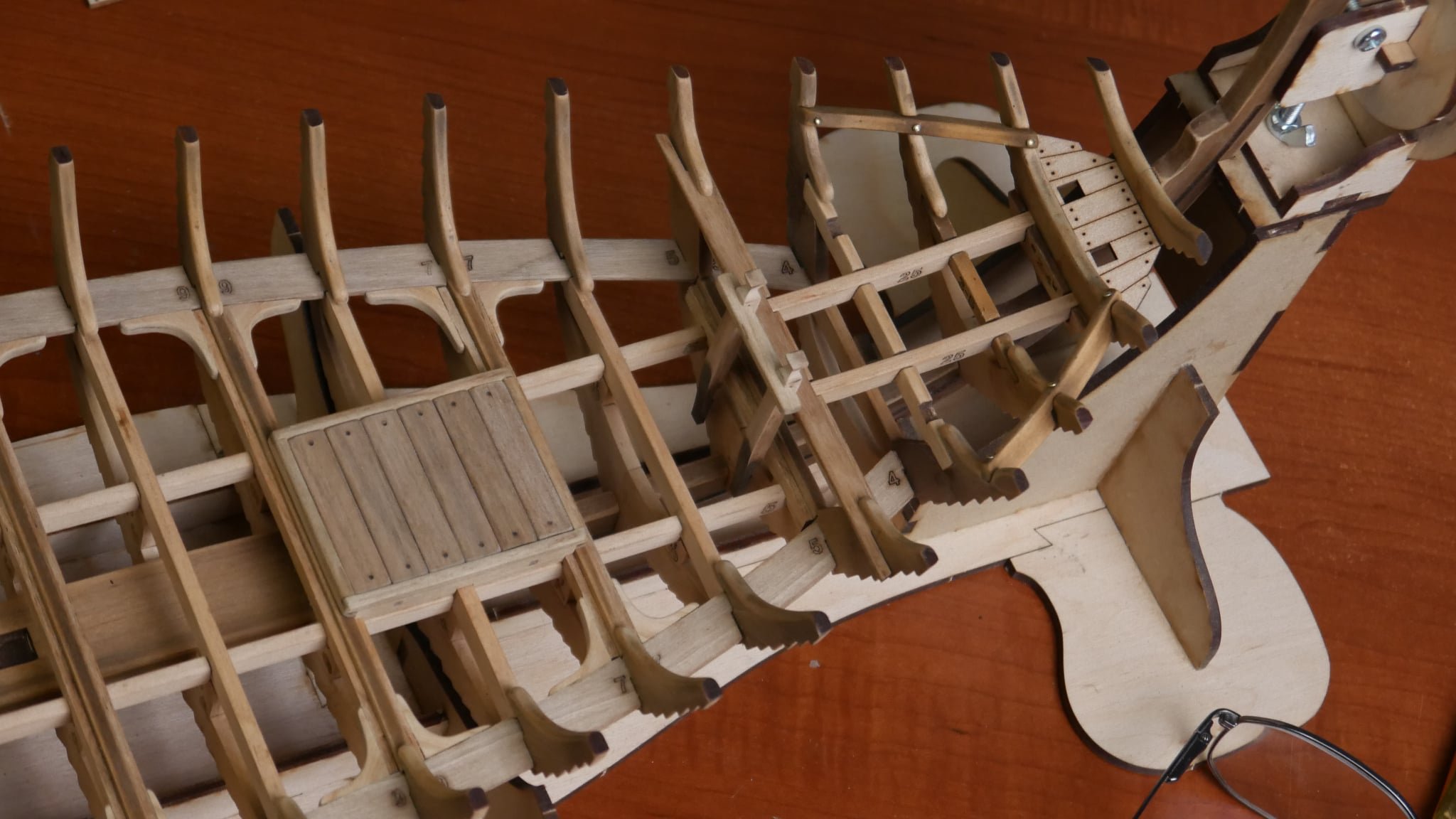
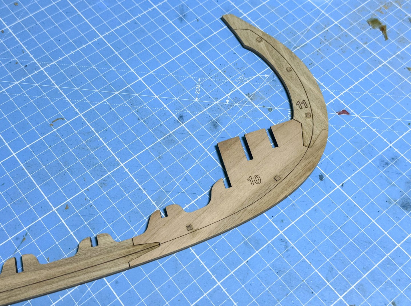
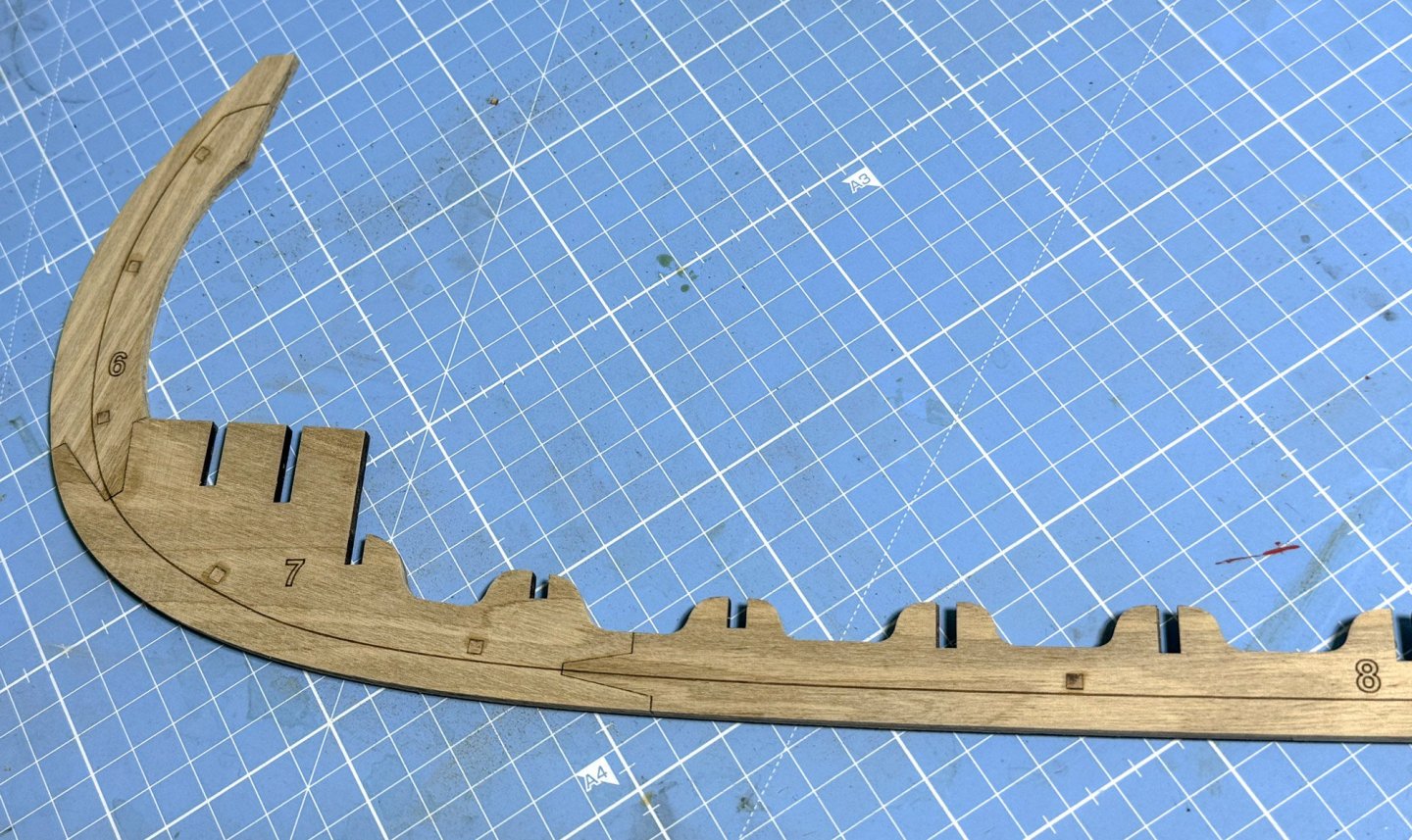
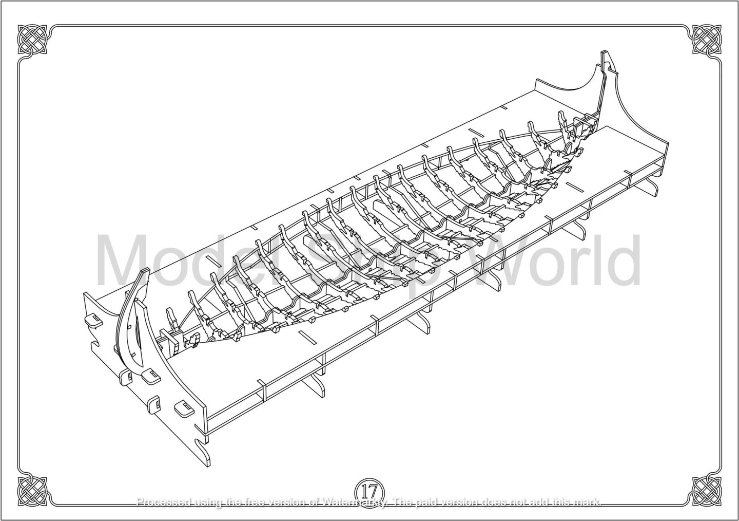
 I've spent a few days beavering away on the keel and bulkheads. The keel is made from alder, and you need to ignore the colour variation in this as you won't see it when it's all faced in quite pale walnut. There was a small variation in the length of each side, strangely, so I built the side which was more to the plan sheet and they built the second layer directly on top of that, pinning with the walnut pins as I went along. The last piece in the centre just needed a little rework at either side and it then fit in with not much of a problem. I spent a whole lot of time cleaning up the char, just for aesthetics, as you really won't see much/any of this when complete. The bulkheads, as I said, are walnut. I've never worked with walnut this pale, so that was surprising. it's like a slightly off-golden colour which doesn't really show up here. The parts fit together nicely. Some bulkhead parts just needed a little kerf removing from the joint faces, while others didn't. On parts where I could flip them over to compensate the kerf, I did so. Where I couldn't due to bevelling marks, then I used a file to reduce the kerf and make them fit. I do have to say that you barely need to remove any material to make anything fit perfectly. It's more or less just the char.
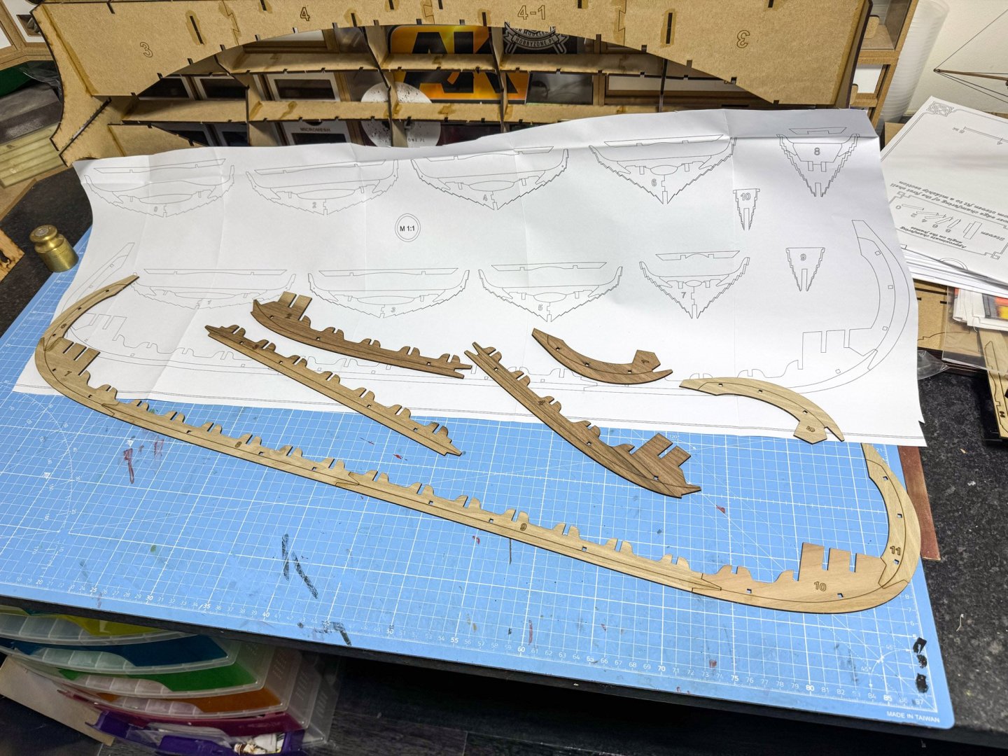
- 48 replies
-
- 11
-

-
Please can you post in ENGLISH as requested? Thanks for your cooperation- Admin
-
Fantastic work!
-
I sure did leave. I came back and the text was still there, in the test area I was going to post it. I didn't do anything that I wouldn't normally do when it comes back to post text I'd written.
-
How odd. I just tested this and left the site. I came back and went to the same place and my text was still there 🤔
-
Outstanding!
-
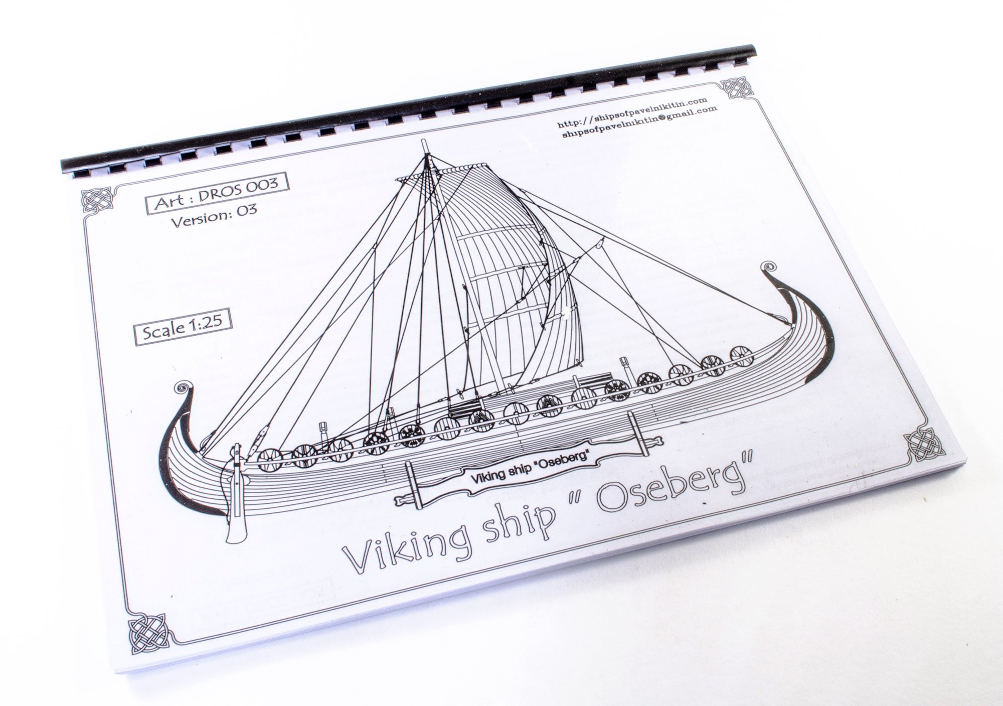
Kit review 1:25 Drakkar ‘Oseberg’ V3 - Ships of Pavel Nikitin
James H replied to James H's topic in REVIEWS: Model kits
I suspect it's based on the Oseberg design. These things were knocked together by craftsmen all over Scandinavia. I suspect no two were exactly the same.- 14 replies
-
- 3
-
-
- Pavel Nikitin
- viking
- (and 2 more)
-
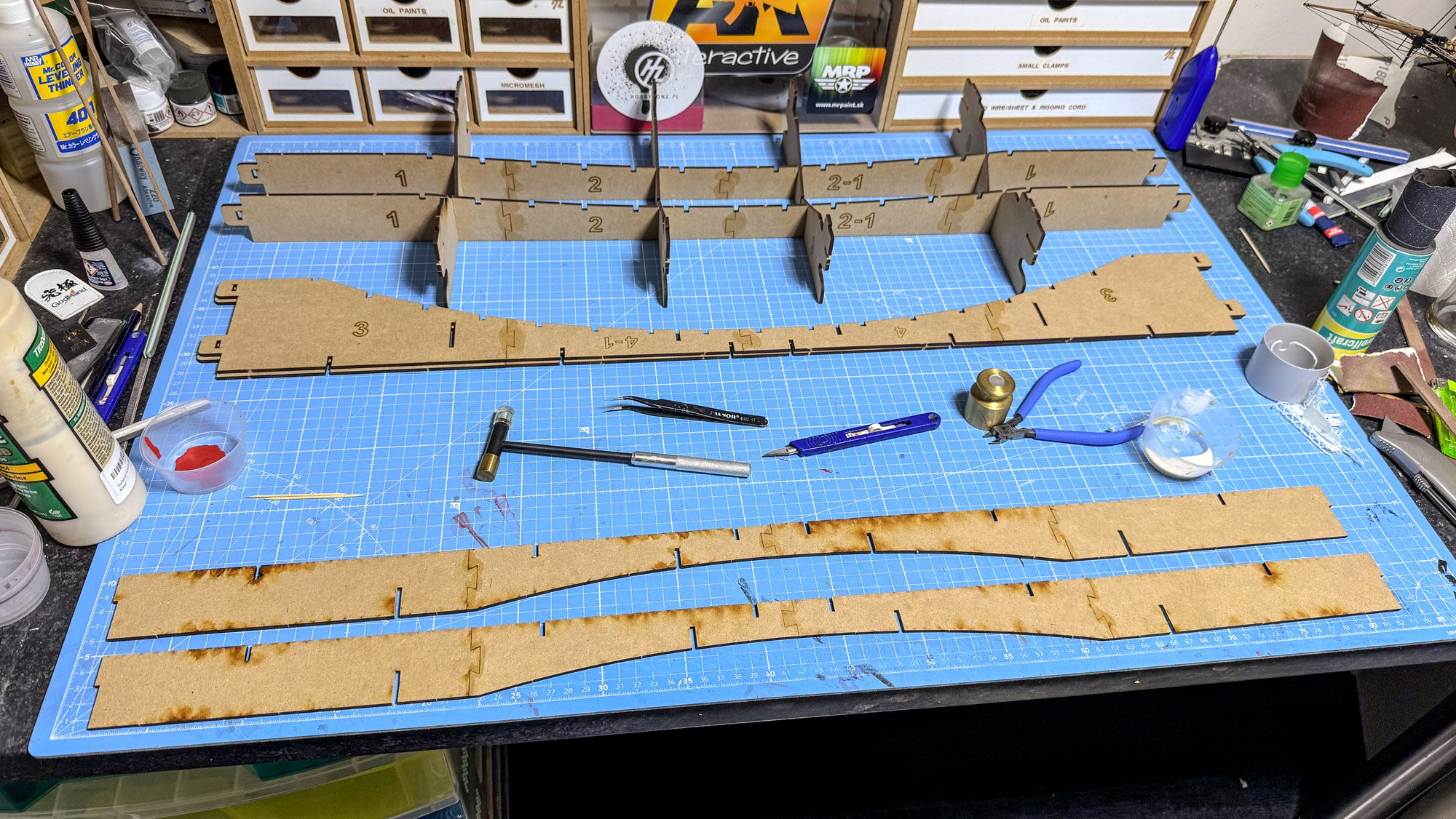
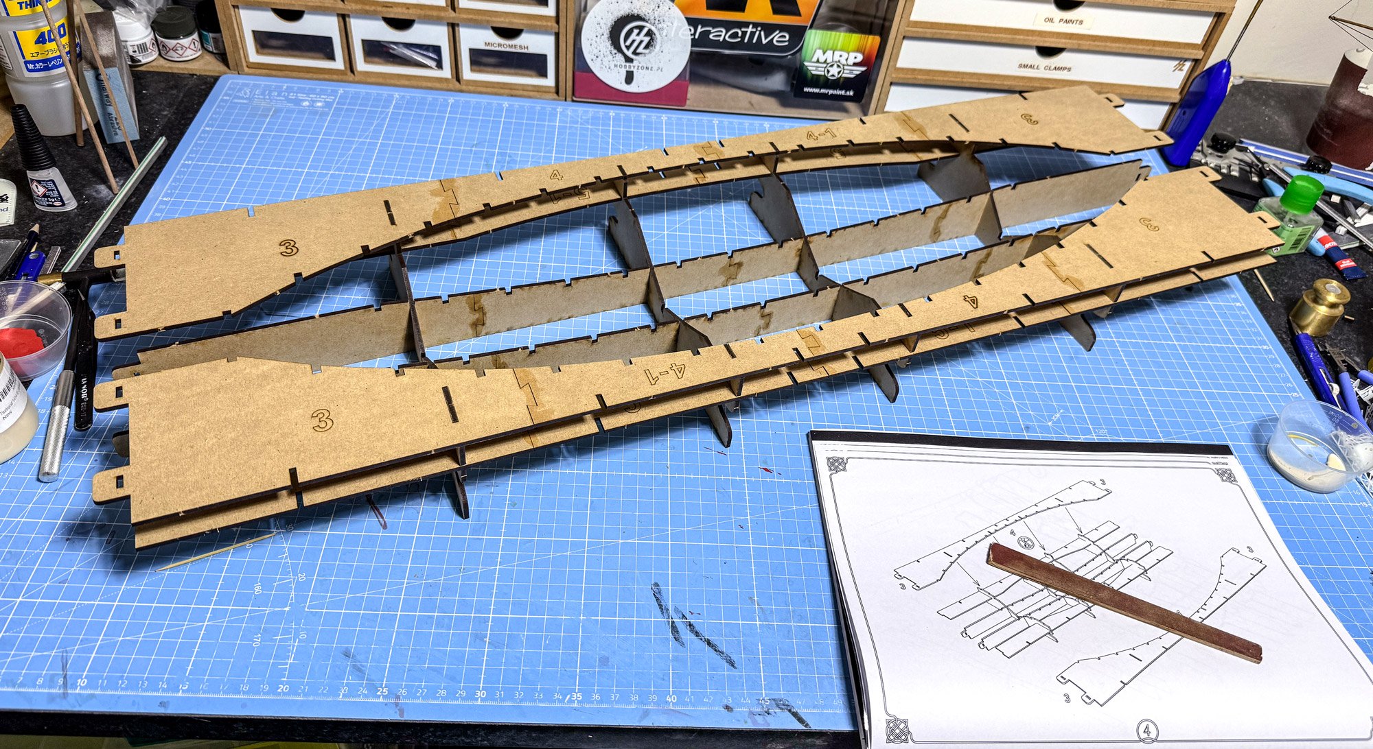
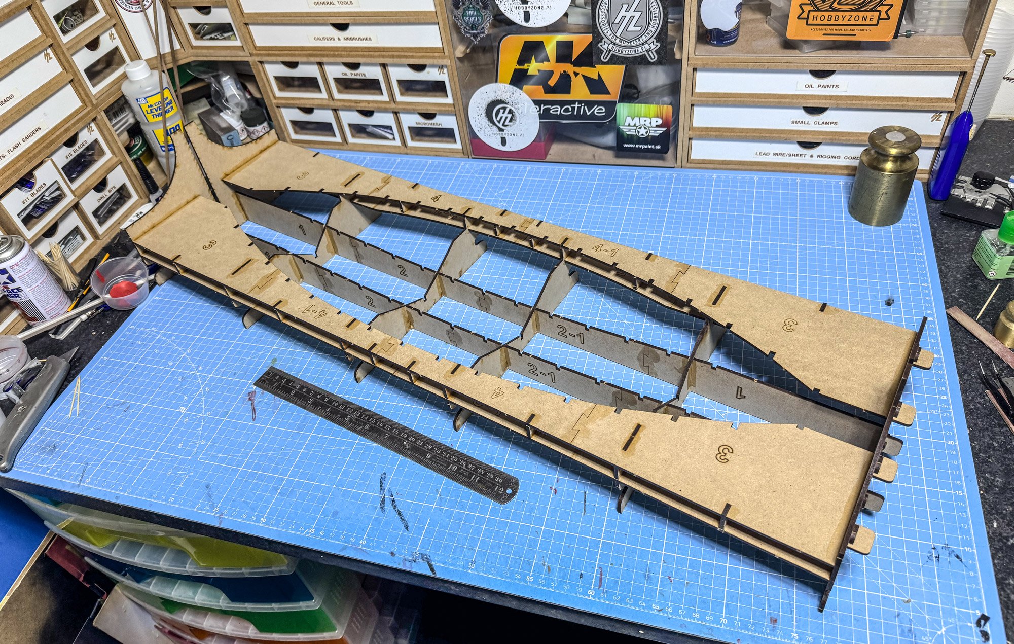
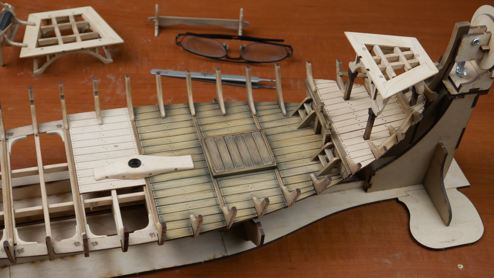
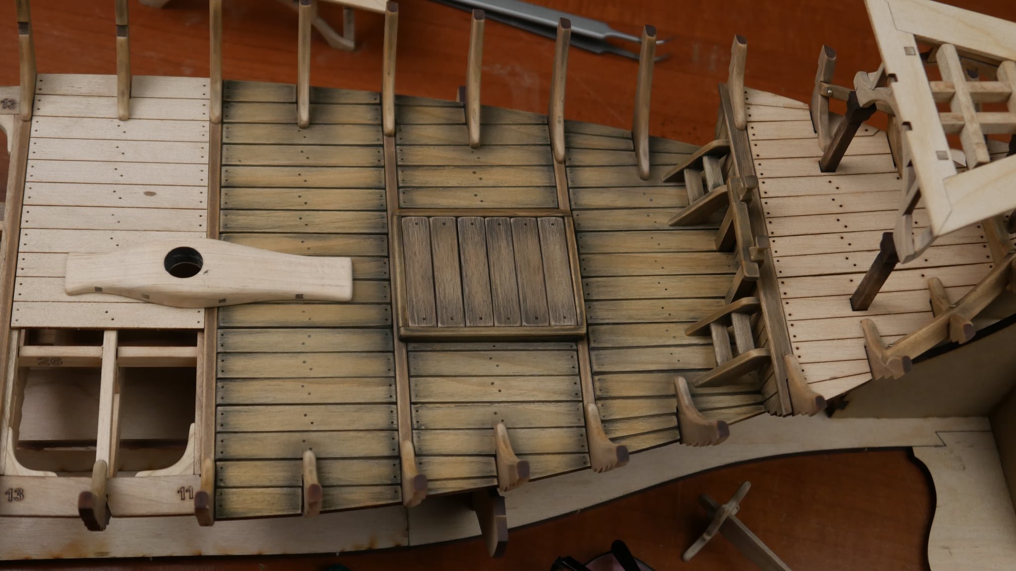
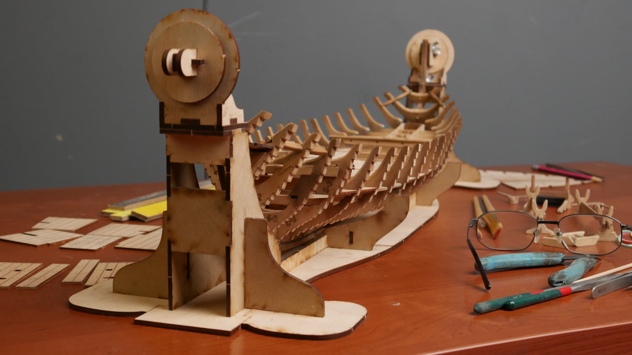
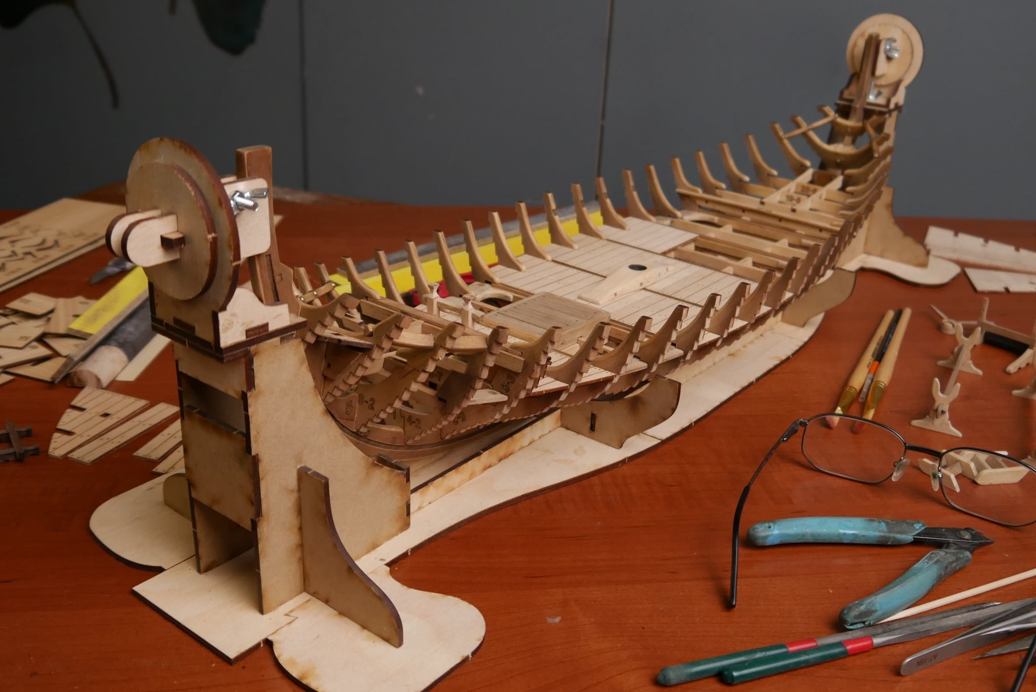
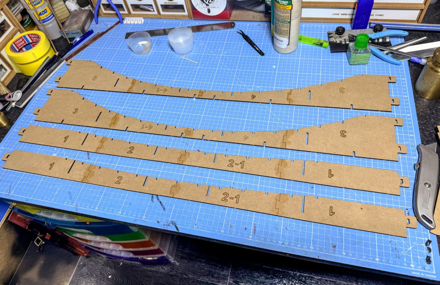
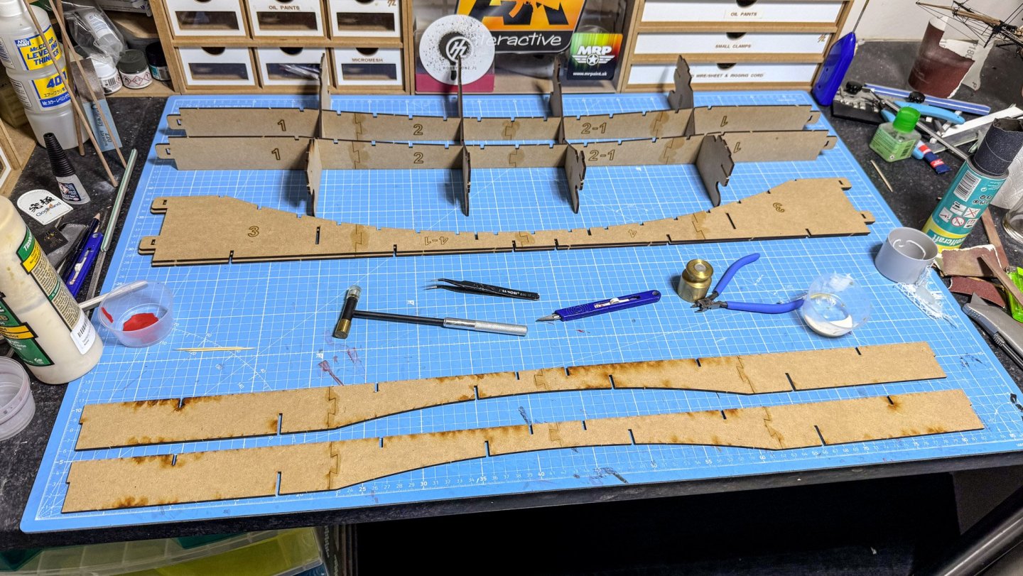
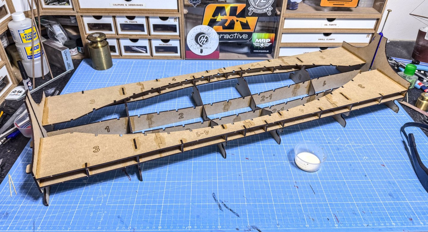
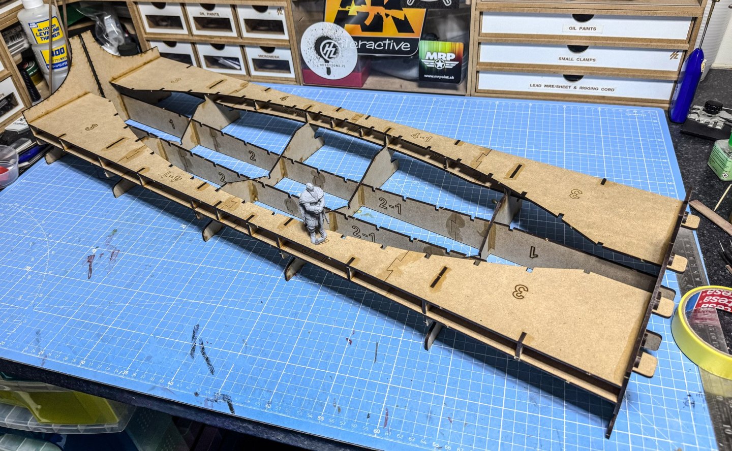
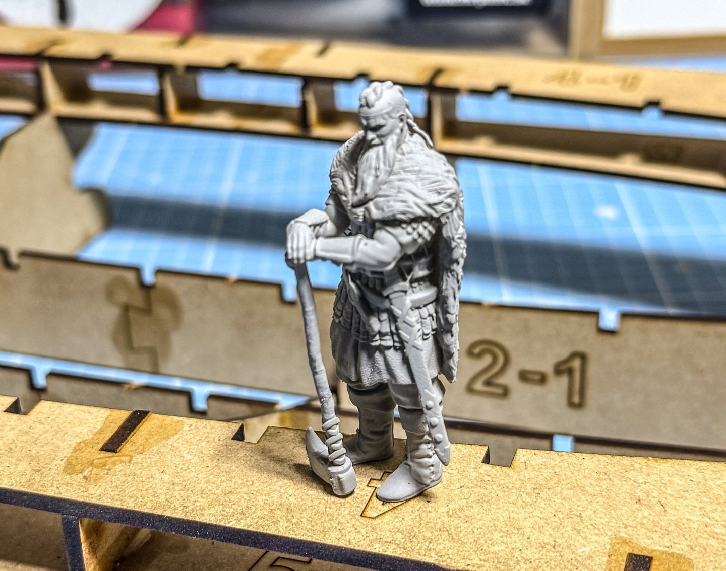
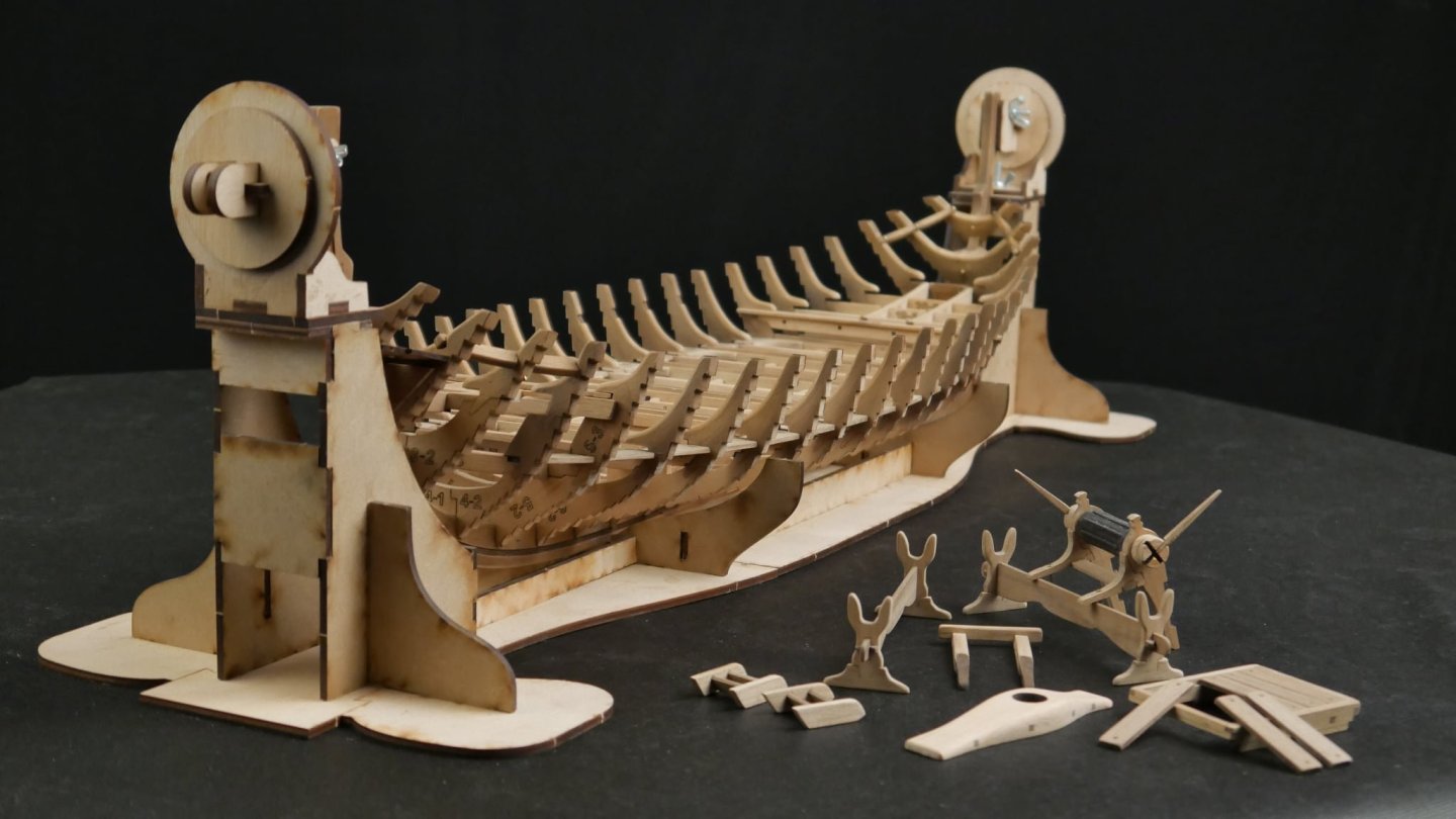
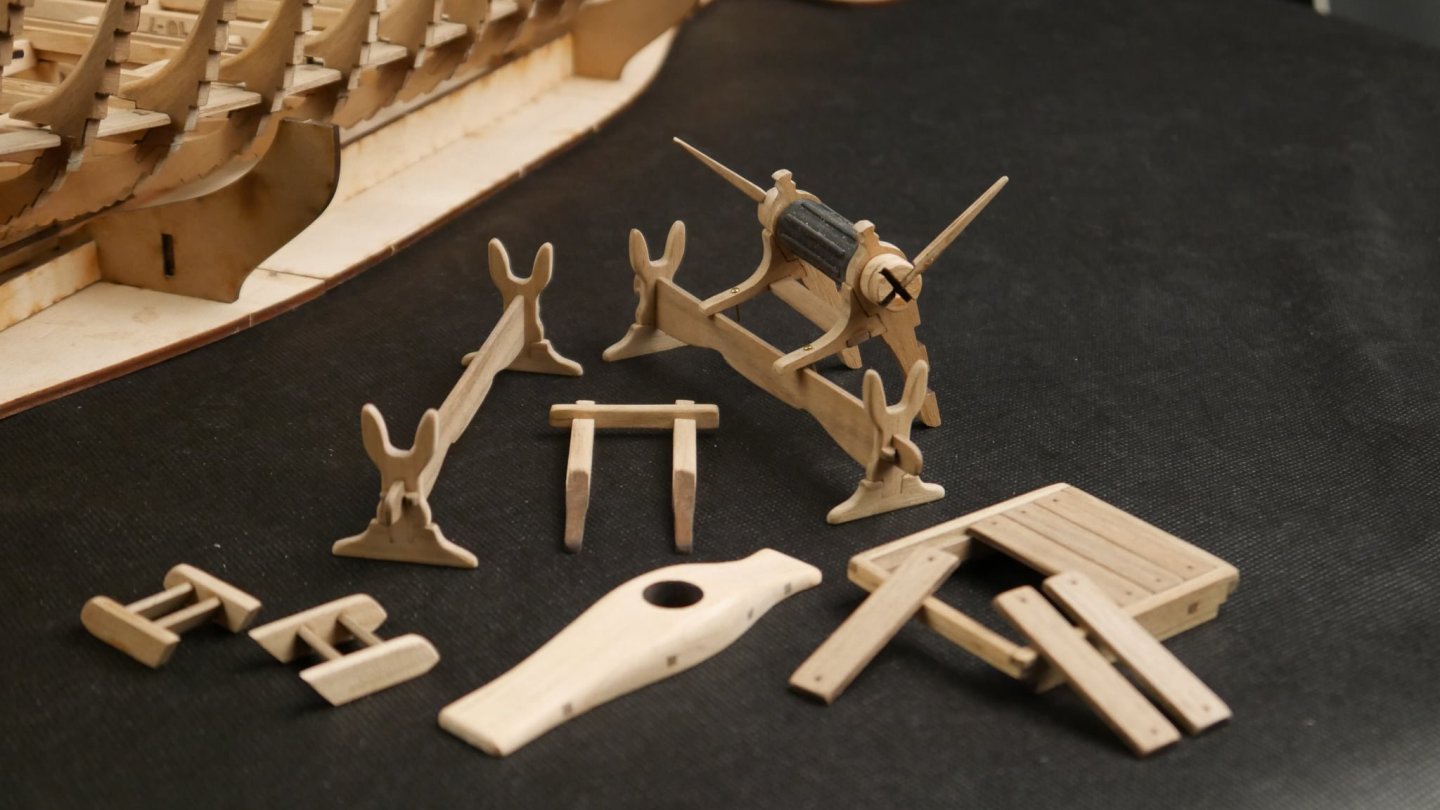
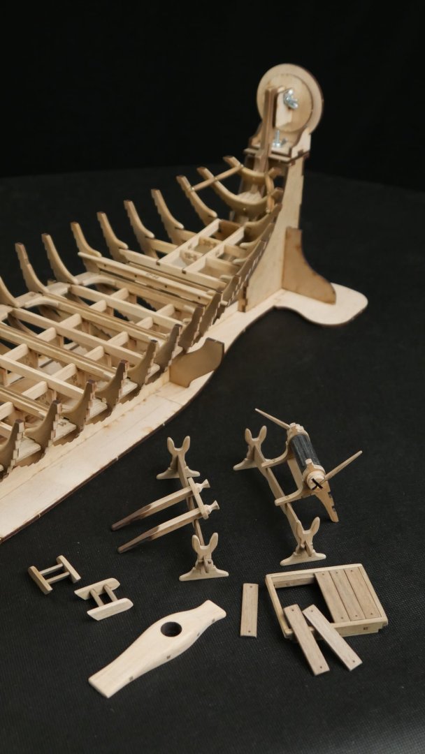
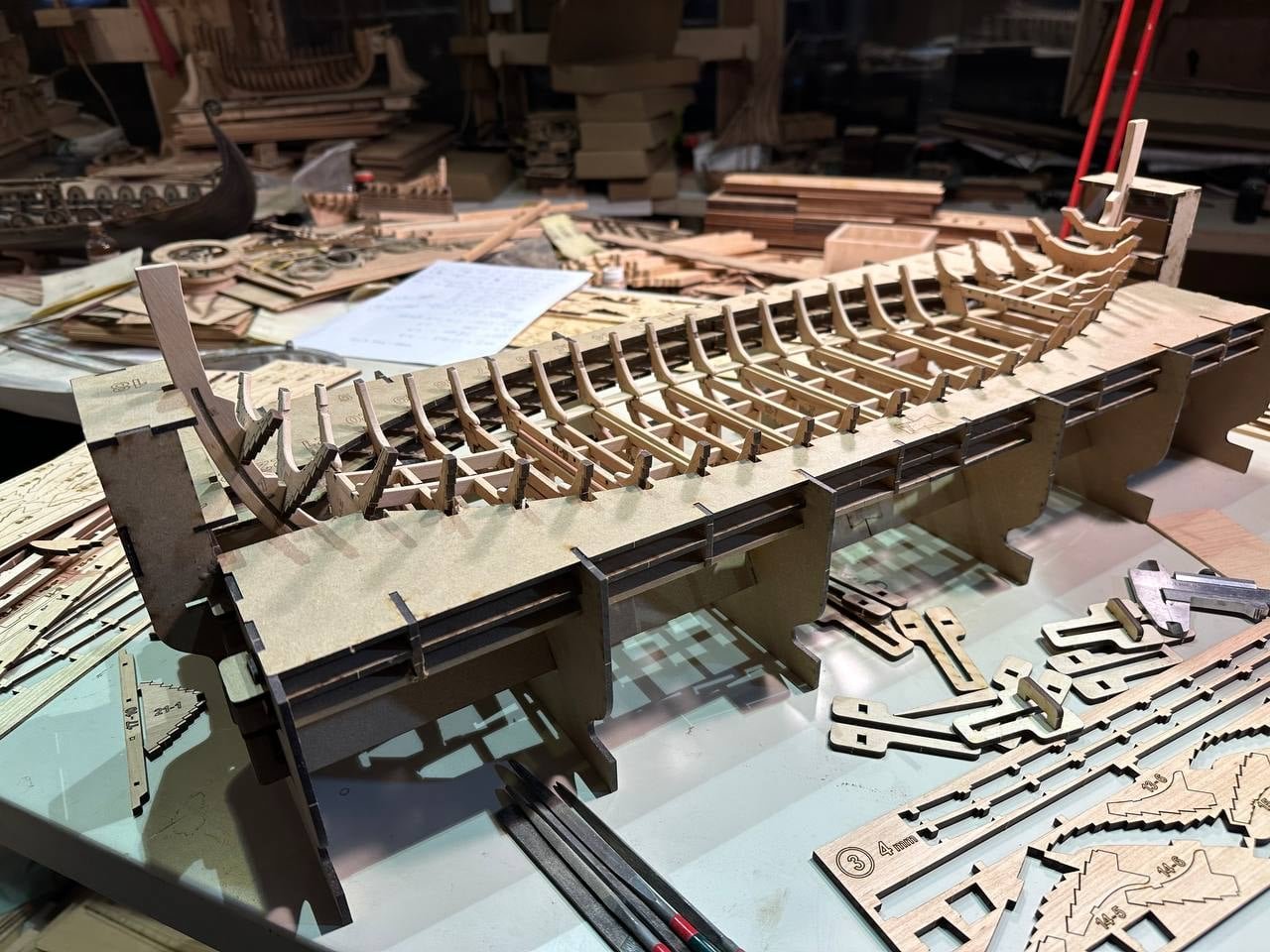
Well, I needed to build something, and plastic wasn't thrilling me too much. So, as this kit arrived fairly recently, I thought I'd jump straight in and build it. I always wanted to build a viking 'longboat' or drakkar, and this ticks all the boxes in terms of design and possibilities. I'm also planning to use the antique stain set too, but maybe leave the outer hull a little darker to semi-represent how these looked. Not sure yet, so I'll play it by ear and do some reading as I go along. I recently reviewed this kit HERE, so you can get an idea of what's in the box. The first job with this kit is to build the cradle. You really get a sense of the size of the hull when this goes together. The cradle is assembled from a few of those thirteen sheets of MDF. Construction is quite easy, but of course, it pays to take things slowly so you can ensure everything is aligned and absolutely flat on your bench, so there won't be any twists in your hull. I used a large cutting mat, sat on top of the totally flat kitchen worktops I have in my workshop. Some of the dovetail joints on the horizontal sections, were a little tight, but gentle tapping with my Amati hobby hammer with plastic head, made short work of those. I also found it necessary to remove a little char from slots. With both of these, the whole thing came together perfectly. All joint are assembled first, and then glue painted over them in the same way I do the VM hulls. My Viking overseer, Harald, has made an appearance. Ideal to show him from time to time for you to get a sense of scale. This is the figure that comes with the kit. Two heads are provided. The other has a helmet, but I didn't want that whilst he was on his ship!


- 48 replies
-
- 15
-
-

-
Kit review 1:25 Drakkar ‘Oseberg’ V3 - Ships of Pavel Nikitin
James H replied to James H's topic in REVIEWS: Model kits
I suppose it depends on how meticulous the tax office is in the recipient country. A kit can be sold at an extra cost to cover the seller's import duty and transport, but if you're in the USA, then there's currently a 25% tariff on Canadian imports. It would be cheaper to either buy direct or from Vanguard Models. (PS...No politics regarding the fact I stated, please!)- 14 replies
-
- 2
-
-
- Pavel Nikitin
- viking
- (and 2 more)
-
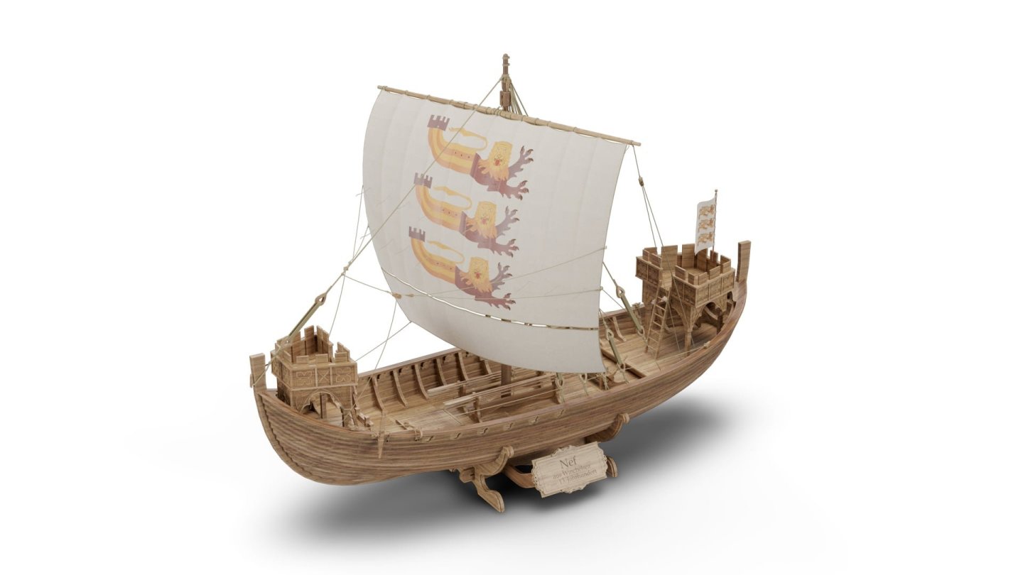
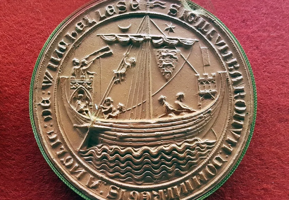
new kit alert! New kit on the horizon - Winchelsea Nef
James H posted a topic in Wood ship model kits
I've always had a thing for ships from antiquity, hence my Viking build, but the next kit from Ships of Pavel Nikitin will be the mediaeval Winchelsea Nef with a tower at both bow and stern. These things were seen commonly on English coinage and seals. This was a 13th Century vessel and will be modelled in 1:32. Can't wait to see this one!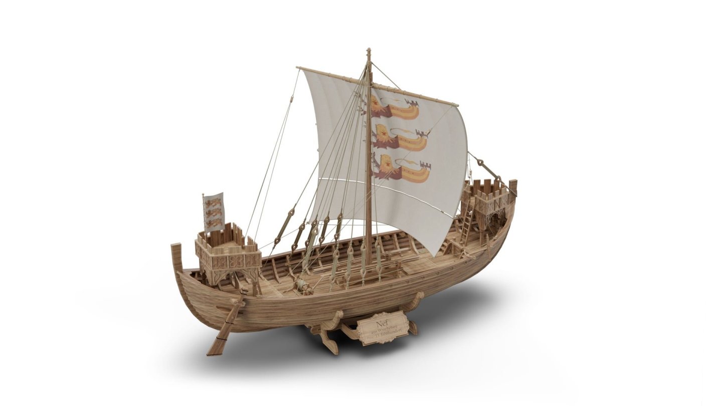


- 15 replies
-
- 21
-
-
-
- winchelsea
- medieval
- (and 1 more)
-
Kit review 1:25 Drakkar ‘Oseberg’ V3 - Ships of Pavel Nikitin
James H replied to James H's topic in REVIEWS: Model kits
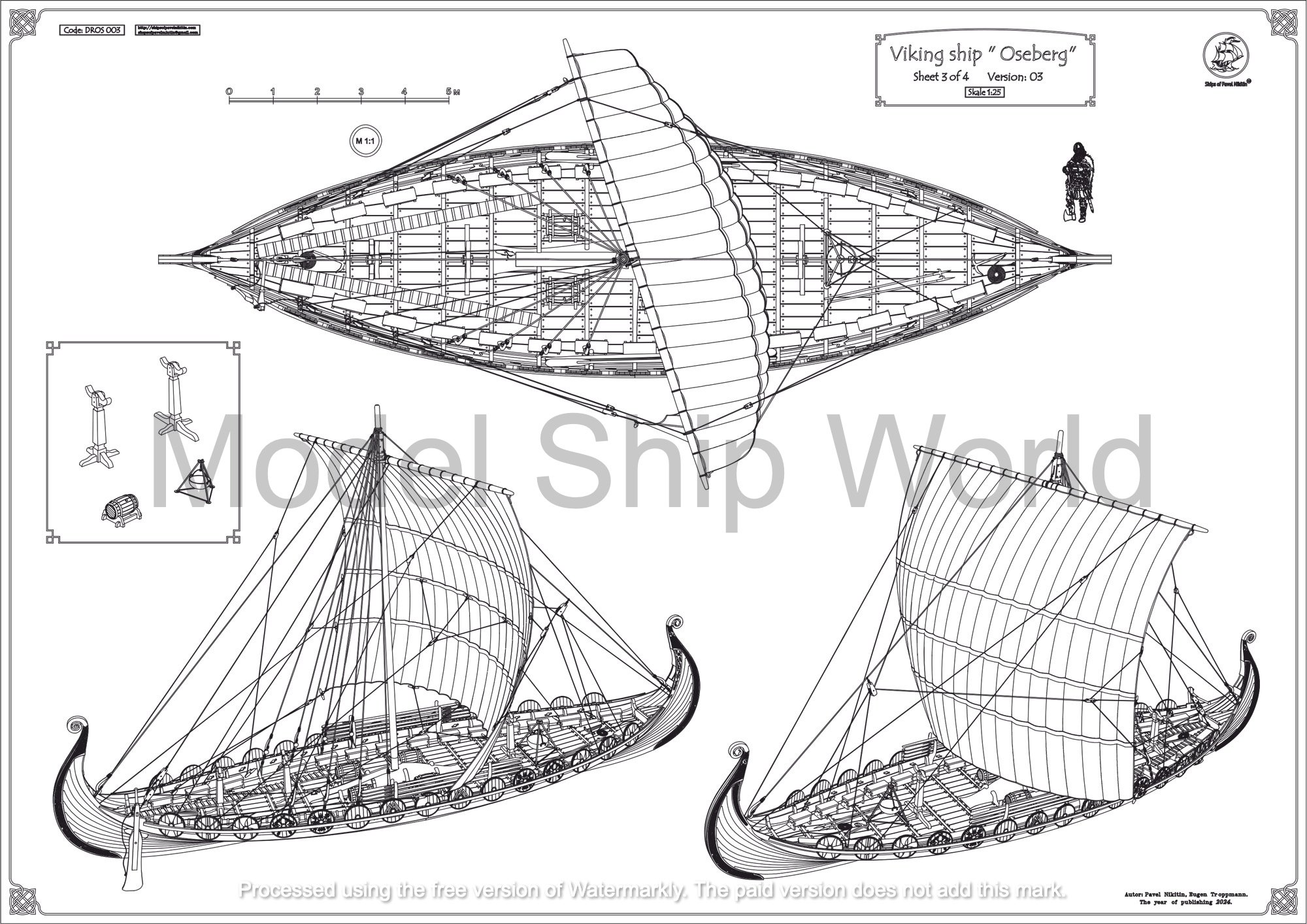
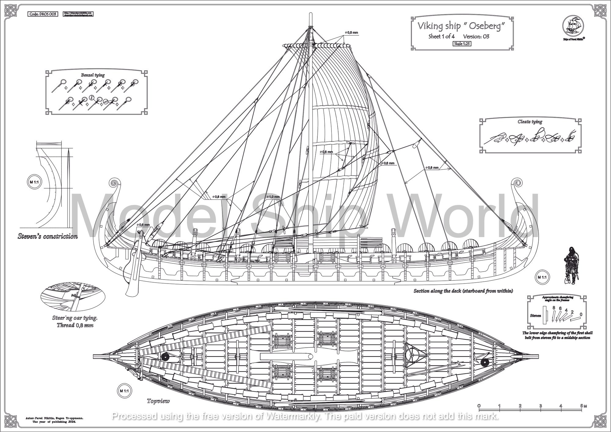
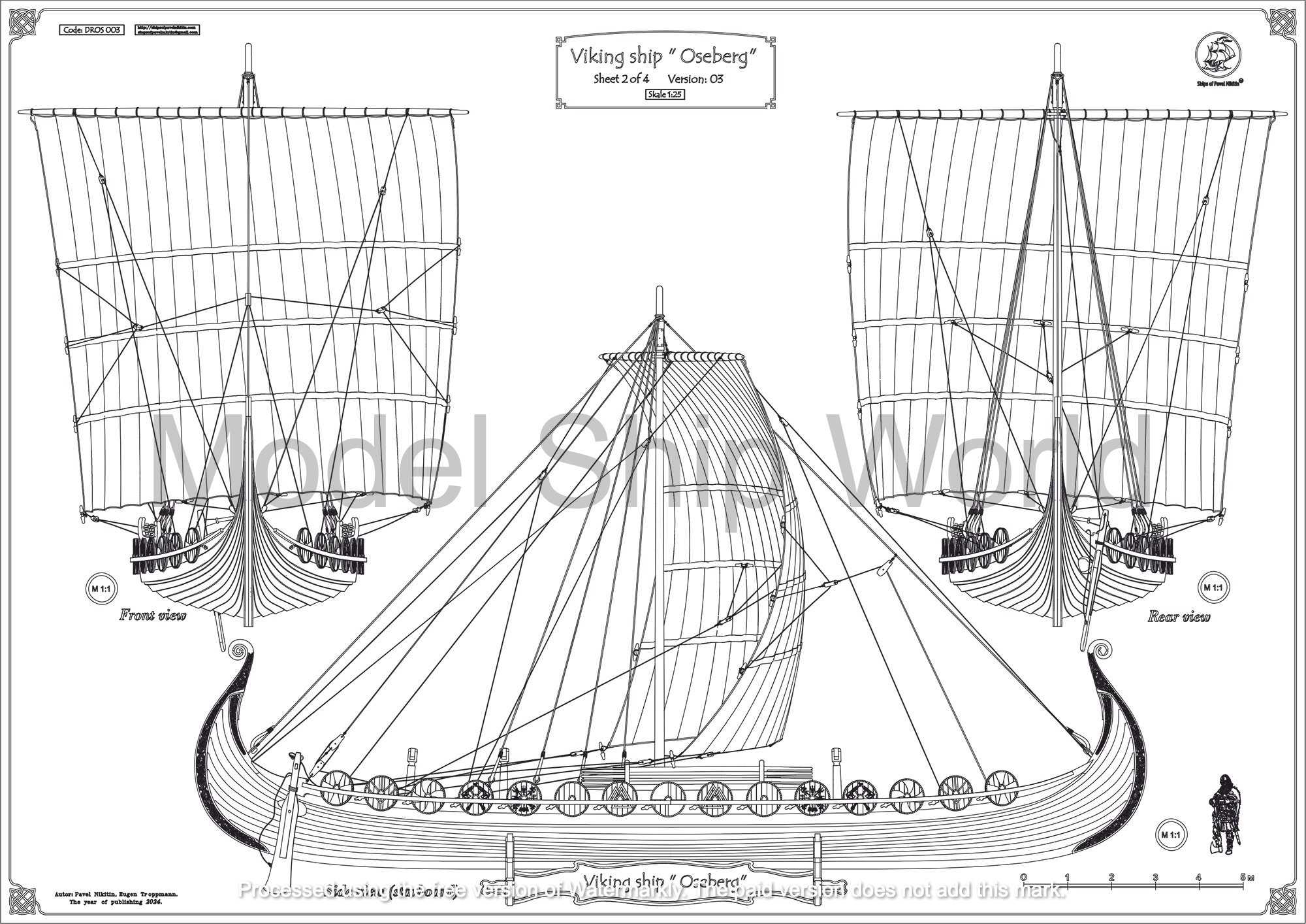
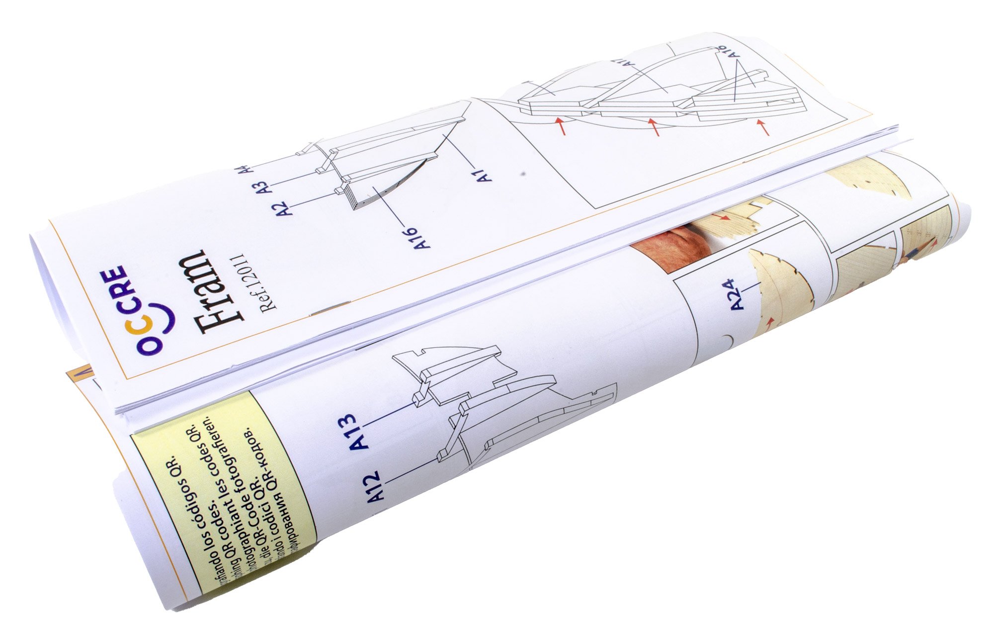
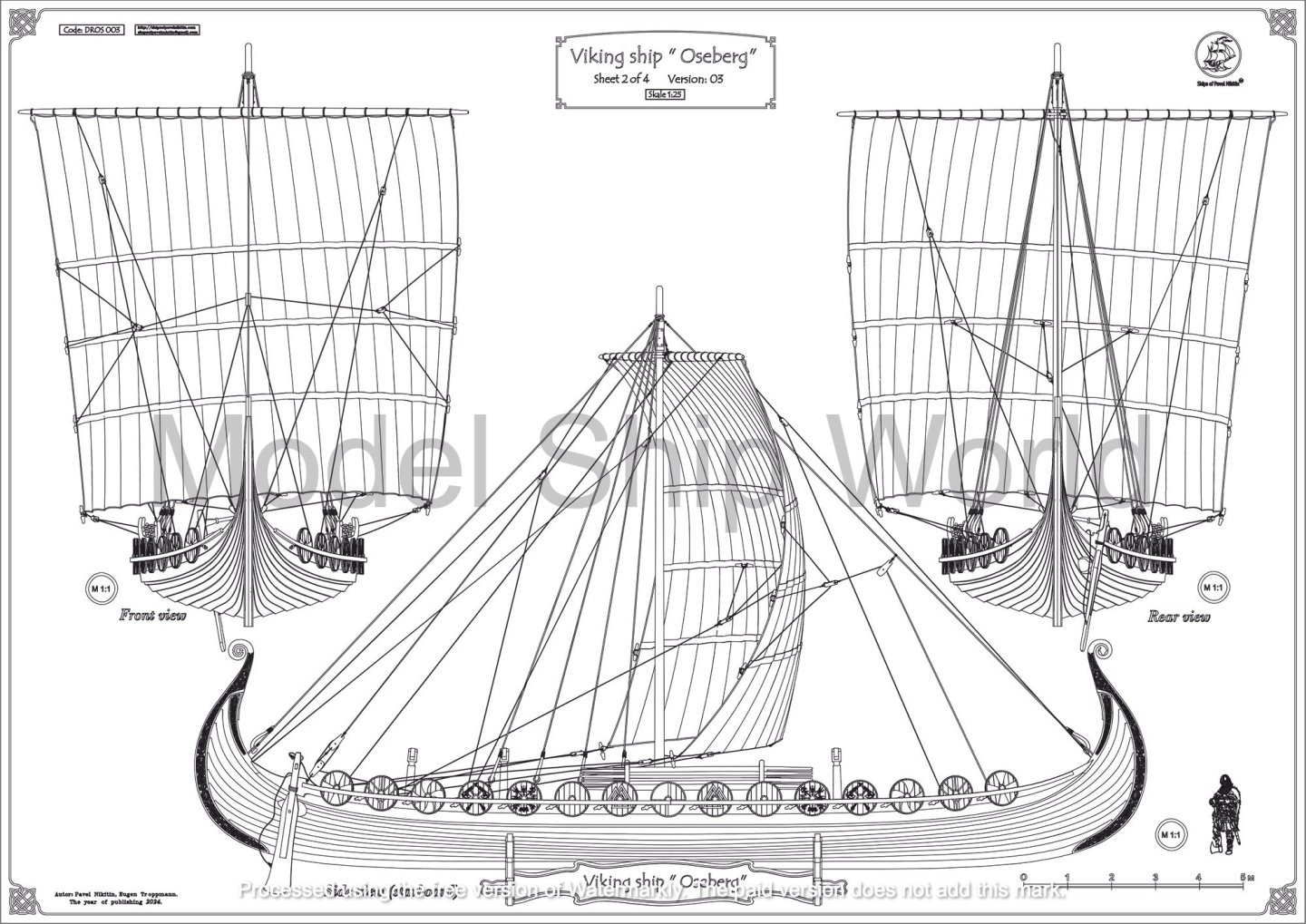
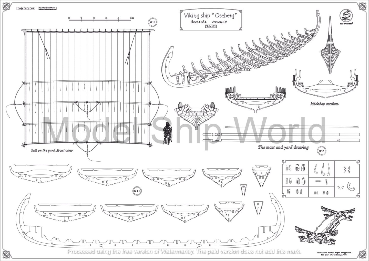
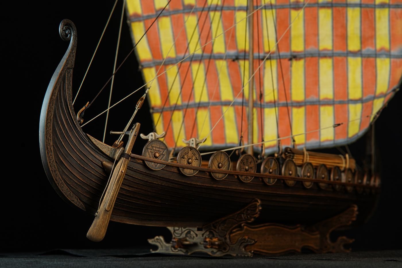
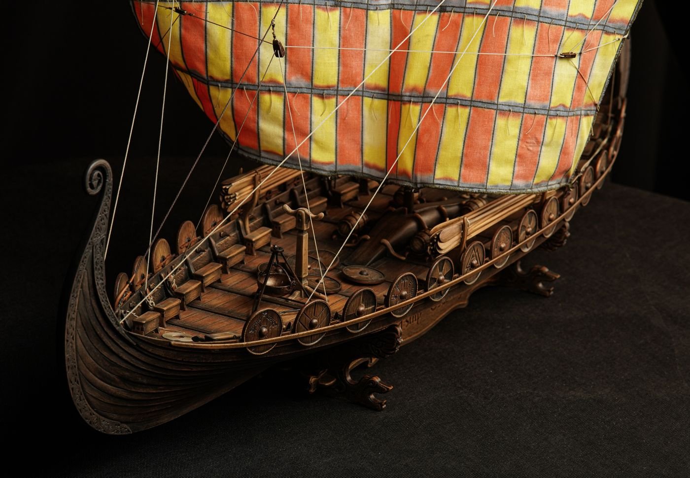
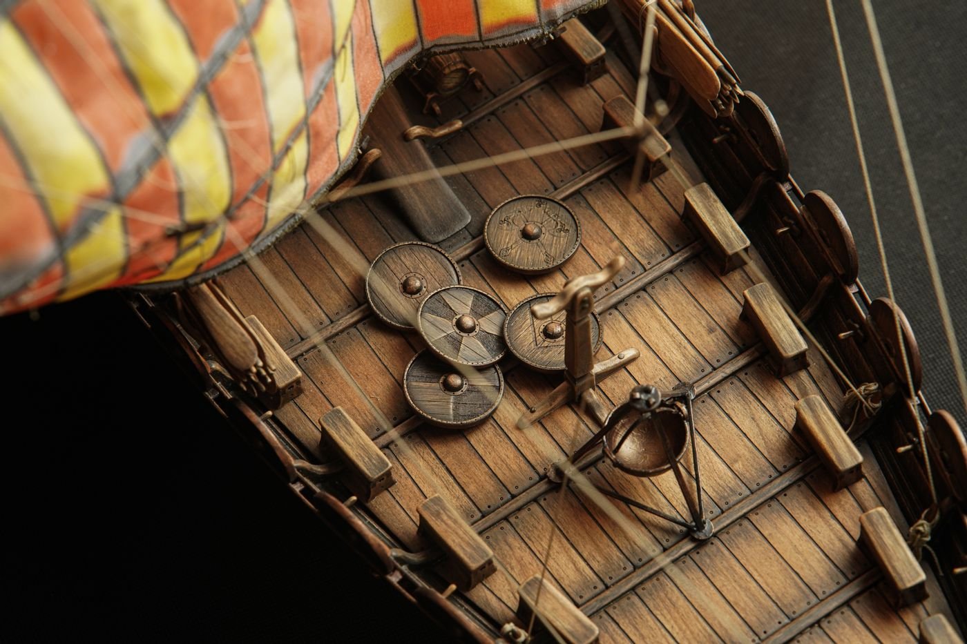
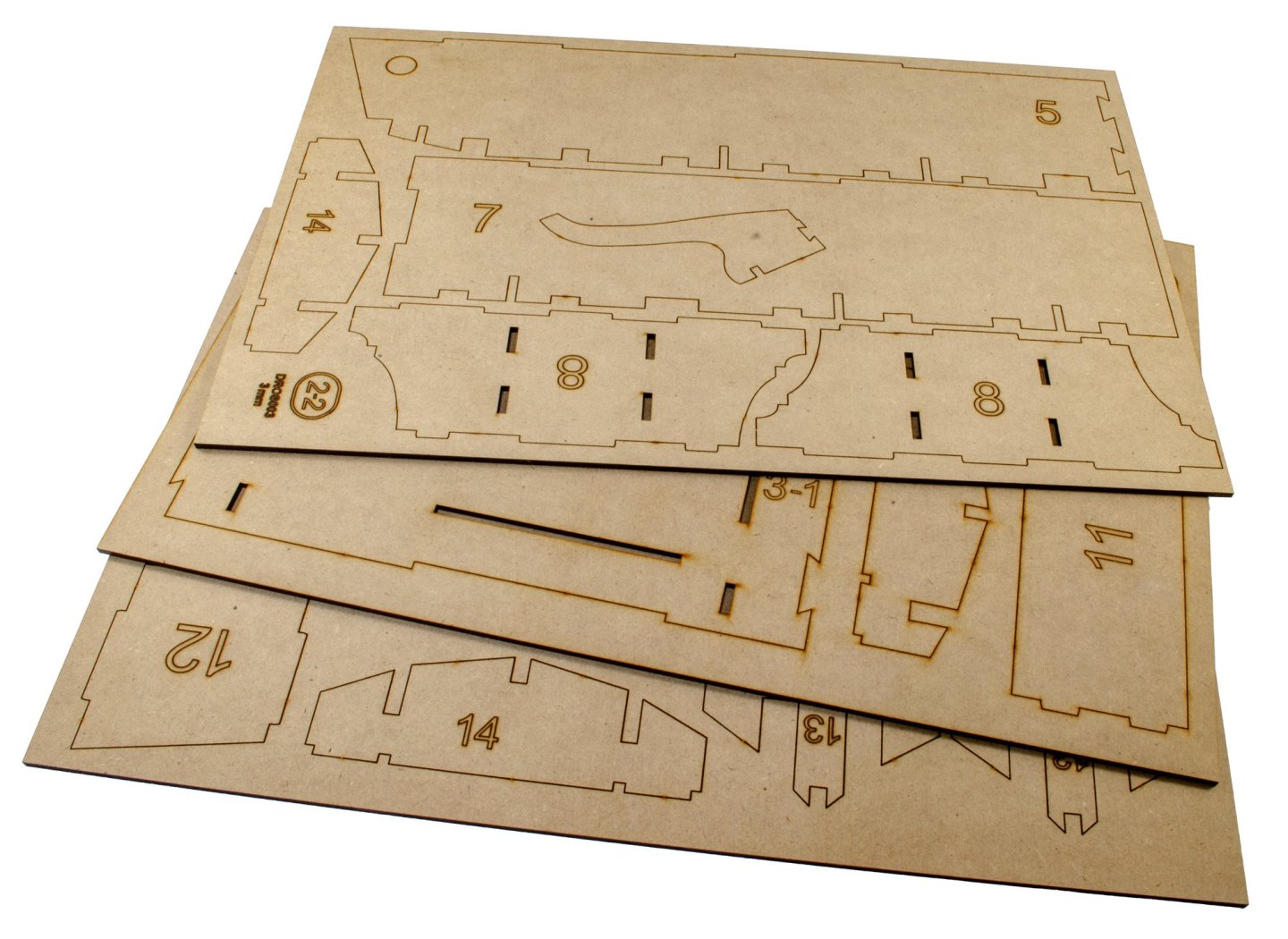
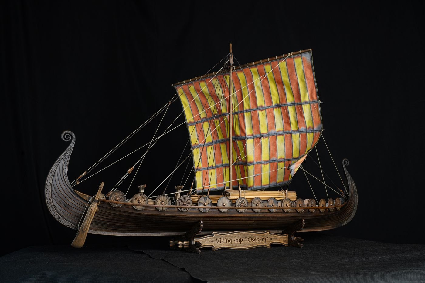
Plans: Four plans are included, at A0 in size, so you'll need a large area to open them out. Thankfully, I have those here to show you properly as digital images. These are very comprehensive, especially when you bear in mind that they also include some detail as to bulkhead construction too. Manual: A 71-page spiral bound manual is supplied, with a clear plastic front cover. All drawings are line format, but are very clear to understand. Annotation is simple to follow too, with simple symbology used throughout. An introduction in the manual states to follow the chronological steps. That sounds an easy thing to say, but trust me, there isn't much scope for variation with a kit like this. Take your time and do things in the correct order. Conclusion The v3 of this kit makes the v2 look sparse, and that was an excellent kit in itself. Having this on my bench tells me that this is more aimed at an intermediate modeller, and one who plans several stages ahead so they know exactly what to expect. If that is the case, the results will be outstanding. The quality of kit manufacture is first rate, so when you realise that these are being manufactured in a country current at war, that's something else totally. In fact, I know the manufacturing facility was very recently within 500 meters of a rocket strike! From both appearance and materials, this kit stands head and shoulders above other contemporary kits of Viking drakkar, by a very wide margin. Being based on the Oseberg remains, she also appears to be the most accurate of all of them too. The timbers used in the kit are stated as imitating those of the real vessel, which may have been the case, but the ships themselves were coated in tar and would’ve been quite dark. Pavel does sell a set of antique stains which give the model the appearance shown in the final photos. Click HERE to buy that. I suppose the final choice would be for the modeller. I would probably go for the tarred look. In all, I’m seriously impressed with this kit and Pavel’s determination to improve what already looked like the best kit available for this subject. All the small touches like the 3D shield bosses and the highly detailed laser carvings instead of the usual white metal fayre, really sets this apart. If you’ve ever had a thing about Viking ships or just want to build something a little different, then I really recommend this new release. My sincere thanks to Pavel Nikitin for sending this kit out so quickly under current circumstances. To buy directly, click the link at the top of this article.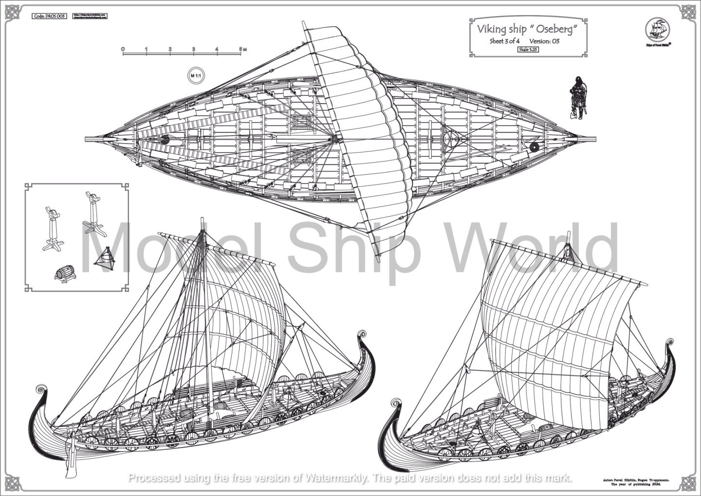


- 14 replies
-
- 16
-
-
-

-
- Pavel Nikitin
- viking
- (and 2 more)
-
Kit review 1:25 Drakkar ‘Oseberg’ V3 - Ships of Pavel Nikitin
James H replied to James H's topic in REVIEWS: Model kits
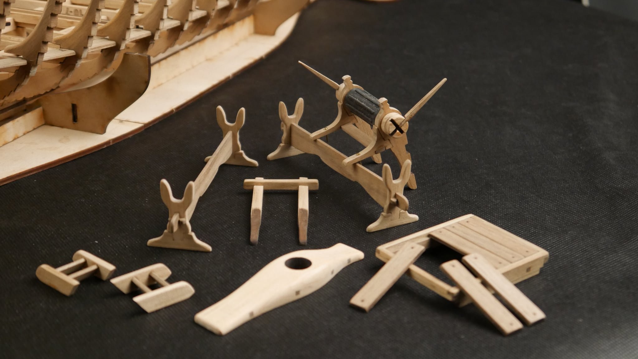
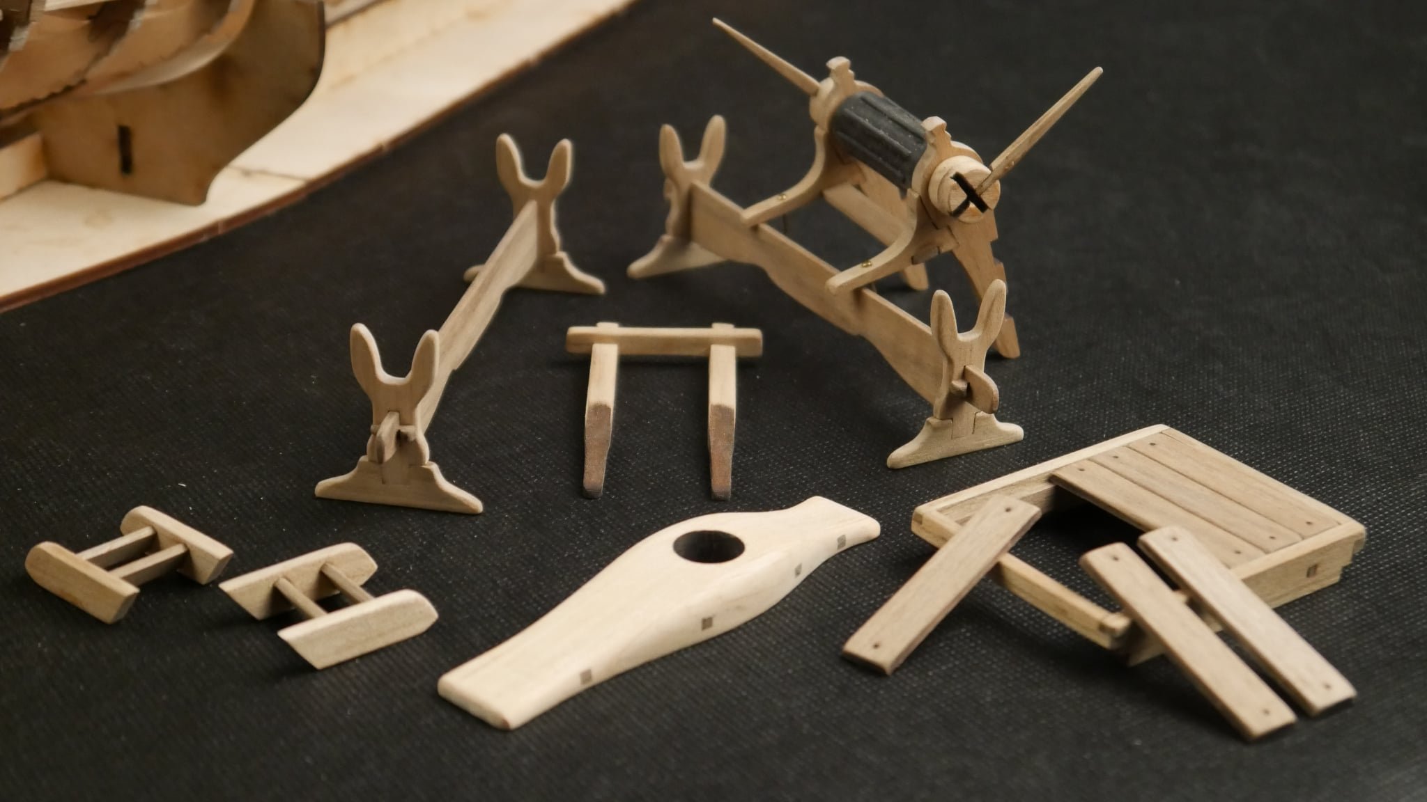
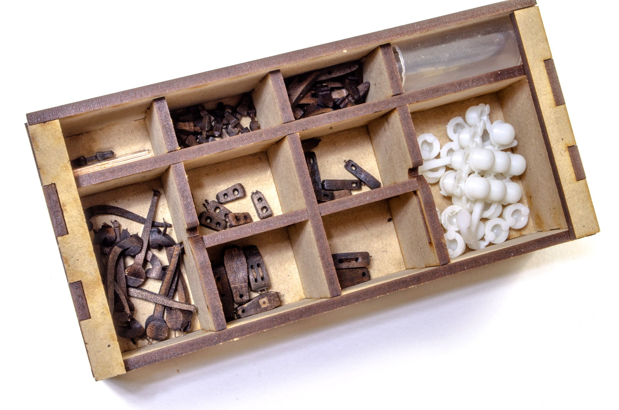
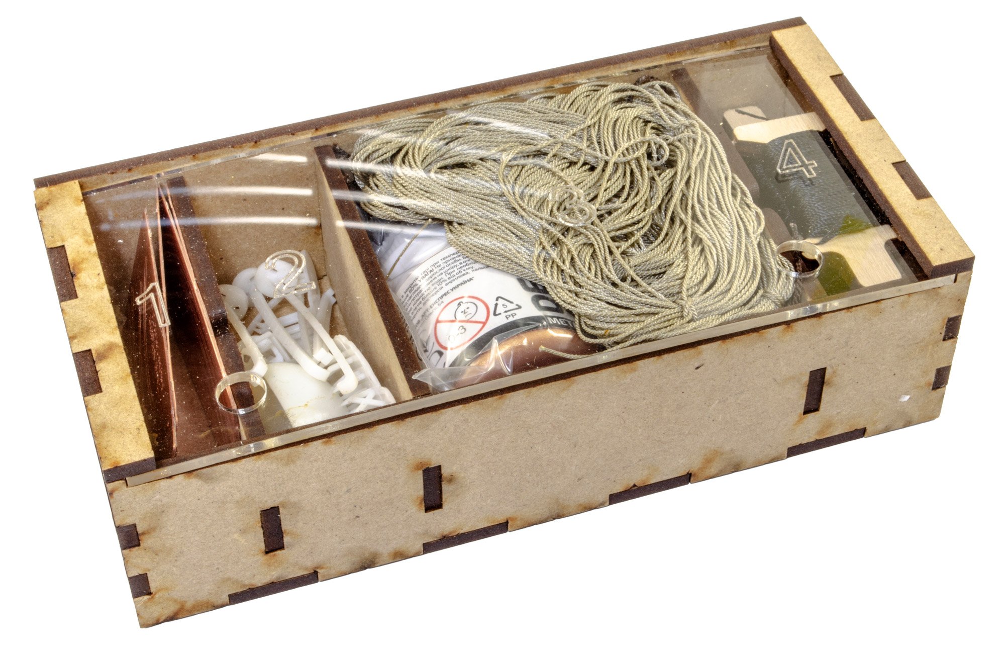
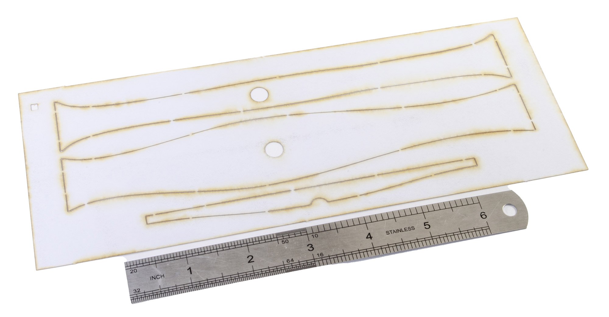
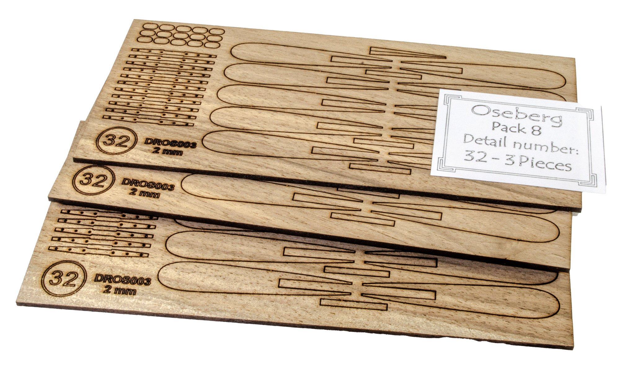
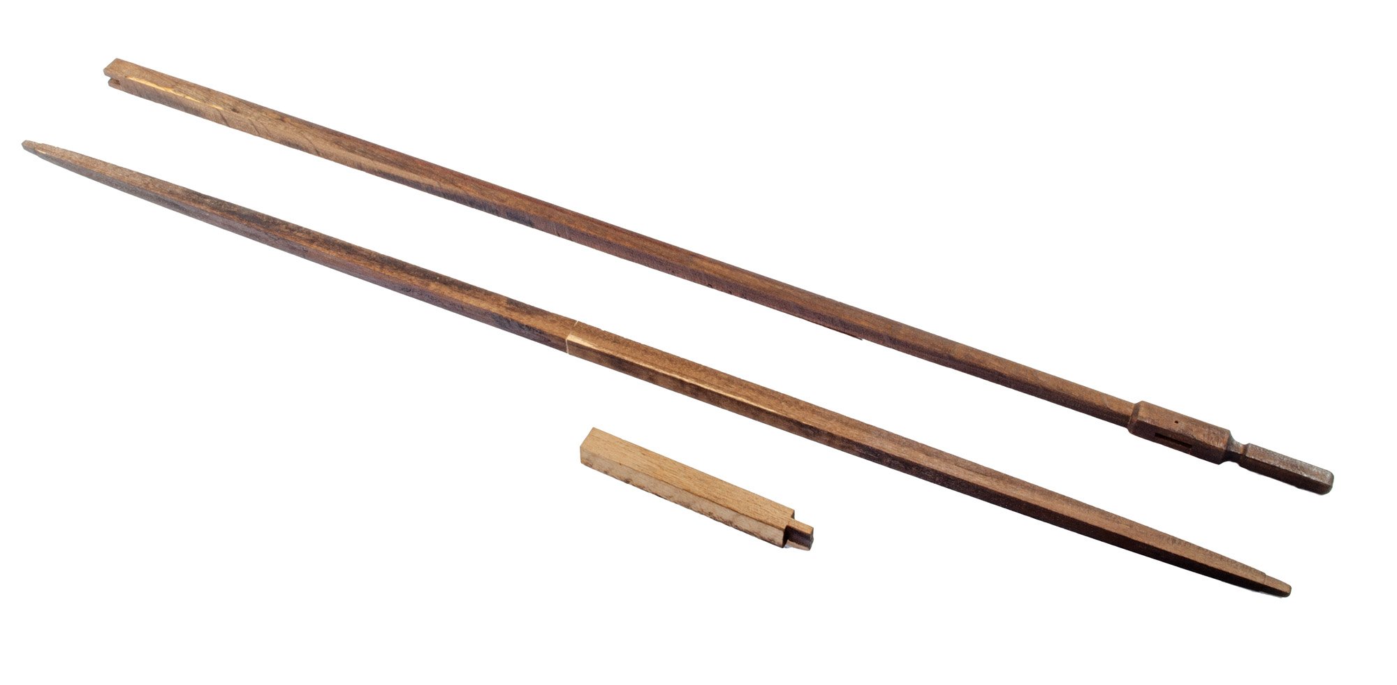
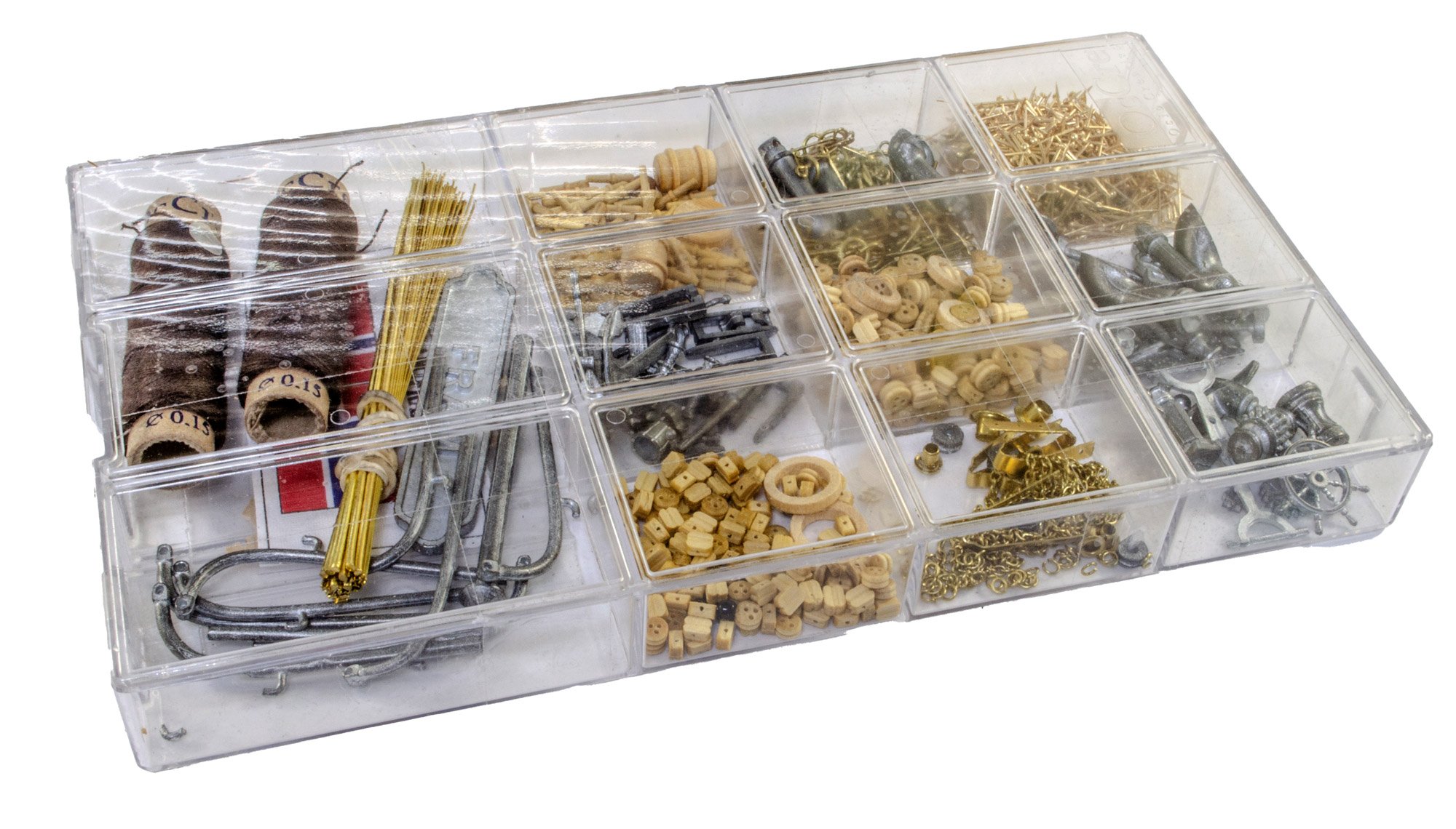
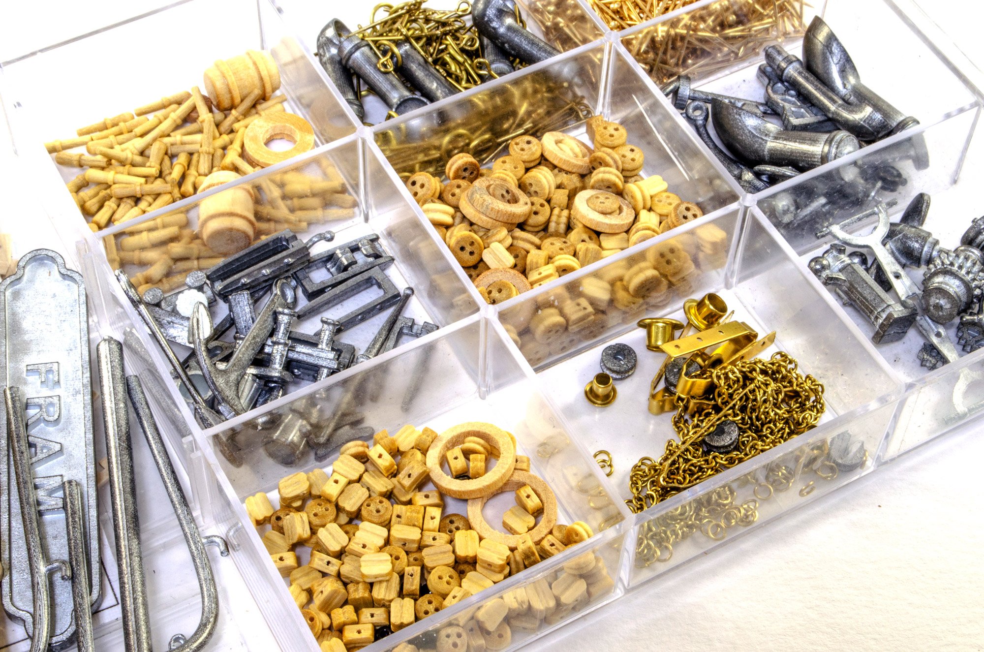
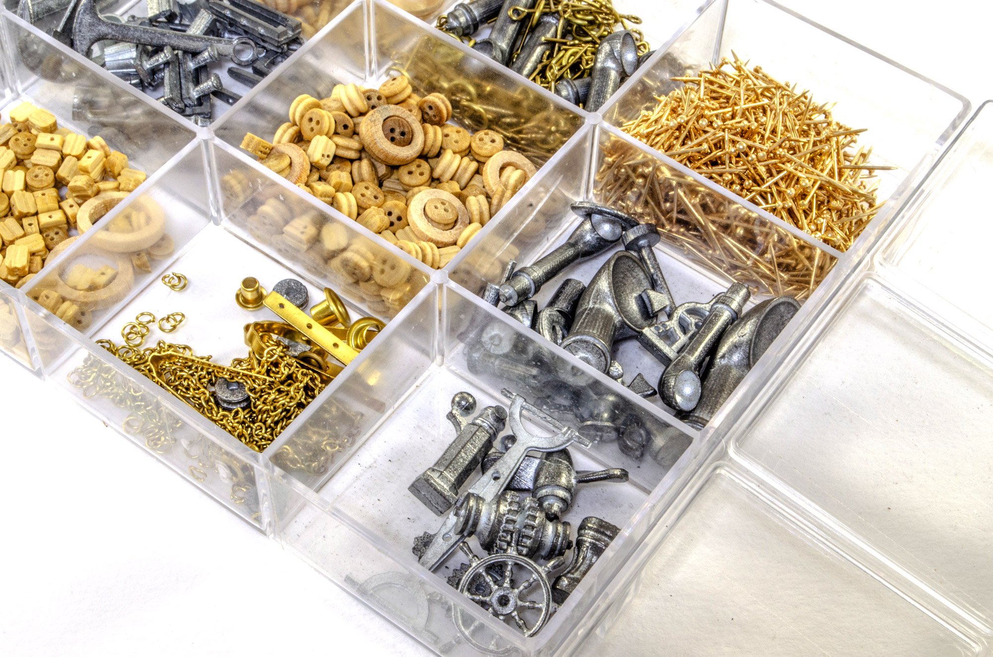
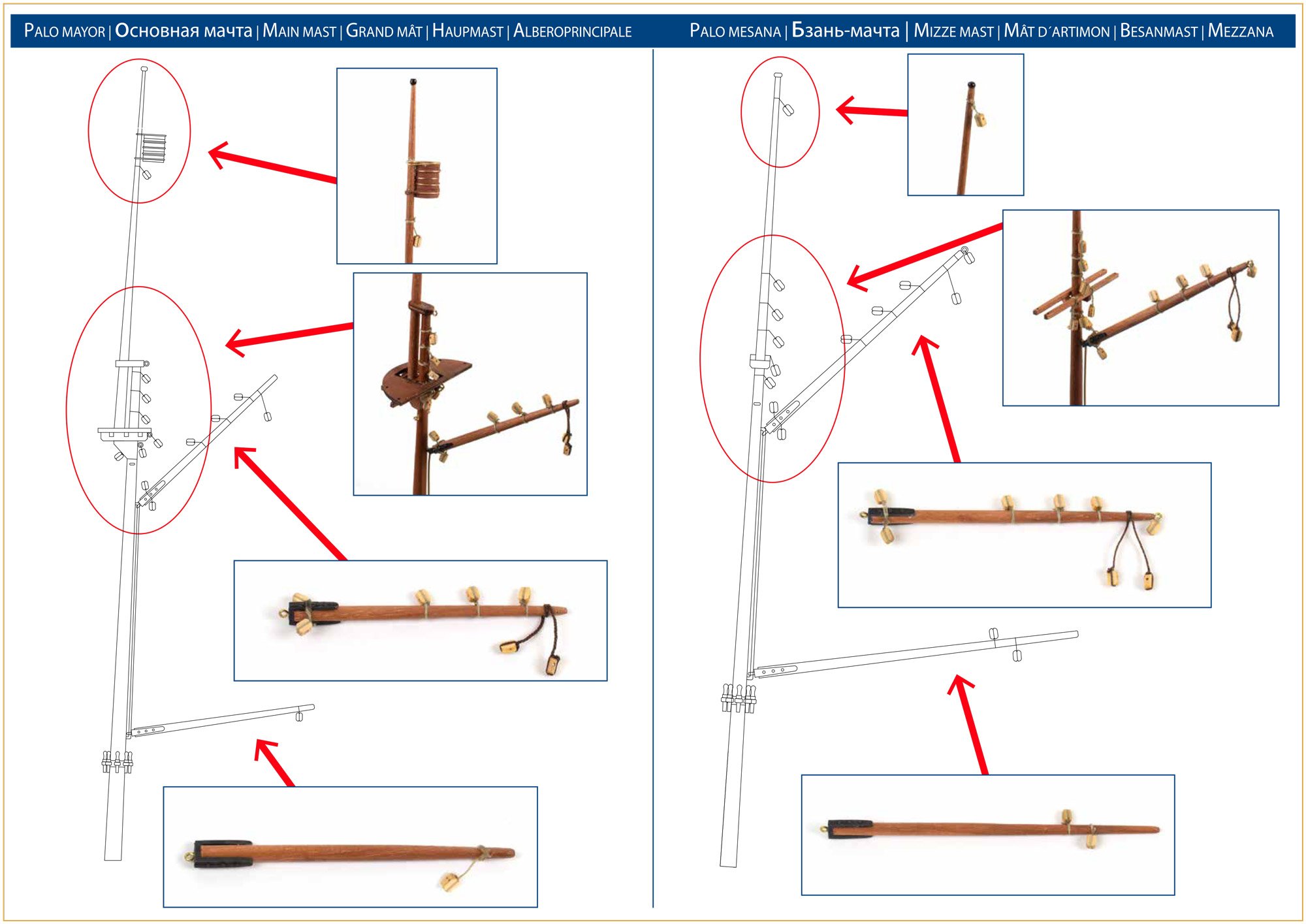
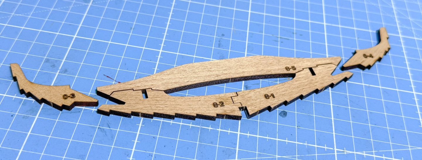
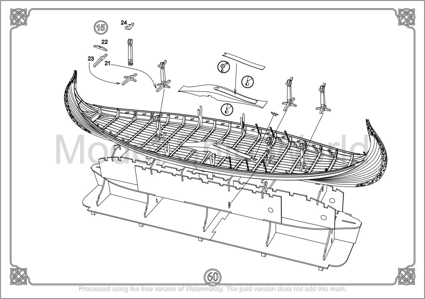
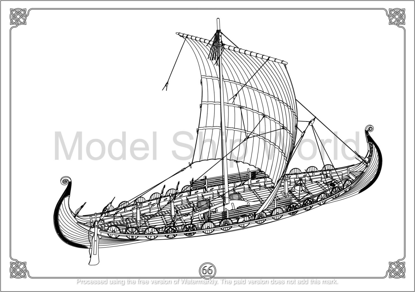
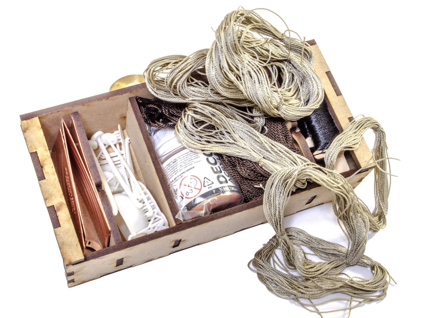
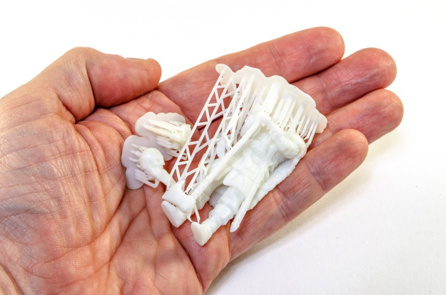
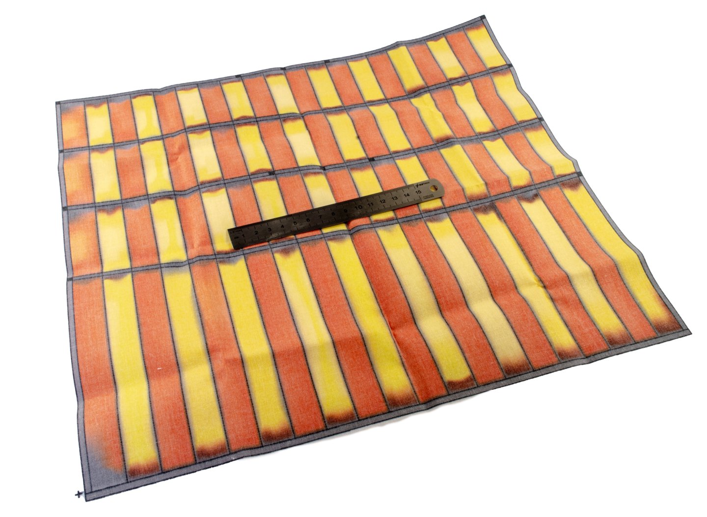
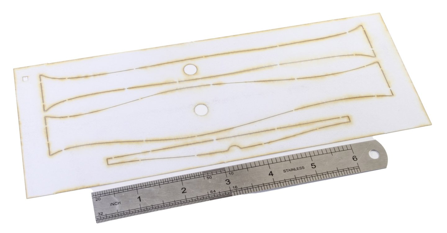
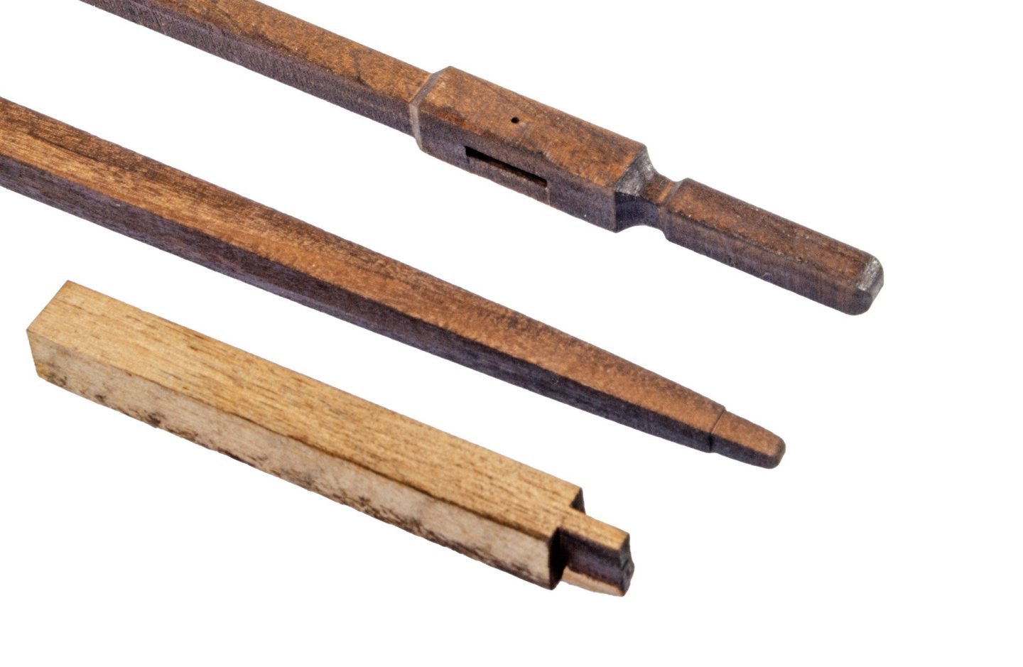
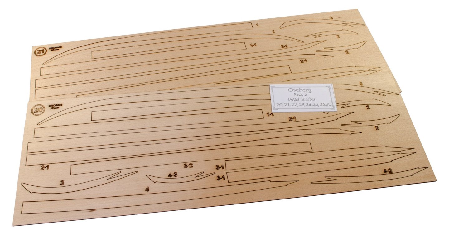
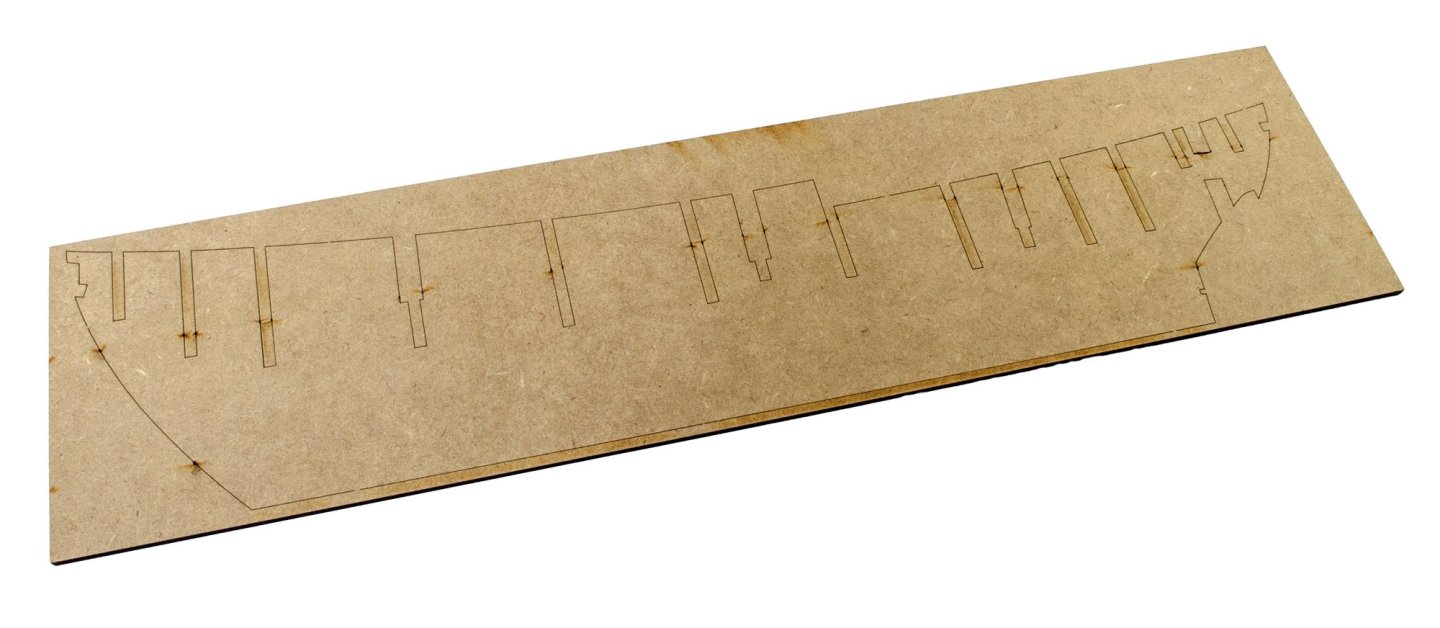
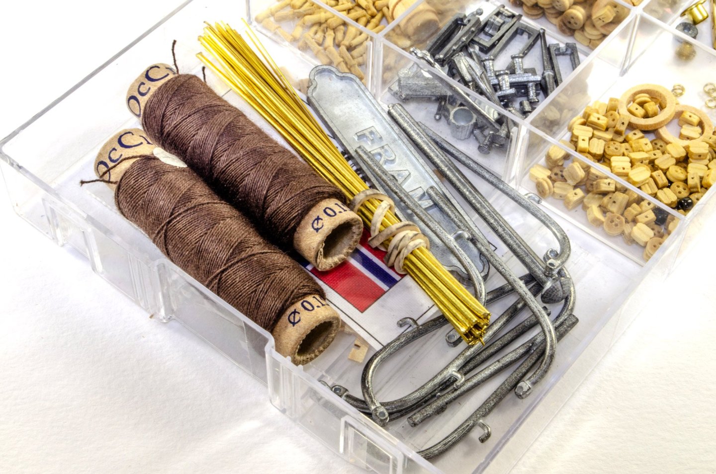
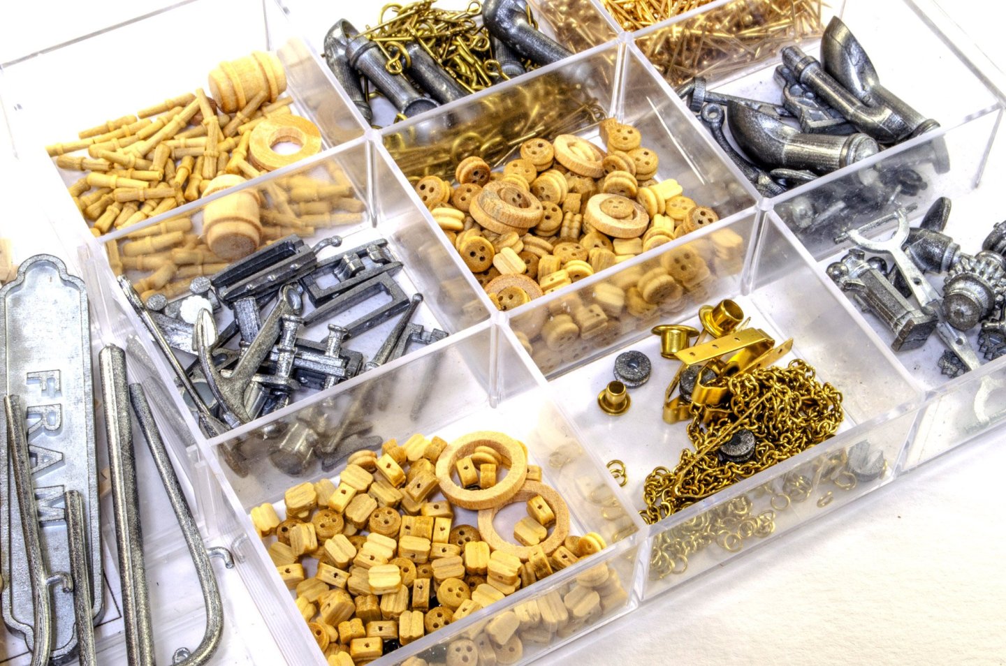
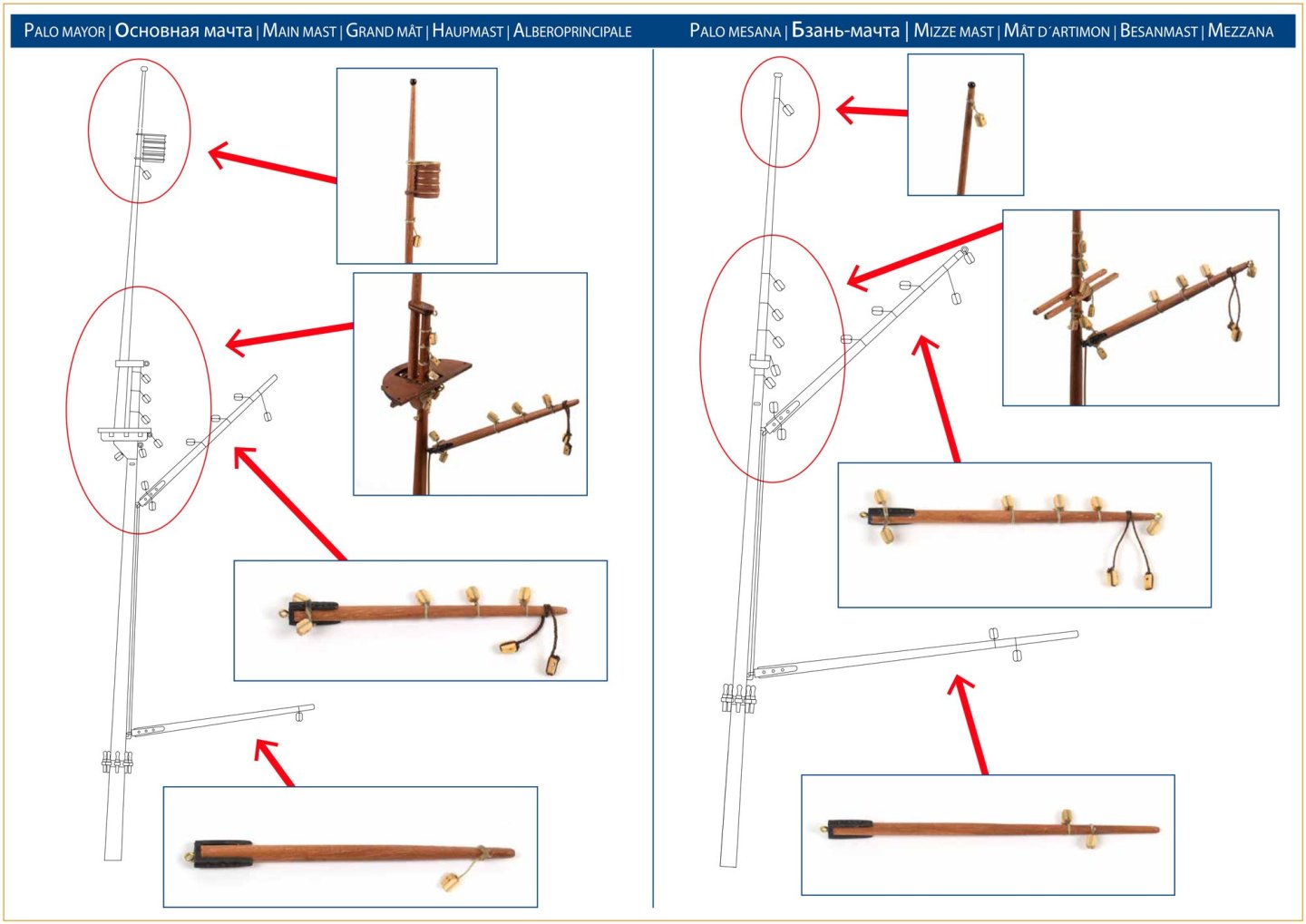
Fittings etc. Two fittings boxes are included in this kit, made from MDF and with a clear acrylic lid which is engraved with the part numbers. In this first box, you can see the 3d-printed shield bosses, as well as the period-correct rigging blocks and cleats etc. The second fittings box contains spools of fuzz-free rigging cord of various colours and diameters, as well as copper parts for the barrels, a 3d-printed galley, copper paint, etc. One stern looking crew member is included as a 3d-print. This will need some assembly and the print frames removing. I may do that soon to get an idea about how he looks, and to pose with the vessel as she's built. Here's a perfect illustration as to the size of the Oseberg....the pre-coloured sail. That's a 6 inch rule for comparison. Yes, she's big! This set of paper templates is for use on the mast fish so it can be shaped to the correct profile from all angles. More soon....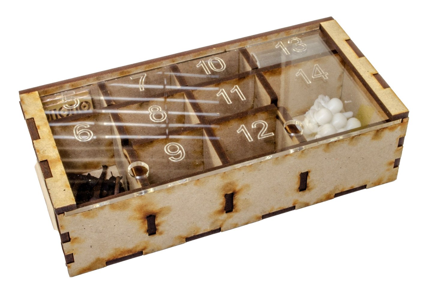


- 14 replies
-
- 14
-
-
-
- Pavel Nikitin
- viking
- (and 2 more)
-
Kit review 1:25 Drakkar ‘Oseberg’ V3 - Ships of Pavel Nikitin
James H replied to James H's topic in REVIEWS: Model kits
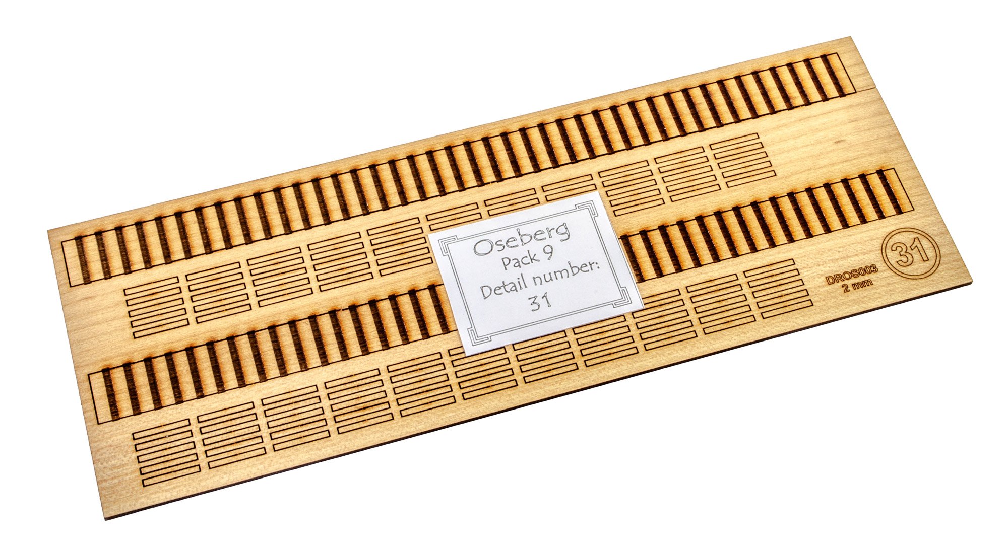
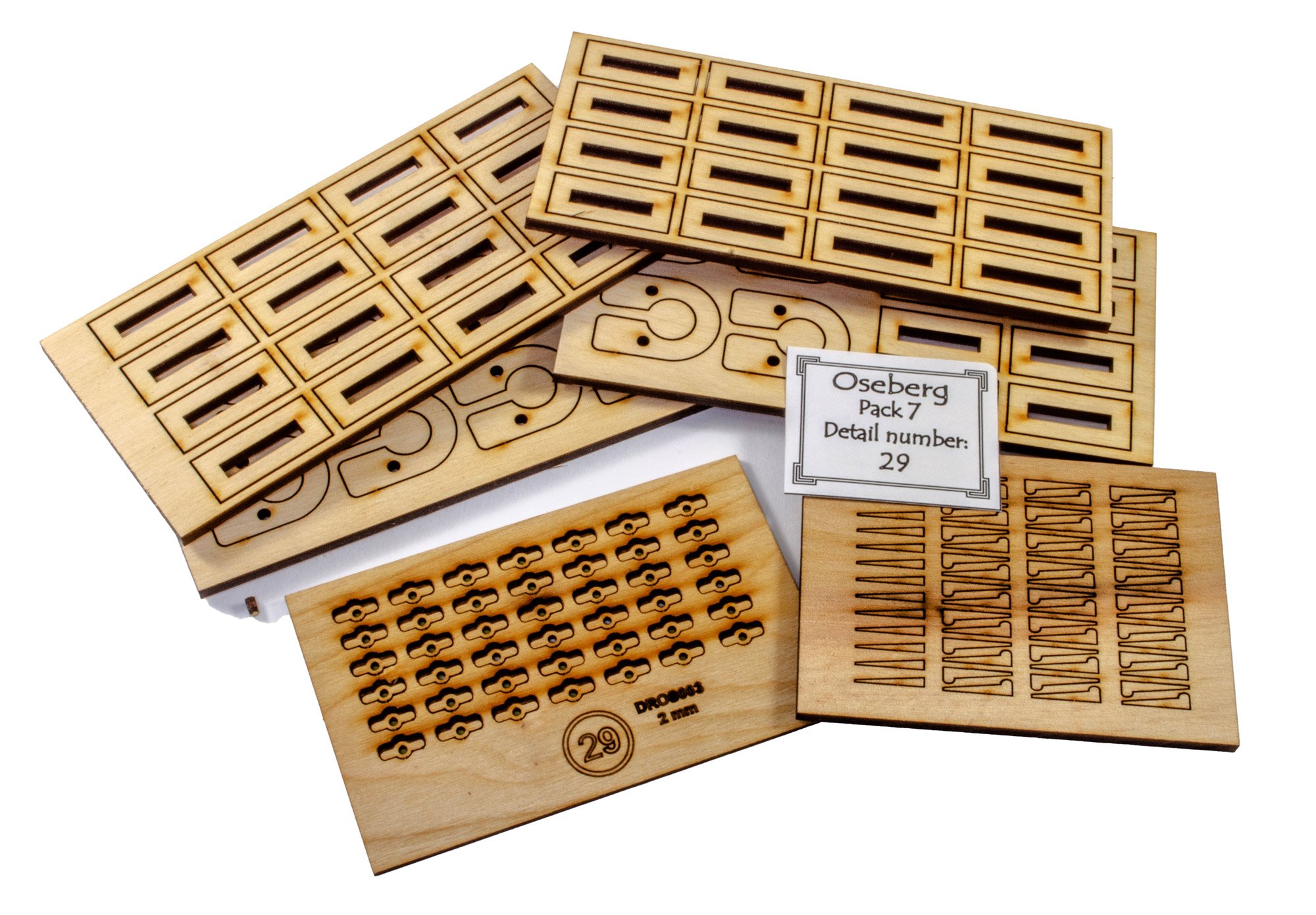
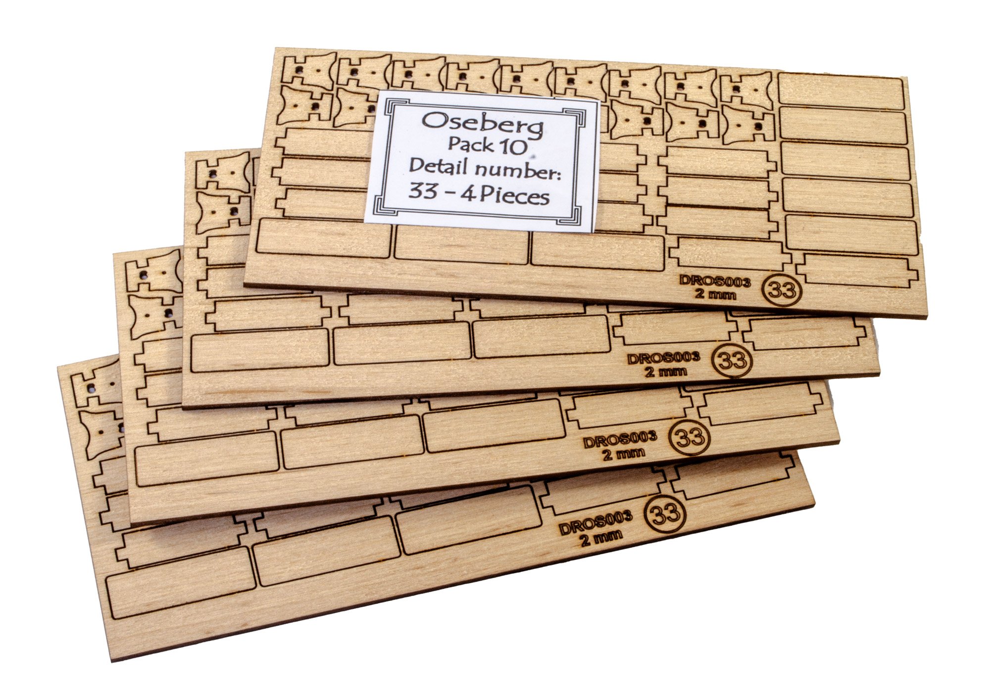
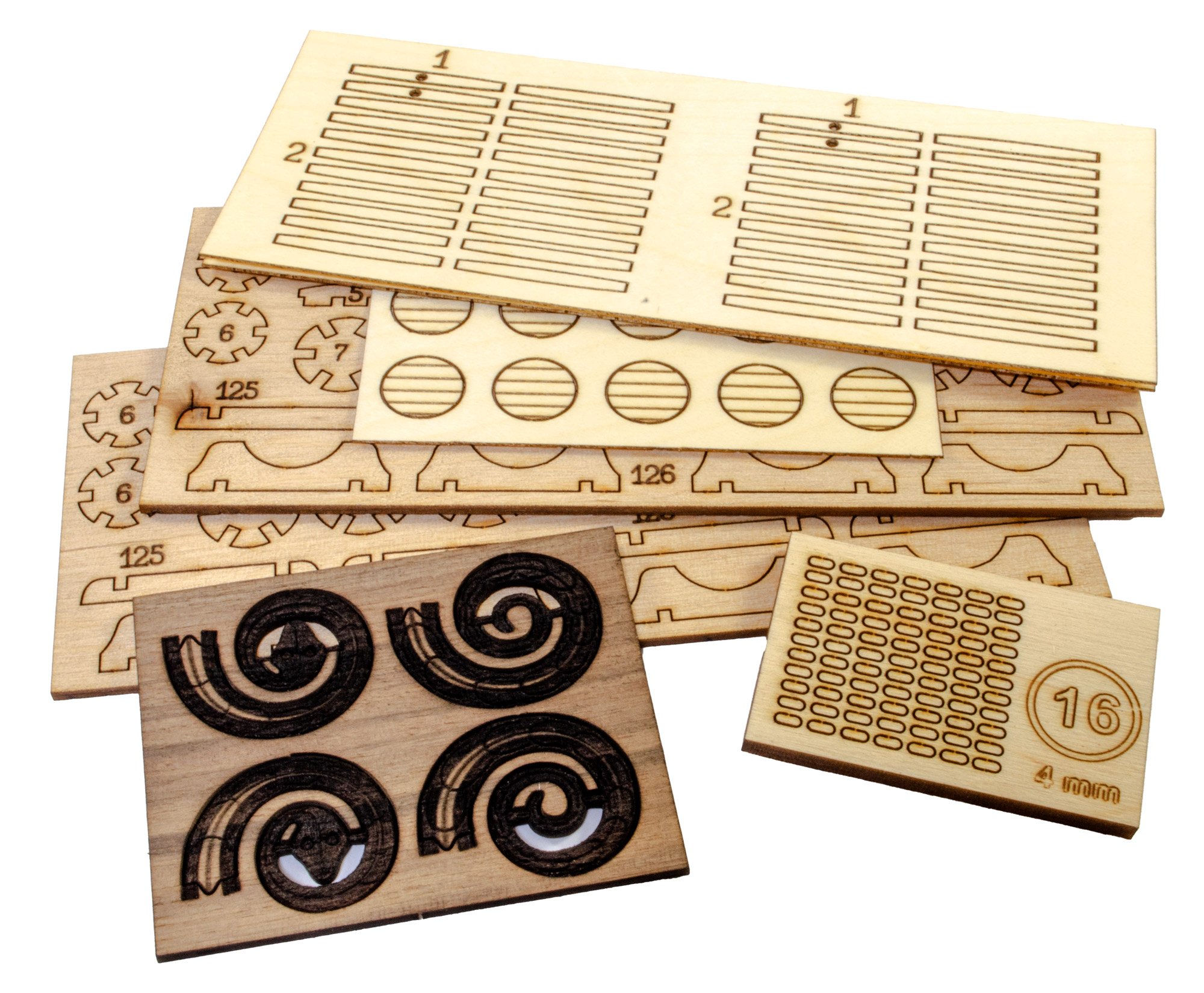
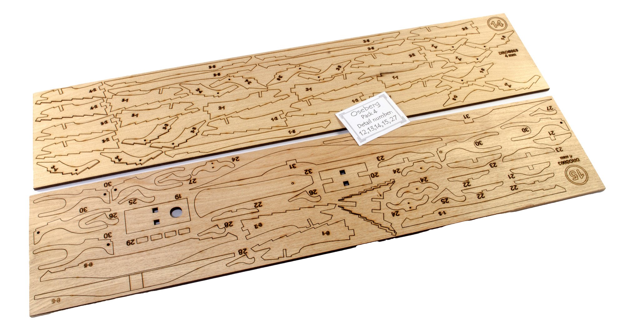
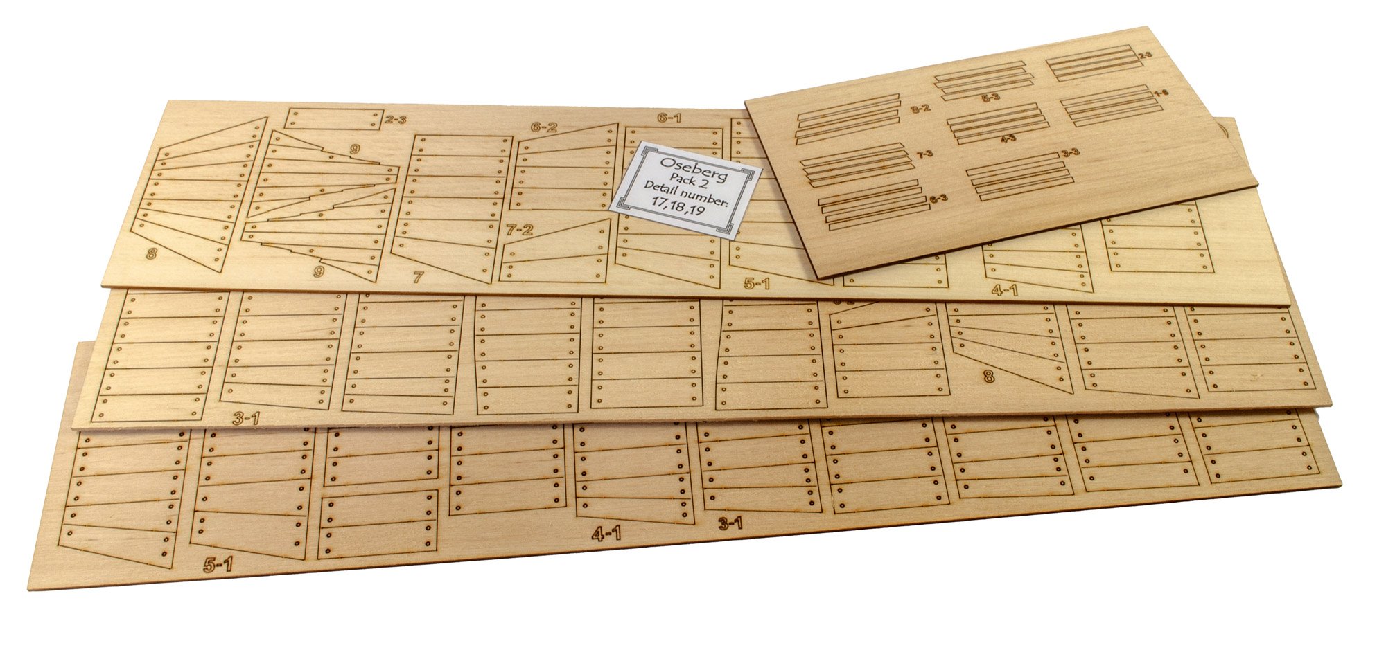
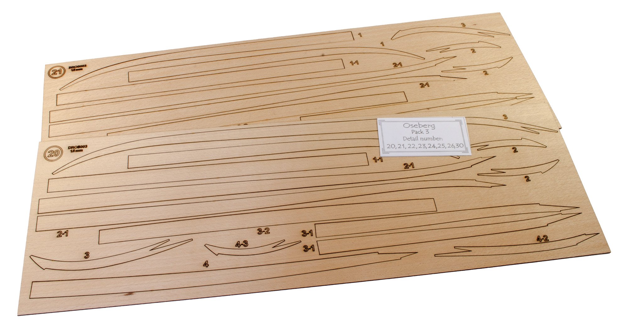
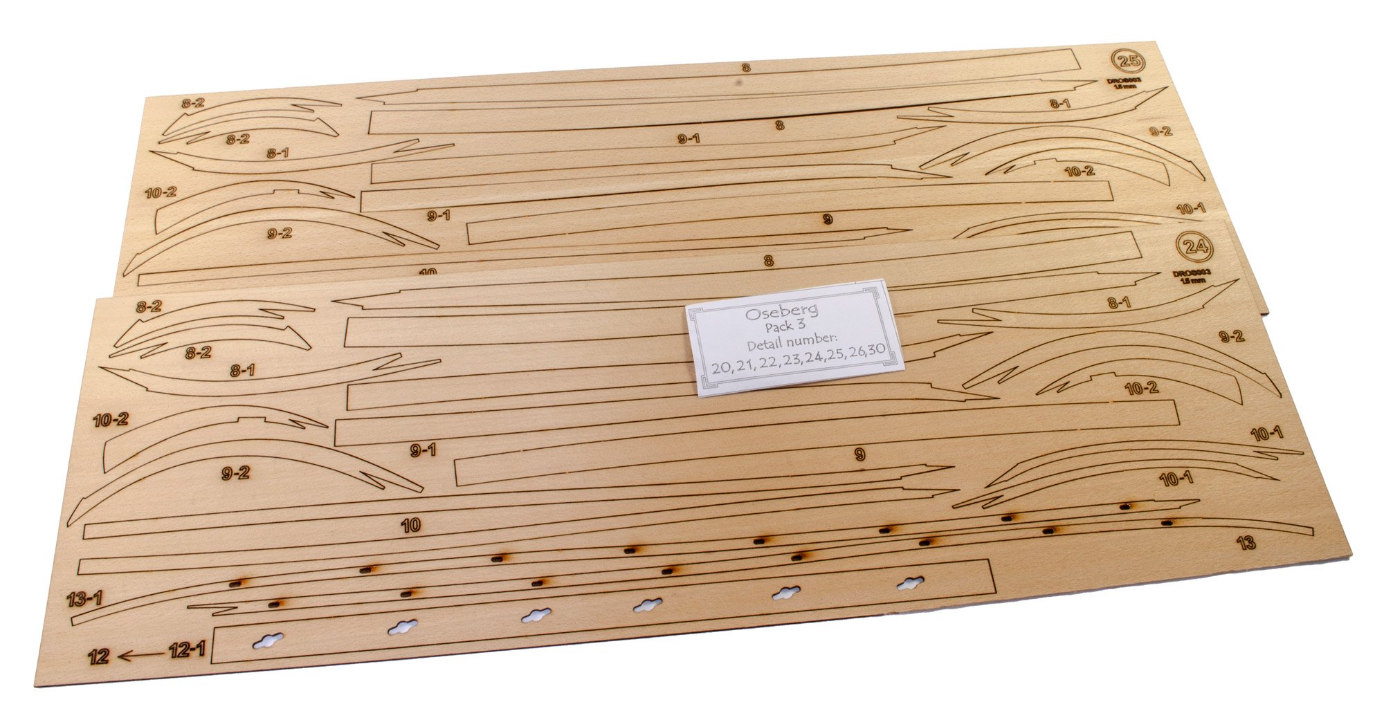
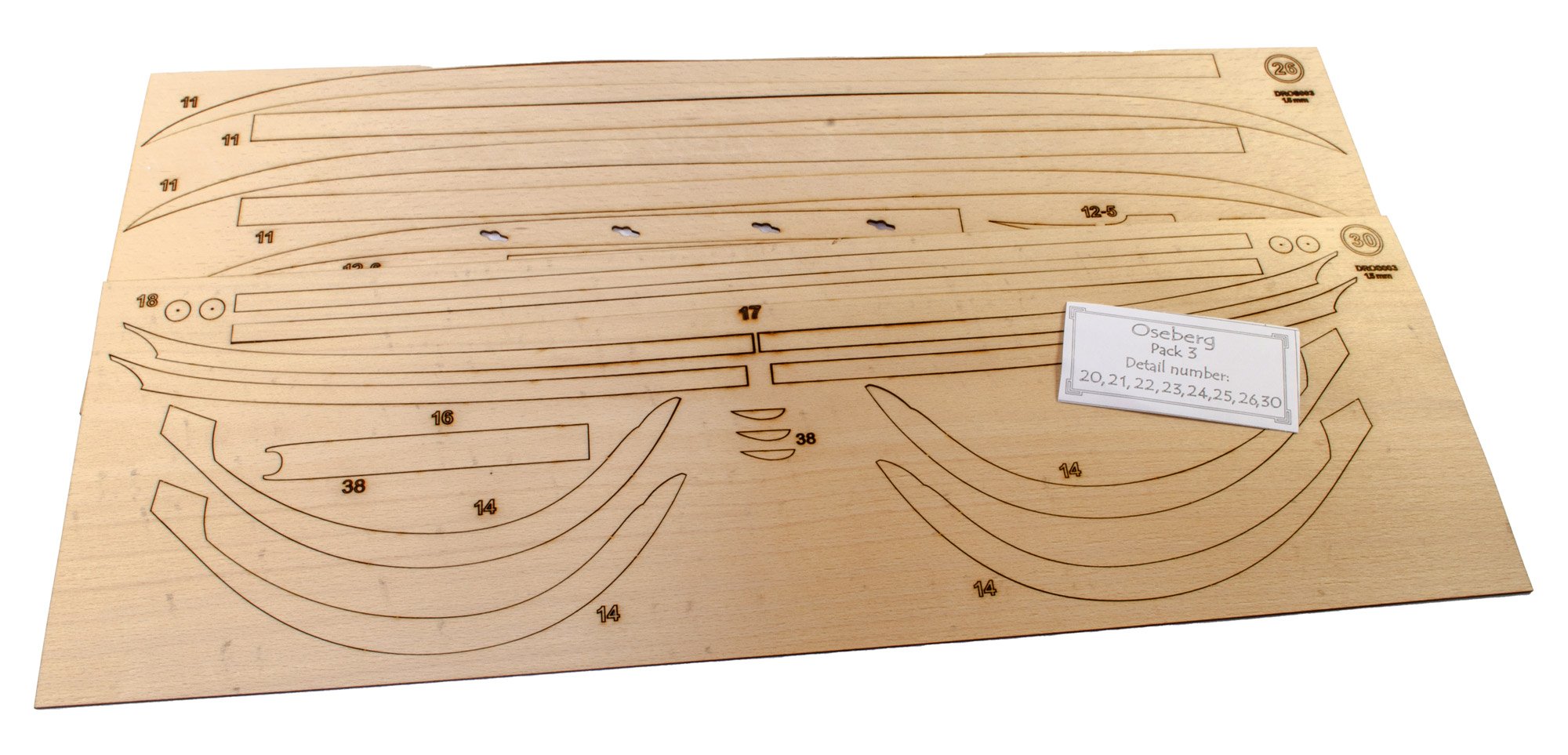
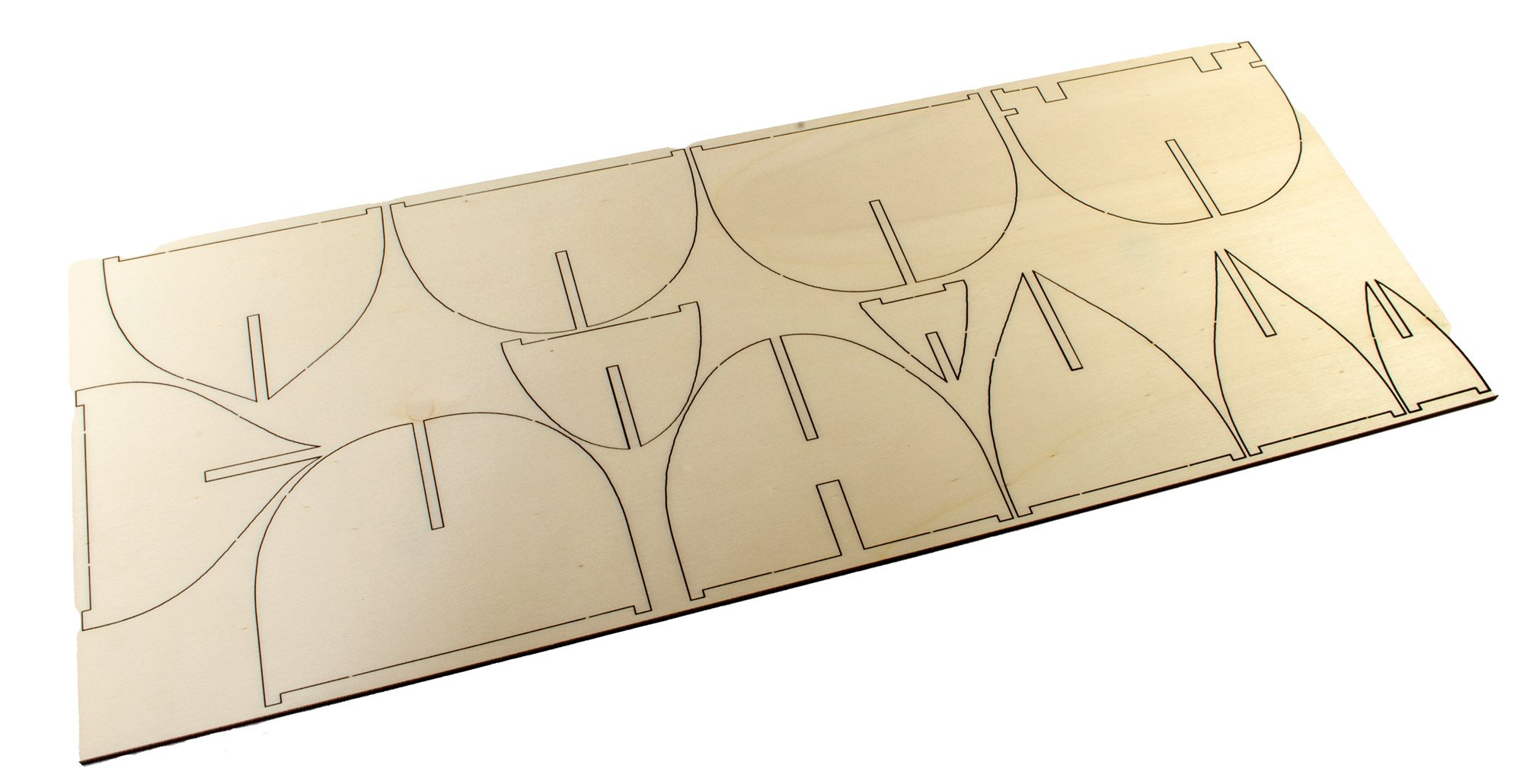
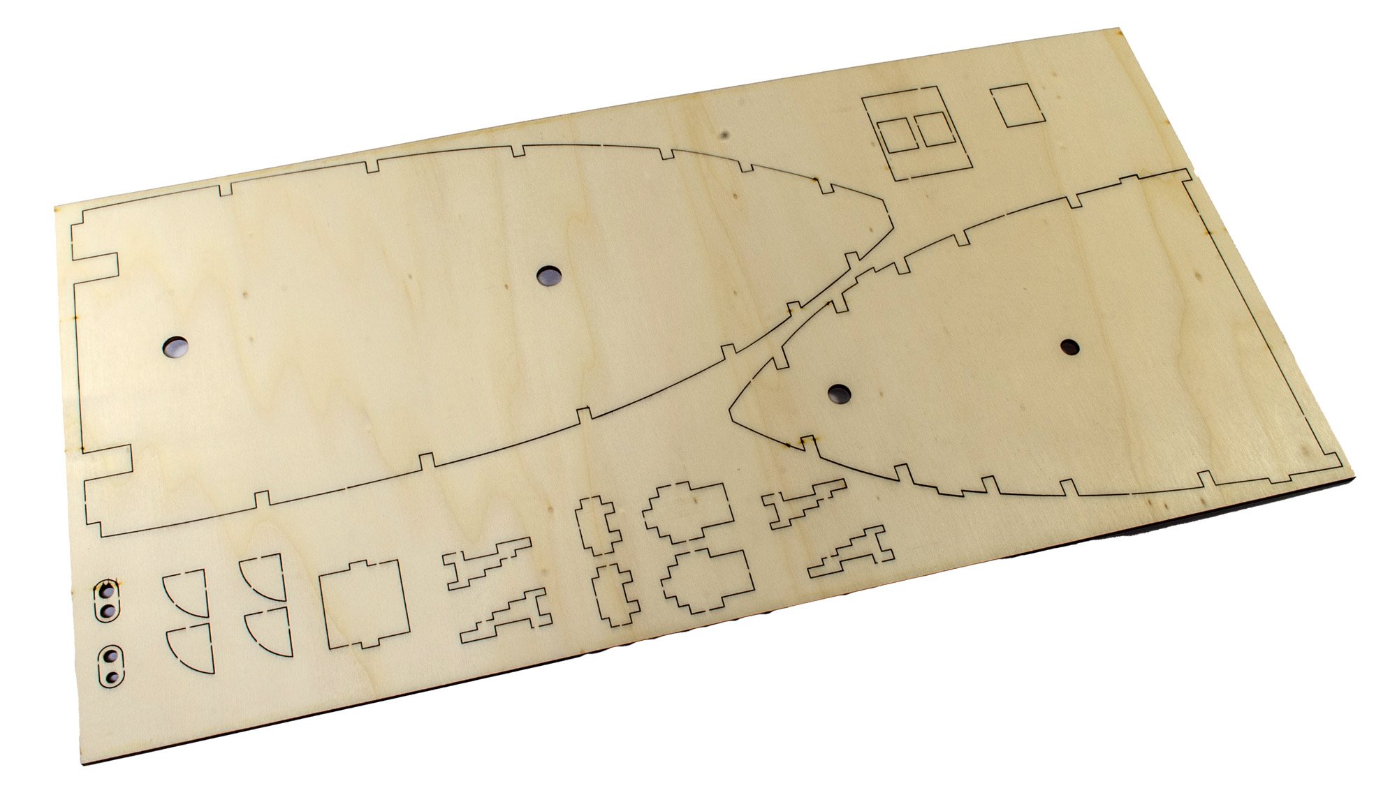
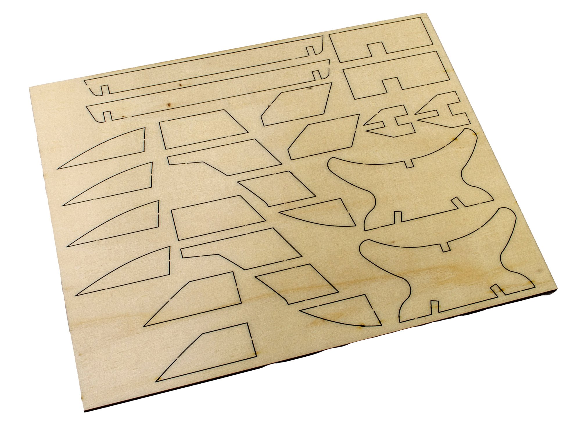
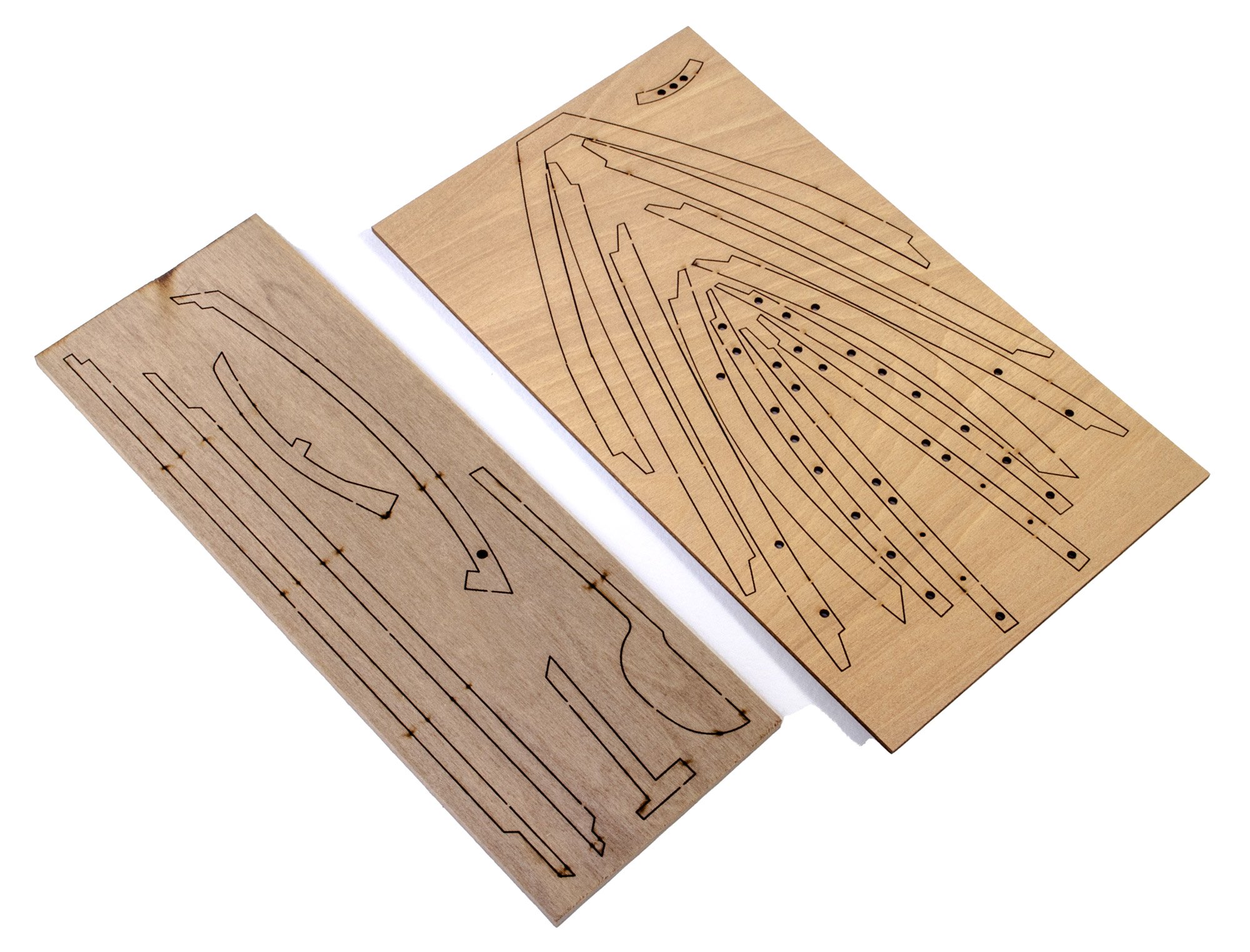
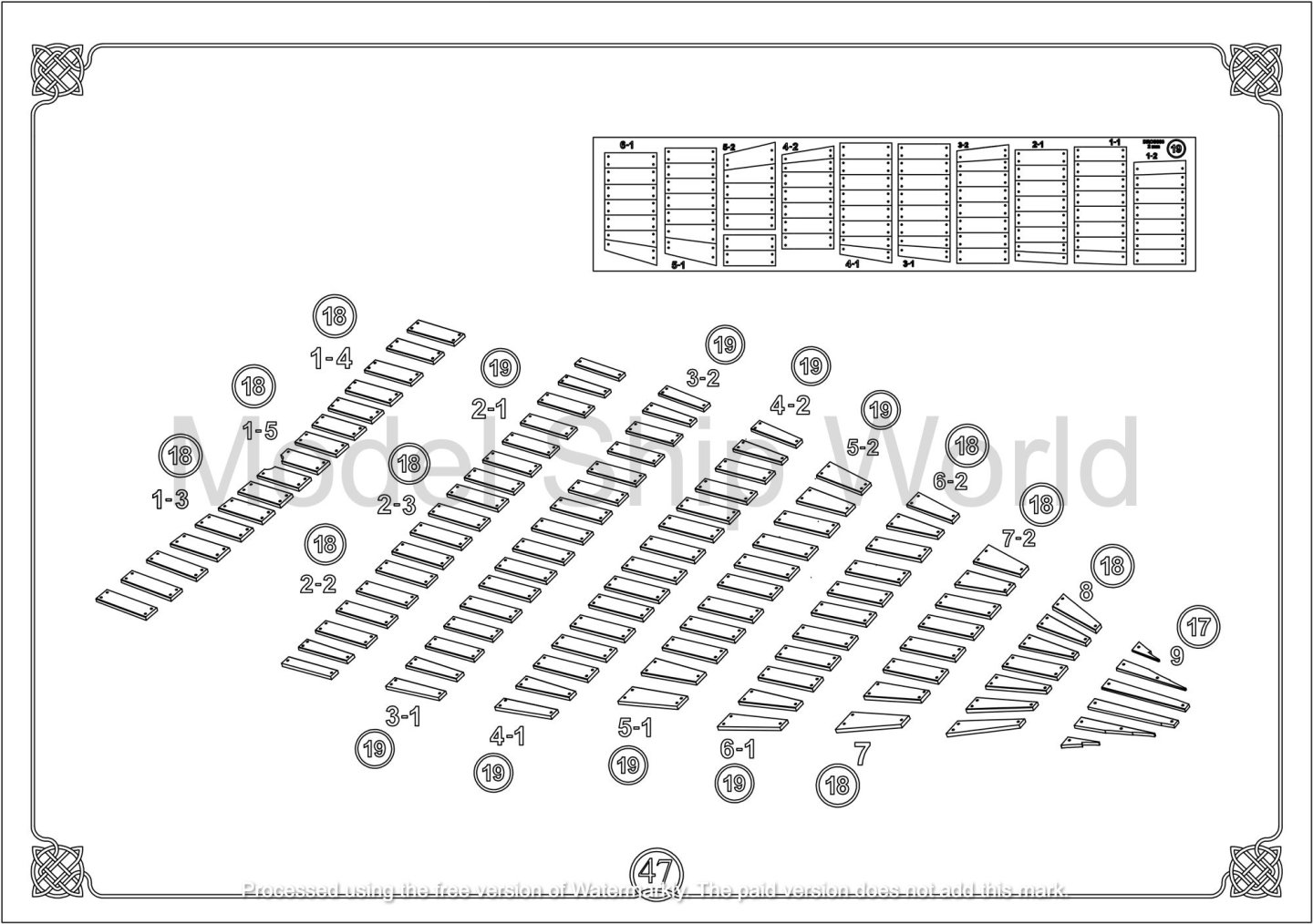
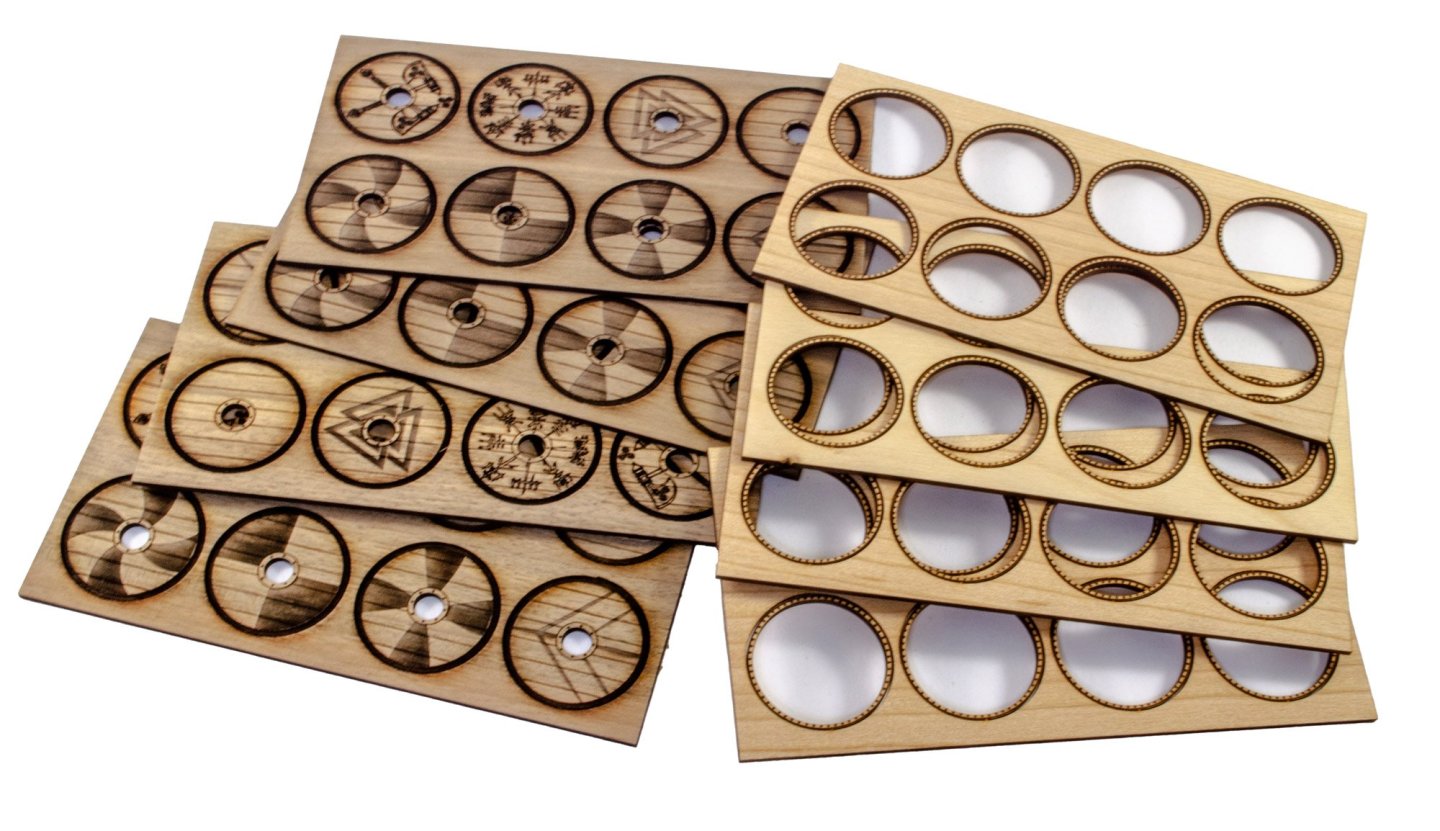
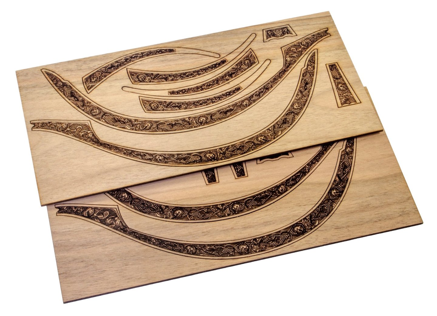
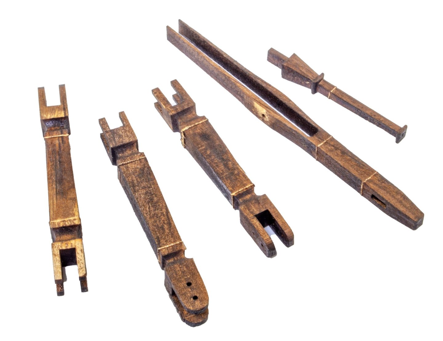
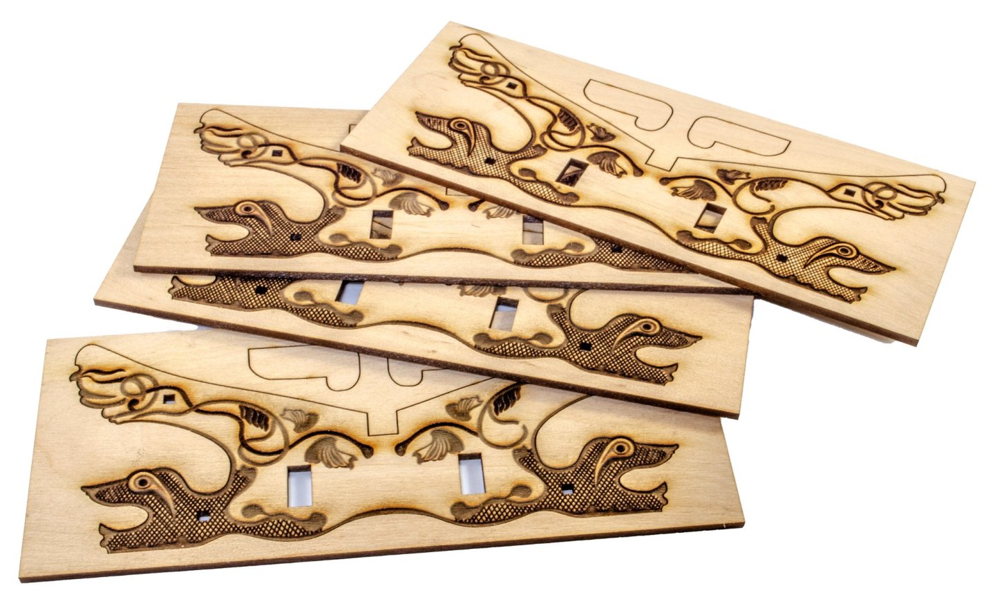
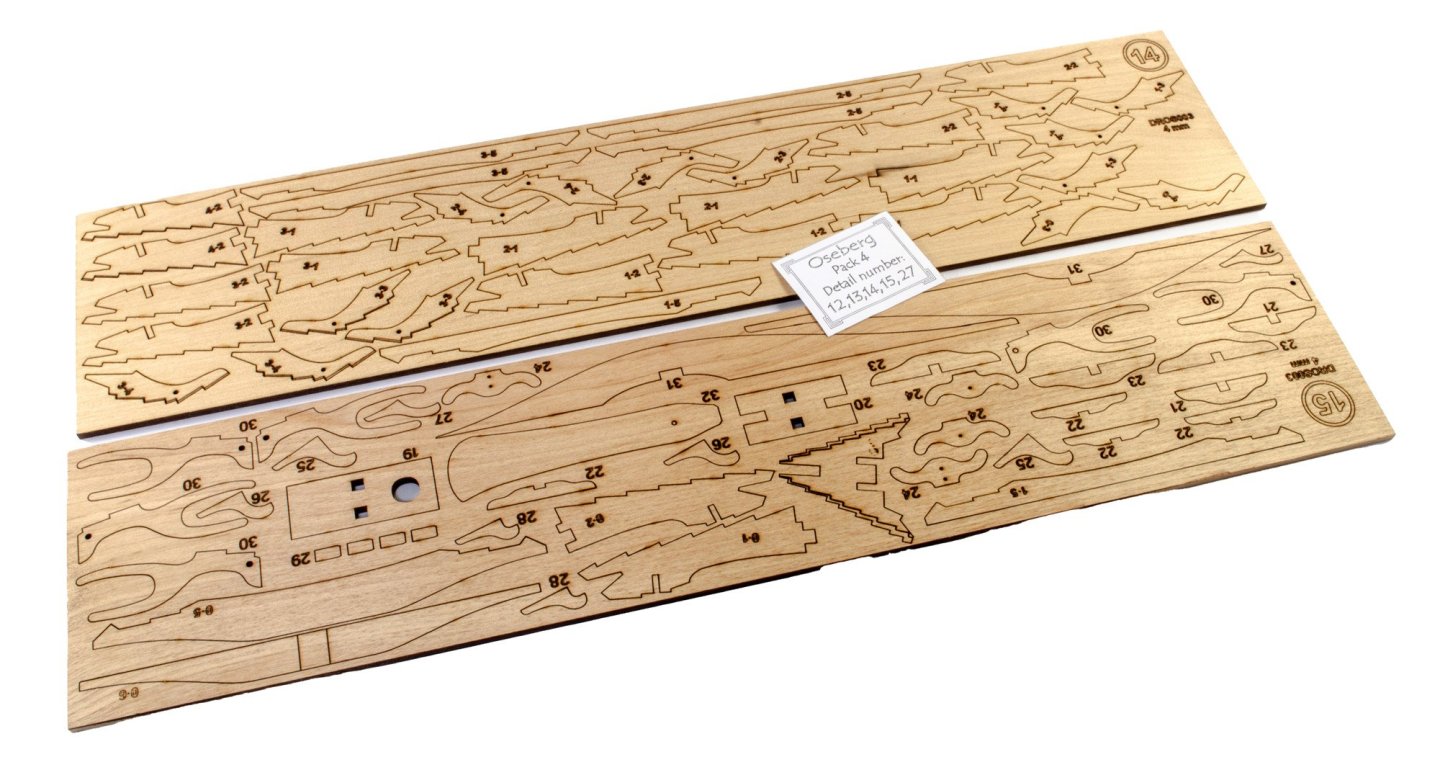
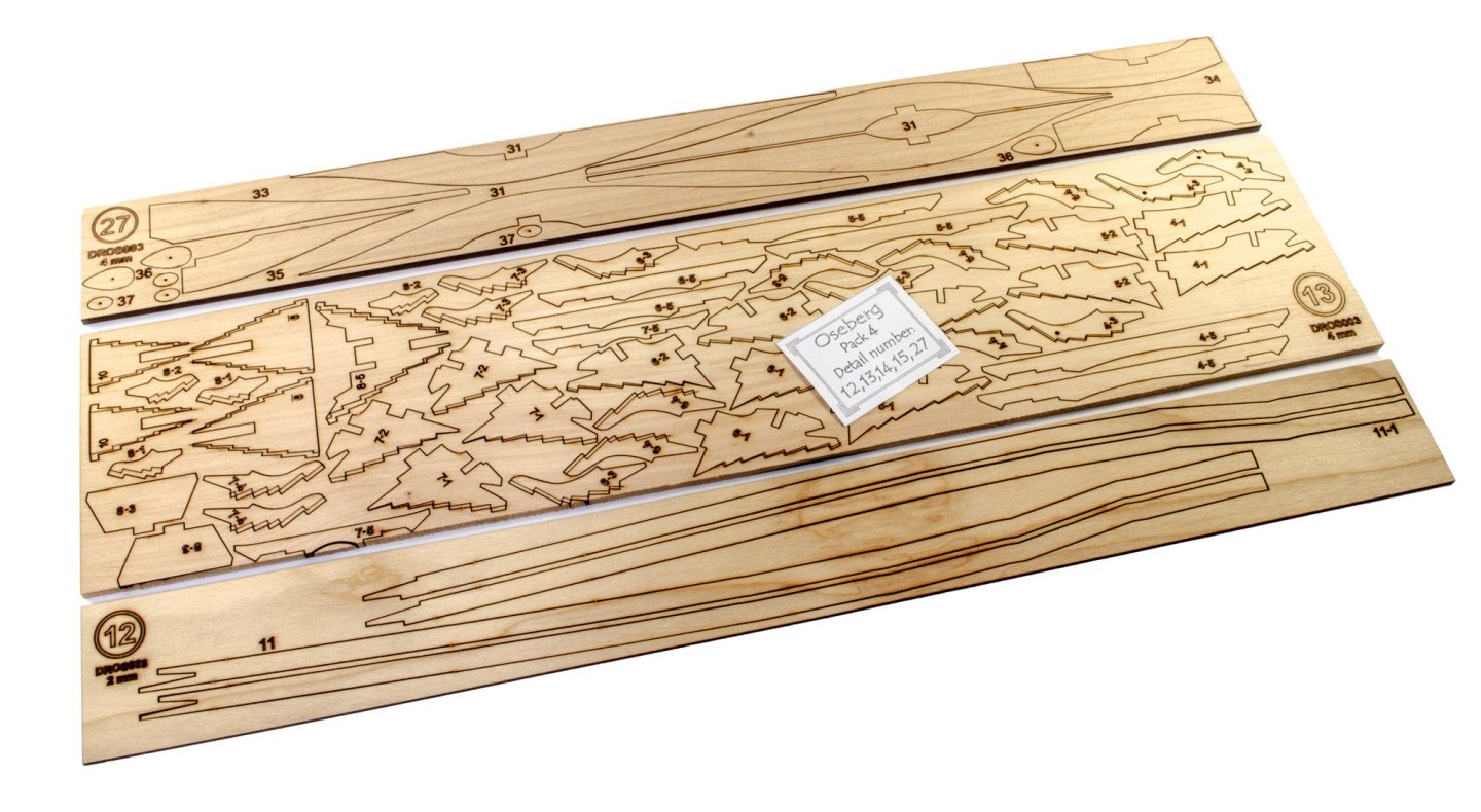
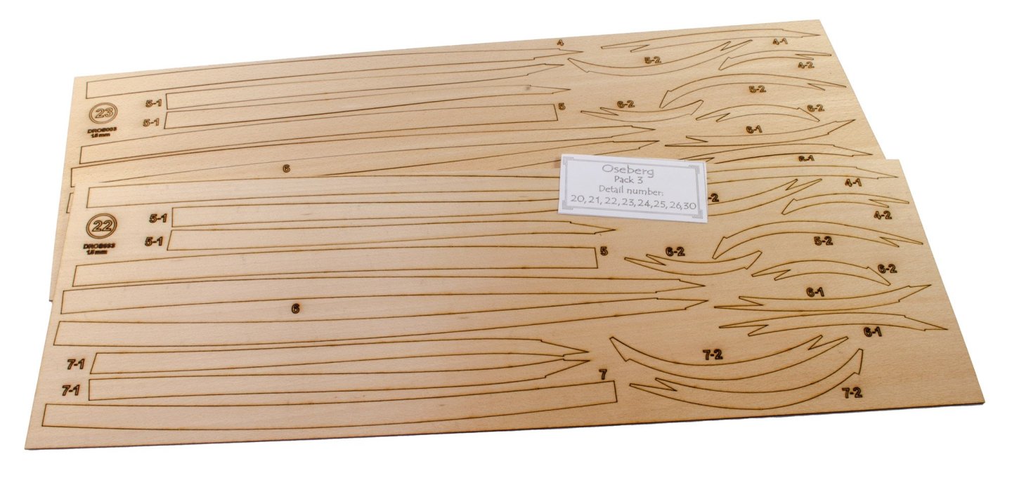
I've not currently had the time to go through the entire box and deduce what the parts all are, but you cab clearly identify a number of parts, such as the tread boards which fit on deck, and the multipart shields. The latter have their forward rims cut as separate parts, and the shield itself is recessed along the circumference, so these should fit perfectly. The engraving detail in the shields is excellent. The hollow centres will be fitted with 3D-printed bosses. These are the benches on which the crew sit. I believe they may also have doubles as chests for belongings. Here you can see the ornate 'carvings' which adorned both the bow and stern of the Oseberg. These are just beautiful. The material here is walnut. Barrels are supplied to add to the deck detail, plus their plinths. Copper is supplied for the bands. The engraved parts for the bow and stern (seen bottom left) are a little heavy, but Pavel is sending out a replacement as I type this. These walnut sheets contain the paddles for the oars, as well as handles for the thirty-two shields that will adorn the edge of the hull. This something you don't often seen in a kit....laser shaped parts, including those for the mast and yard etc. The latter will just need rounding off, while others (immediately below) will just need char removal and all the shaping is totally done for you. A pack of dowel is also included, for their handles. I can't see what the long sections of timber are for. Nothing in the manual is shouting out at me. Maybe they are just packing strips, but I'll keep an eye out to see if I can place them. More soon.....


- 14 replies
-
- 11
-
-
-
- Pavel Nikitin
- viking
- (and 2 more)
-
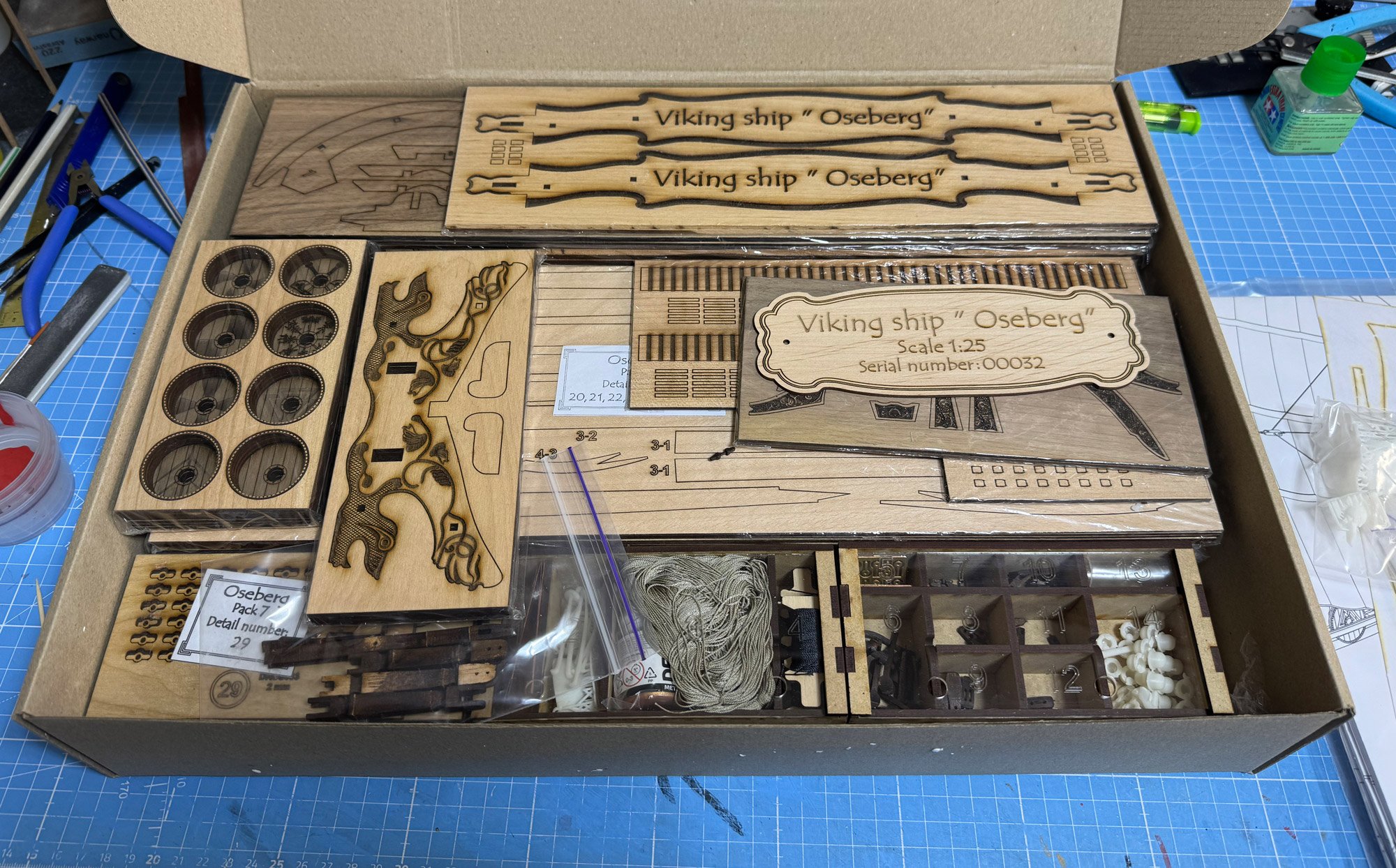
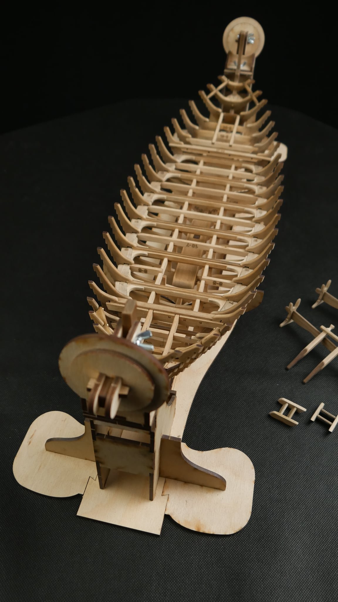
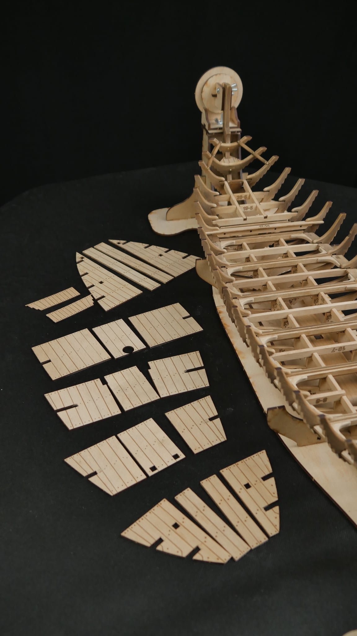
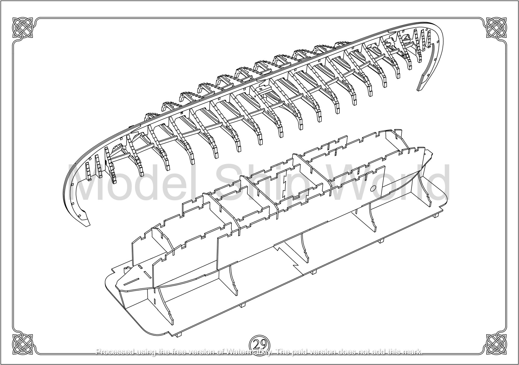
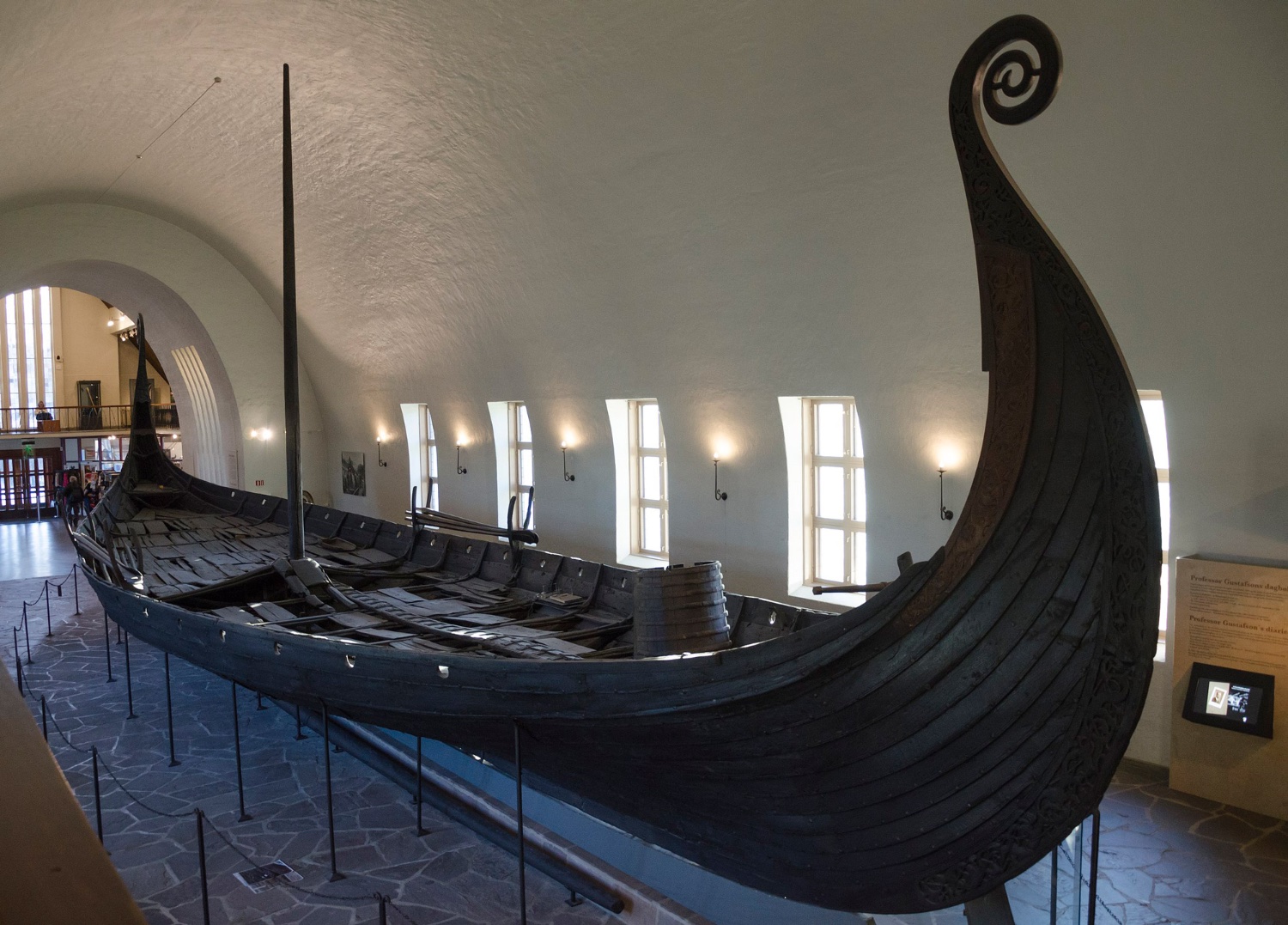
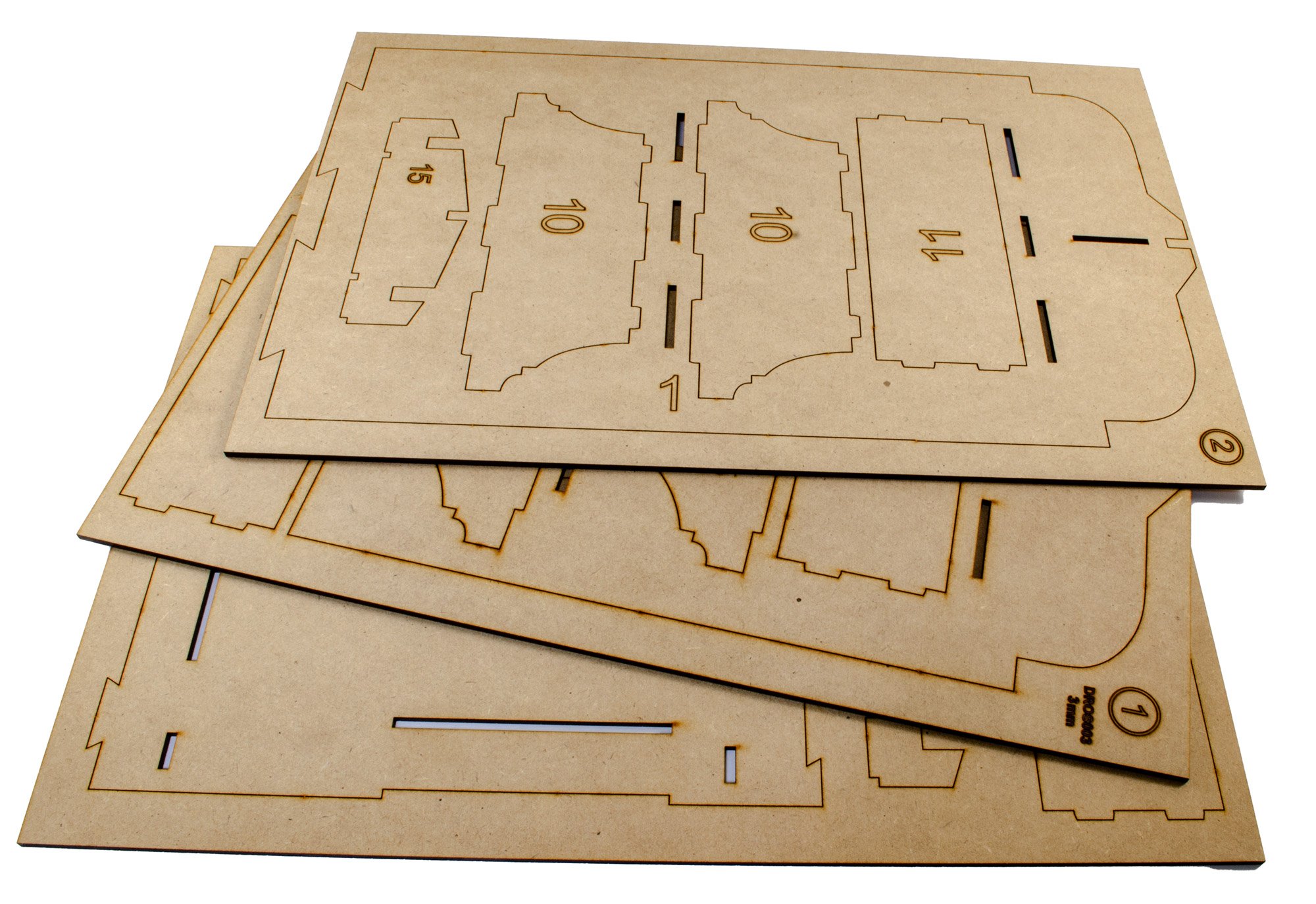
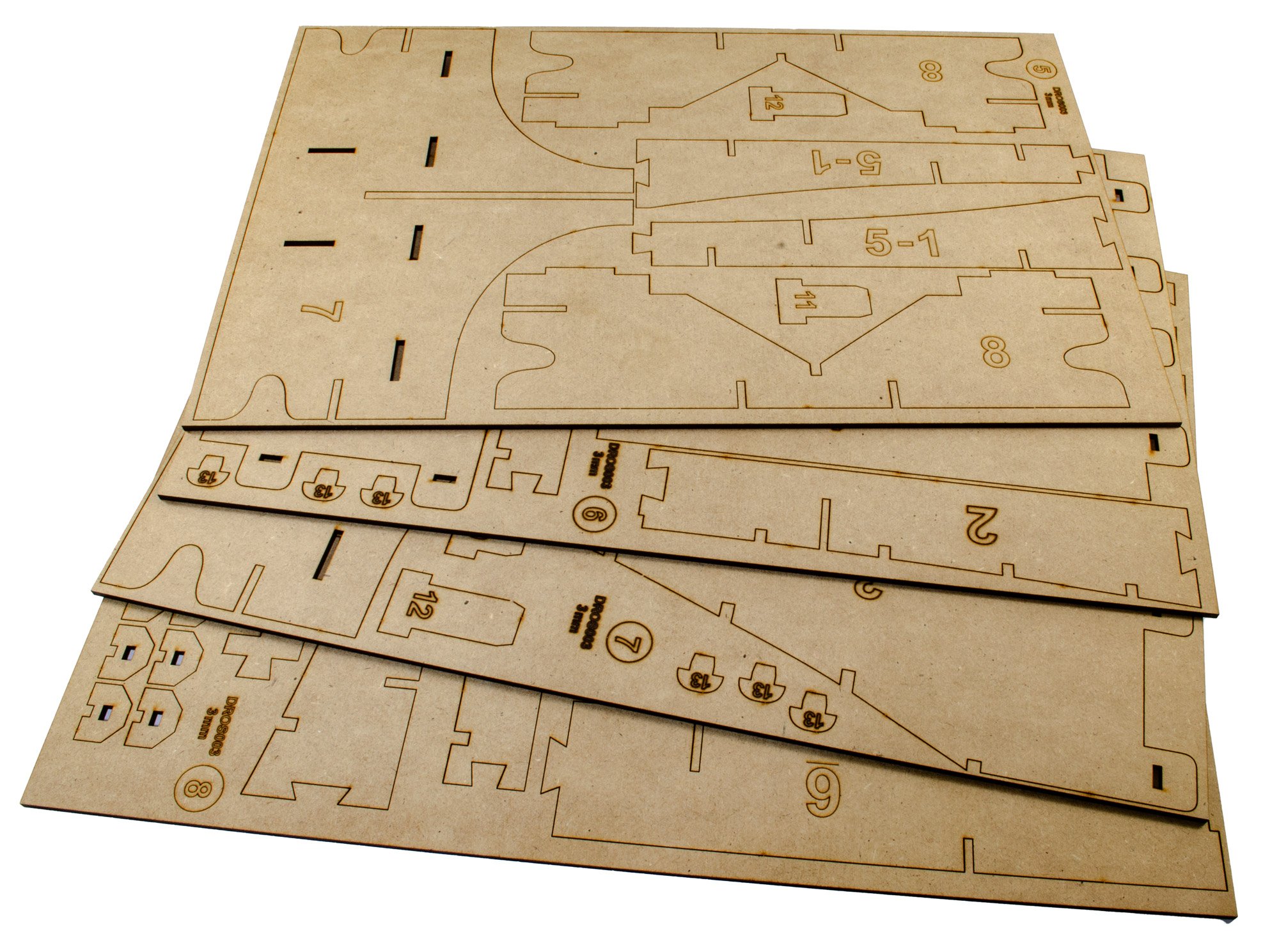
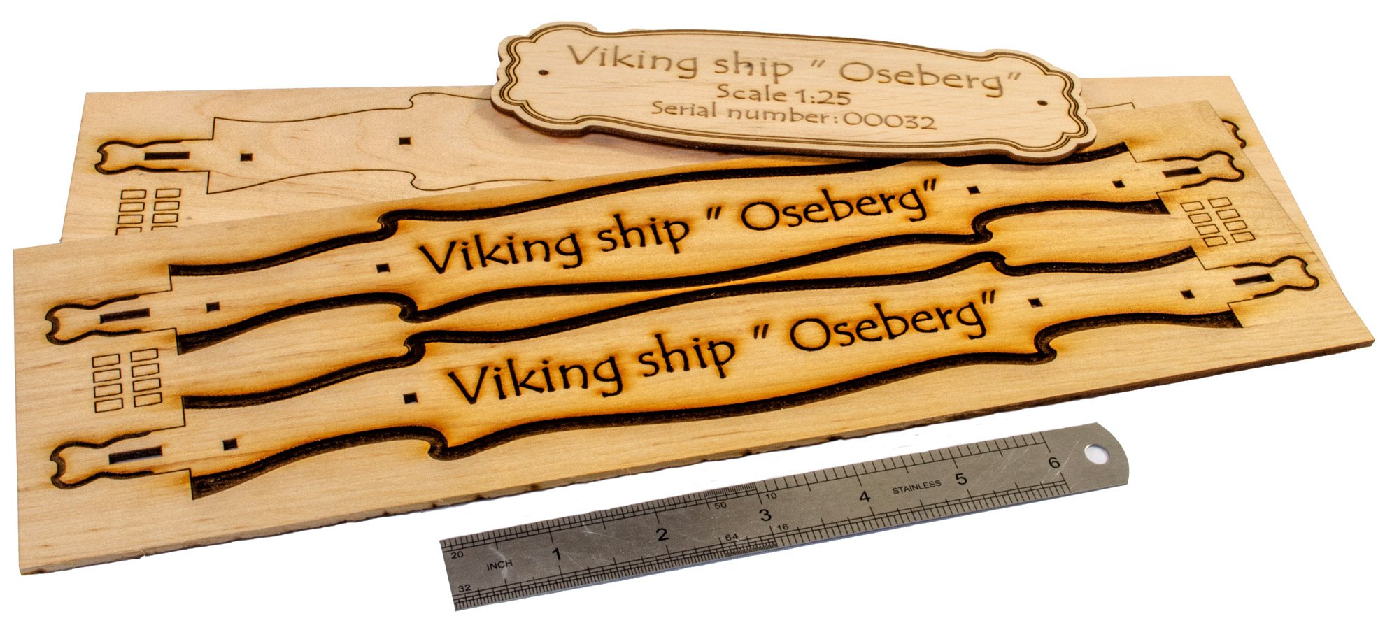
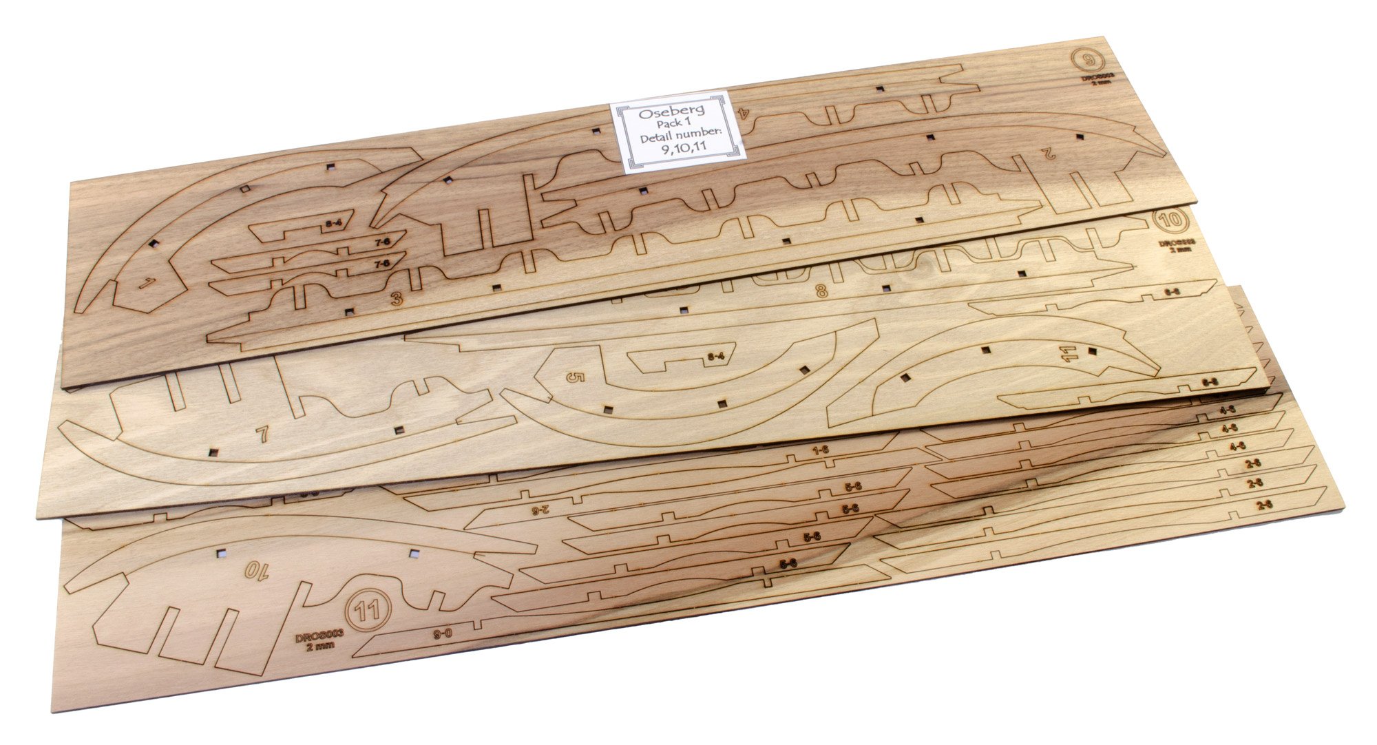
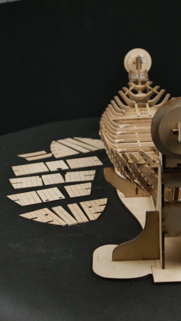
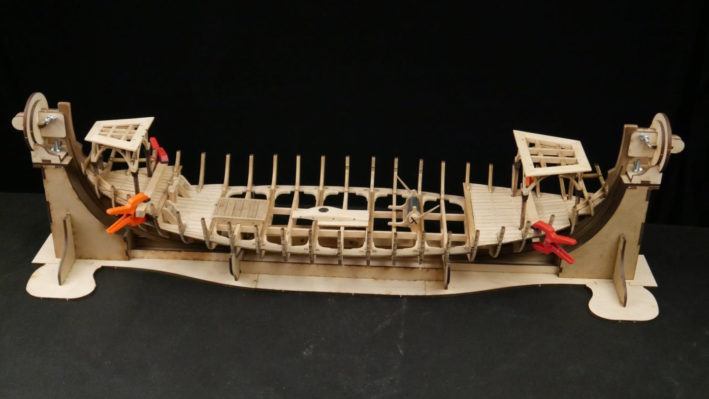
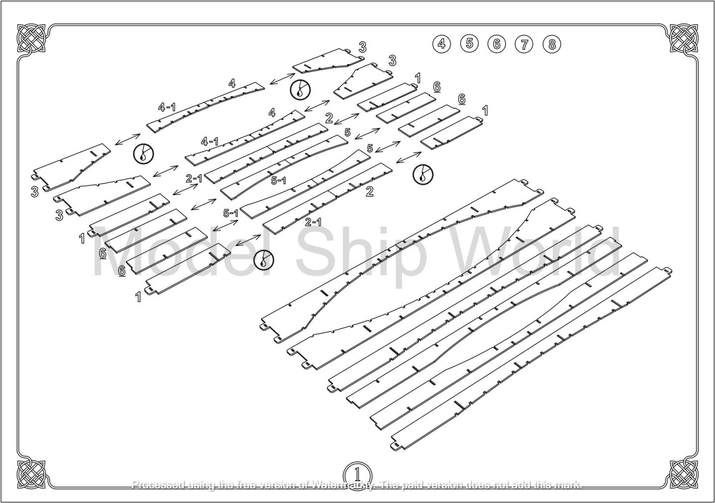
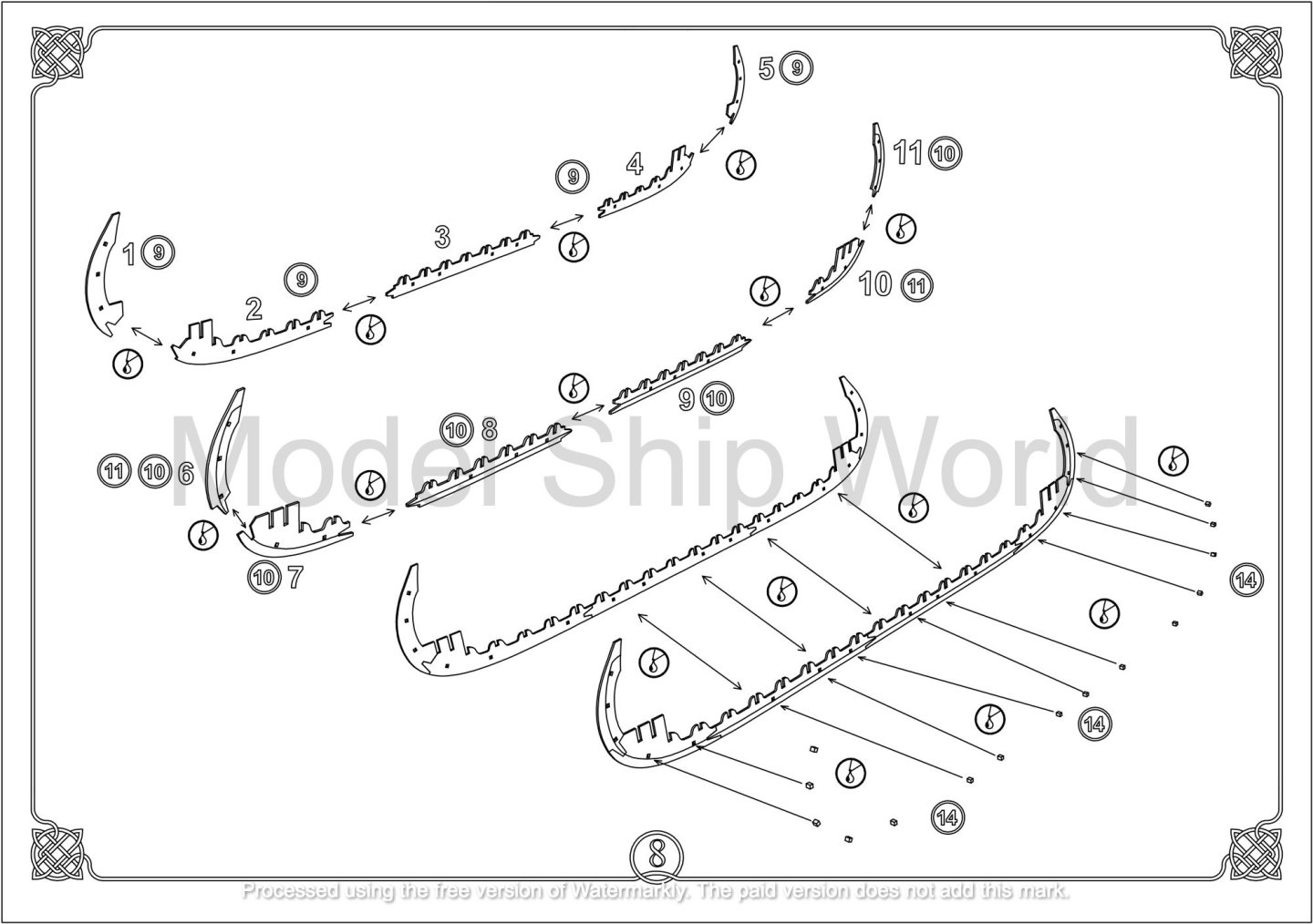
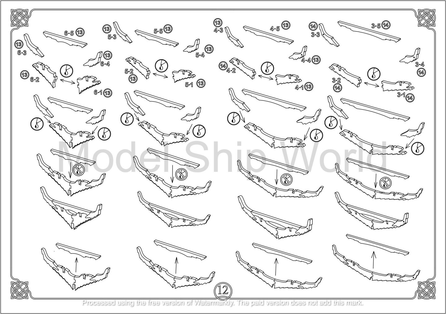
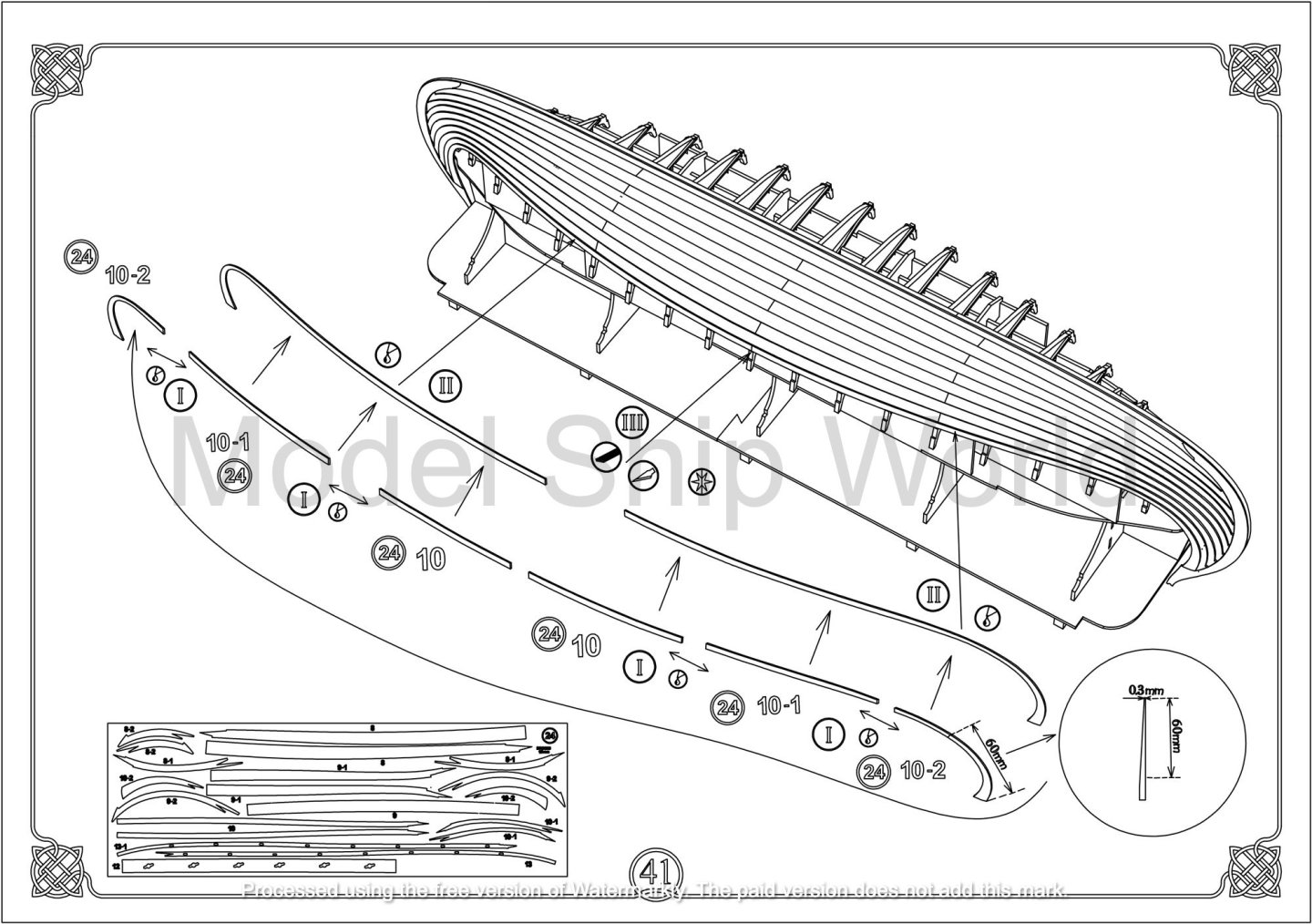
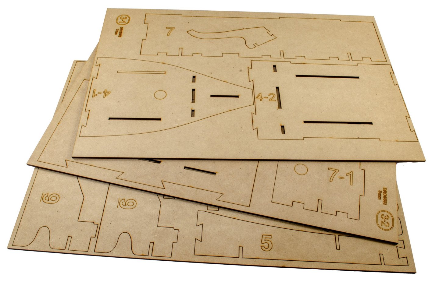
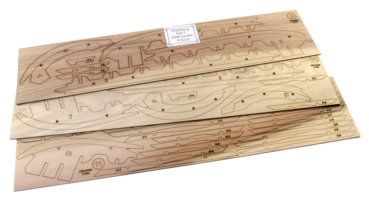
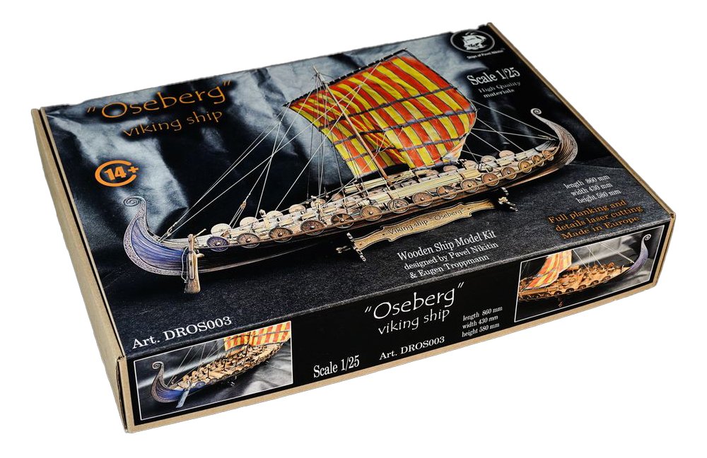
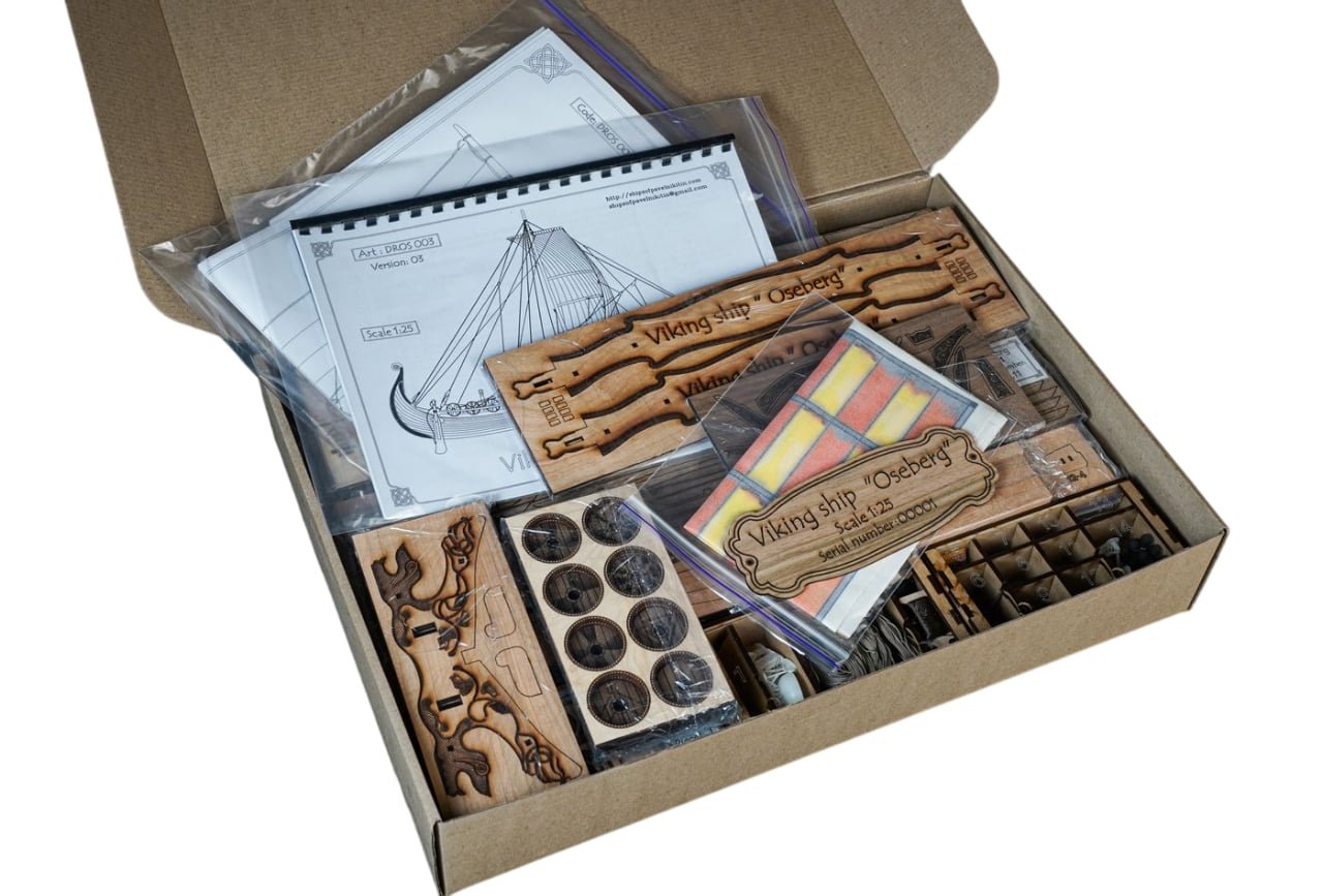
1:25 Drakkar ‘Oseberg’ V3 Ships of Pavel Nikitin Catalogue # DROS003 Available from Ships of Pavel Nikitin for €216,98 (at time of writing) History It is believed that the word “drakkar” originates from the Old Norse words “dreki” and “kar,” which mean “dragon” and “ship,” respectively. The warship acquired this name because the head of a dragon or another mythical creature (like Jormungandr) usually adorned the ship’s bow. The shape of the ship was also long and narrow, resembling a sea serpent. The Vikings constructed drakkars out of pine, oak, or ash wood. They used a special technique for splitting trees along the grain. They then watered the planks and held them above a fire to make them more flexible. The shipbuilders put the parts of the ship together with iron rivets and nails and bound them with cords and ropes. After that, they tarred the whole structure and caulked it by plugging holes and gaps and making the seams watertight. The sail was rectangular or square. It was made of sheep’s wool and covered with grease so that it didn’t get drenched. If there wasn’t a fair wind, the Vikings used oars – 20 to 35 pairs of them. In the Viking age, few ships could compete with a drakkar in terms of sheer speed, but drakkars were also very nimble. Thanks to the drakkar’s shallow draft, the Northmen could easily sail along rivers and fjords. They could land in places that were very difficult to access and attack their enemies unexpectedly. These warships were also barely visible between the waves because of their low sides. This helped the Vikings catch their enemies unawares, even in the open sea. Drakkars were created for more than just war, however. They were solid and capacious, so the Vikings sometimes used them for trade and to transport goods, but more often these ships were used for sailing long distances. How far did the Vikings travel? They reached the shores of Iceland, Greenland, and North America, to name but a few destinations. (Abridged from Vikings: War of Clans) The kit The first thing you must know here is that this kit is not a rehash of the V2 which we looked at here in March 2023. This is an entirely new design, from the ground, upwards. That needs to be stressed before I continue. If you want to know what makes this kit different, this is from Pavel's website: "The “Ships of Pavel Nikitin” presents a new version of the legendary Viking ship “Oseberg”. The differences from the previous version are so significant that it is essentially a completely new ship. There are lot of changes: the frame became almost like that of a real ship, the decks now have separate boards, and the hull plating is implemented differently, with all the textures running along the boards. The rigging of the ship has gained historical accuracy based on the scientific works of archaeologists. All the rigging blocks, are based on reliable sources of the Viking history and made of wood and are included in the set. Anchors and a galley printed on a 3D printer are also included. The kit comes with a sail painted in Viking colors. The model stand is made in the style of wooden construction and the carvings of the 9th-century Scandinavians. At all stages of model construction, auxiliary slipways and fixtures, which are included in the set, are used. The construction instructions consist of 73 pages in A4 format, as well as 4 very detailed drawings in A0 format. The number of pre-cut parts exceeds 1,900 pieces. The total weight of the set is an impressive 6.2 kilograms." V3 is still modelled in 1:25, and there is an extra price premium to the V2, with this costing around €70 more than its predecessor. In fact, the V2 is now no longer available, and this new kit carries over 2kg more in materials and of course is packaged into a larger box to cope with that. That box is indeed quite large and there's definitely some reassuring weight to be had with this kit. Pavel Nikitin’s newly re-designed kit is still the largest in scale of this iconic vessel, recreated in at a whopping 1:25 scale! That equates to the following sizes: Length: 860mm Width: 430mm Height: 580mm I know from experience that if you remove all these contents, you'll struggle to fit them all back in. In fact, I decided to leave out the MDF pack so I could start on building the first cradle, and still the box looked very full. Like the previous release, this kit is manufactured in several different timbers, namely alder, walnut, cherry, and beech. The kit's sheets are also divided up into various packs which have a cellophane wrap on them, and an identifying slip of paper which denotes the sheet number, which is as well as there are MANY sheets in this kit. There are not one, but two cradles/jigs in this kit, with there being THIRTEEN sheets of 3mm MDF for this purpose. The reason for two cradles? Ok, that's easy. The first cradle is simply a large framework into which you will sink the assembled keel, and then install the multipart bulkheads. Once this is complete, and the stabilising longitudinal strips are installed, the hull is removed from this jig and then transferred to the second one, where it will then be placed upside down whilst it is then planked. Later, the hull can then be turned the right way up and reinstalled in the same job while work further commences. These jigs are also large, as I can attest to at the moment. you'll see those in my build log which will begin soon. Even though these are the last thing to be built, you can see the numerous sheets that exist for the display stand. I'll build this quite early on and then set to one side, just to reduce the number of sheets of parts! I included a 6 inch steel rule in the photo, so you can get an idea of the scale of the completed item. There is some variation in the colours on these sheets, but looking at the parts, this would mostly affect areas that will be hidden under the deck area. This doesn't duly concern me. The laser cutting is also fine, with identifying numbers which are in areas that won't be seen on the completed model. The multipart bulkheads have engraved lines denoting but they should be tapered to accommodate the external hull planking. All of this is also explained within the manual. In this photo, the parts for the rudder and laminated mast fish (base) are clearly seen. Here you see the deck panels. These are actually individual parts and with some imagination, you could probably pose a number of these so you could see the area below deck. These parts are all hull planking. You can see the section will be keyed together with a scarf joint to create the whole lengths. More very shortly....


- 14 replies
-
- 12
-
-
-
- Pavel Nikitin
- viking
- (and 2 more)
-
Brilliant to see it done, and so quickly too. Excellent work!
- 62 replies
-
- 3
-
-
- belle poule
- OcCre
- (and 1 more)
-
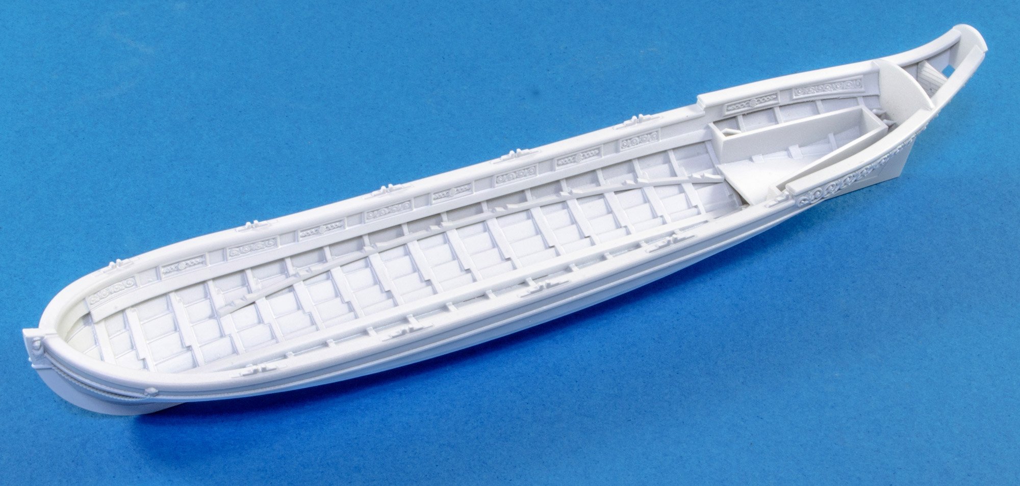
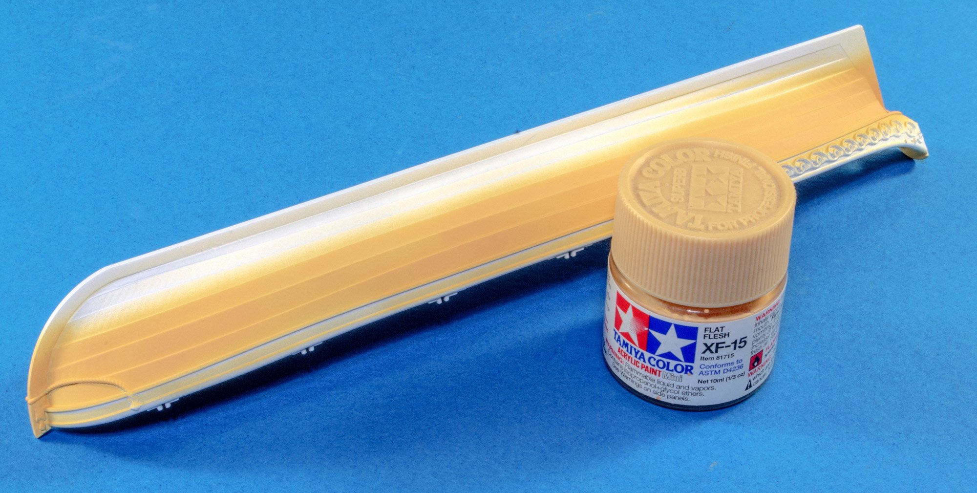
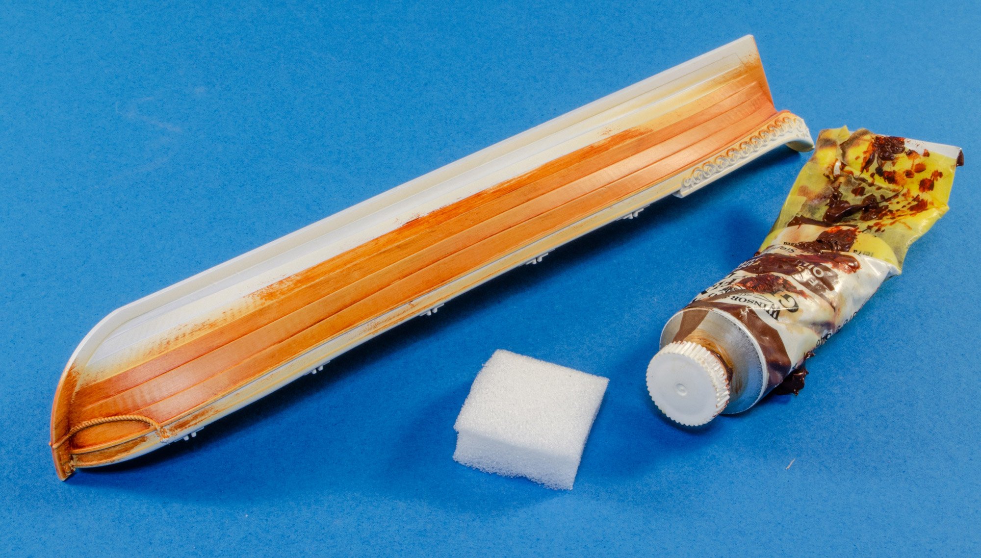
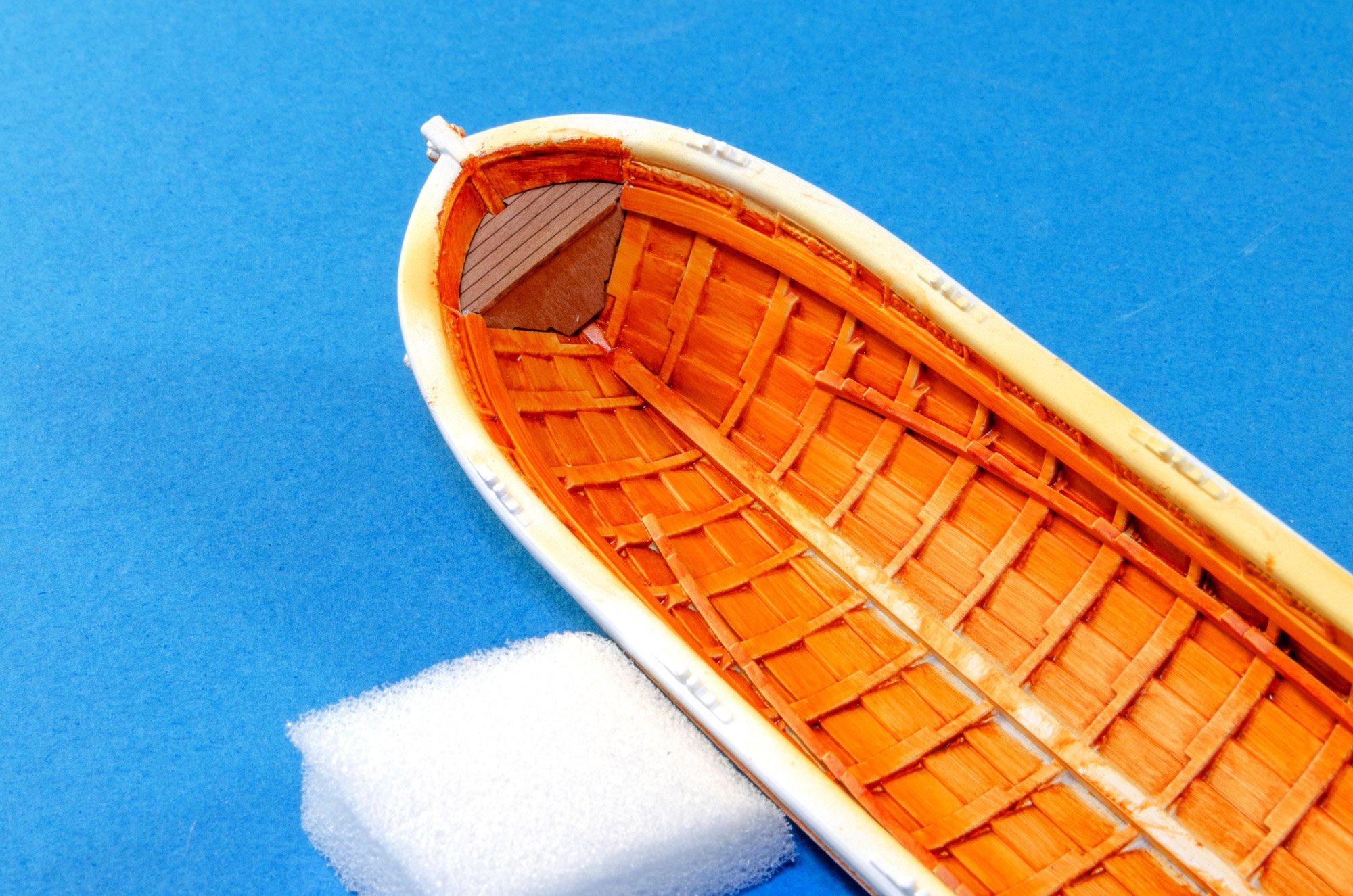
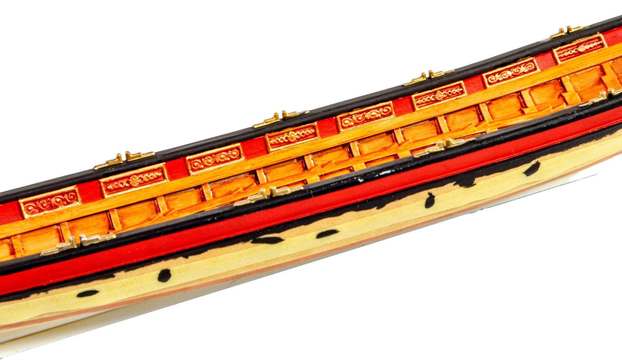
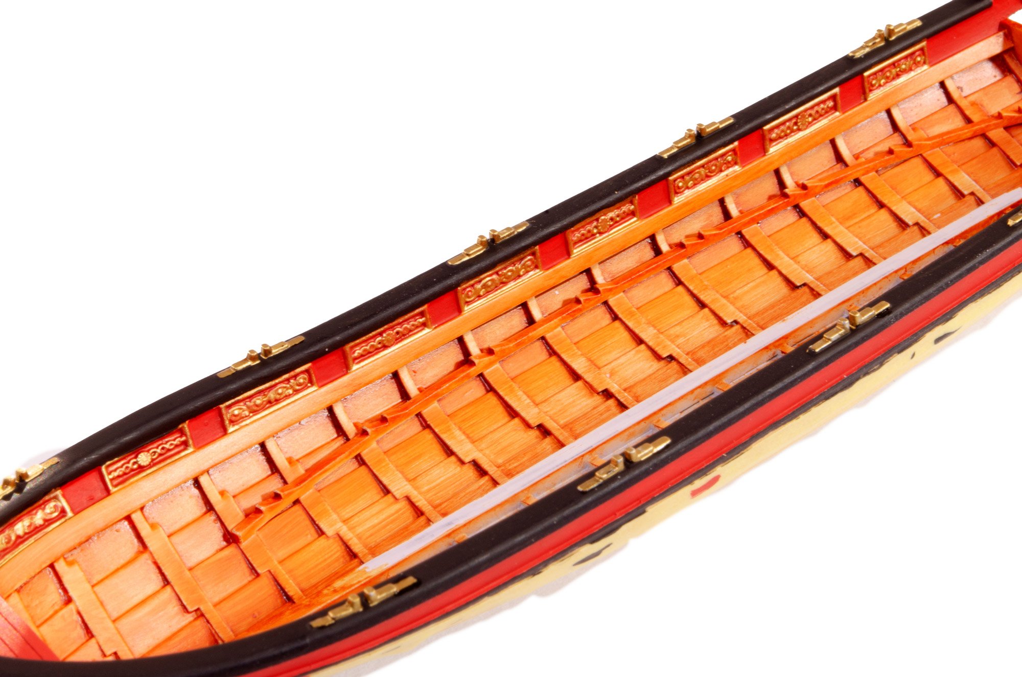
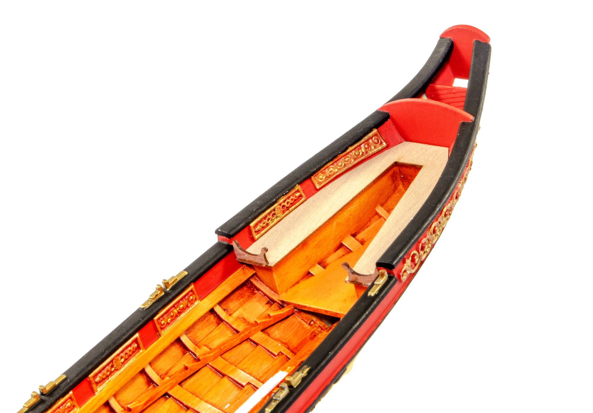
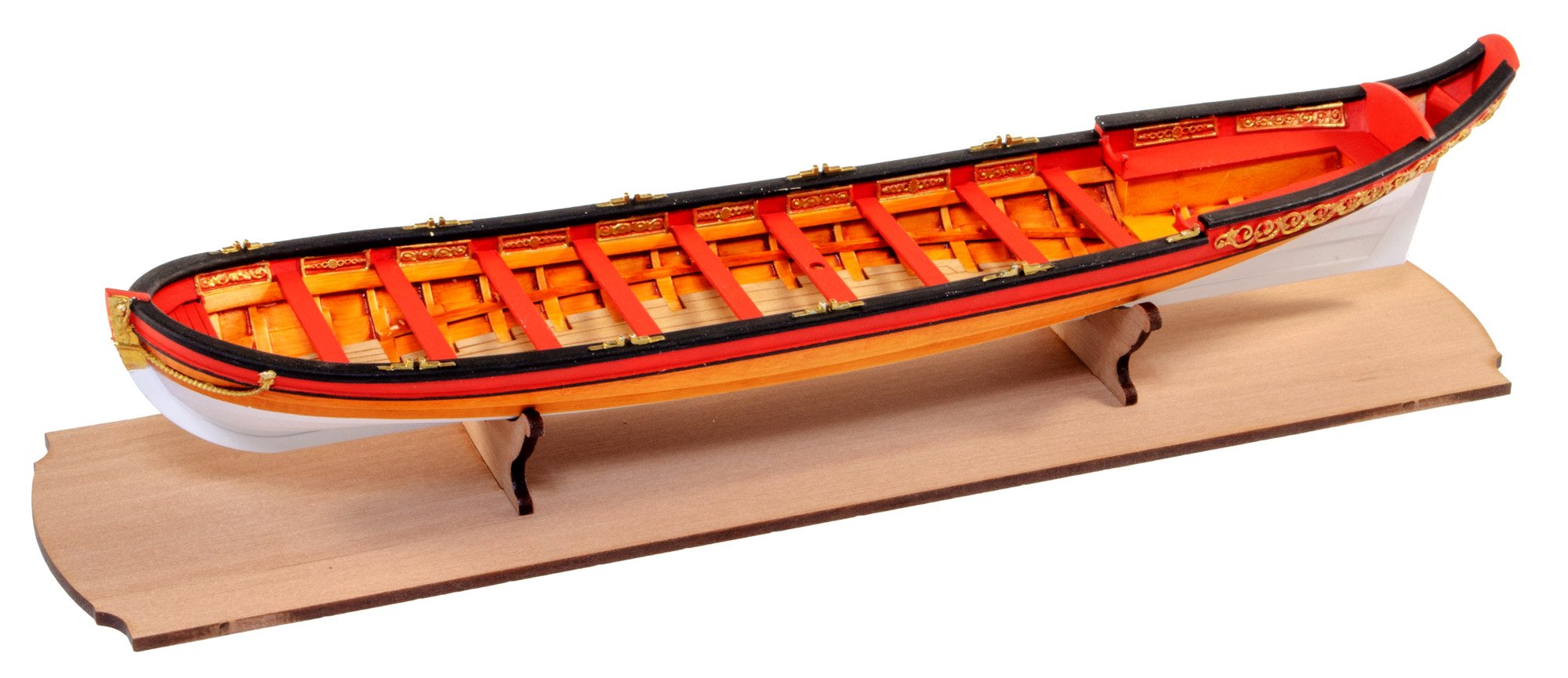
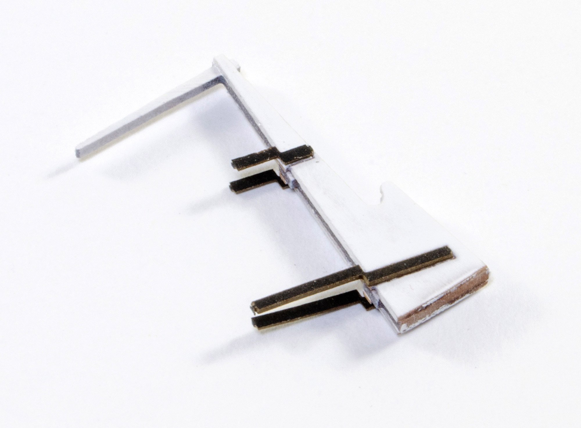
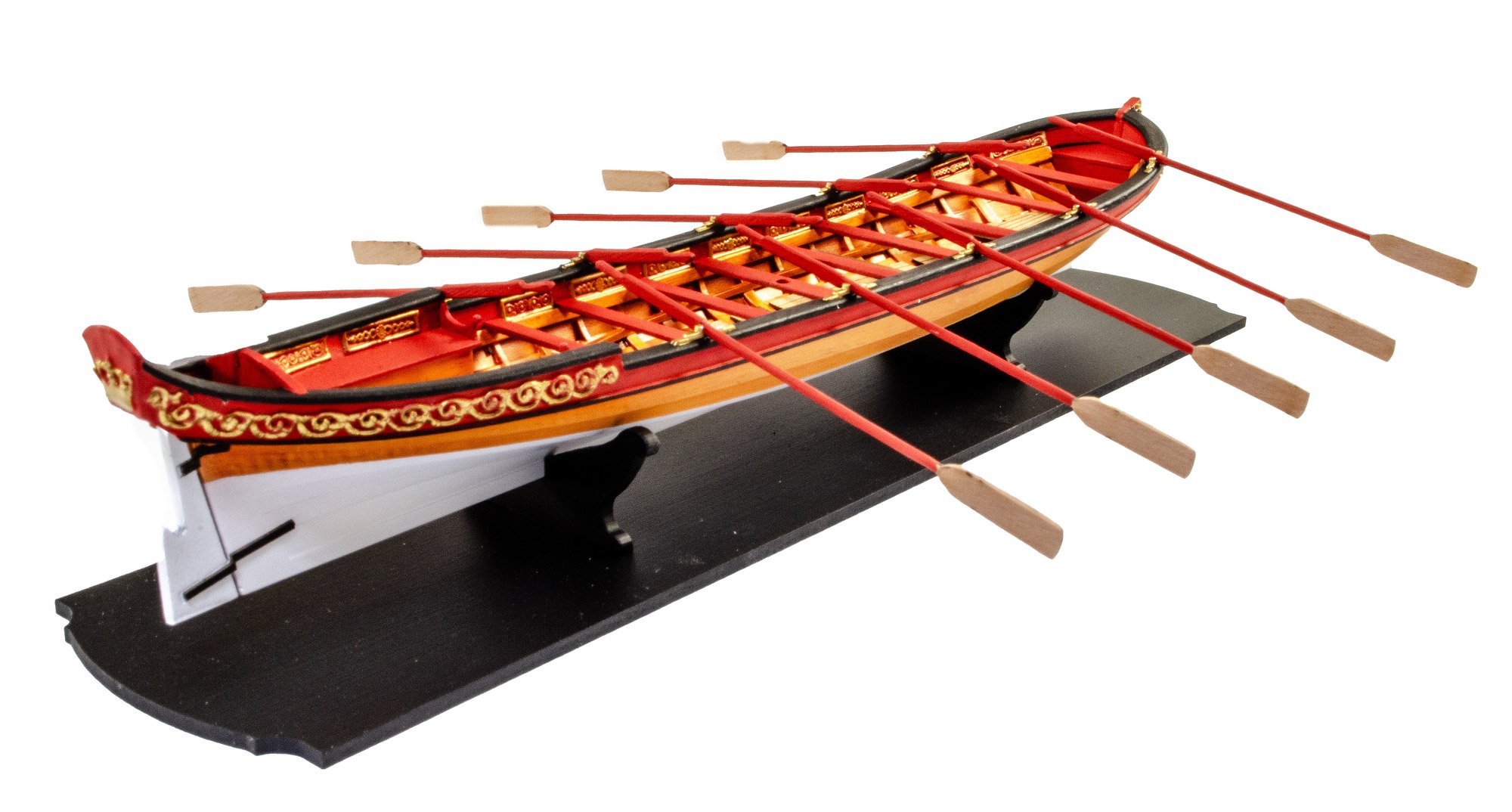
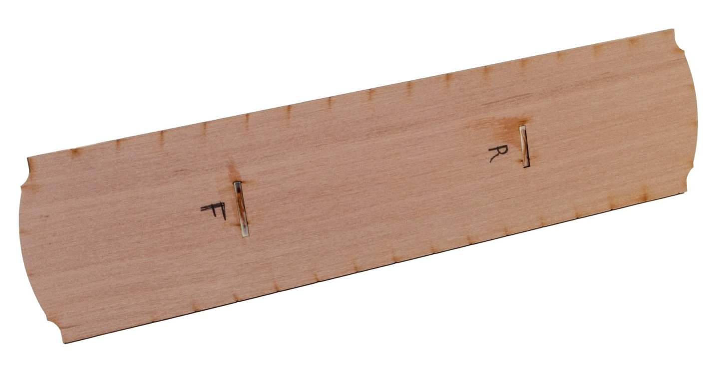
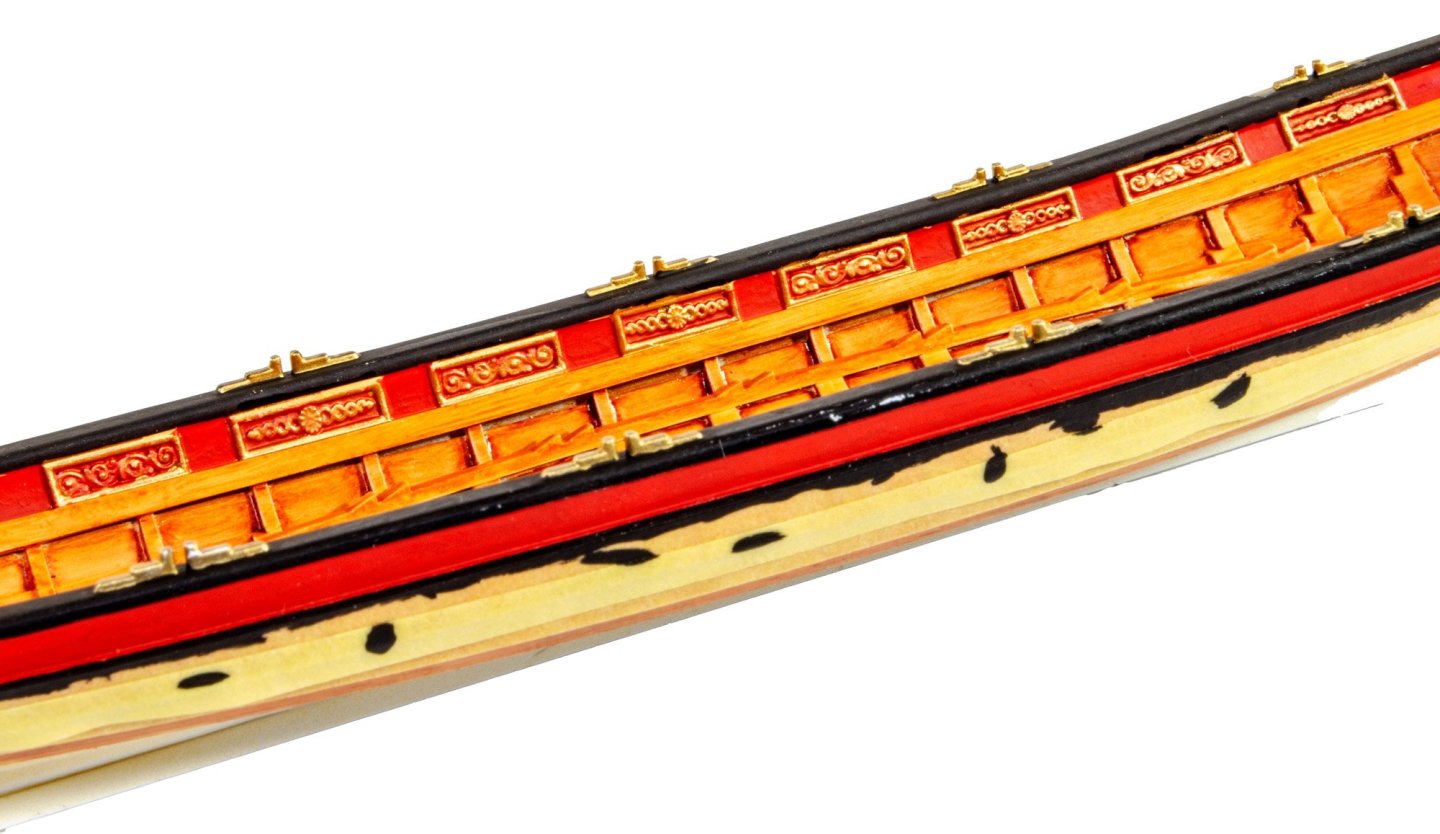
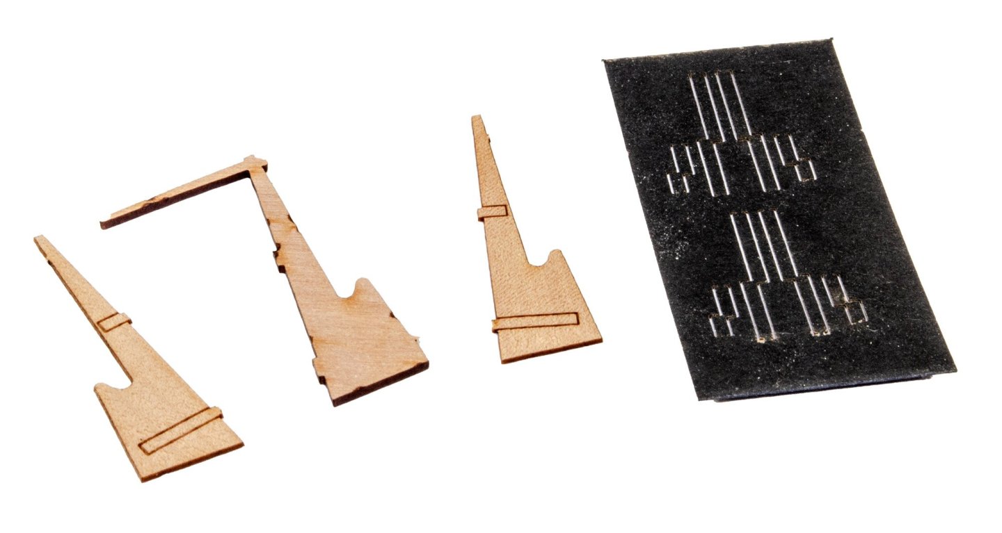
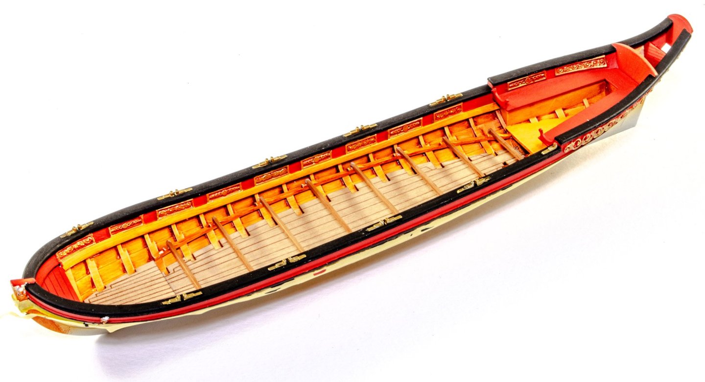
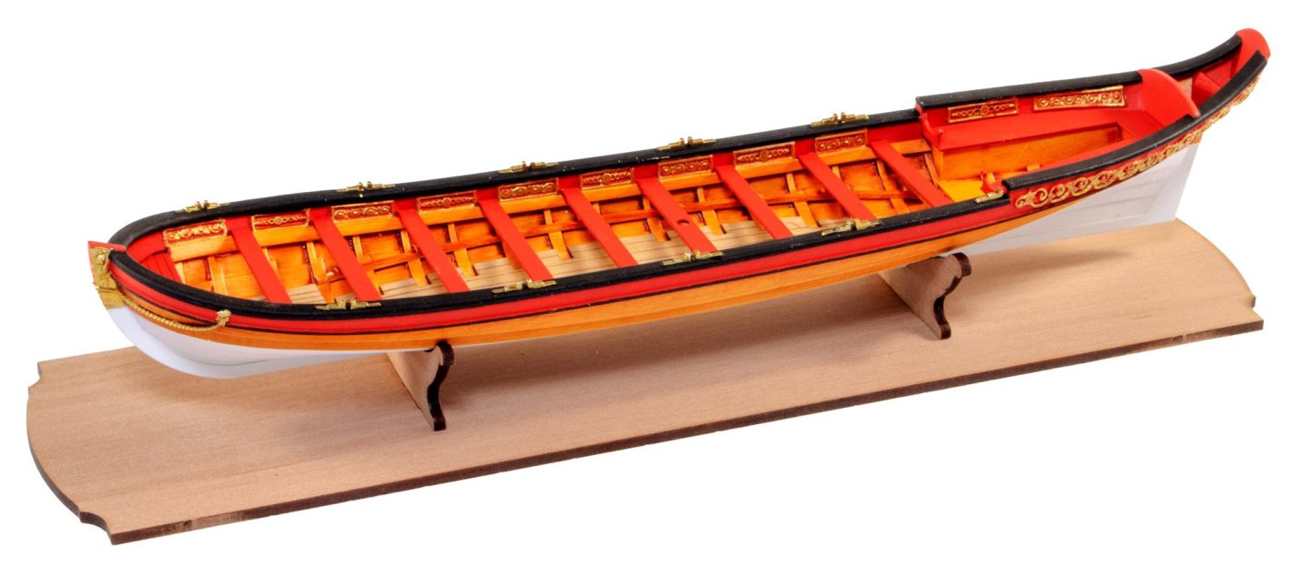
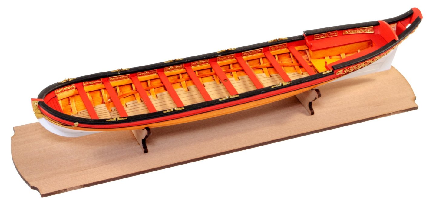
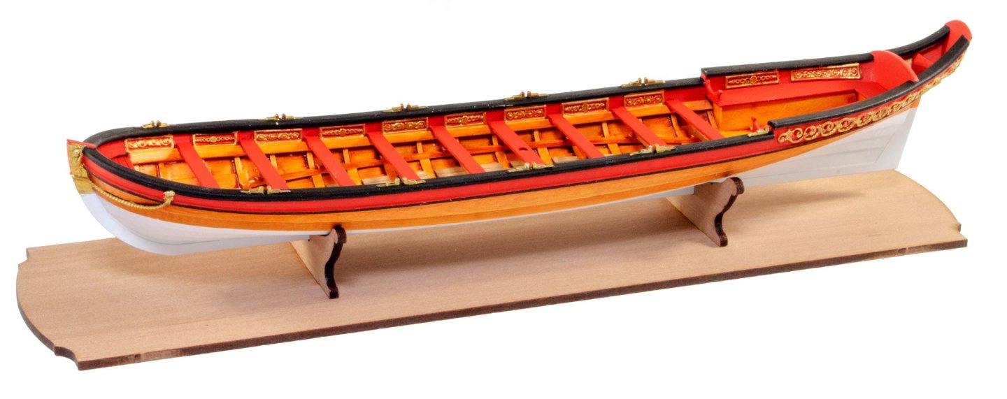
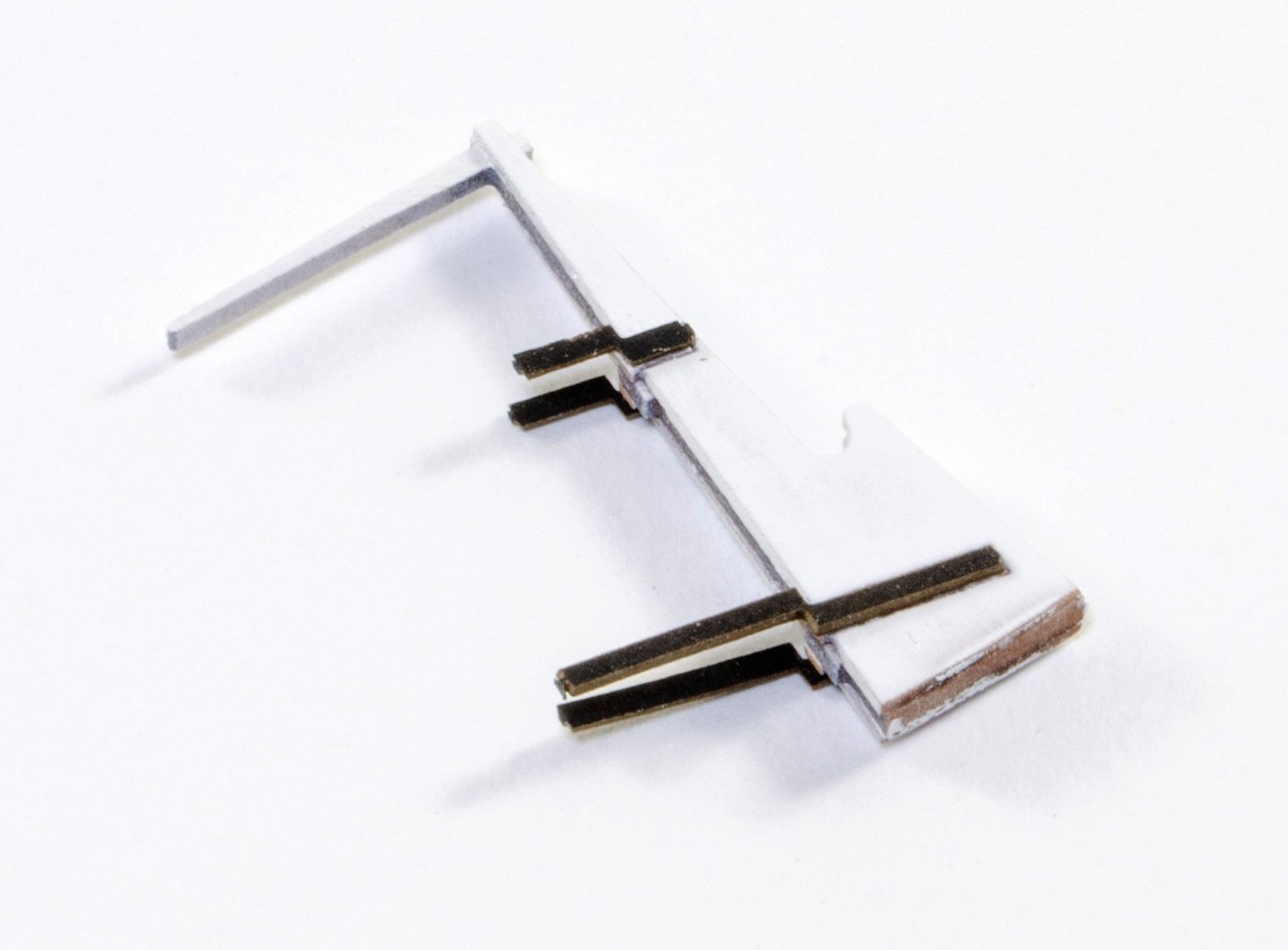
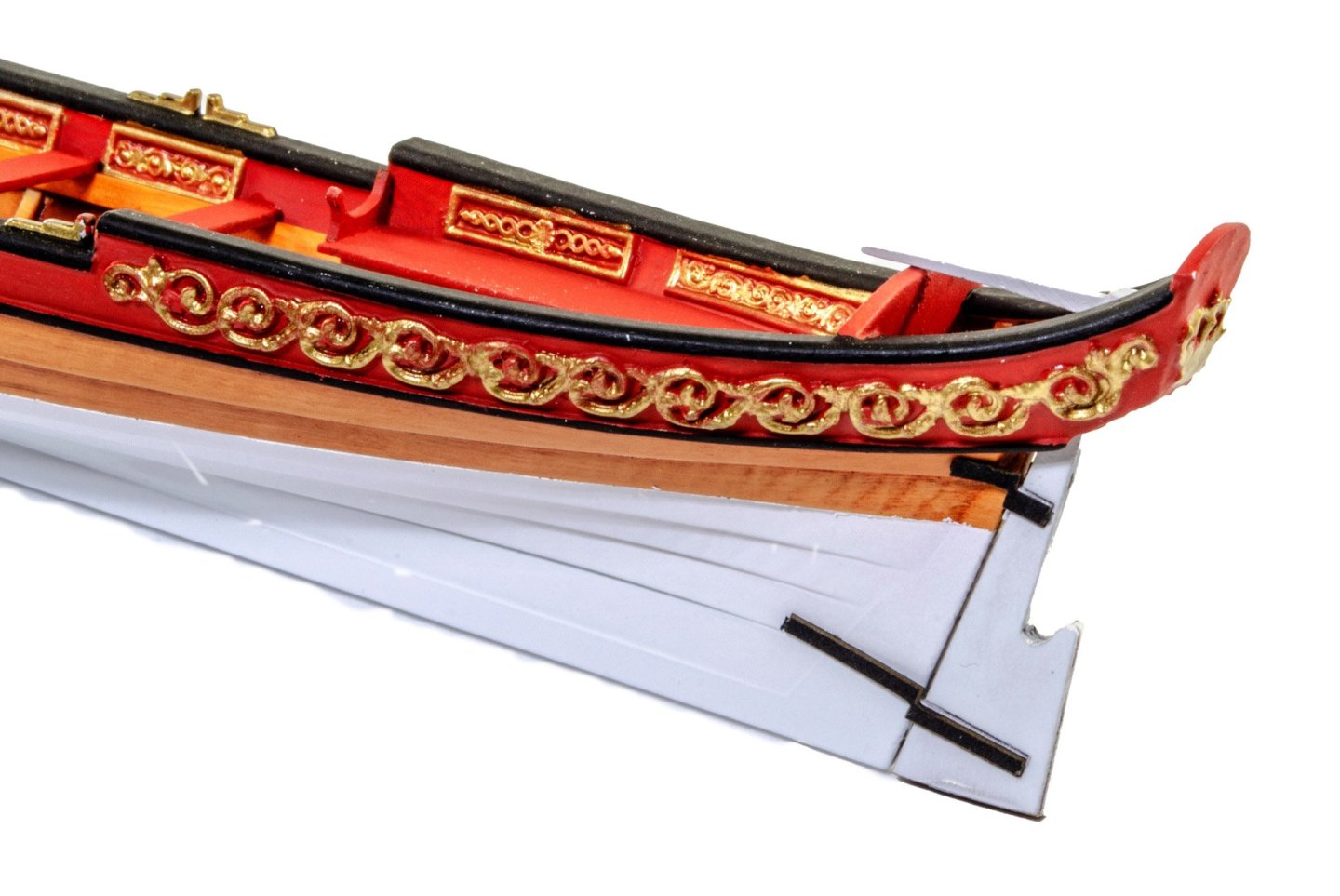
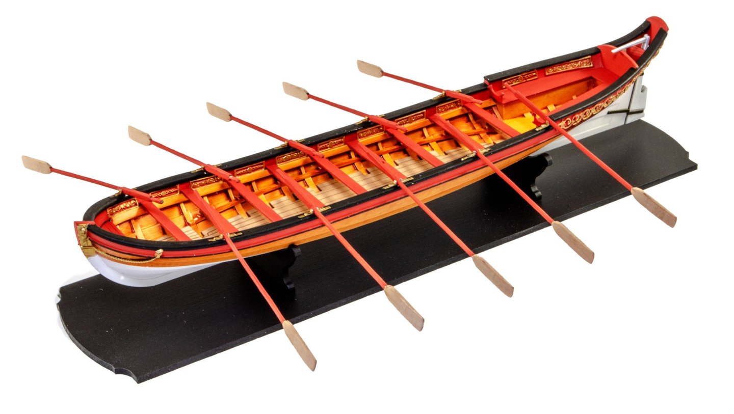
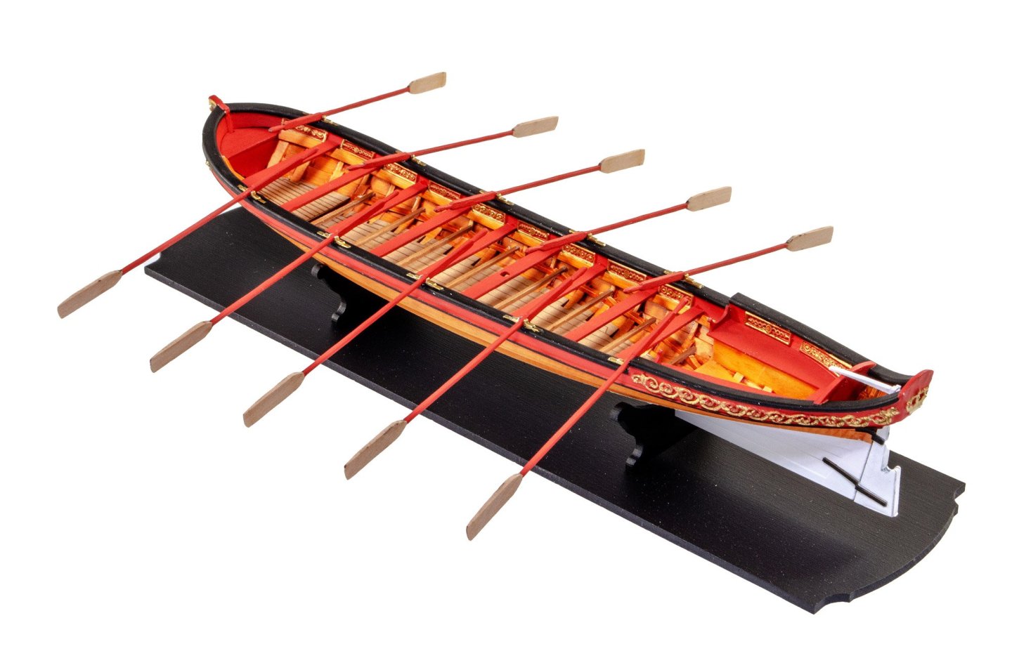
Ok, this log is going to be very brief as it simply highlights the work I've done over the last week. The subject of this is the 33' Royal/Admiral's Barge that I've built for the Vanguard web store, hence why this has been brief. The kit itself has been designed using Admiralty drawings and has minimal construction save for the essentials which would otherwise impede the painting job you'll need to do. The hull is very much complete and is printed in 3D. The hull is printed in grey resin, and they are ultrasonically cleaned. It's still prudent to prepare the surfaces with a good quality primer. I use Tamiya Fine Surface which etches itself into the surface to create a stable base for your paint. Now this is where, in my opinion, I went wrong. The hull needs to be painted to represent a wood colour, and my choices wee too 'orange' in appearance. If I was to do this again, I'd use Desert Sand Yellow instead of Flesh, and a warmer oil paint. The grain is created by dragging the oil over the acrylic base colour, using fine sponge. The first timber parts are now added to the bow, with the vertical part needing bevelling on the rear face. This can now be painted in red. The hull now has the exterior wood finish masked off. For this model, there wasn't a waterline added, but instead the first two lower strakes are masked off. You can see I used the tape for a convenient place to remove excess paint while painting the black and red colours. The internal panels require a tactic to make sure they are properly painted. Firstly, they were entirely painted in gold. When dry, the red was added as a thin red wash which floods around the lower areas of the relief. Cheating? Yes, but the results are easy to obtain. Paint is removed from the inside keel so that the pearwood floor will adhere properly. The rear seating is now fitted, along with the two parts which sit at the end of the seating. All this is now painted in red. The floor is now fitted. Breaking off the hull to get the base built. This is simple, and the supports are handed, so there's a front and rear. I mark which is which on the underside of the base. You can leave this in natural pear, or paint in a suitable colour. For mine, I decided to blast it in Games Workshop Chaos Black spray. The rudder is made up as a typical sandwich. This is then painted and the card hinges are fitted. These hinges are only applicable to the 1:48 version. The rudder is now fitted and the other end of the hinges glued to the model. The oars are now shaped and fitted to the model. I sat a sanding sponge along each side of the hull in a suitable place so that the oars could droop onto it evenly along the length. And that folks, is it! My shortest build log, but you may find it useful if you wish to build this gorgeous little model kit.


- 4 replies
-
- 25
-
-
-
-
- Admirals Barge
- Vanguard Models
- (and 2 more)
-
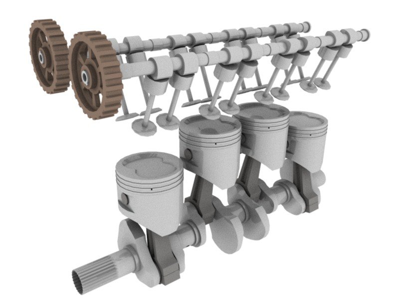
build review L4 Engine - Teching - vie EngineDIY (Build Review)
James H replied to James H's topic in Non ship-related reviews
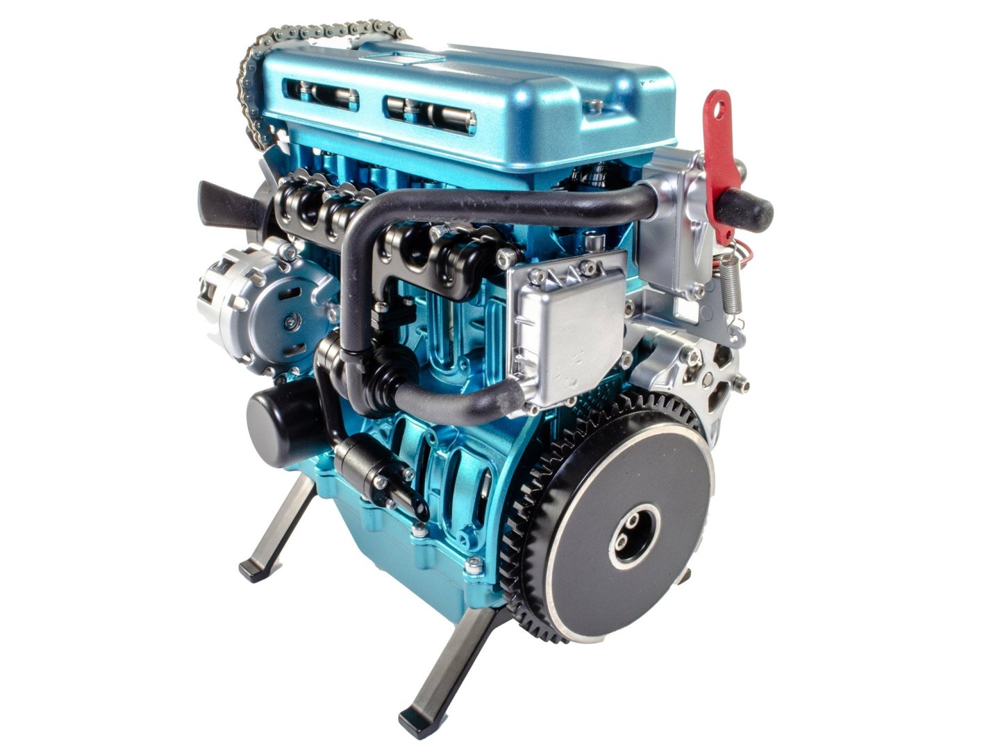
Finally, here is the video of the engine running. It does actually sound a lot smoother than is heard here, and you get an idea of that when I rotate the engine whilst running. Conclusion I was a little concerned that this engine would be very close to the V8 engine that I reviewed a few months ago, but I needn't have worried. The L4 is a totally different beast, and I don't just mean it has 4 less cylinders. This is an easy model to build and setup. I think it took me about 4hrs in total, including a refreshment break! Parts quality is absolutely superb, with everything fitting with total precision. This would be ideal as an introduction to model engine building, even with the caveats I mentioned regarding the instruction manual anomalies. If you are looking to start your collection, or just want something to sit on your executive desk, then definitely consider this kit! My sincere thanks to EngineDIY for the opportunity to build this engine here on MSW. To purchase directly, click the link at the top of the article.
-
build review L4 Engine - Teching - vie EngineDIY (Build Review)
James H replied to James H's topic in Non ship-related reviews
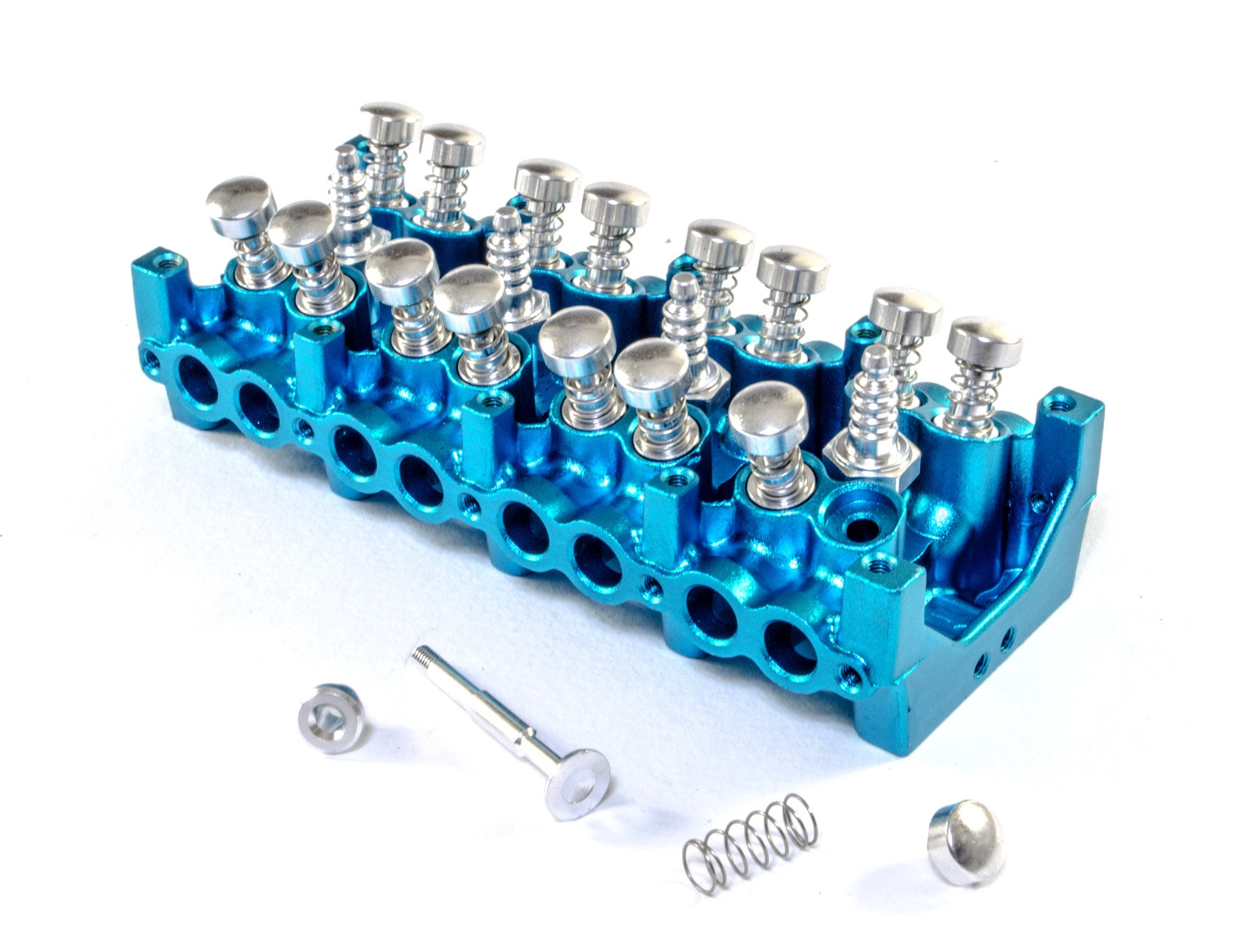
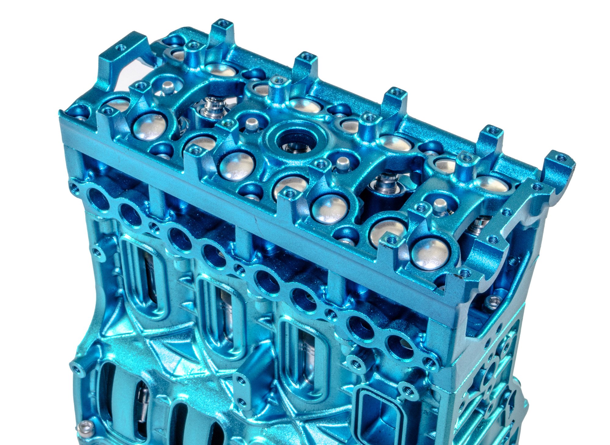
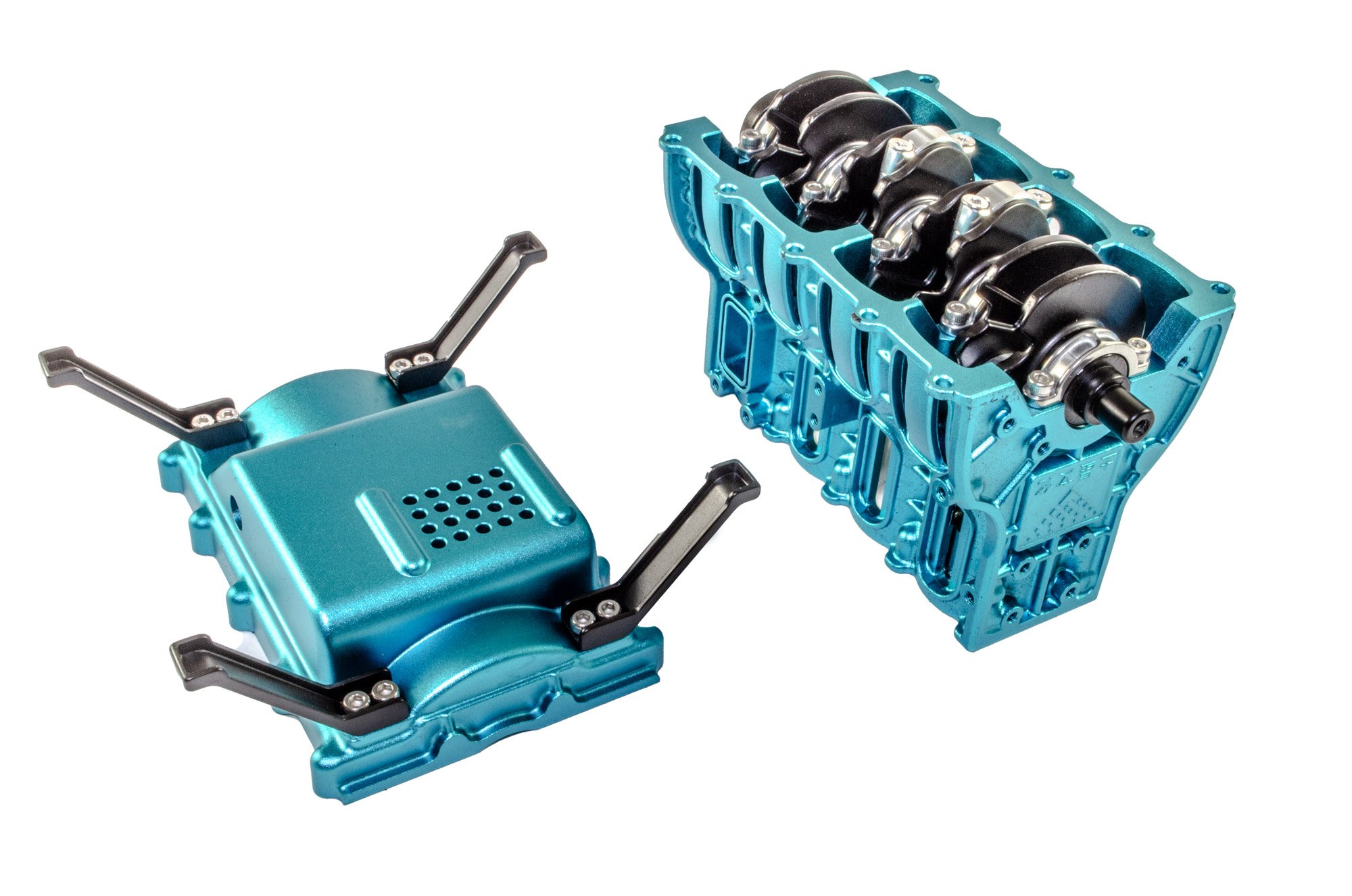
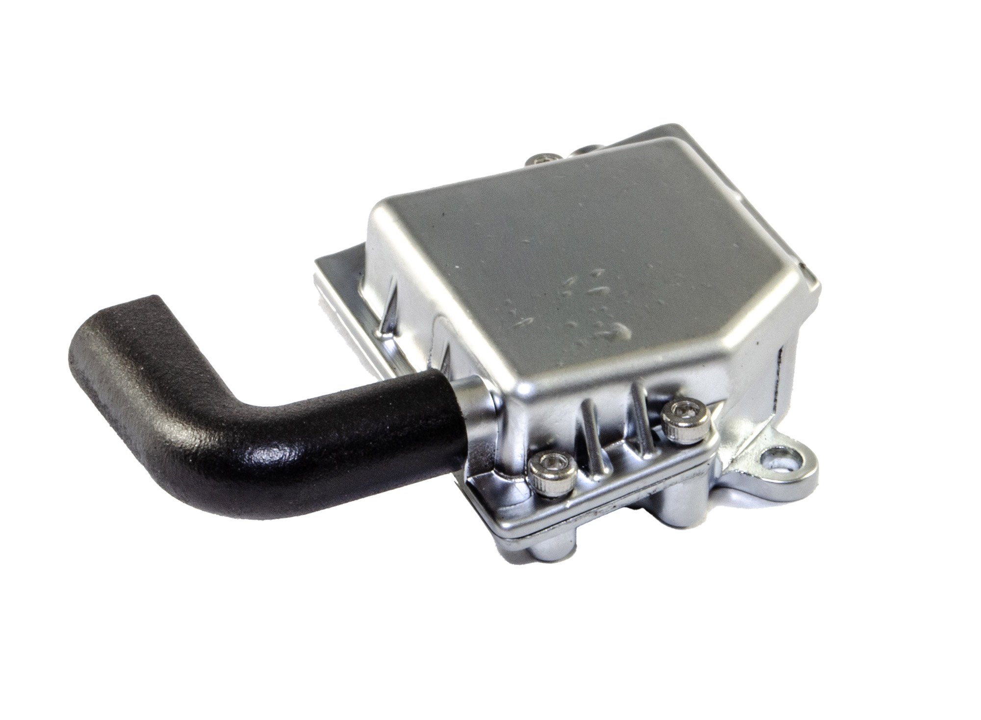
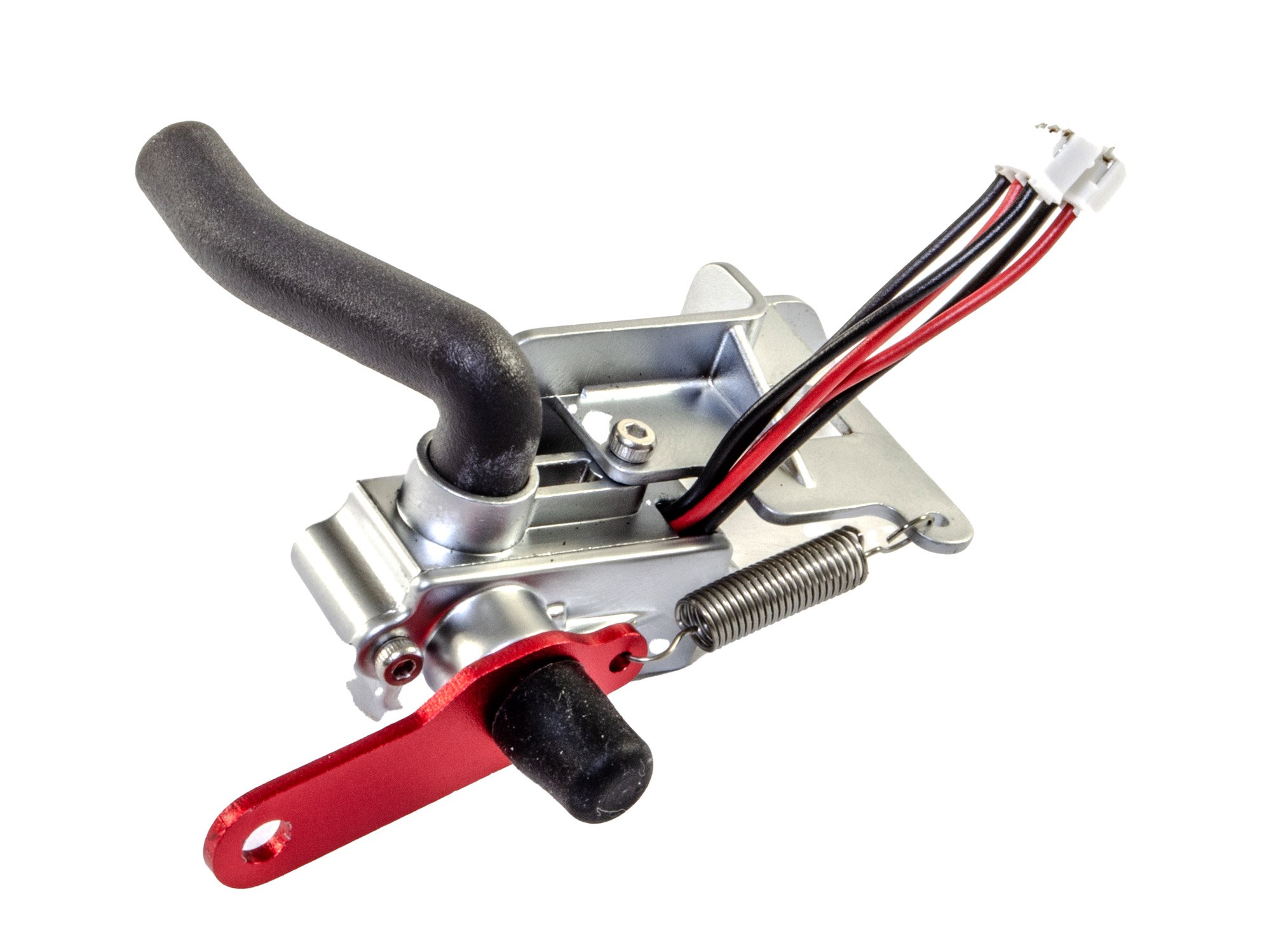
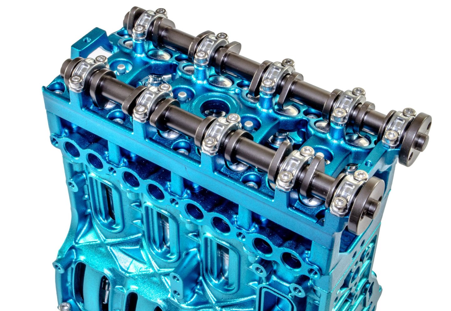
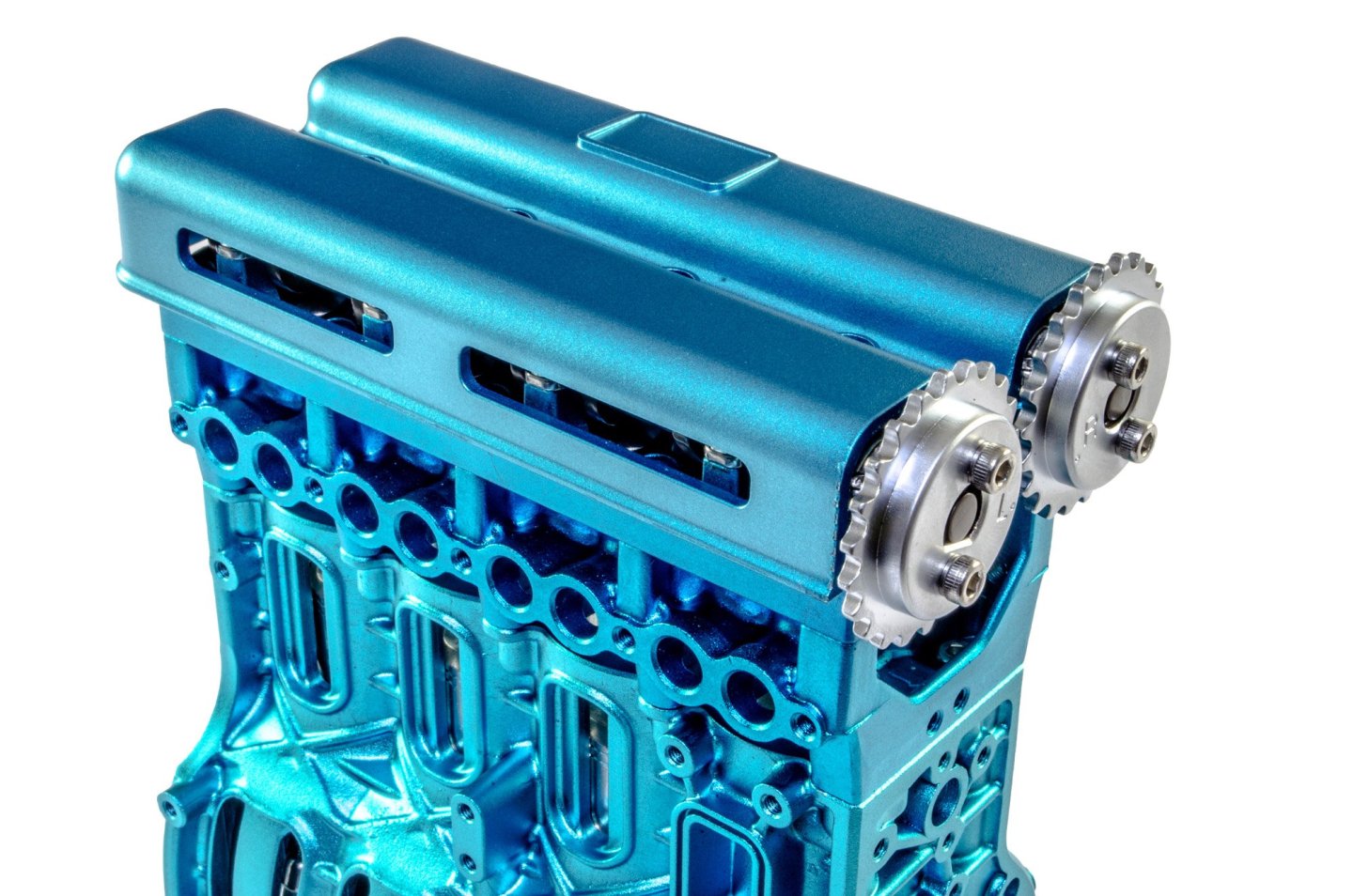
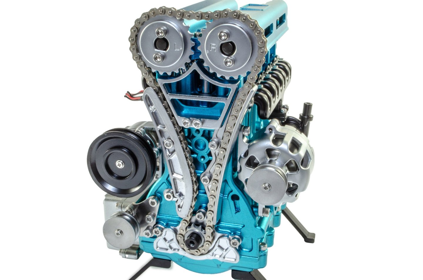
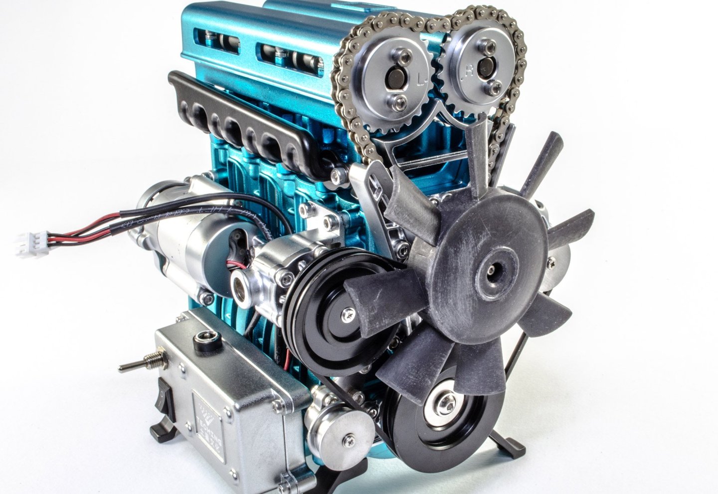
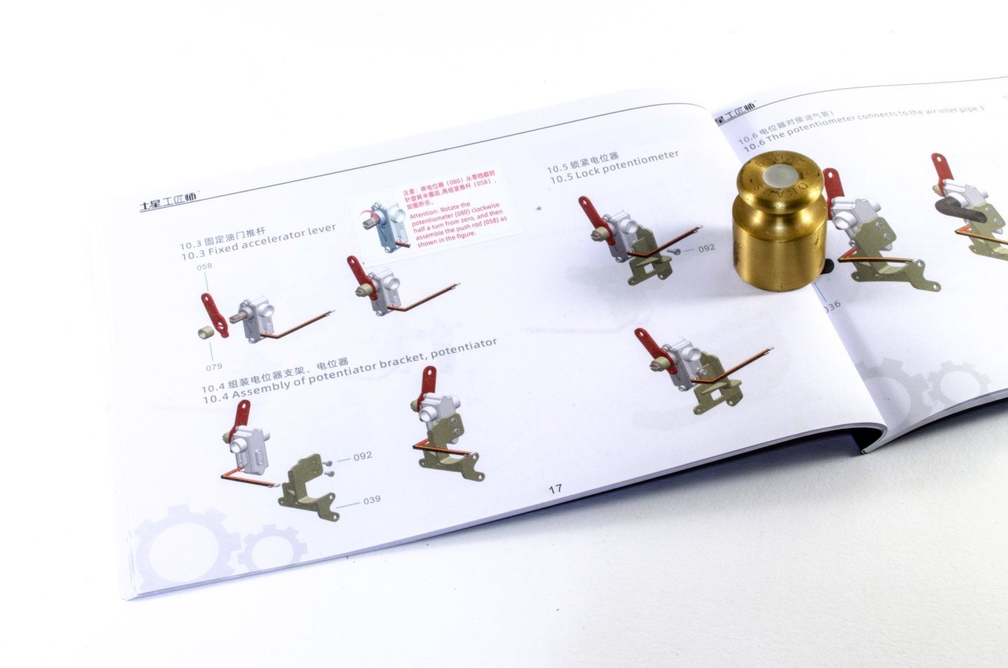
At this point in the build, the cylinder head is to be built. First, I add the four spark plugs, seen here in silver. Now, the pistons are fitted, with some light oil as lubrication. The manual tells you when this is to be added. You'll need to source your own lube, at least if you live in the UK, as it's omitted from the kits I've built. The cylinder head case is now fitted, and the whole assembly bolted to the crankcase. Of course, this engine will need two camshafts, and here they are, bolted in position and lubricated. When secure, the valve cover is installed. The control box is now bolted to the crankcase and the electric motor also fitted. The cables from this and the circuit are now routed into the control box. The belt pulleys are now fitted. Setting up the engine timing is a breeze. These two gears need to be set as thus, with the two pips aligning. The lower gear just needs to have a pip aligned with a mark on the crankcase. With that satisfied, the drive chain is now added, along with the track and tensioner. I found the midway point to be good for setting up the chain tensioner, so the belt and everything moved freely. Now the fan belt. Followed by the crankshaft pulley and the accelerator potentiometer. The engine is now completed! The conclusion and video will follow over the weekend...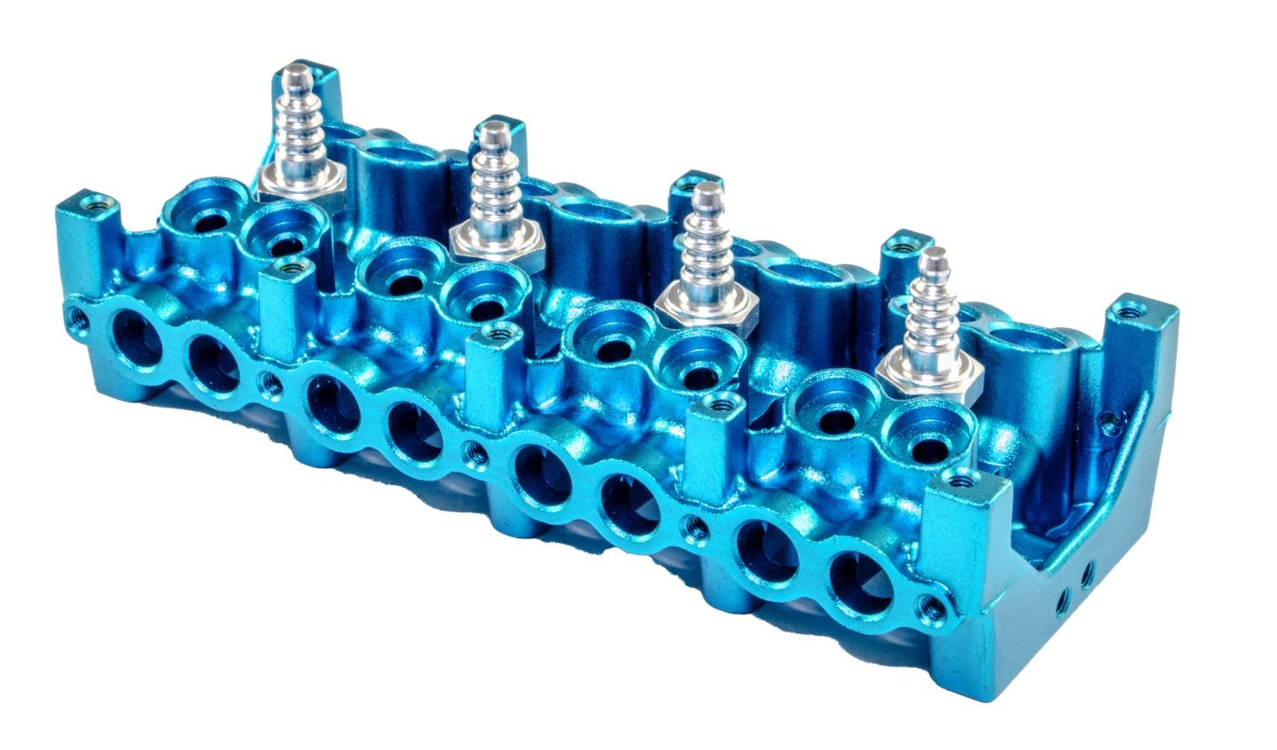


-
build review L4 Engine - Teching - vie EngineDIY (Build Review)
James H replied to James H's topic in Non ship-related reviews
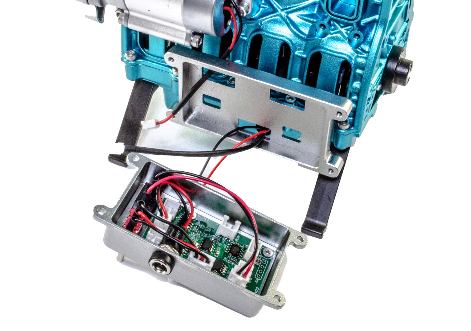
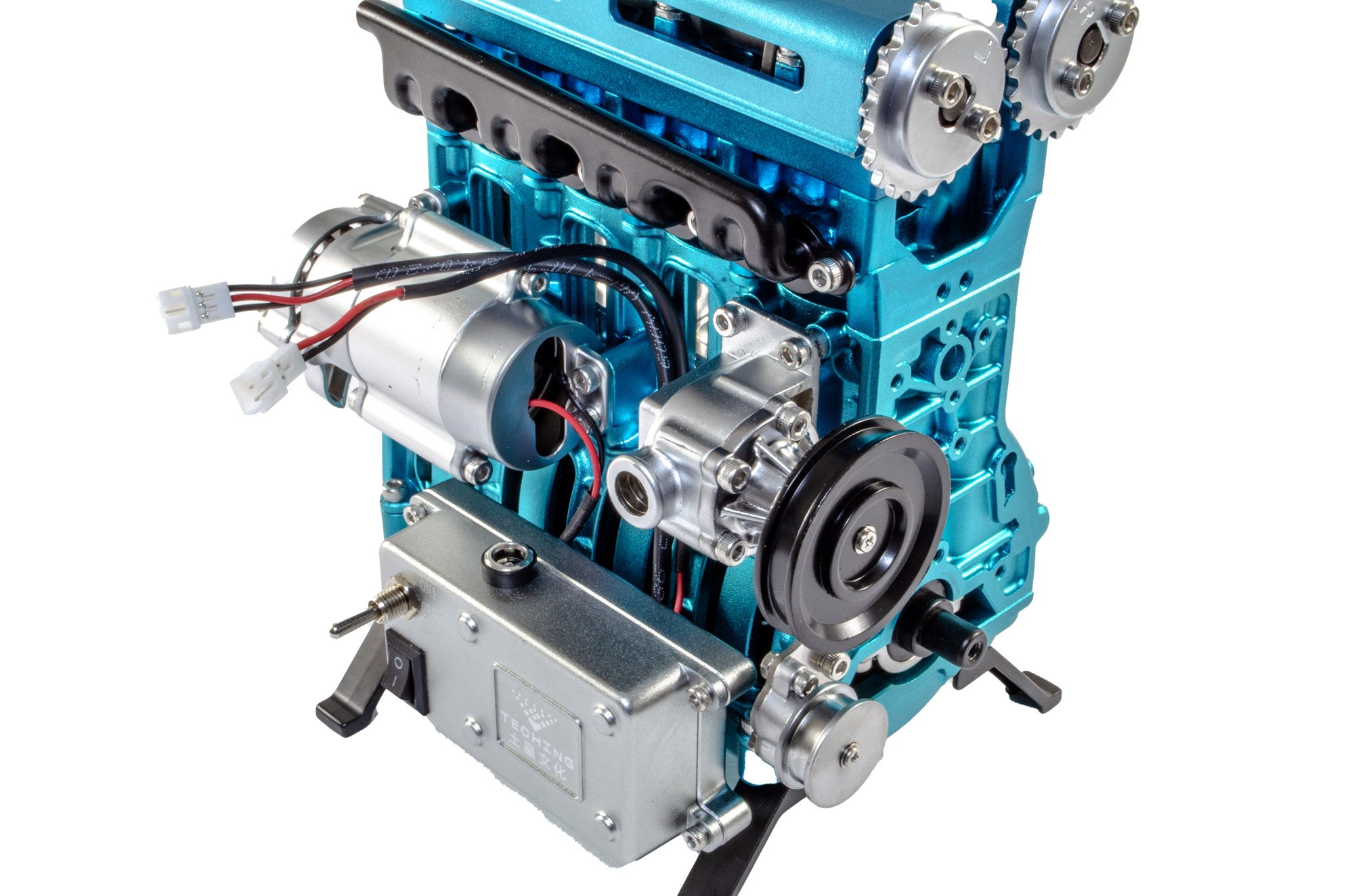
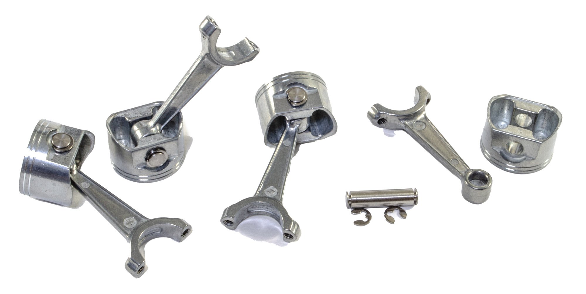
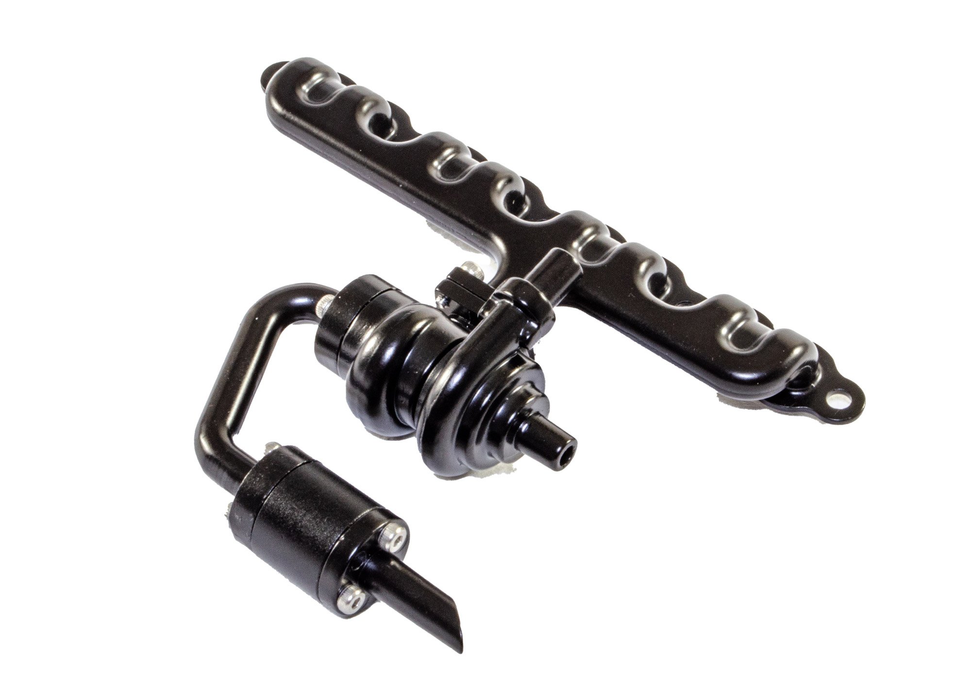
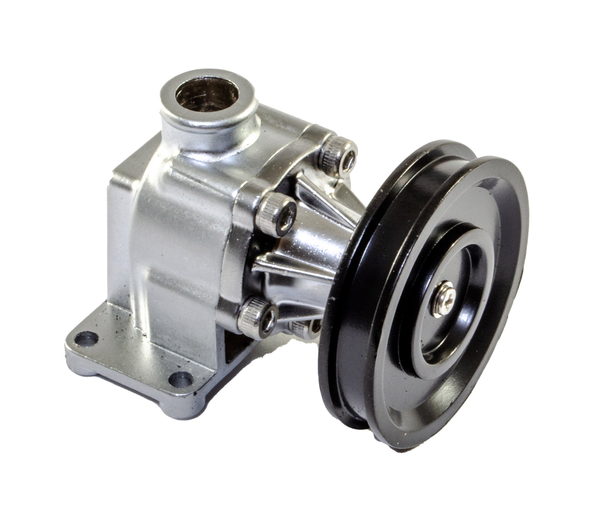
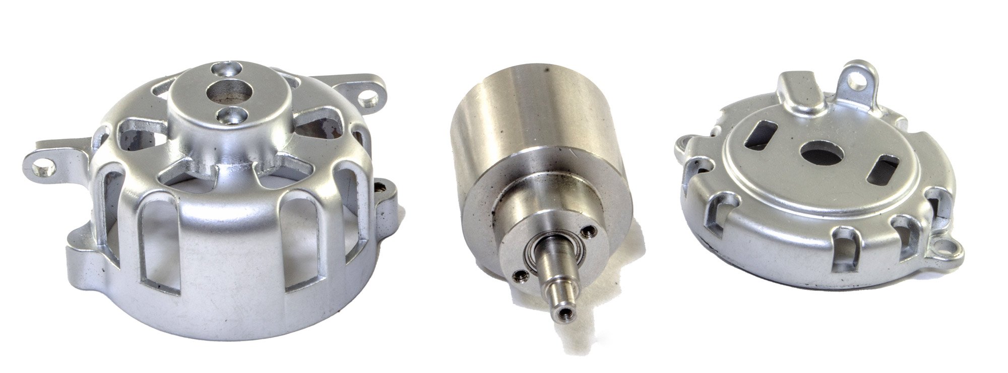
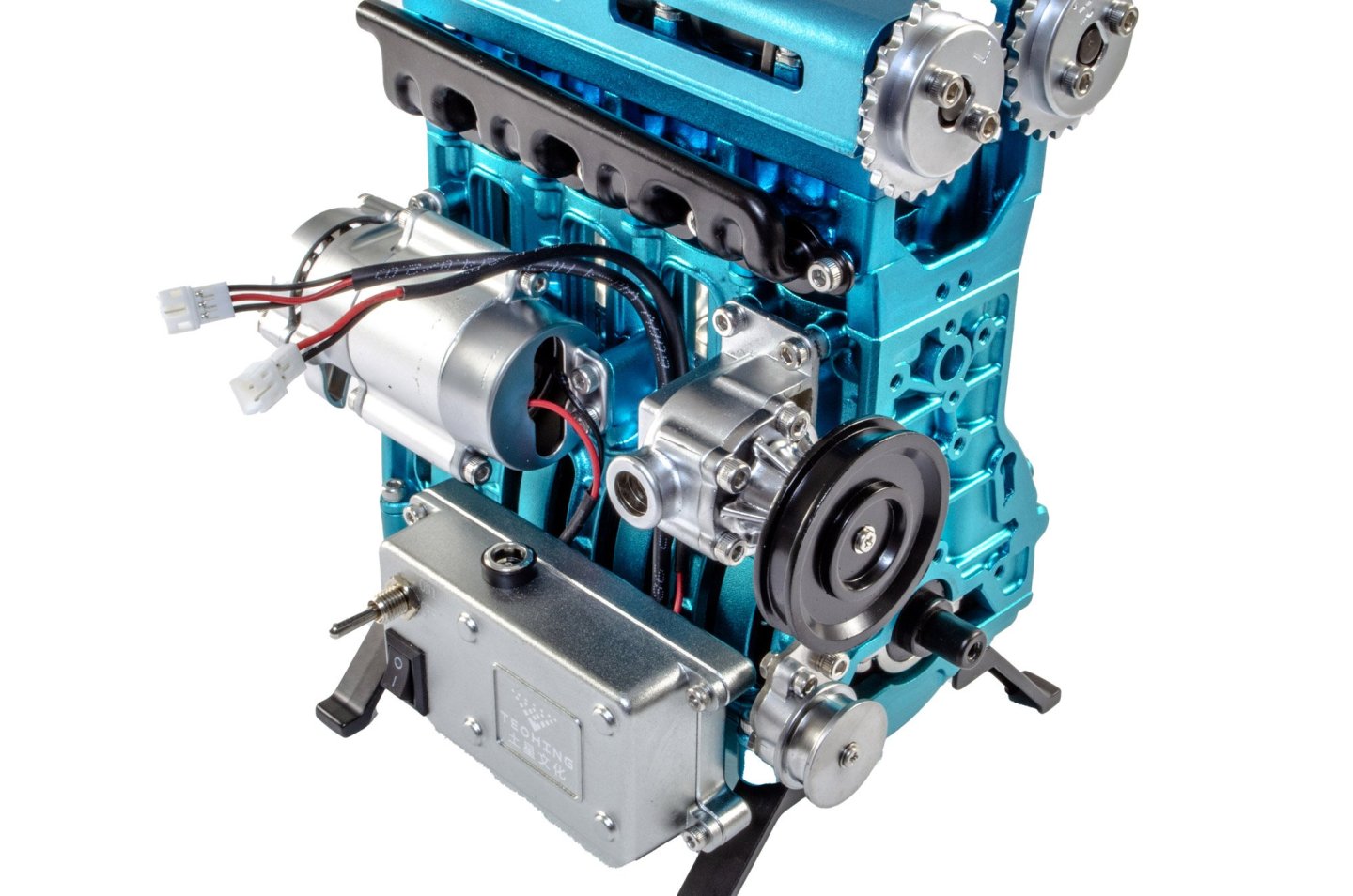
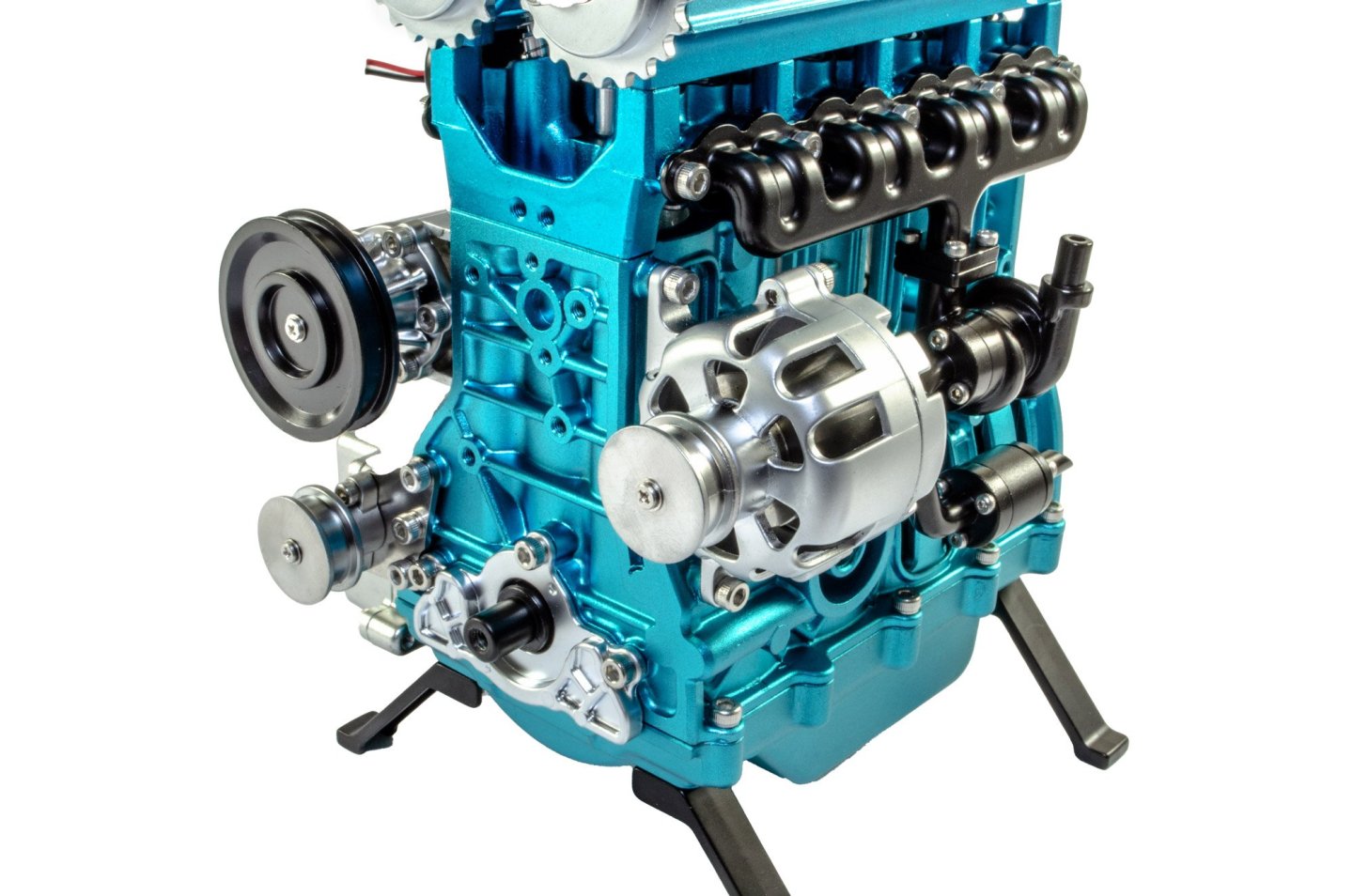
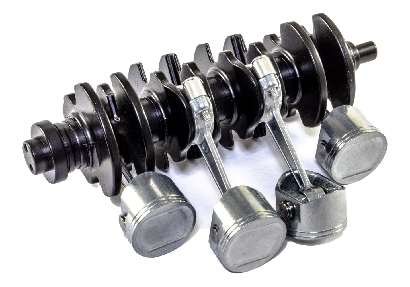
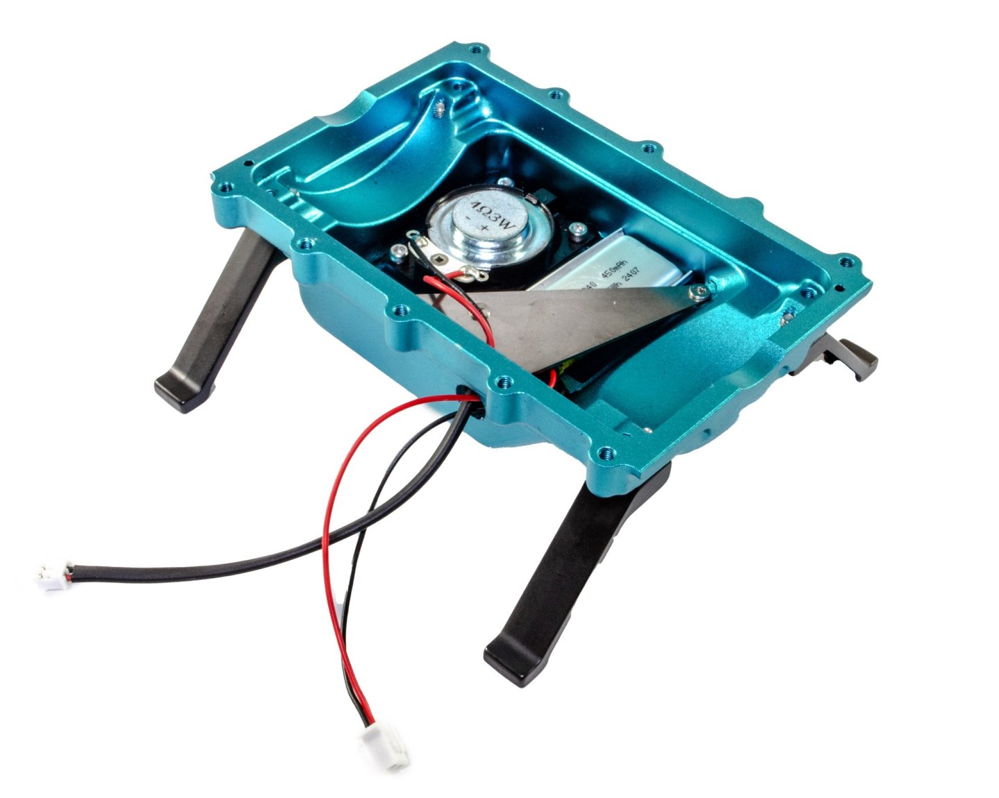
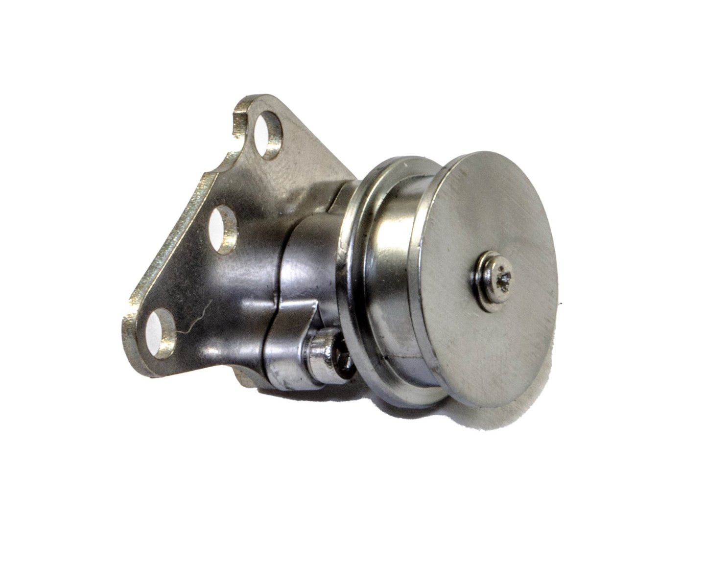
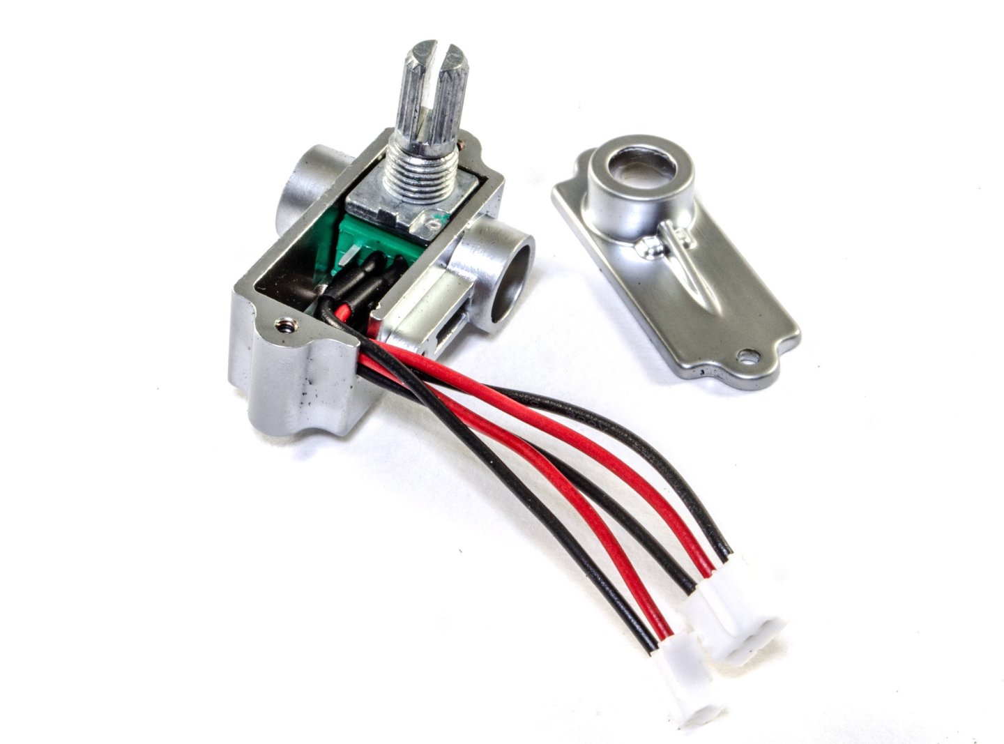
The build starts with building the four pistons. These are quite simple and consist of the pushrod and piston heads, held in place with a steel pin and two circlips. These are also lubricated with a little light oil before assembly. The pistons are then connected to the crankshaft. This assembly is now fitted to the crankcase. At this point, I hadn't noticed that I'd put the crankshaft in the wrong way around, so you'll see it like this for a few shots. In fairness to me, the images in this manual do look a little muddy in places, and I there are some errors too with images being mirrored or numbered incorrectly. Having said that, the model is generally easy to build as the parts look quite distinct. Here you also see the sump, with the display feet fitted. Unlike the V8 I built, this model has sound, with the speaker in the sump. This is also where the battery hides out. The exhaust system is now built up out of multiple parts that need to orientate correctly. The electric motor is then fitted into its forward housing, along with its gear and fence. Once complete, the rear shell is then fitted, enclosing the electric motor. It's now the turn of the water pump to be built. While this does have bearings and rotates, it's only representative here and will not be used to pump water! A belt pulley is now built up, using more bearings. This engine pulley is a little more complex, but is so engineered that it rotates very smoothly, and will of course be used to assist in the operation of this engine. The air filter is merely decorative, but as this engine has one, it needs to be fitted. And this little unit contains a potentiometer. When installed, this will have the effect of increasing and decreasing the engine's revs, and therefore its speed. This needs to be set up in a specific way so that it operates from a neutral position. The crankcase can now be bolted to the sump. It's here that you will need that modified hex key. ......more soon.


-
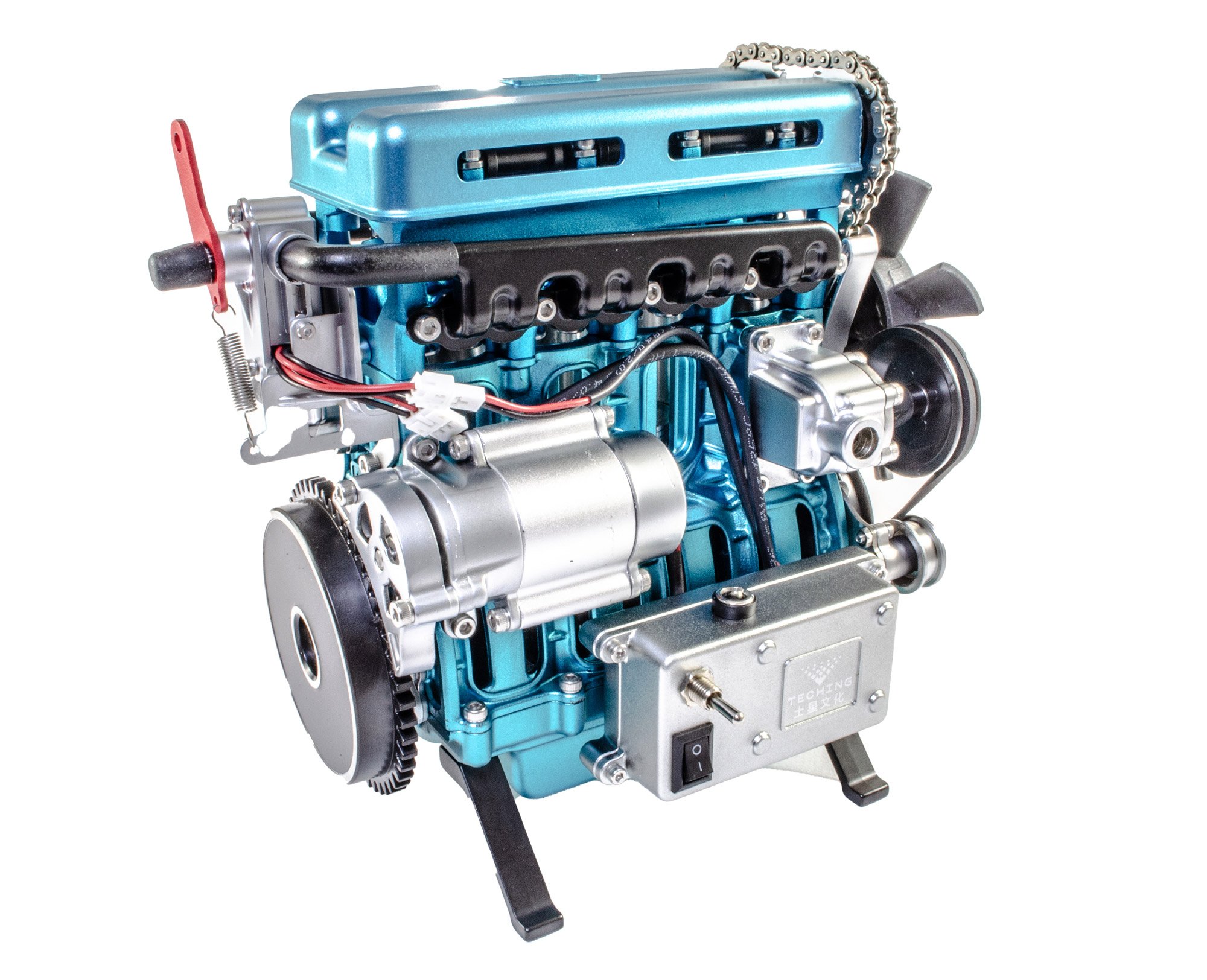
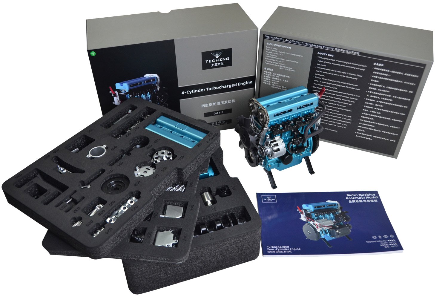
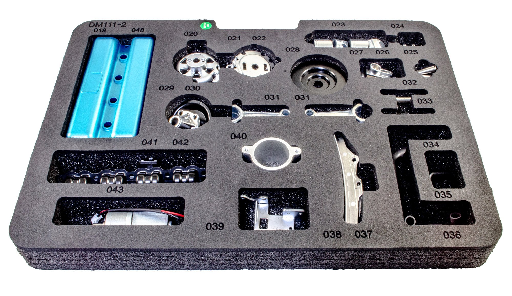
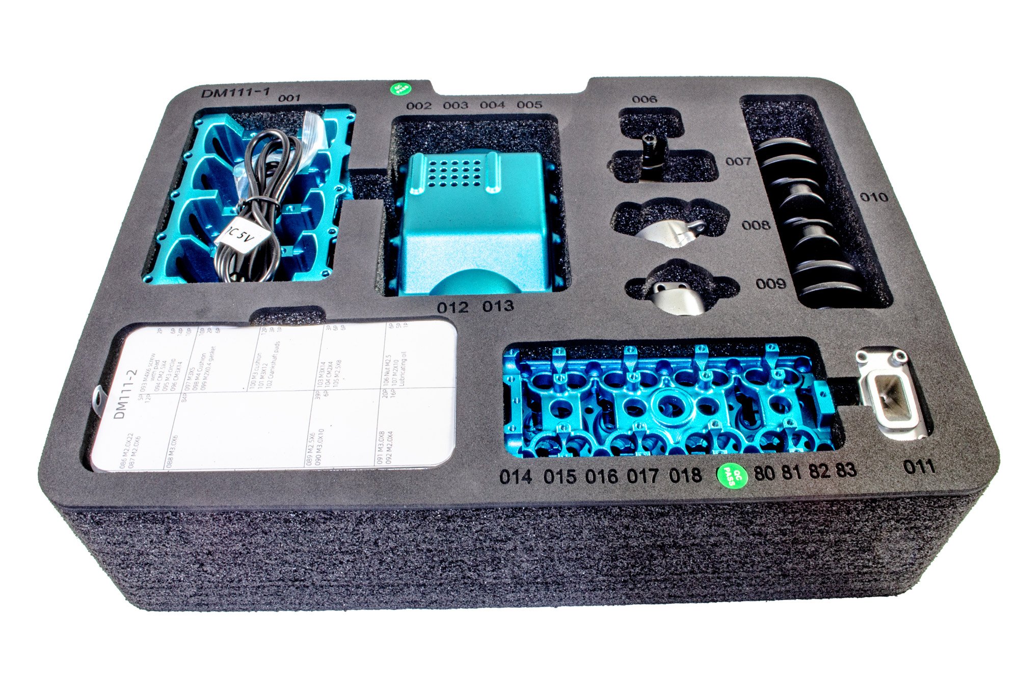
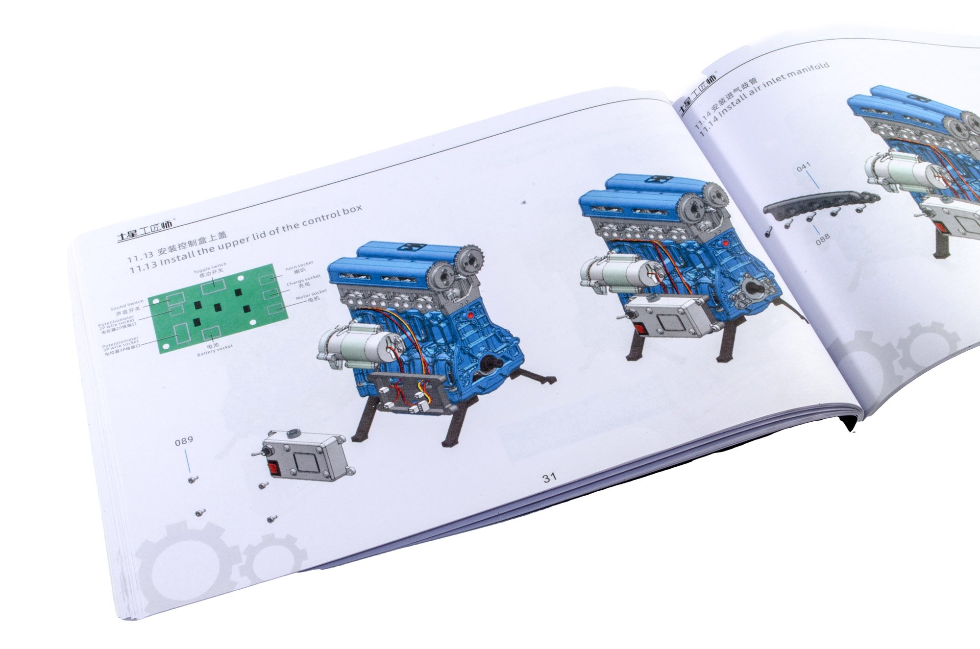
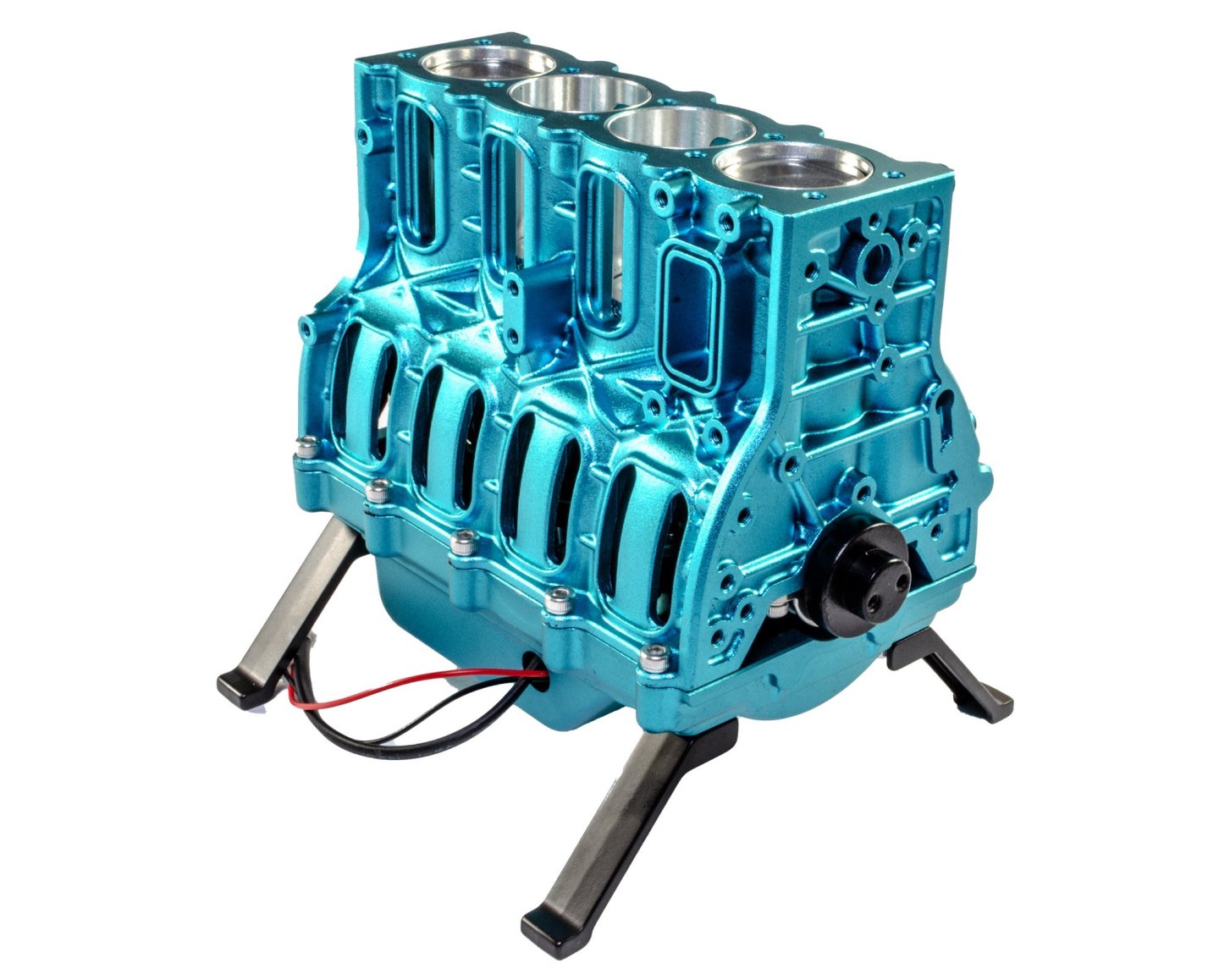
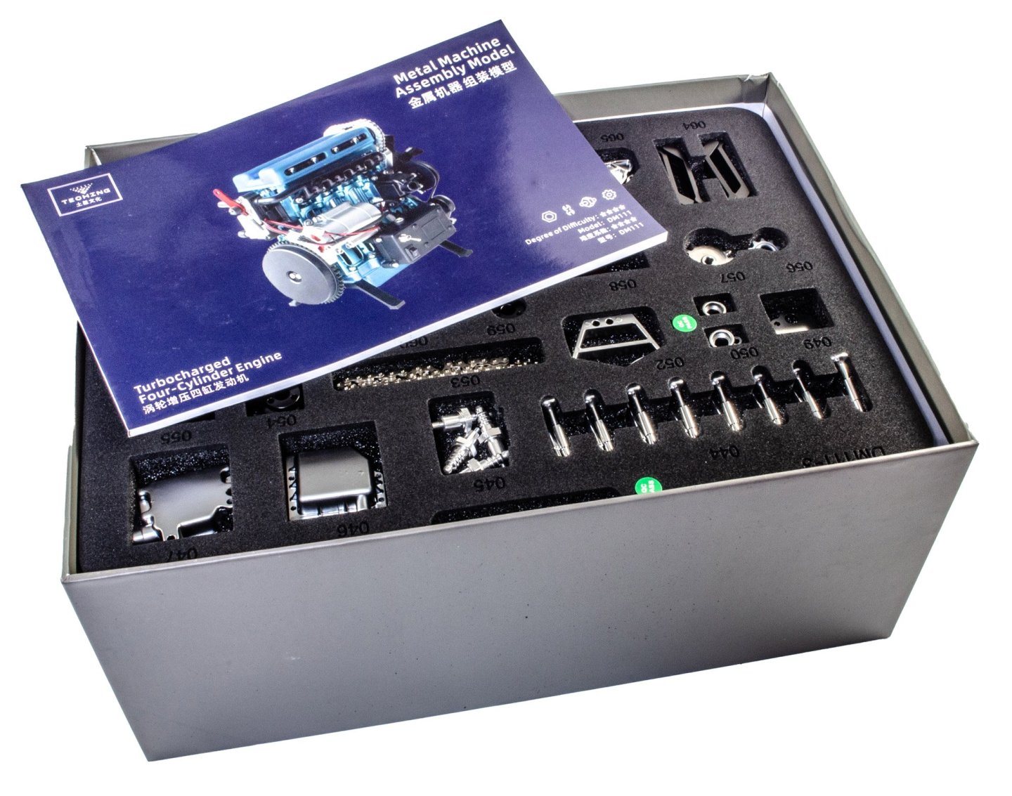
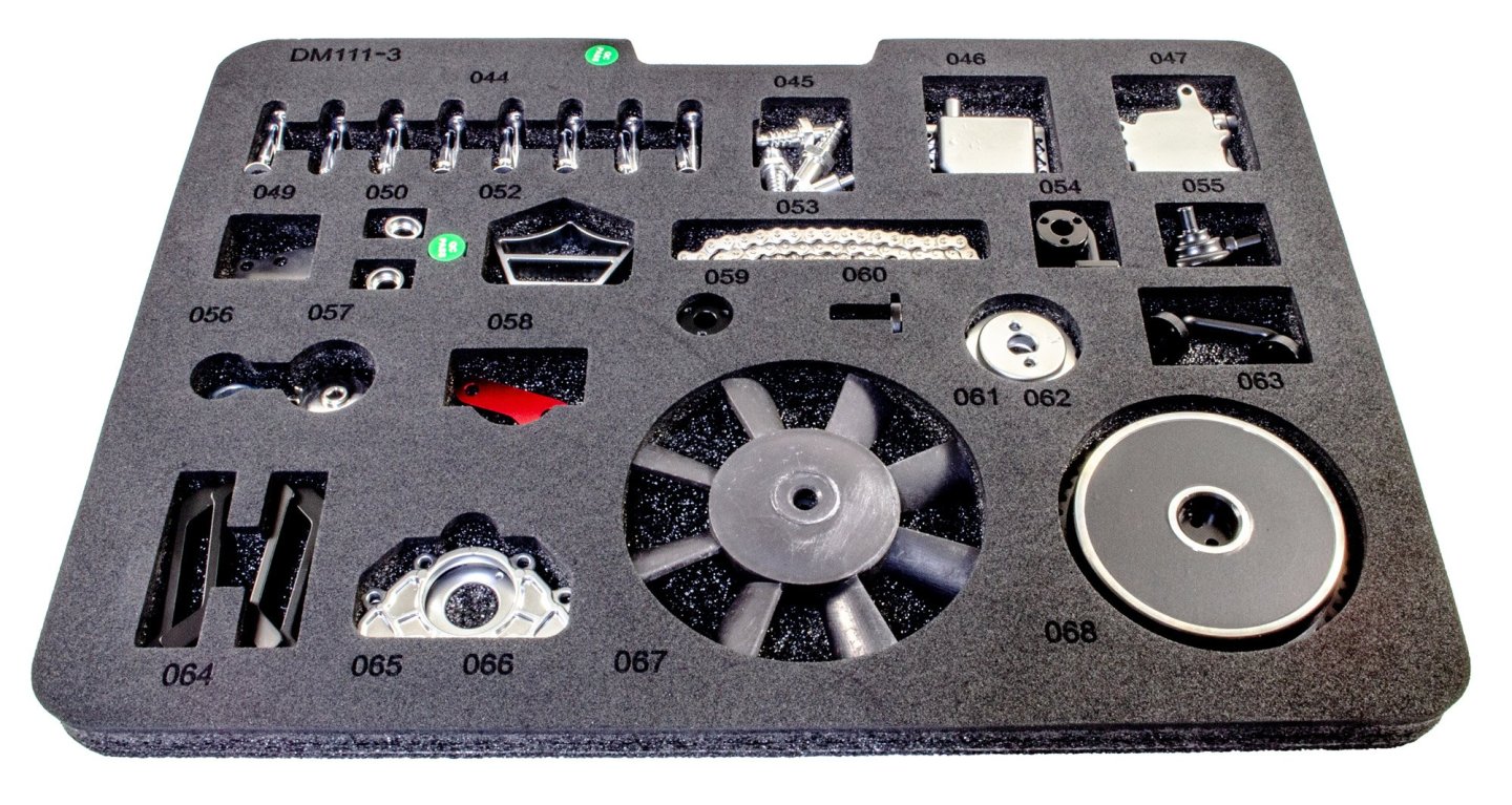
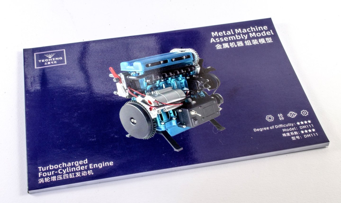
L4 Engine - Teching - vie EngineDIY (Build Review) Available from EngineDIY for $499.99 An L4 (straight-four engine, also referred to as an inline-four engine) is a four-cylinder piston engine where cylinders are arranged in a line along a common crankshaft. The majority of automotive four-cylinder engines use a straight-four layout, with the exceptions of the flat-four engines produced by Subaru and Porsche. Here, the layout is also very common in motorcycles and other machinery. Therefore the term "four-cylinder engine" is usually synonymous with straight-four engines. When a straight-four engine is installed at an inclined angle (instead of with the cylinders oriented vertically), it is sometimes called a slant-four. A four-stroke straight-four engine always has a cylinder on its power stroke, unlike engines with fewer cylinders where there is no power stroke occurring at certain times. Compared with a V4 engine or a flat-four engine, a straight-four engine only has one cylinder head, which reduces complexity and production cost. Abridged from Wikipedia. The kit This is another heavy kit, this time packed into an almost bomb-proof high density card box that even Apple would be proud of. The lid comes off real slow to allow for the air to get in there! The packaging is very attractive, with all panels adorned with photos and data. EngineDIY also say this of the kit: Product name: Inline four-cylinder engine model Material: aluminium alloy + stainless steel colour: blue Coloring process: anodizing Number of parts: 364+PCS Finished product size: 158.5*117*182mm Finished product weight: 1747g External power supply: DC 5V (USB cable charging) Lithium battery capacity: 500mAh Charging time: 2h Battery life: 30+min (when fully charged) Assembly time: 4h Skill level 4/5 There are THREE parts trays in this kit, with all parts being snugly held in a laser slot, with the part number engraved adjacent to the part. It's nigh on impossible not to be able to find a part quickly. It also needs to be known that all of the nuts, bolts, washers, and a number of other specific kit parts such as piston caps, springs, bearings, etc. are to be located in one of TWO compartmented tubs. These have part numbers on the lid of each compartment, making it a breeze to find what you need. Some tools are also included, but I decided to use my Wera tool set mostly. One bolt requires a modified (cut down) hex key, and this is included in the kit. A 72-page colour manual is included. This details the build in coloured illustration, along with text regarding the engine itself, and a complete parts chart. More very soon...


-
Kit review 1:25 Drakkar ‘Oseberg’ - Ships of Pavel Nikitin
James H replied to James H's topic in REVIEWS: Model kits
I hope you consider a build log for this? -
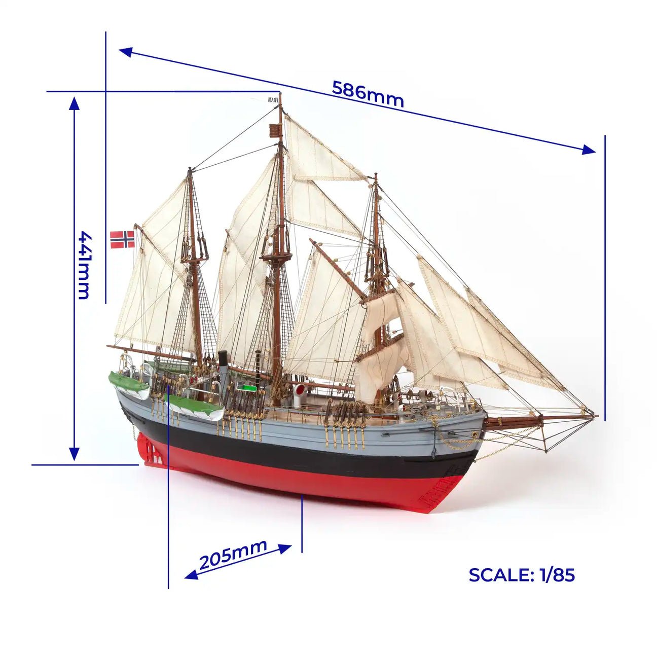
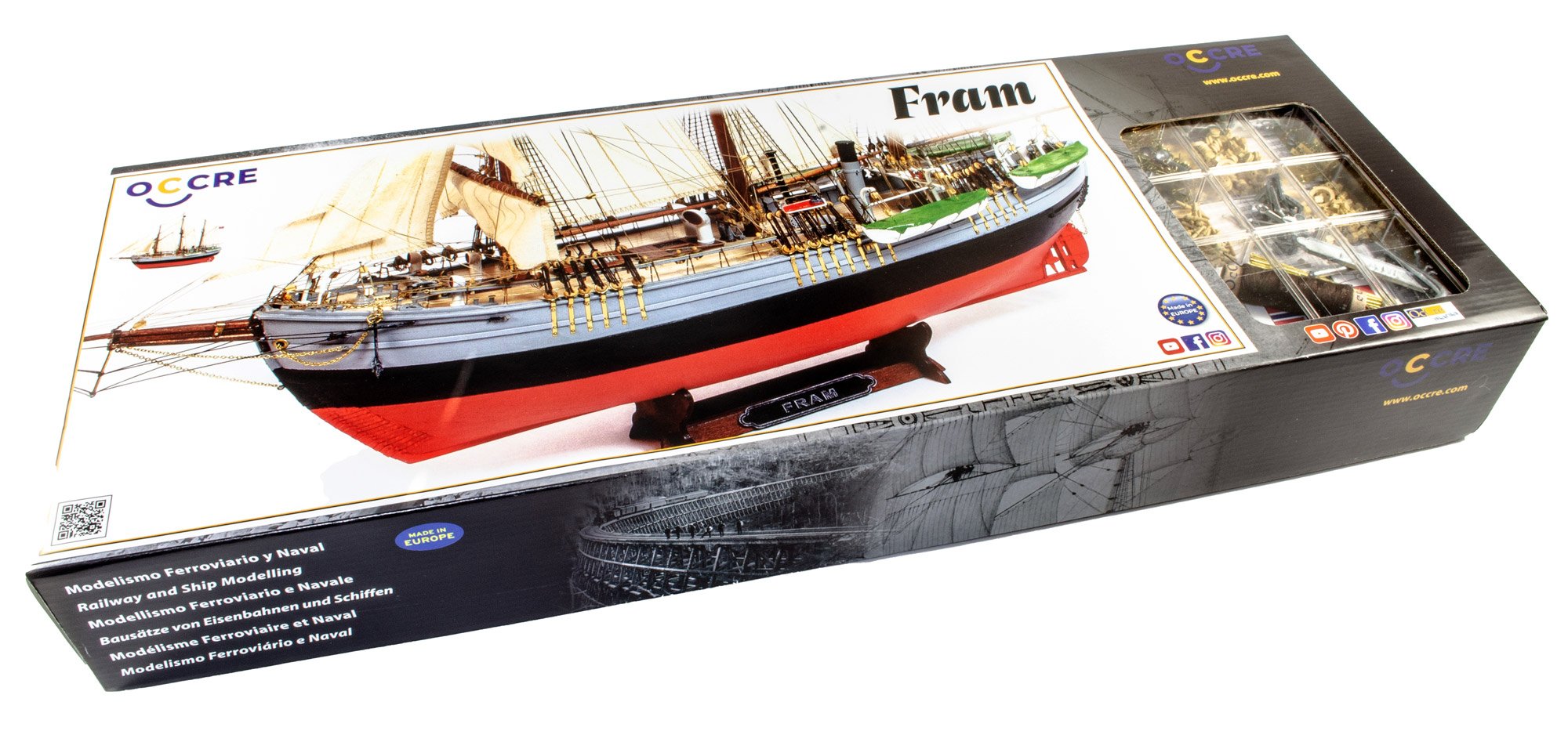
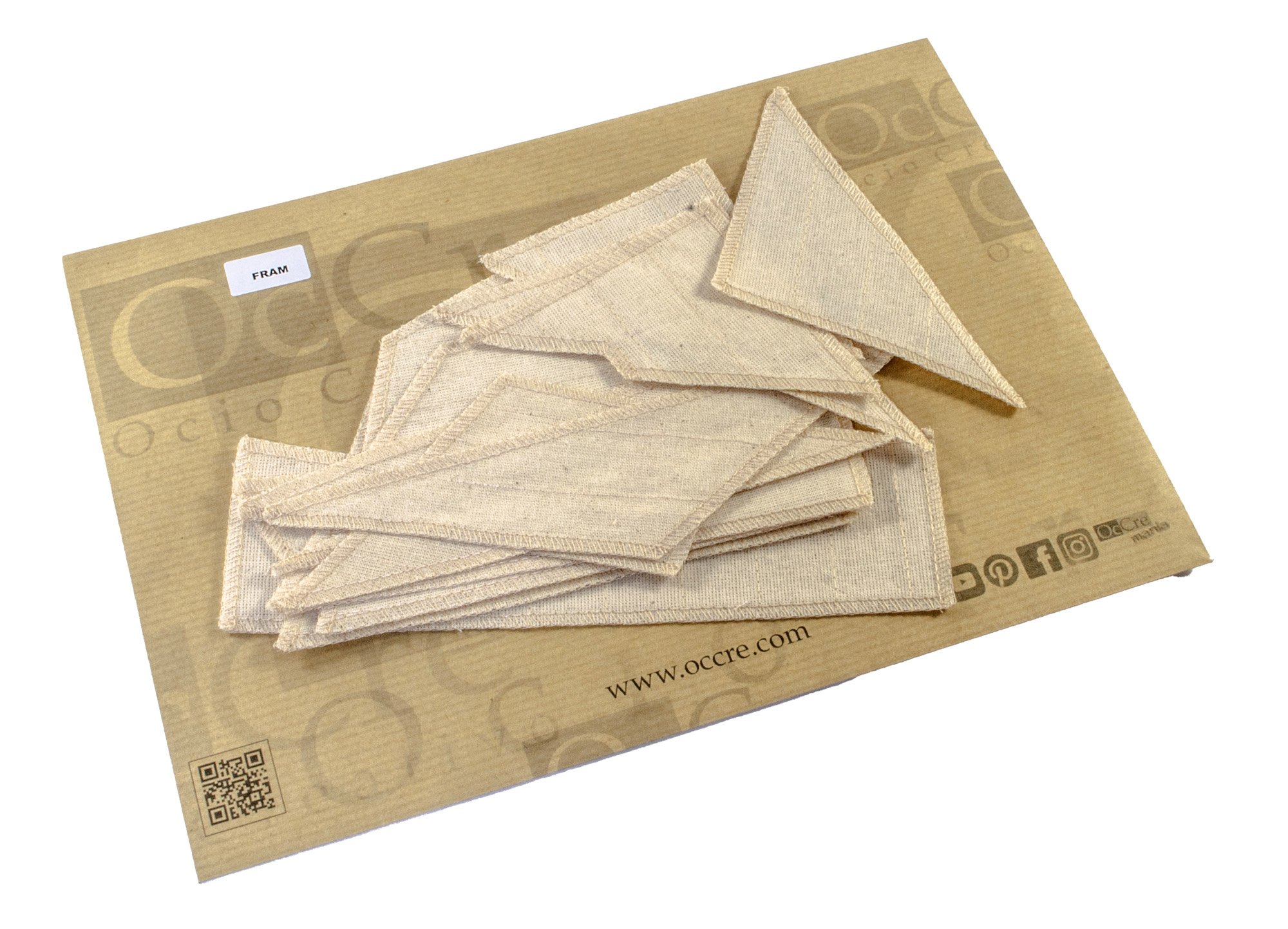
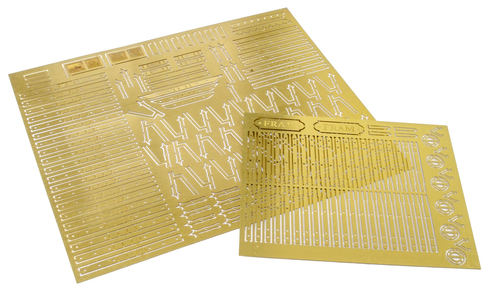
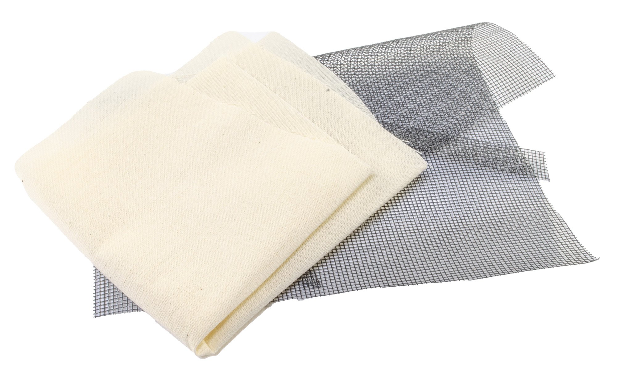
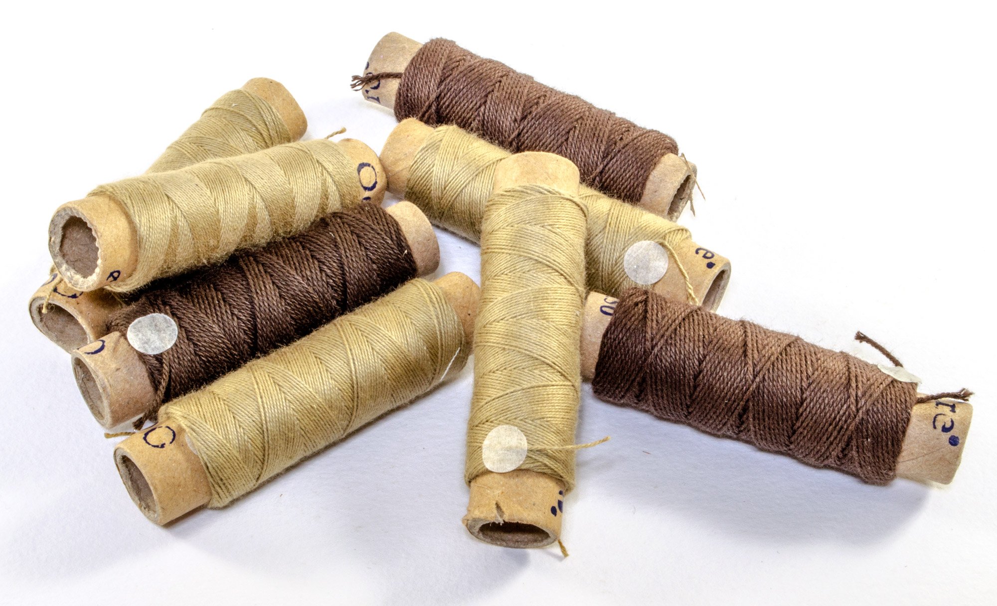
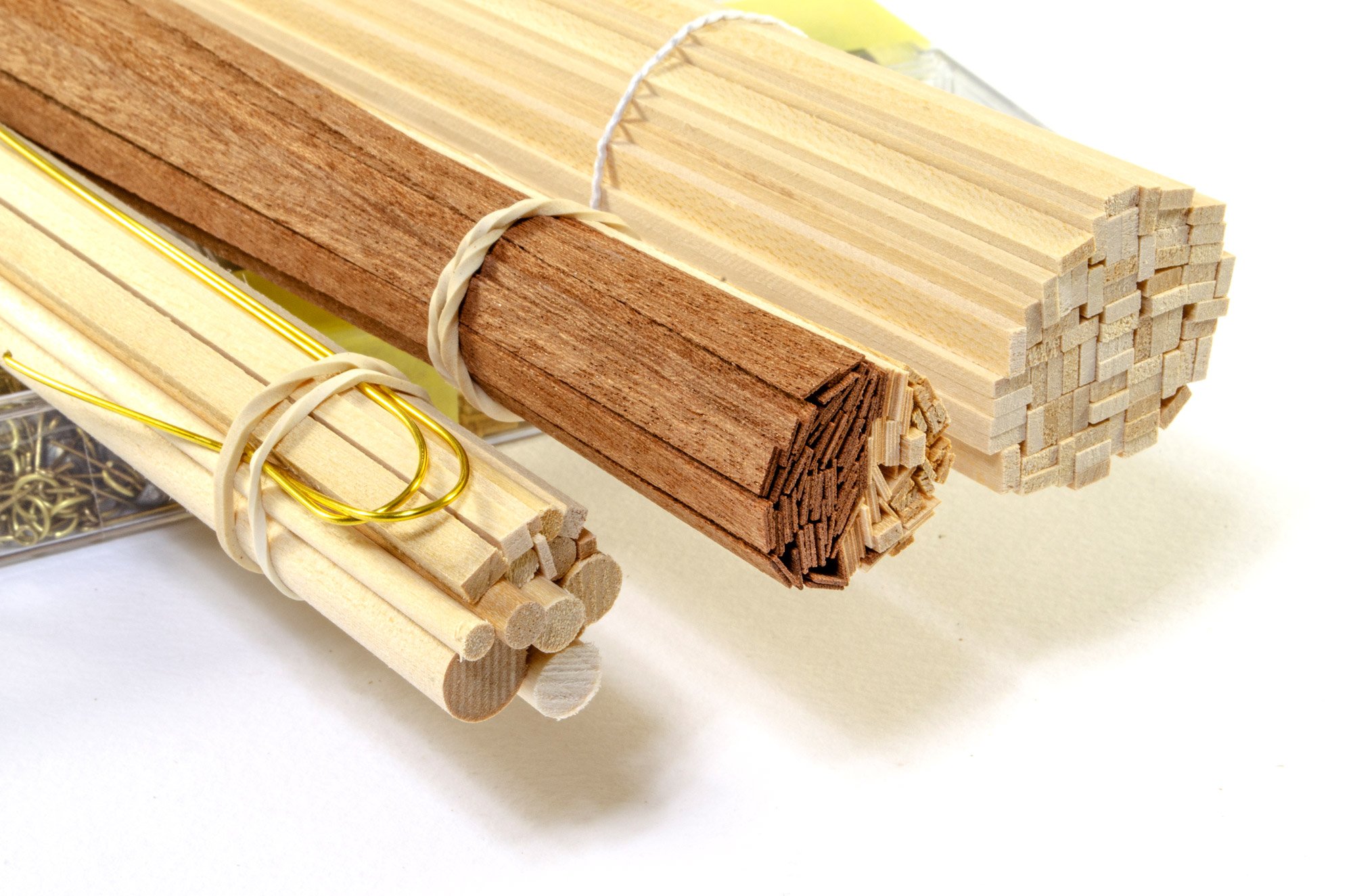
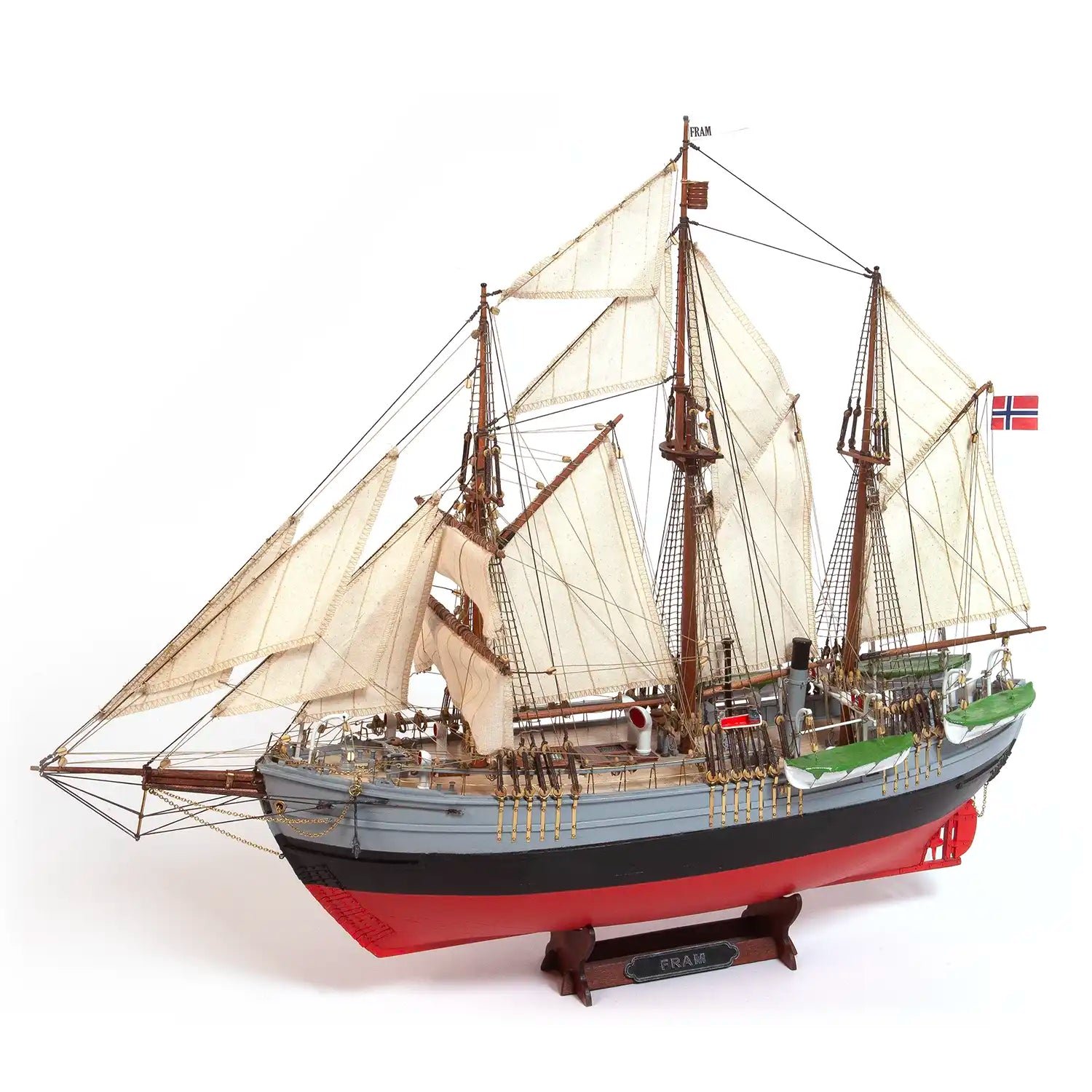
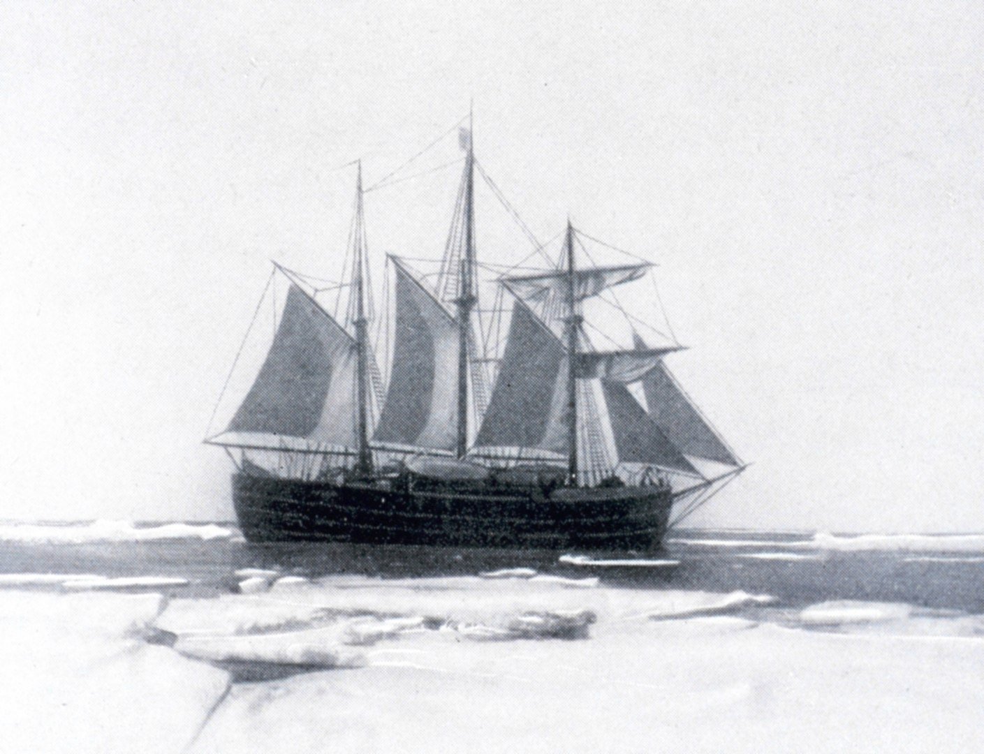
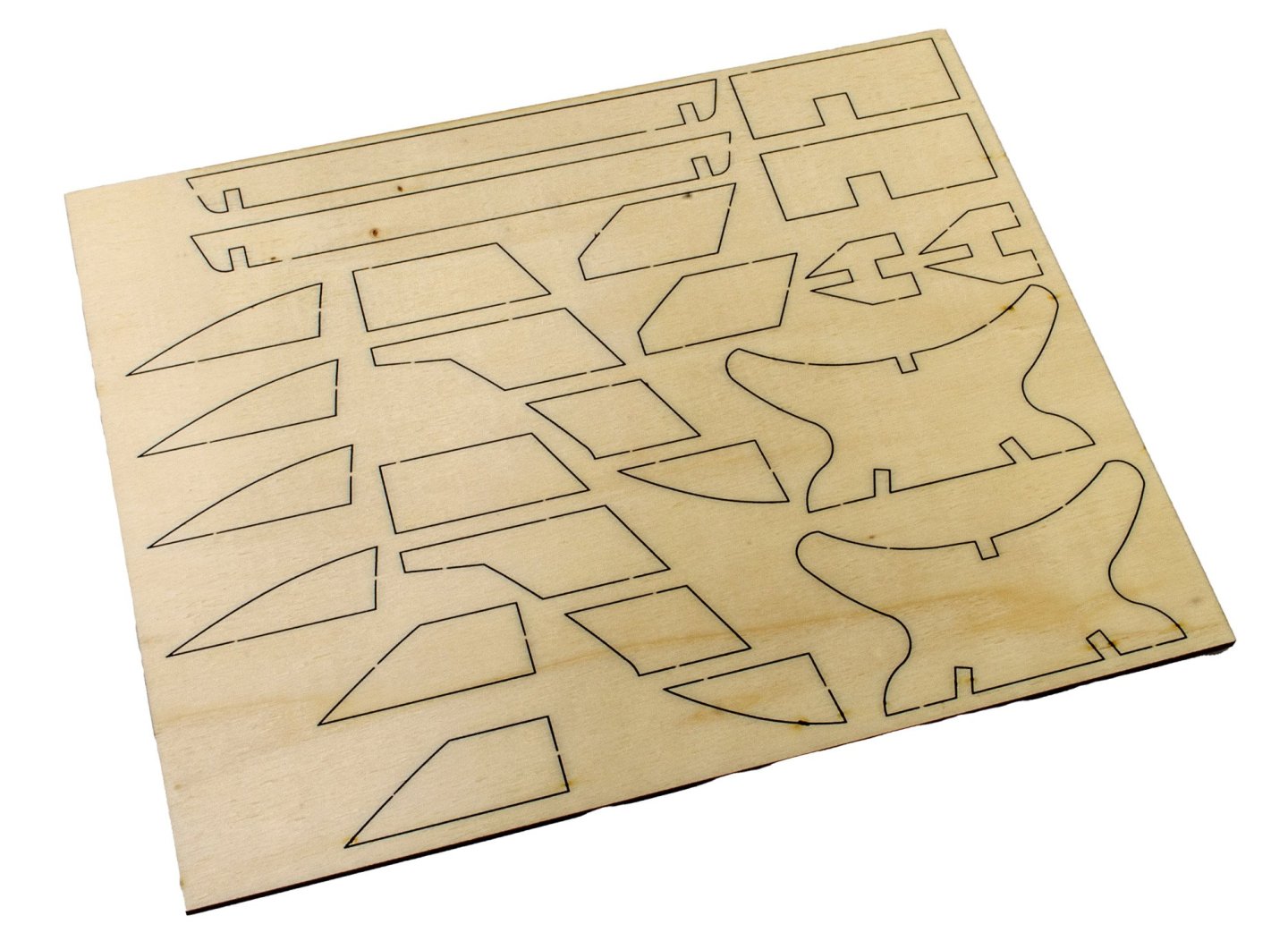
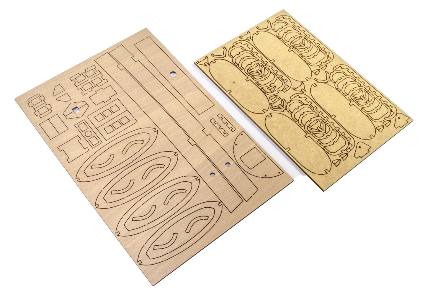
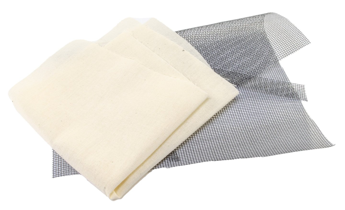
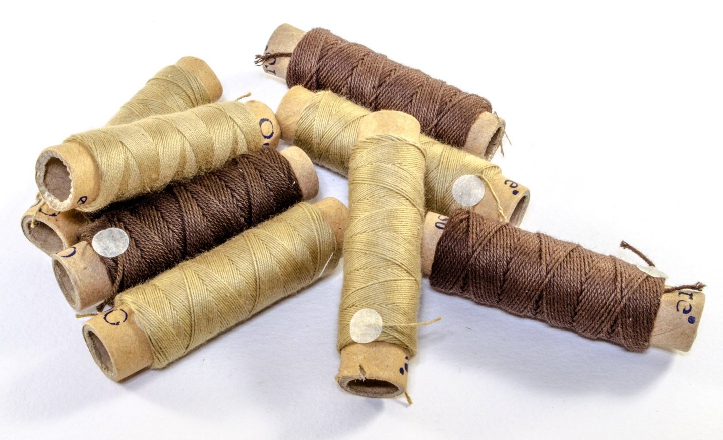
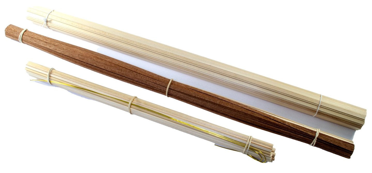
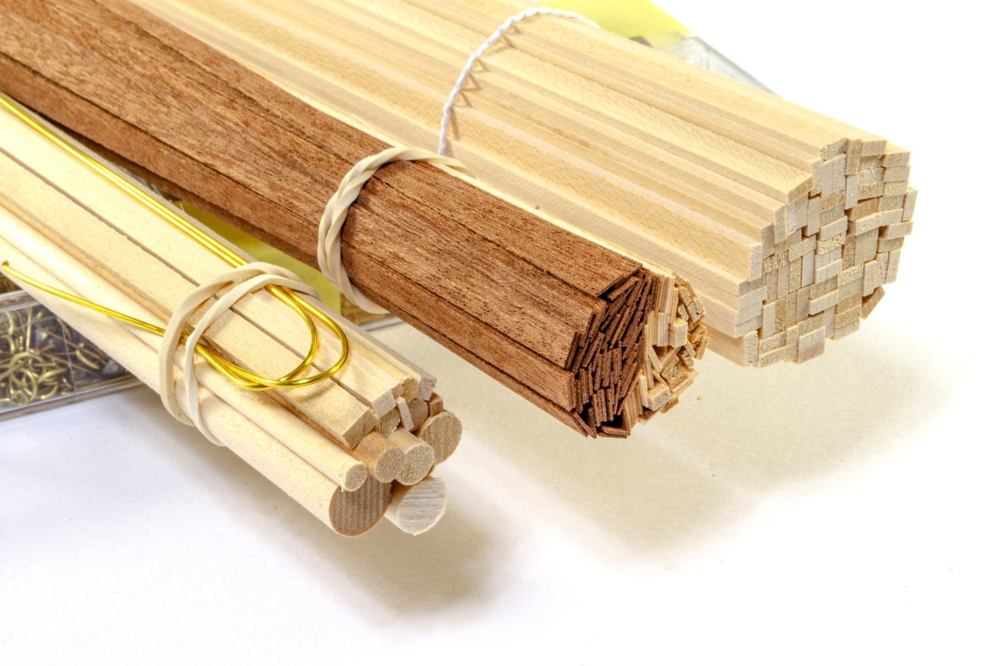
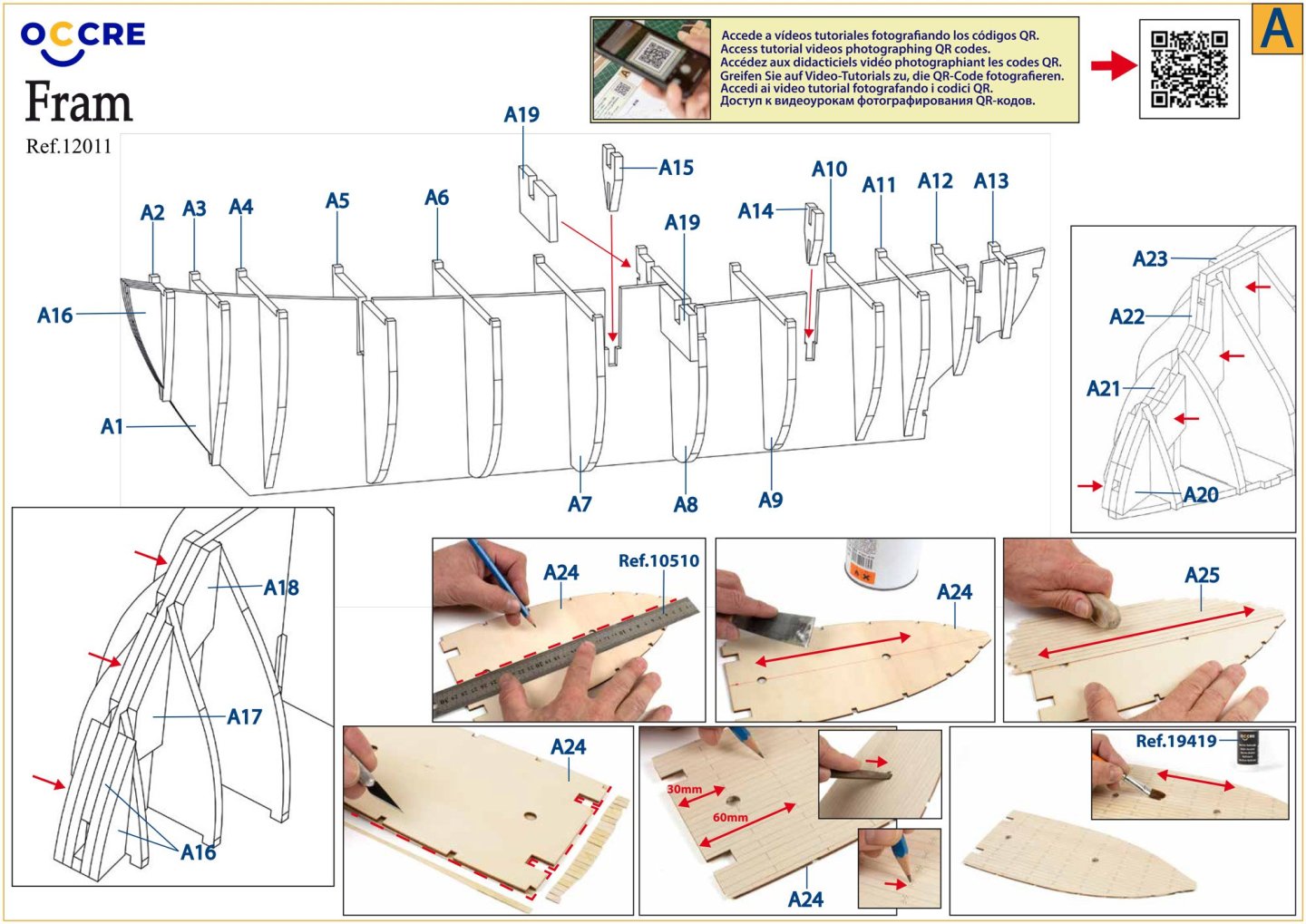
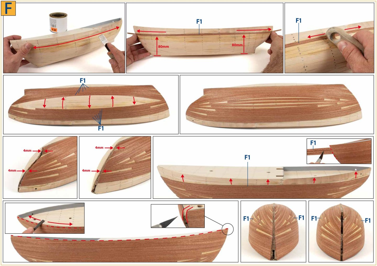
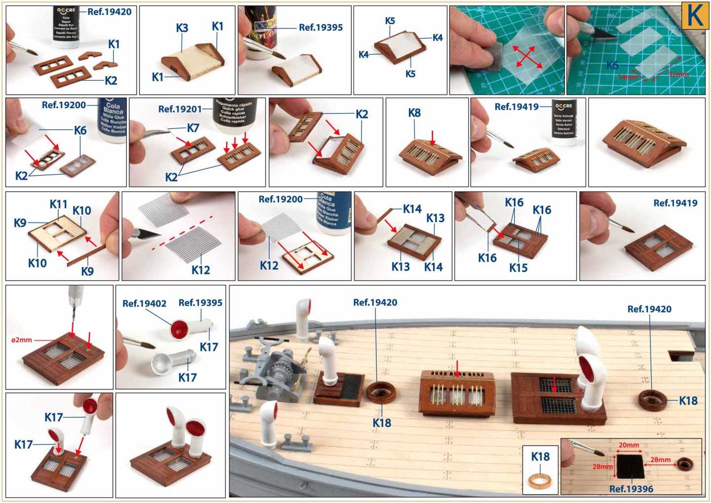
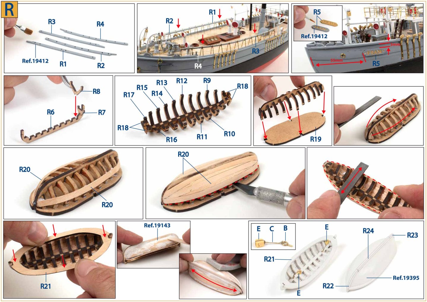
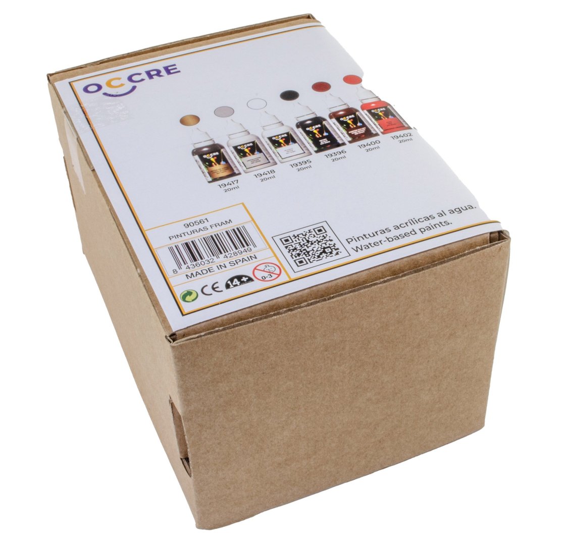
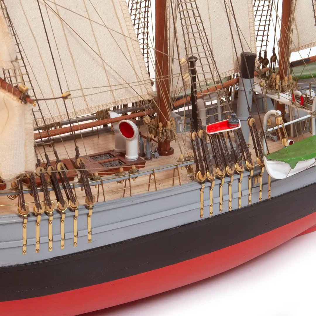
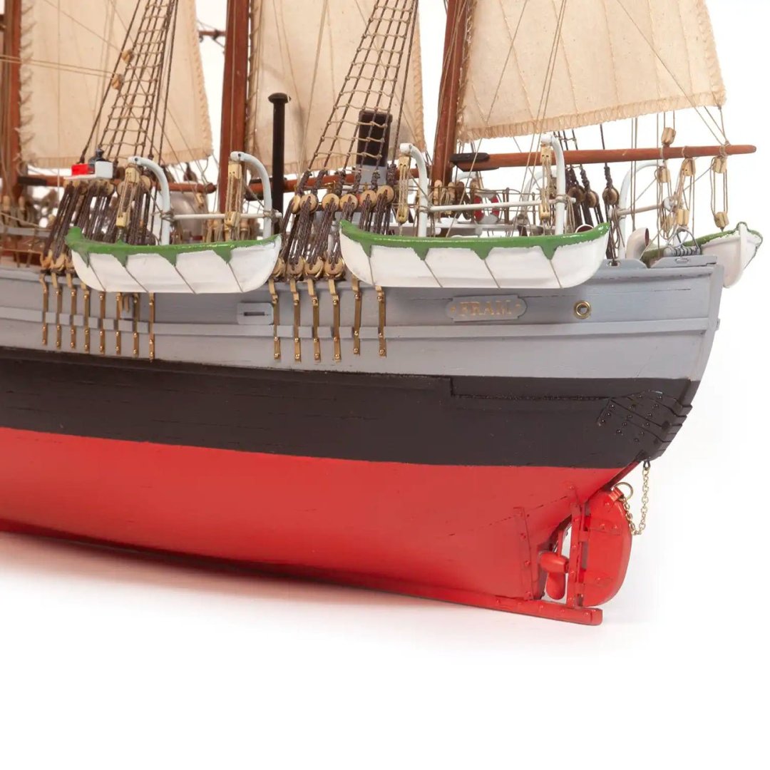
1:85 Fram OcCre Catalogue # 12011 Available from OcCre for €199,99 Fram ("Forward") is a ship that was used in expeditions of the Arctic and Antarctic regions by the Norwegian explorers Fridtjof Nansen, Otto Sverdrup, Oscar Wisting, and Roald Amundsen between 1893 and 1912. It was designed and built by the Scottish-Norwegian shipwright Colin Archer for Fridtjof Nansen's 1893 Arctic expedition in which the plan was to freeze Fram into the Arctic ice sheet and float with it over the North Pole. Today, the historic ship resides at the Fram Museum in Oslo. It is one of the most visited and renowned museums in the city. This prestigious museum is a must-see for travellers interested in polar exploration and maritime history, as it provides a unique experience combining detailed information, immersive exhibits, and the chance to closely admire the resilient vessel that once braved the Arctic and Antarctic ice fields. The Fram Museum has become a world-renowned landmark, reflecting the legacy of adventurers like Fridtjof Nansen and Roald Amundsen, whose feats helped broaden our understanding of the most remote regions of the planet. Abridged from Wiki and OcCre The kit Fram is packaged into OcCre’s medium size generic box that has an opening to see the parts tray, plus a product label secured to the top of the lid. The package is quite sturdy, which I always good for shipping. With the lid off the off, the box contents are accessed by pushing open the sides and then opening the formed card flaps which hold the various parts in place to stop them rattling about. There seems a modest number of timber parts in this, relatively speaking, but the model itself when complete builds up as below, with this image showing the size of the finished vessel. All timber materials are supplied in a shrink wrapped cellophane sheet, protecting them and stopping them rattling around in the box. Fram is constructed in the standard plywood POB style. A dozen bulkheads are laser cut into a single piece of ply. Note that there's no part numbers engraved. These are shown on the plans, so it's a good idea to write the ID on each of these key parts. The main deck is split into two to represent the split level nature of the ship. Other parts you see here are for the lower deck access door housings, poop deck stairways, etc. On this ply sheet you will find the cradle for building and displaying Fram. This will need a good priming/sealing and paint/stain to make it suitable for actual display purposes. Bow and stern filler parts are included on this sheet. Fram's false keel is supplied in a single piece on this sheet. We are now onto actual timber sheets, and here you will find keel parts and various gunwale sections. Whilst there are some deck fitting elements on this timber sheet, the rest of the parts sheet, and the accompanying ply sheet are concerned with the building of the four ship's boats, which are identical. These are constructed in very much the same way as others that you may have seen me build on my prototype work. This involves creating a framework over a base. The frames are then planked before the base is removed, leaving you with a little boat. Three bundles of strip wood are supplied, along with brass wire. The first hull planking layer is lime, followed by the darker, second layer of sapele. The wood is nicely cut and is of consistent quality throughout. All bundles are supplied with elastic ties to keep them together. If you like adding sails to your models, then there is a full suite of thirteen here, all pre-stitched and ready to fit. The colour of these is cream/off-white, so could be fitted to the model without any extra colour treatments. All sails are supplied flat, packed into an OcCre envelope. Another envelope is supplied in the package. This includes TWO brass photo-etch sheets, plastic mesh sheet for deck fittings, fabric sheet for boat tarpaulins, and eight spools of rigging cord in both dark and natural. There is a single fitting box with this kit, chock full of components in both bras and cast, along with rigging blocks, brass pins, brass wire, and more rigging cord. A printed Norwegian flag is also included. All rigging blocks and other machined wooden parts, such as barrels, are also found in this component box. Fram is bundled with a set of paper instructions, totalling 44 sides of colour-printed sheets which show Fram being built in a series of photographs. Included in the sheets is a parts list, parts map, rigging drawings, and plans. If you like to watch build videos, then this is also covered by OcCre. Click THIS link to access the Fram videos on their YouTube channel. https://youtu.be/UmquIiY-UjE?si=g4mQPVGyqvv-eTJp Conclusion OcCre have certainly been surprising the modelling community with their recent releases, and this was one that we didn't see coming until it was almost upon us. From a builder's perspective, I would say this was aimed at the advanced beginner/intermediate modeller, and to that end, this should serve its purpose perfectly, with plenty of detail throughout, including all of those sails, should you wish to add them. My sincere thanks to OcCre for sending out this kit for review/build on MSW. To purchase directly, click the link at the top of this article. WAIT!!!! That's not quite it. We have also been sent the paint set for this kit. This can be bought from OcCre for €29,99 via THIS link. This set contains the following: Sapele wood dye Satin varnish Grey Light green Red Dark brown Black White Judea bitumen Primer Paints and primer are supposed to be 20ml, although my grey and white bottles are larger in size. The varnish and dye are 50ml. These also appear to be acrylic, and I'm not sure whether any of these can be passed through an airbrush. You would need to dilute, possibly with distilled water, and test them first. For now, here are some completed images of Fram...


-
Unfortunately, that is the case. There are very few settings in the Gallery app, and it would need either a 3rd party plugin (not available) or a code customisation. We would also like to set it so members HAVE to create an album to add their images to, but that option isn't available either.