James H
-
Posts
5,961 -
Joined
-
Last visited
Content Type
Profiles
Forums
Gallery
Events
Everything posted by James H
-
 Just a reminder that the video instructions for this are continually being uploaded to Artesania's YouTube playlist. They are currently at video #42. Check it out here: https://www.youtube.com/watch?v=Y6VAfr_M2jg&list=PLSWjc49gHdjlmgxz-loTM9MorsDryYgHO
 -
There's Sphinx too. https://vanguardmodels.co.uk/product/hms-sphinx-1775/
-
There you go: https://vanguardmodels.co.uk/product/hms-indefatigable-1794/ There's a build log in my signature, and other build logs here on MSW.
-
I'm not generally a fan of video. I used some in the engine builds as that's the only way you can gauge the result. For static models, not so much.
-
Scrappee Liaison by chadwijm6 - Microaces - RADIO
James H replied to chadwijm6's topic in Non-ship/categorised builds
How did this go? -
Looking great, and that transition looks fine too.
-
I used that stuff all the time when I was building flying models. You needed good, er, ventilation.
-
On the prototype, this was done as with the other ships. The was sanded flush to the lime, then the second layer sits atop that.

-
Ok, this is now fixed. For some reason, the option to allow all file types, was set to 'none'. This isn't something that's been tinkered with, nor has there been any update, so it remains a mystery.

-
You have logged in to post that message.
-
Chaps, the password info is very good advice, but please can we keep this one on topic as it's extremely important.
-
Yes, sometime in the not to distant future. I can't say when as I don't know the date of the final release of V5. This topic is merely a heads up that it will happen, given with plenty of notice.
-
Not a problem. It did make me check though!
-
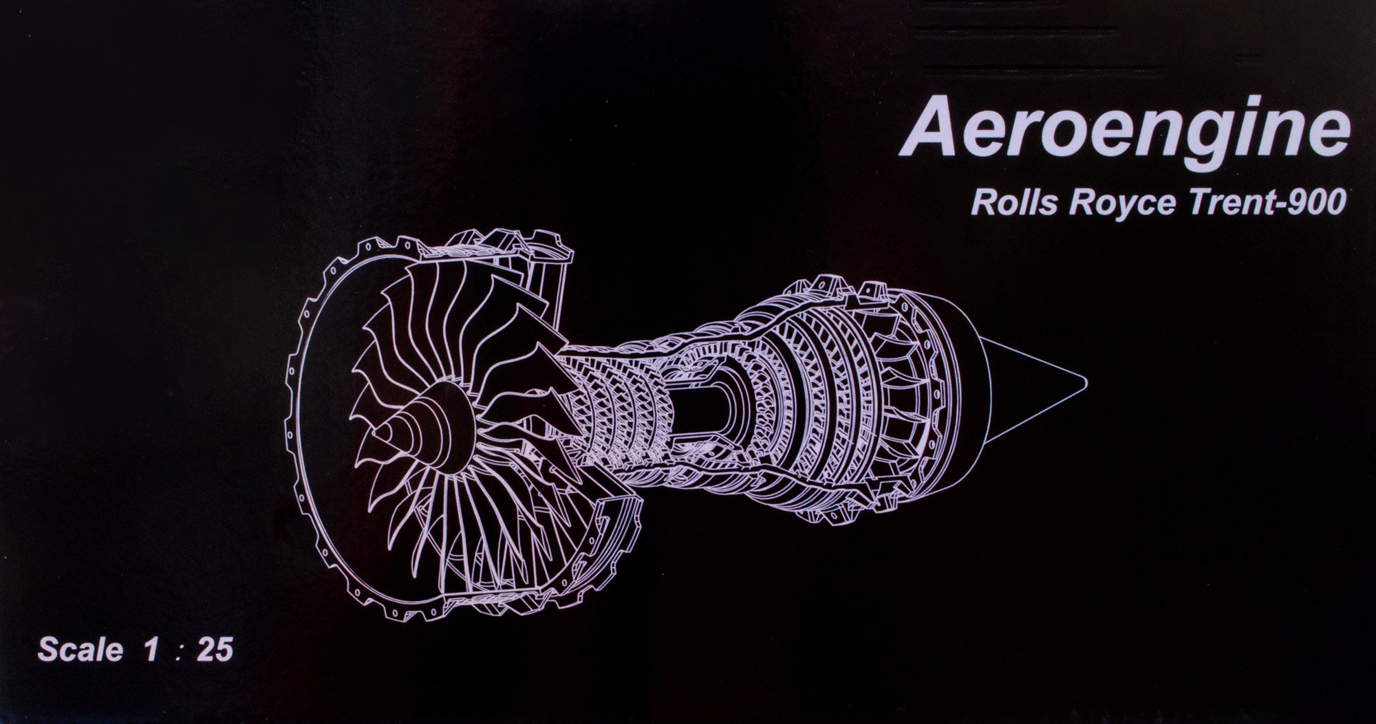
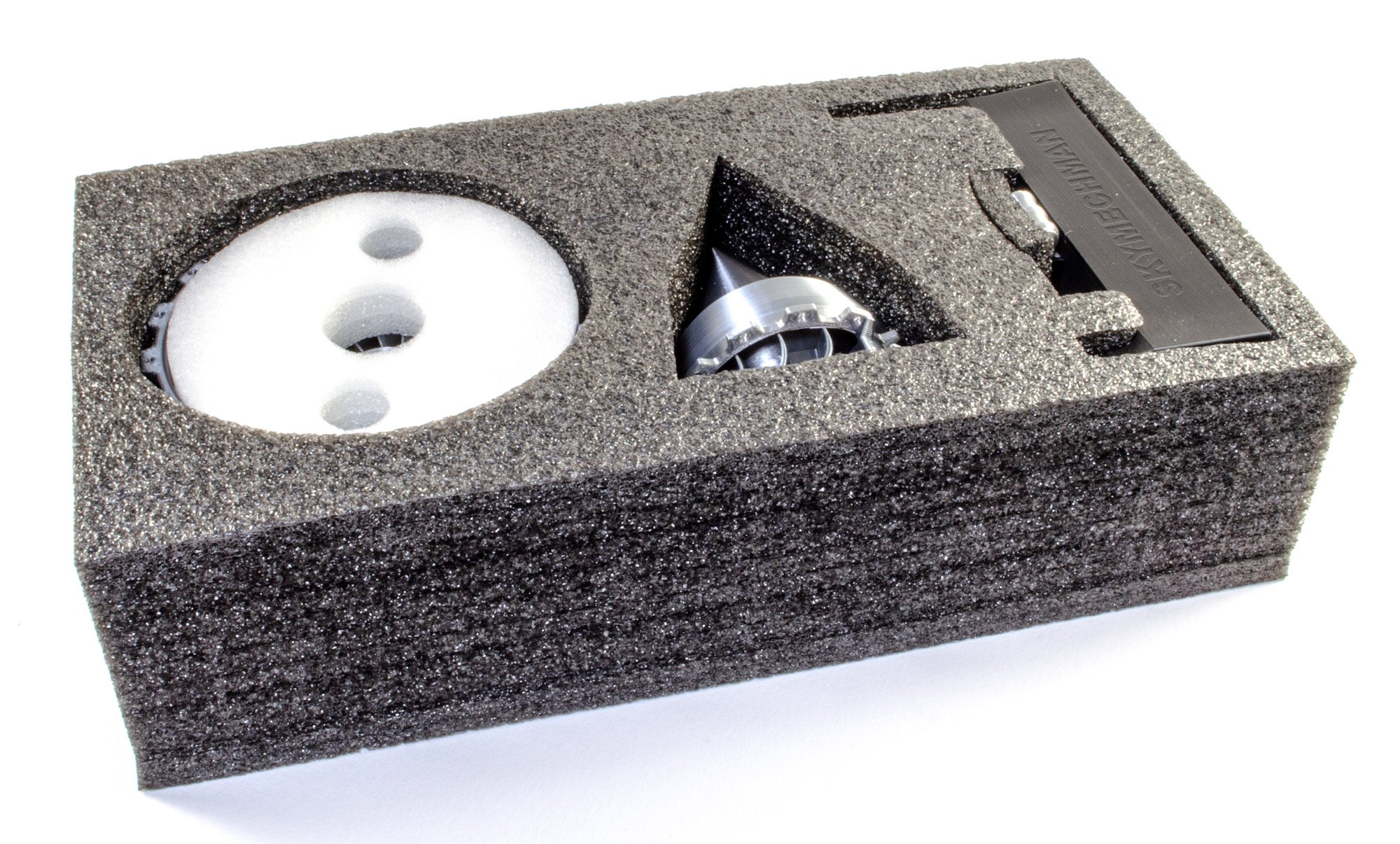
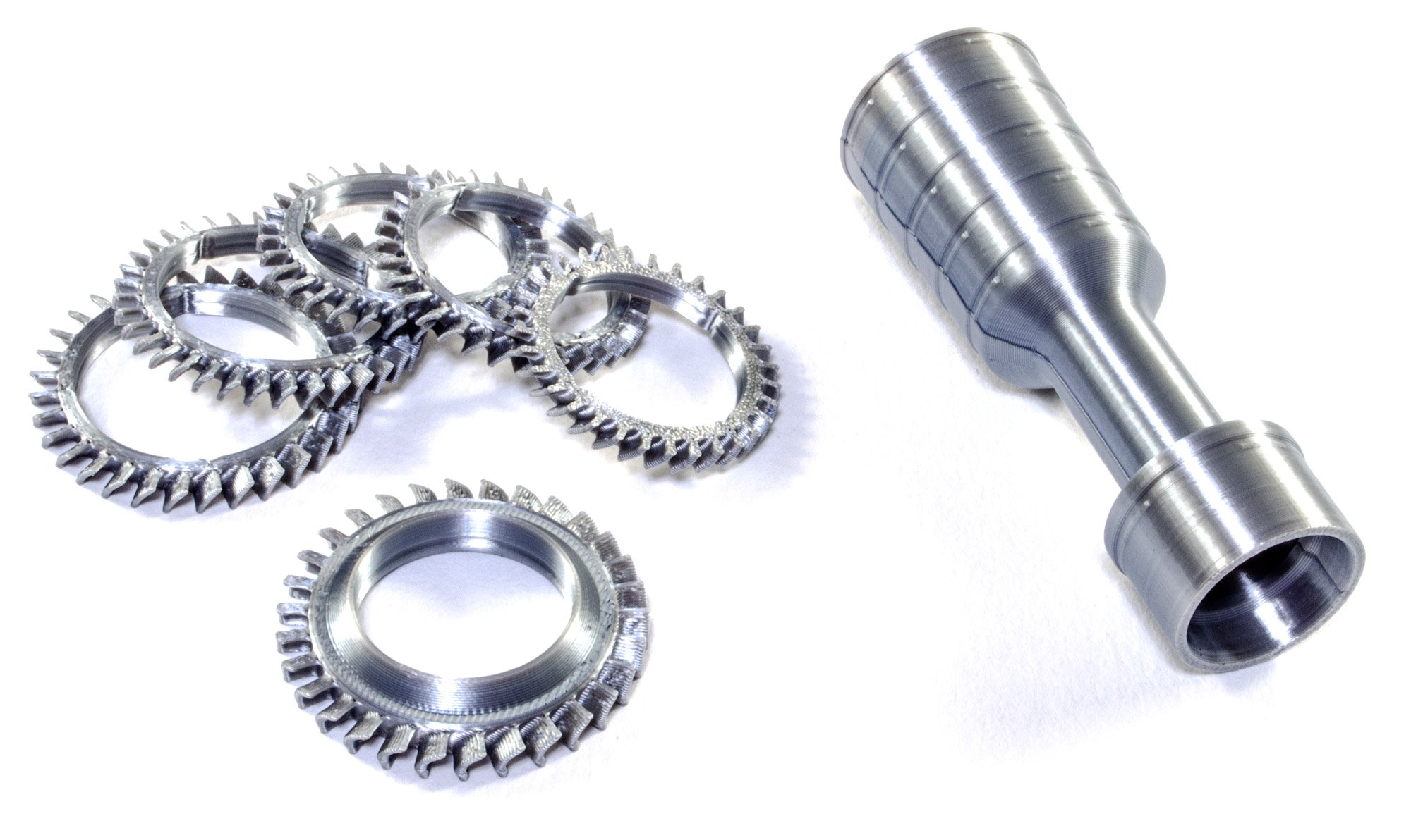
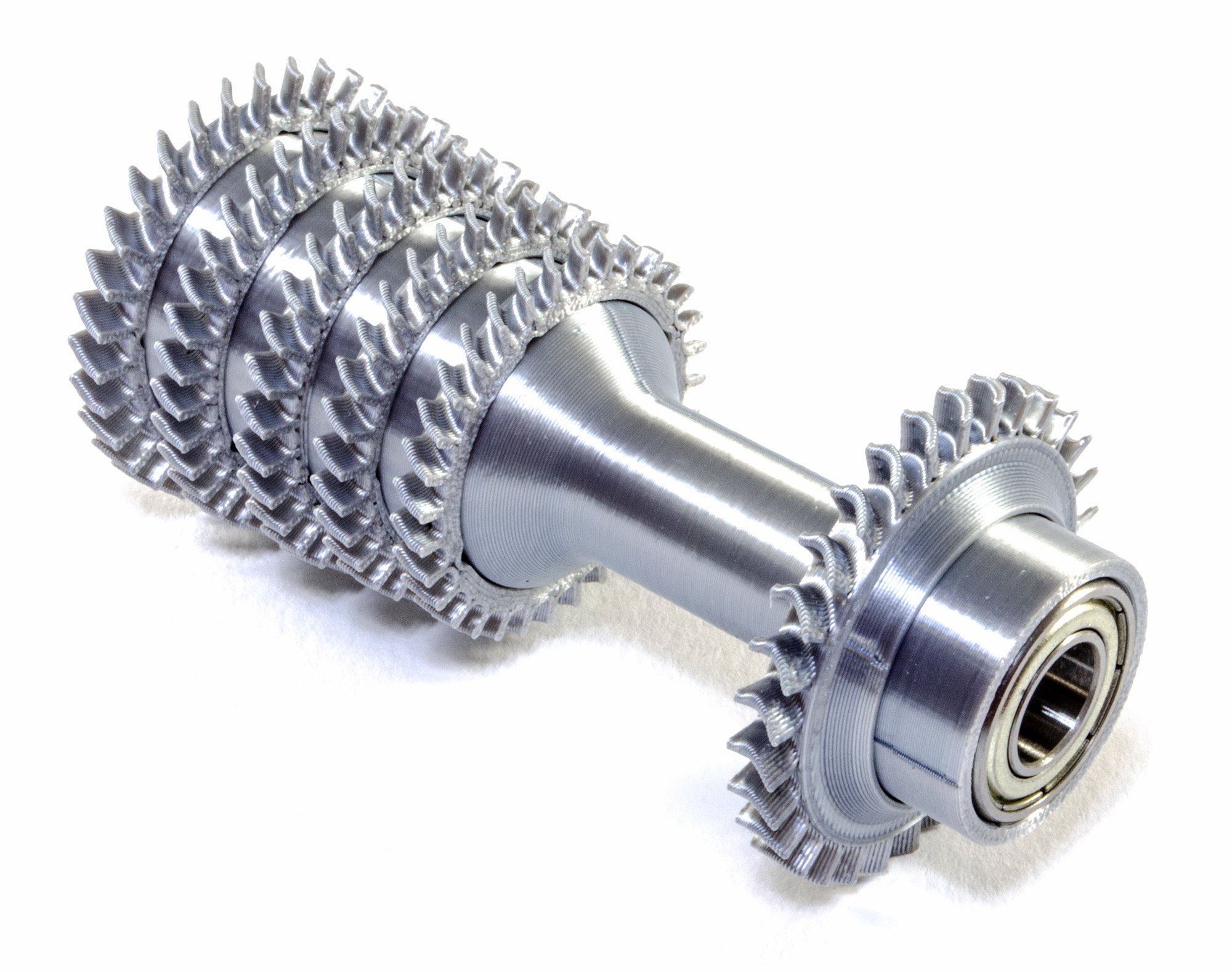
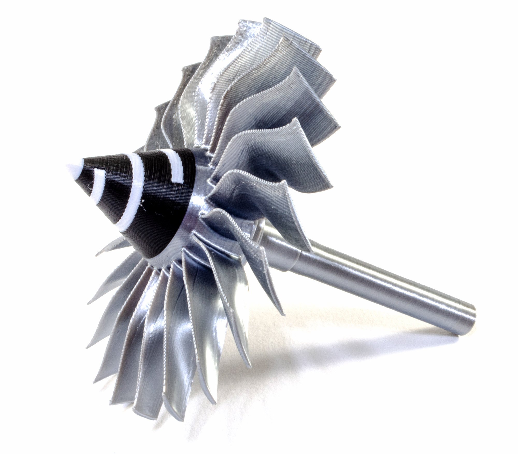
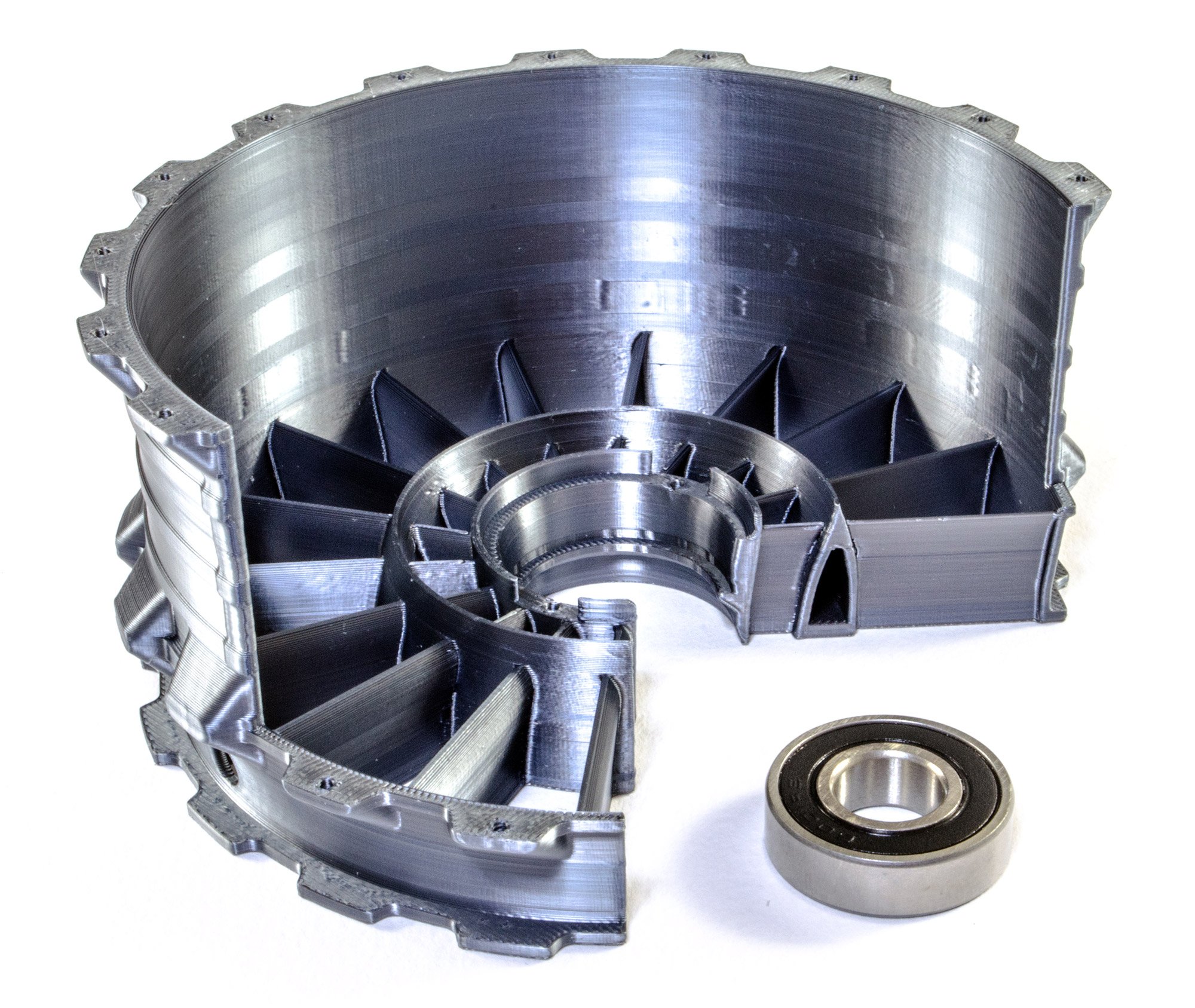
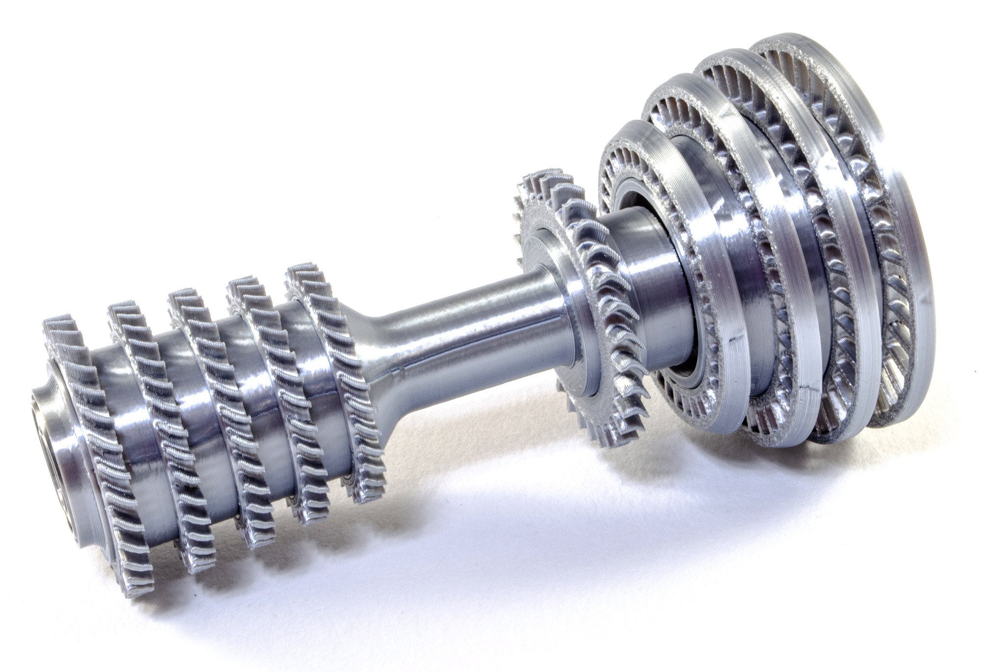
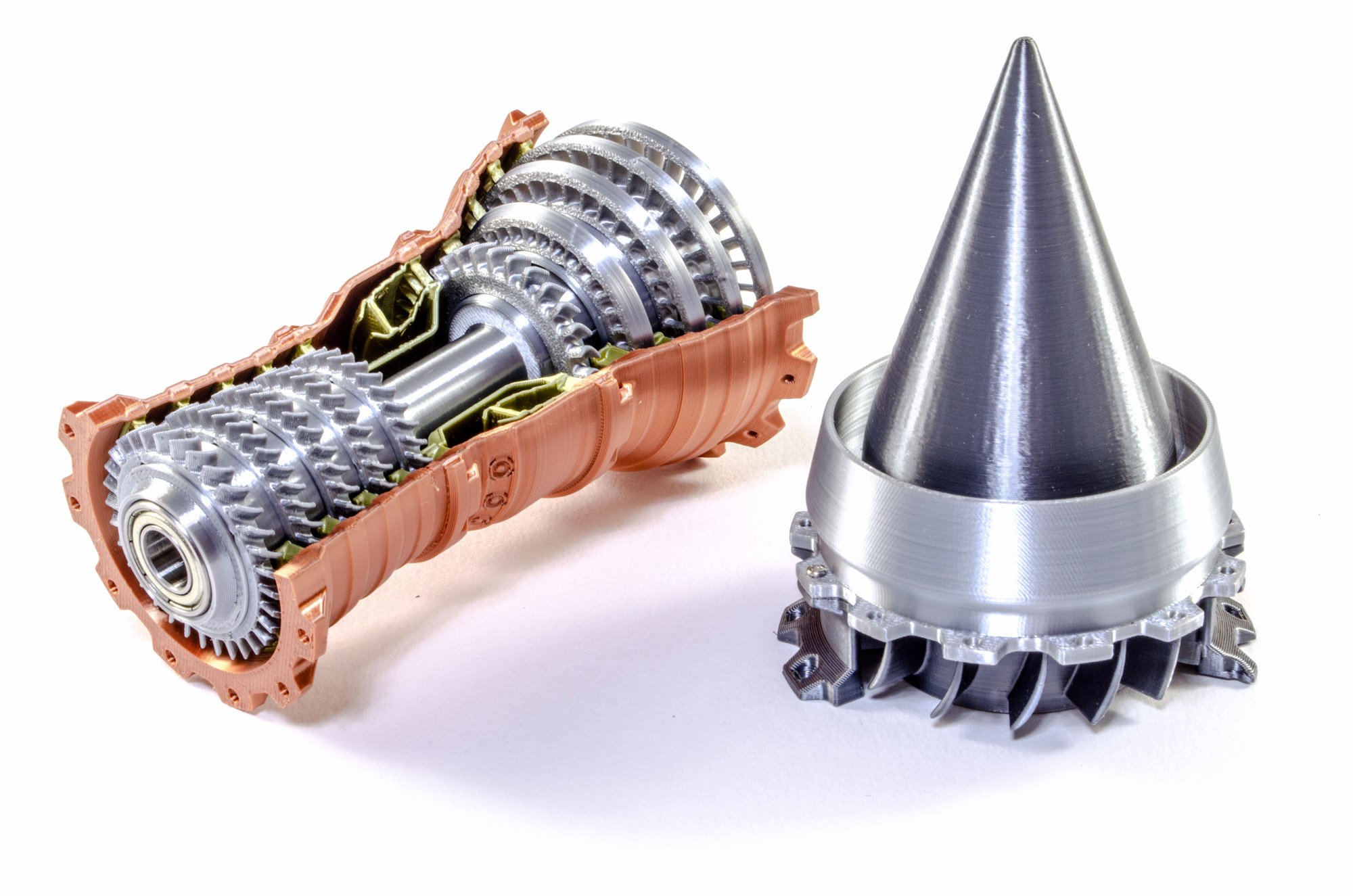
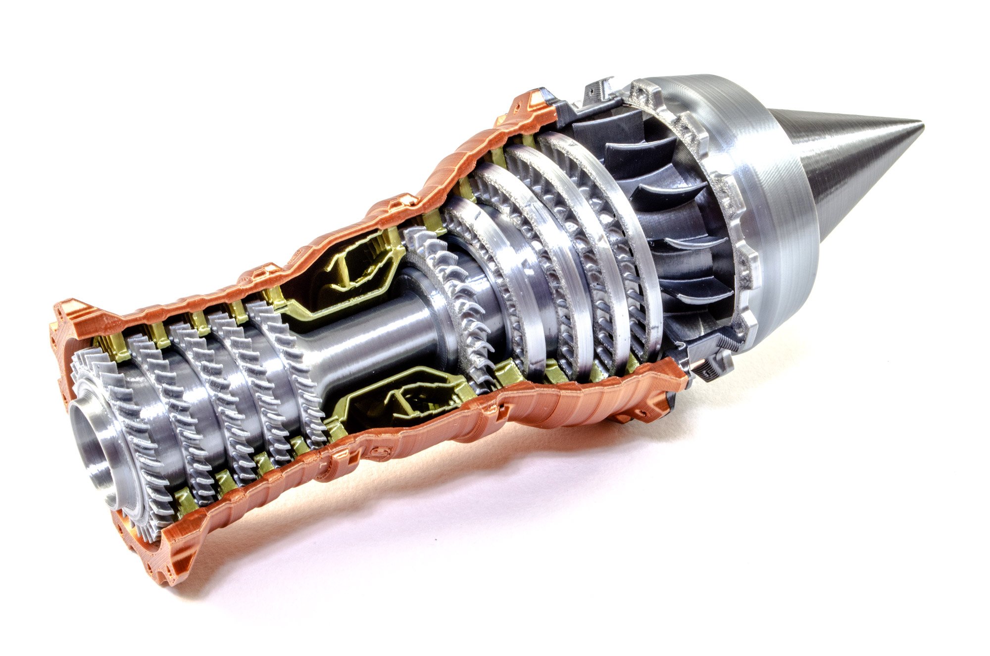
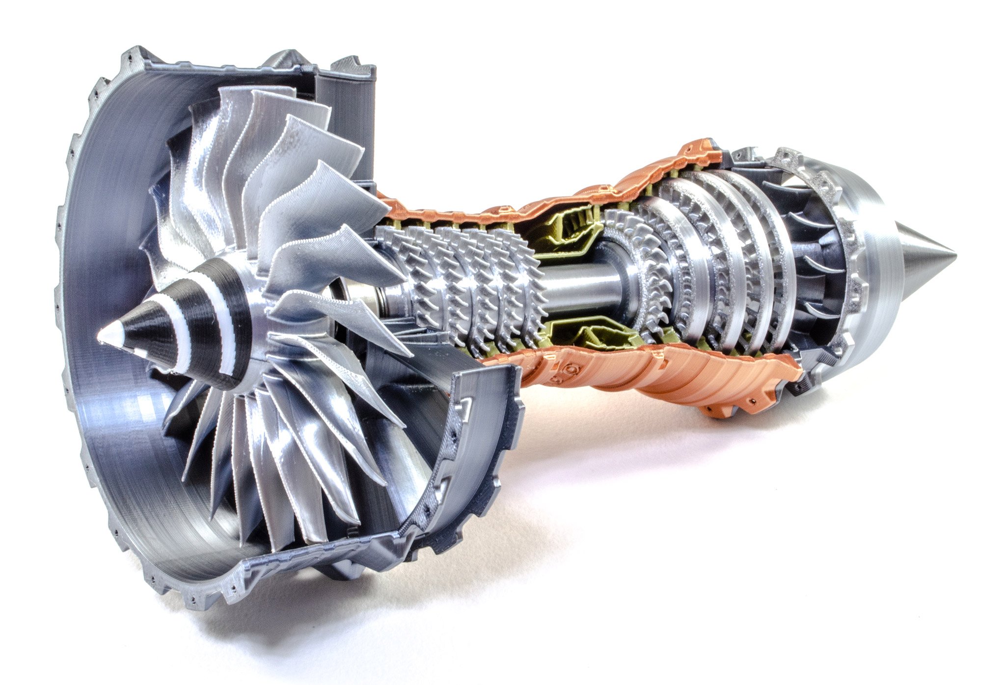
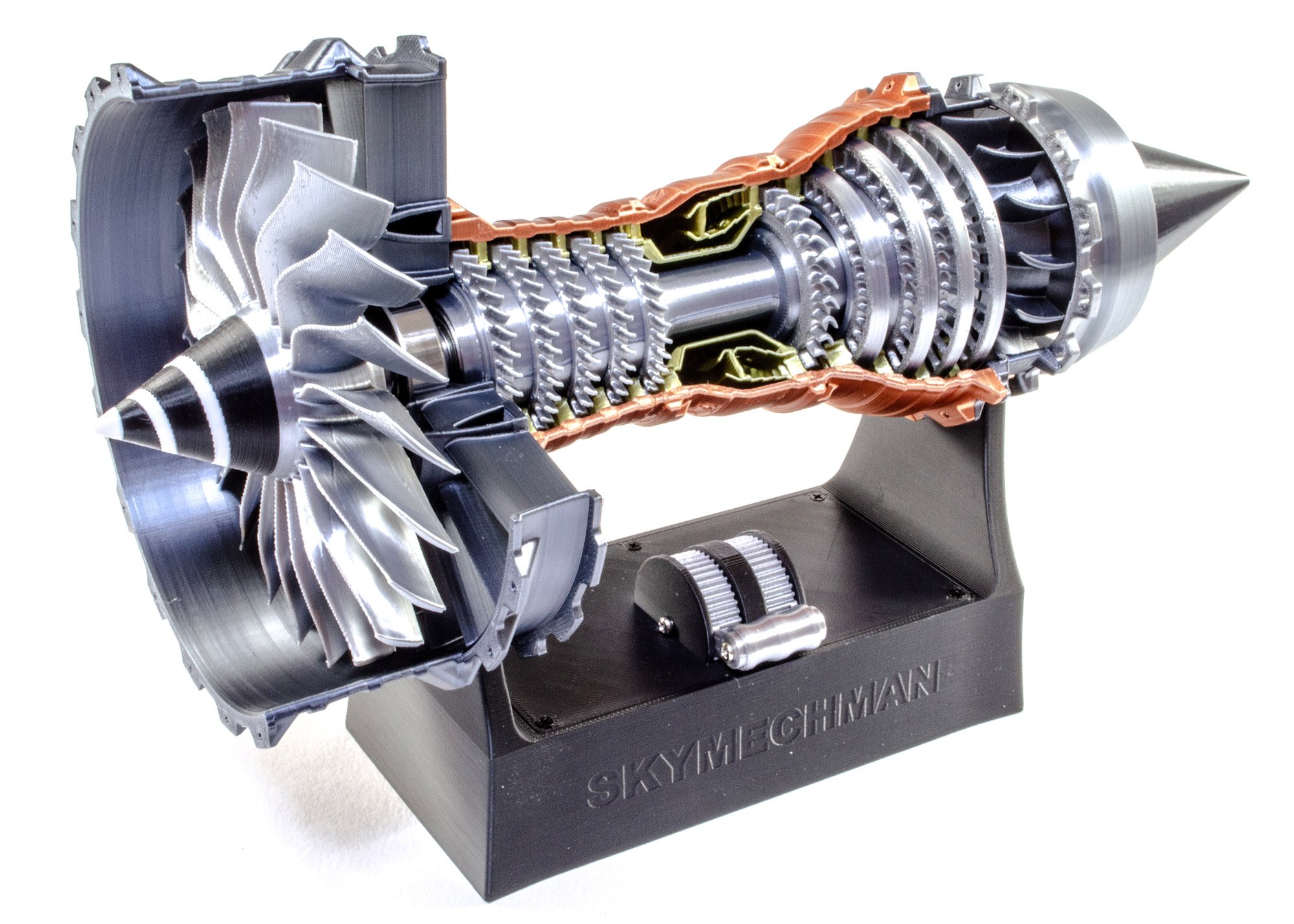
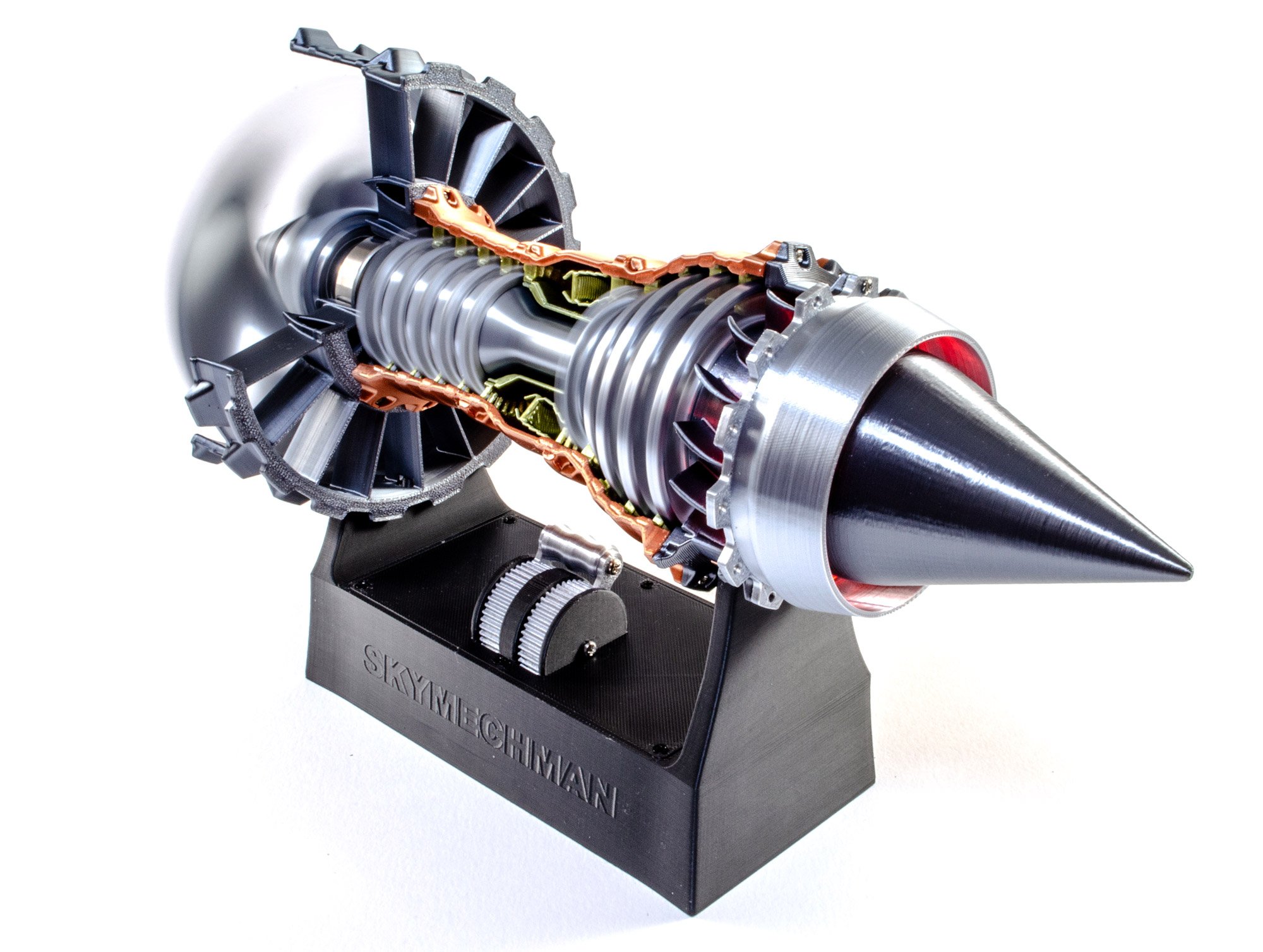
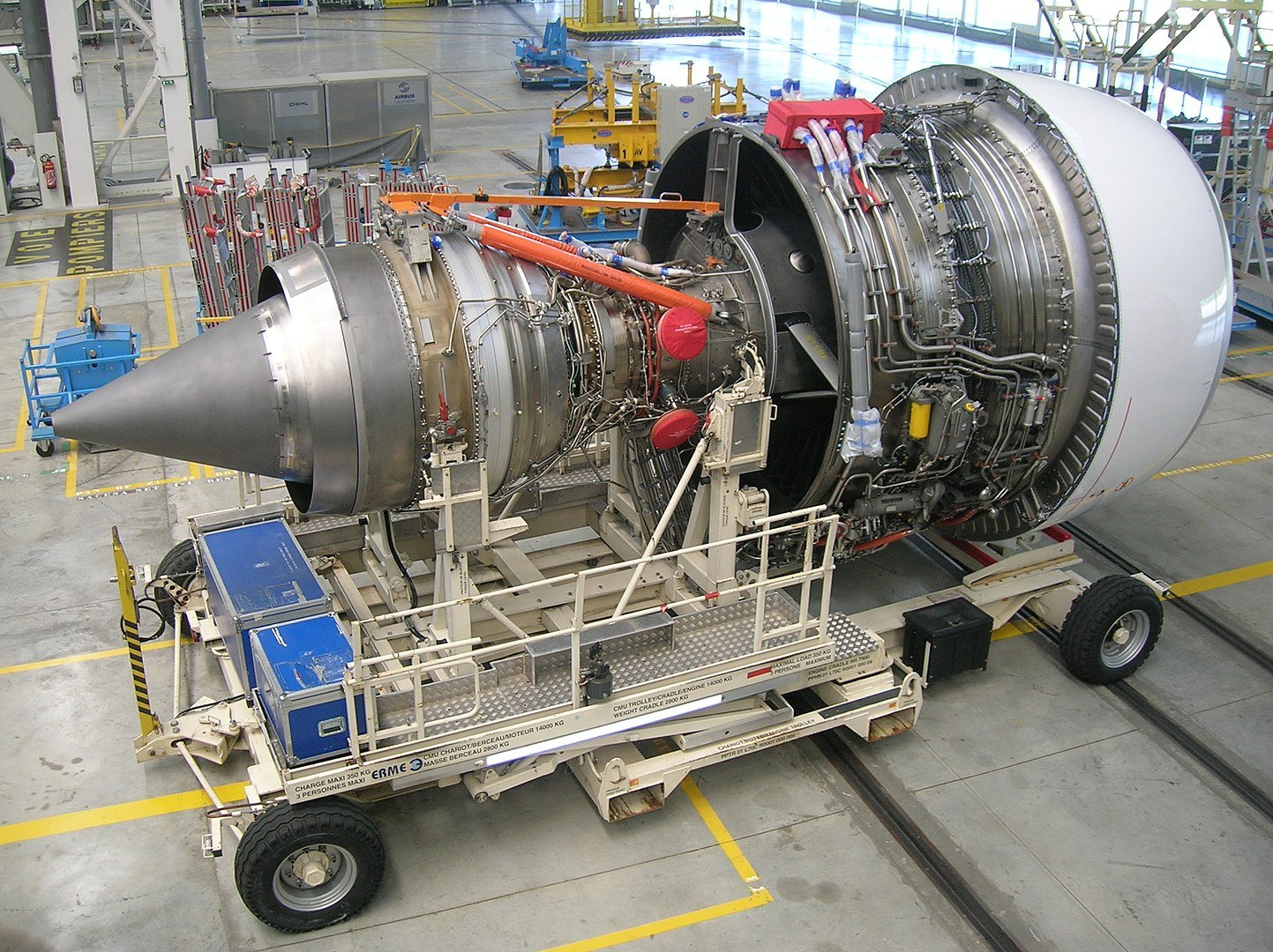
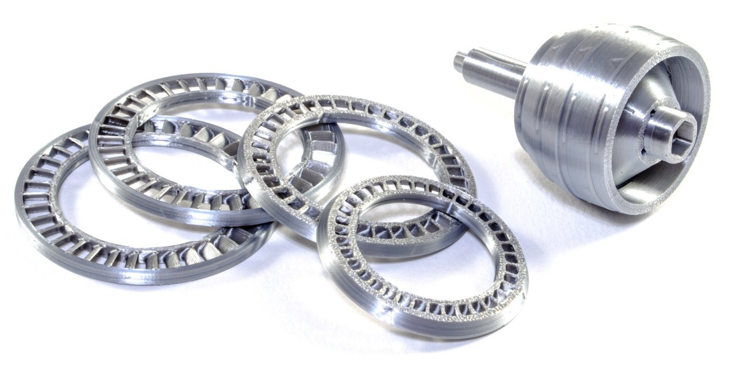
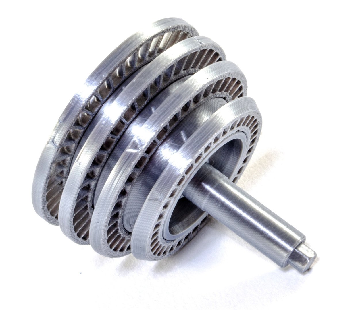
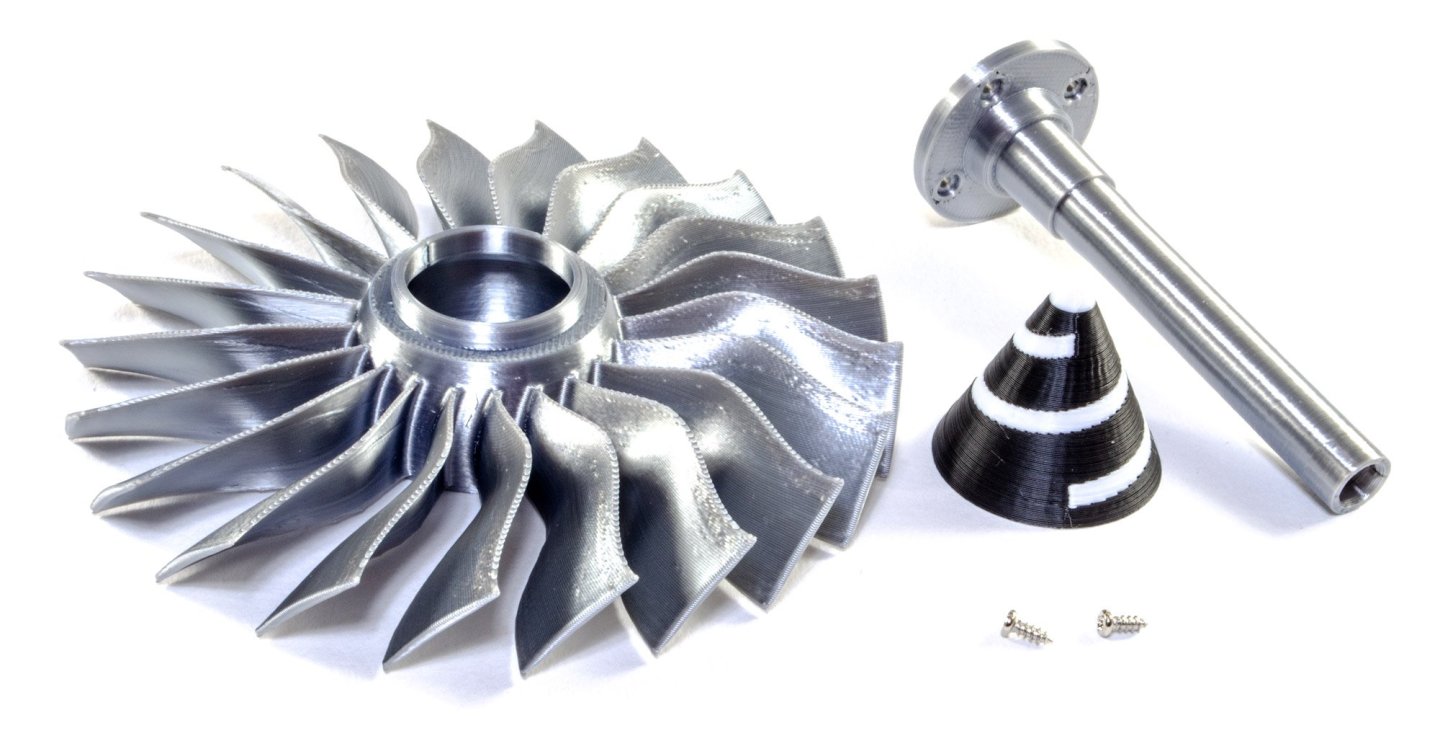
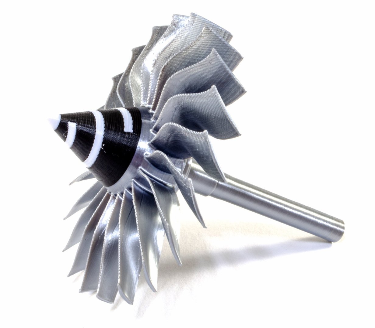
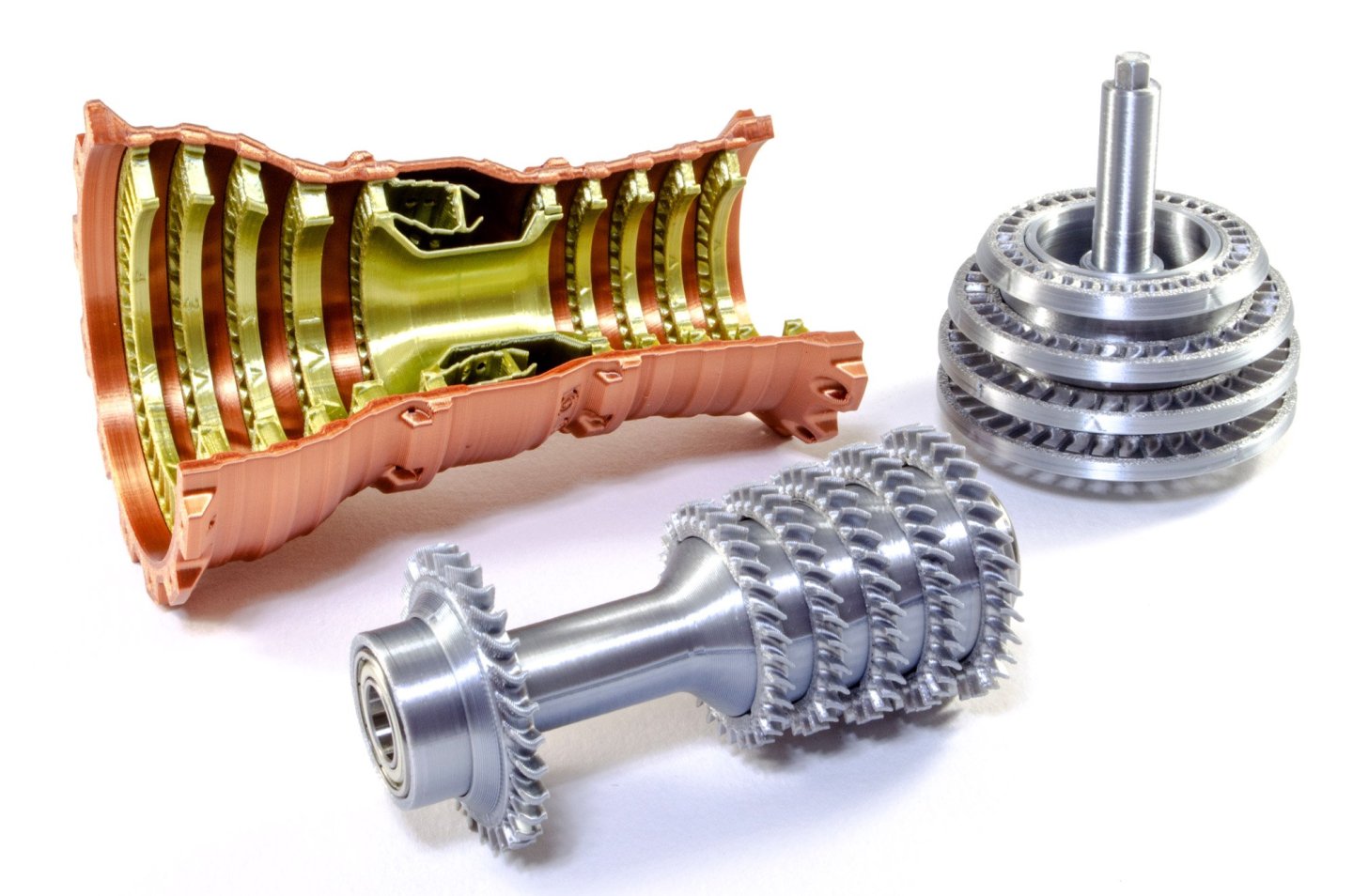
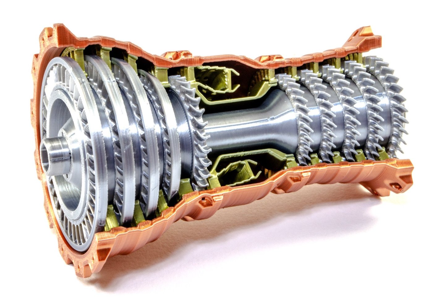
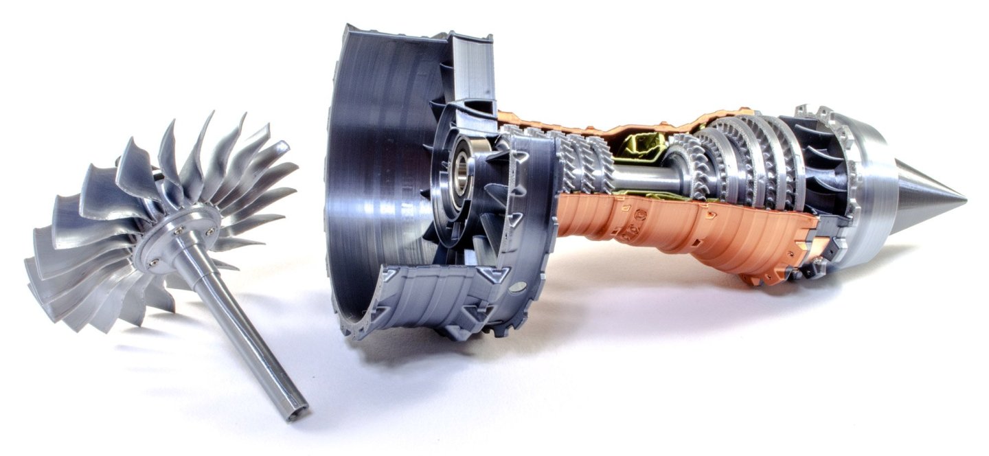
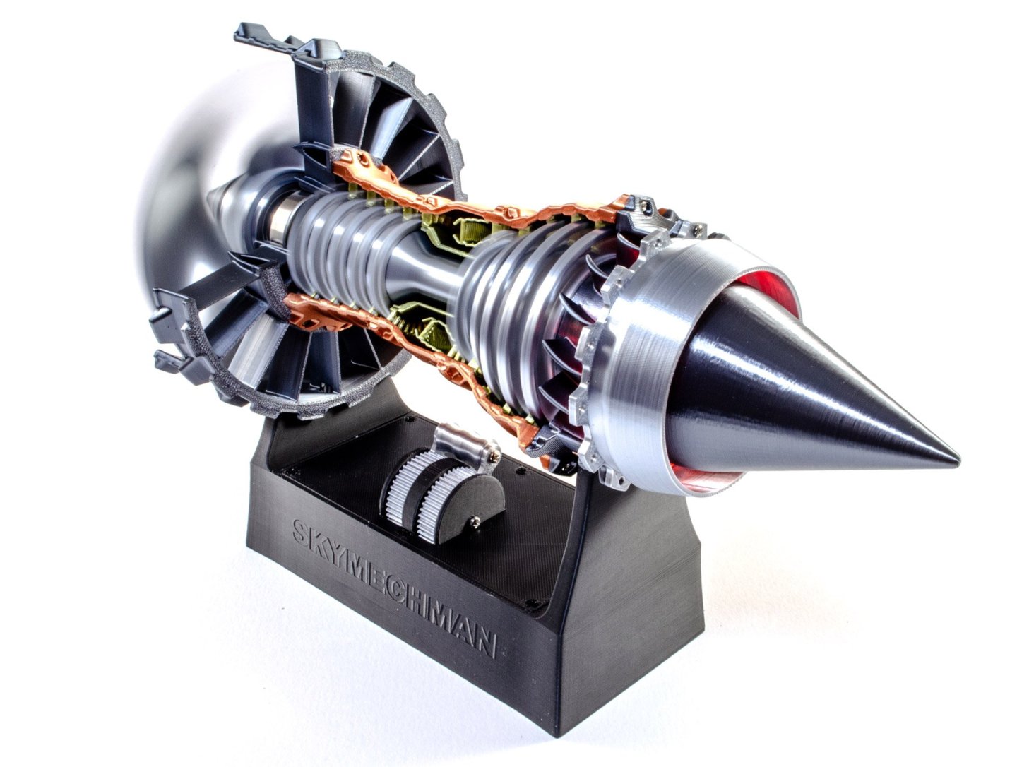
1:25 Rolls Royce Trent-900 Turbofan - SKYMECH - via EngineDIY Available from EngineDIY for $99.99 The Rolls-Royce Trent 900 is a high-bypass turbofan produced by Rolls-Royce plc to power the Airbus A380, competing with the Engine Alliance GP7000. Initially proposed for the Boeing 747-500/600X in July 1996, this first application was later abandoned but it was offered for the A3XX, launched as the A380 in December 2000. It first ran on 18 March 2003, made its maiden flight on 17 May 2004 on an A340 testbed, and was certified by the EASA on 29 October 2004. Producing up to 374 kN (84,000 lbf), the Trent 900 has the three shaft architecture of the Rolls-Royce Trent family with a 2.95 m (116 in) fan. It has a 8.5–8.7:1 bypass ratio and a 37–39:1 overall pressure ratio. The Trent 900 is an axial flow, high bypass turbofan with the three coaxial shafts of the Rolls-Royce Trent family. The 2.95 m (116 in) fan with swept blades is driven by a 5-stage LP turbine, the 8-stage IP compressor and the 6-stage HP compressor are both powered by a single stage turbine, with the HP spool rotating in the opposite direction of the others. It has a single annular combustor and is controlled by an Electronic Engine Controller. Abridged from Wikipedia The kit This is certainly the most inexpensive of the turbofan kits I've looked at here, but the first indicator of reason is the weight of the box. It's very light indeed. This kit is mostly made from 3D-printed parts, made with some very strong, metallic resins. Some sections are also pre-built. The kit is packed into an attractive and glossy black box, with a single line drawing image of the Rolls Royce Trent-900 on the side. The bus is opened via a top lifting flap. Inside the box are two trays of parts. This tray contains the main forward ring and fan (under the white styrene protector), and two pre-assembled units. These are the tail cone with its electronics, and also the display stand with more electronics. This tray has only pre-assembled unit; namely the main body which is made in a copper coloured material, with internal stators in a brass colour. Other parts here are various compressor blade rings, spinner, turbine shafts, bearings, screws, and the only tool you will need...namely a small screwdriver. Work begins by taking the six blade rings for the high pressure turbine. The first five simply slide and click onto the turbine shaft, in order of decreasing size. Arrows on all parts indicate the orientation of the parts, and the fit is incredibly accurate and positive. The last ring fits at the foot of the shaft as seen in the final image. A bearing is then pushed into each side of the turbine shaft, to complete this assembly. The next assembly is the low pressure turbine. This assembles in exactly the same way as the previous unit...arrows are used to align the turbines to the shaft. This time there are only four to fit, with two of these being identical. It's now the turn of the main impeller to be fitted to the drive shaft. Self-tapping screws are used to fit this. As a precaution, I only used absolute minimum of torque to screw the parts together, but that was probably just me as the parts are very robust. The spinner is then pushed into place. This is printed in two colours to create the spiral, which is a safety feature of the real engine. The main fan blade housing has a cutaway section so the modeller will be able to see the interior parts rotating. This is simply fitted with a bearing. The main engine body is an extremely attractive single-piece unit, as I mentioned earlier. We now take this and also push together both the high and low pressure turbine units. The fan unit actually fits quite easily into the engine body. There is some flex in the materials and a small push allows the fan to be quickly inserted without any fuss. The tail cone is called the 'power module' in this kit. That is because it holds the drive motor and all of the electronics associated with rotating the engine. This and the main fan unit fit together by means of a keyed slot in the shaft. More self-tapping screws are now used to assemble both parts. The main fan housing unit is now screwed to the turbofan body. The fan assembly then simply pushes into the engine to lock it in place. There's no connecting wires between the engine and the base. Instead, two copper contacts on the power module, are used to transfer voltage from the base to the engine. These sit together with some positivity, and the engine can then be powered. When the lever is first moved, it will click, and the red LEDs at the tail, will light. Push further and the engine begins to rotate. The speed can be controlled depending on how far you push or pull the lever. Operation is fairly quiet too, and unlike the other engines, this one doesn't have the pre-recorded jet engine sound. It isn't missed or needed though. You can see the fan in operation in the bottom photo. OPERATIONAL VIDEO Conclusion This little kit took less than an hour to build, and was actually a very satisfying little project and highly enjoyable. Being 3D printed was no detriment to the fun and final appearance of the completed model, and of course, those materials help to create a relatively cheap way of building your own little turbofan engine for your office desk. The kit itself is high quality and fits like a dream. The only thing I'd do myself would be to make a Rolls Royce display plate to cover the manufacturer name on the base. My sincere thanks to the folks at EngineDIY for sending out this great little kit for the purposes of review here at Model Ship World. To buy directly, click the link at the top of this article.


-
I'm unaware of that. The system isn't accepting email addresses as logins. This is something the software creators have picked up on, and are changing it, wholesale for all forum members. If I try to login, I'm asked for username and password. You're saying yours asks for email? Can you screenshot that? I just added a new test account here and it's asking for username and password, as per this account.
-
Good evening, all! The software we use is currently version v4.x. We are edging, month by month, closer to V5. When we hit a new number, these are usually massive revisions, and we've only had one of those on MSW in the past 10yrs. It is anticipated that within the next months that we will need to upgrade to the new version. To improve security, we will all have to login using our registered email address. At the moment, we simply use our username. EVERYONE....please take note of the registered email address on your MSW account, by looking at your Account Settings. Take note of it. Maybe you no longer use your registered address. If not, change it. I will be prompted to reauthorise your account. That's all there is to it to be prepared for the change, when it happens. When it is imminent, I will give you a further period of notice. Maybe you no longer have access to that email account. The same will apply. The short of this is PLEASE TAKE NOTICE OF YOUR REGISTERED EMAIL ADDRESS and correct it if it's not current.
- 14 replies
-
- 23
-

-

-
That really does look excellent, and your work is so clean.
-
I’ll watch the new videos tonight.
-
Kit review Vertical Steam Engine Kit - Enjomor - from EngineDIY
James H replied to James H's topic in Non ship-related reviews
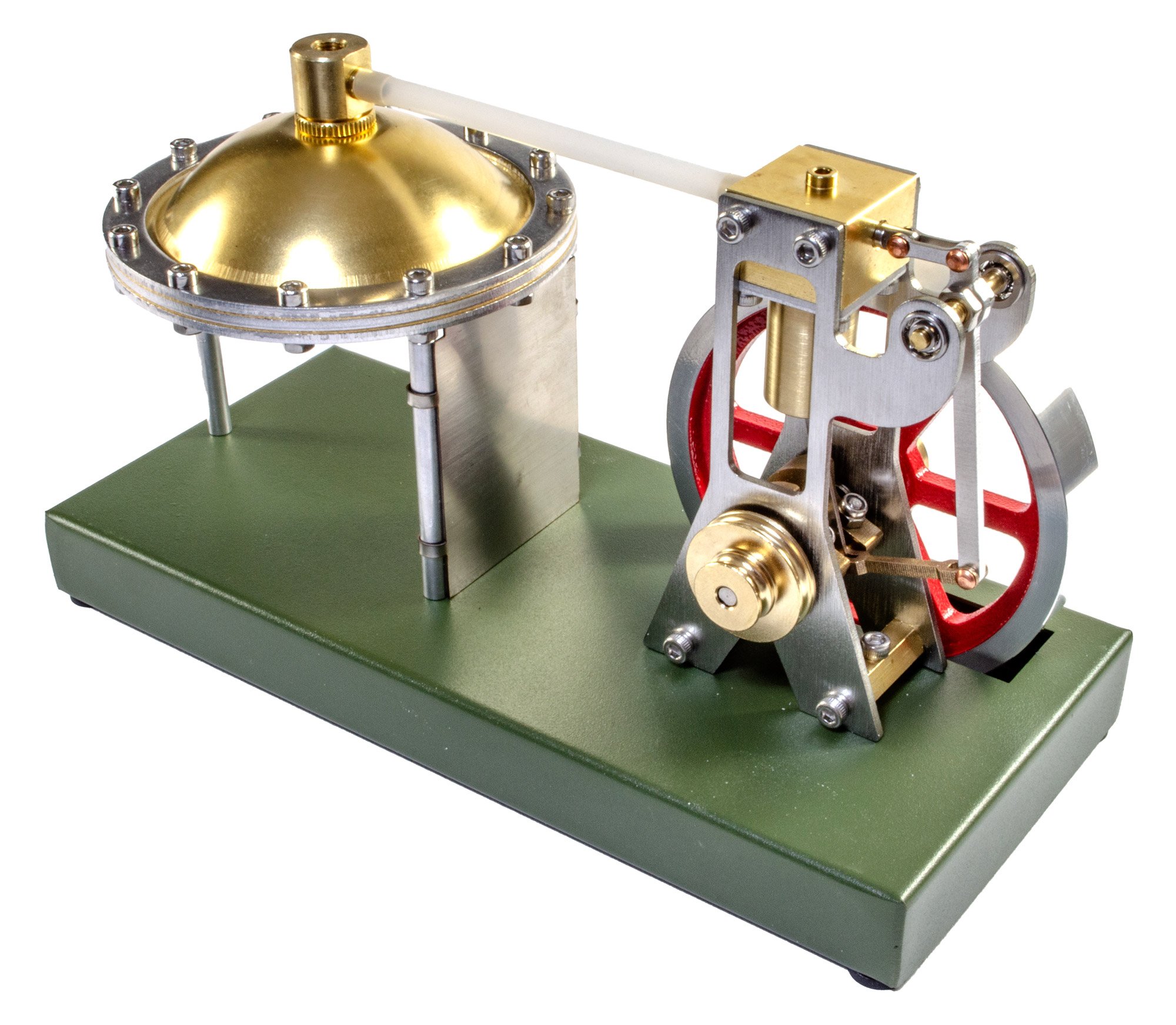
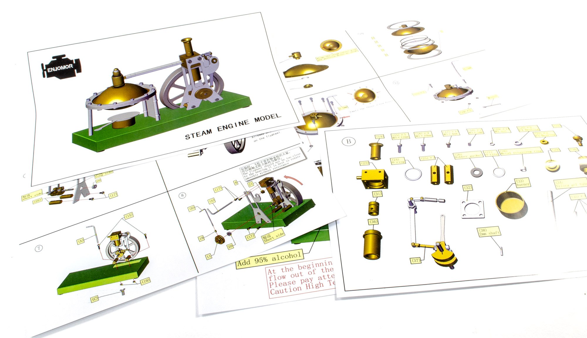
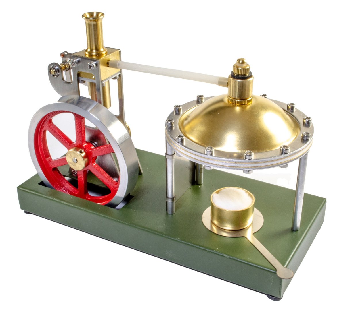
25ml of water was injected into the boiler and then the safety valve fitted. The fuel pot was filled with ethanol and the synthetic wool was soaked thoroughly before lighting. It took about 2 minutes for the boiler to reach pressure, and the flywheel was turned a few times before it set off by itself. When the boiler has been running for a short while, it can be stopped by putting the flame damper tool over the fire pot. The engine stops very quickly once you do this. Conclusion This is a perfect little project for anyone new to building steam engines. The kit parts are perfectly machined and fit together beautifully. Engine operation is also easy to understand with the bare minimum of user interaction needed to ensure smooth operation. This is also a nicely priced little kit and the finished project does look quite ornamental too, so it'll look real nice on your desk or shelf. This is one I absolutely recommend! My sincere thanks to EngineDIY for sending this little model to be built and reviewed here on Model Ship World. To purchase this directly, click the link at the top of the article.
-
Kit review Vertical Steam Engine Kit - Enjomor - from EngineDIY
James H replied to James H's topic in Non ship-related reviews
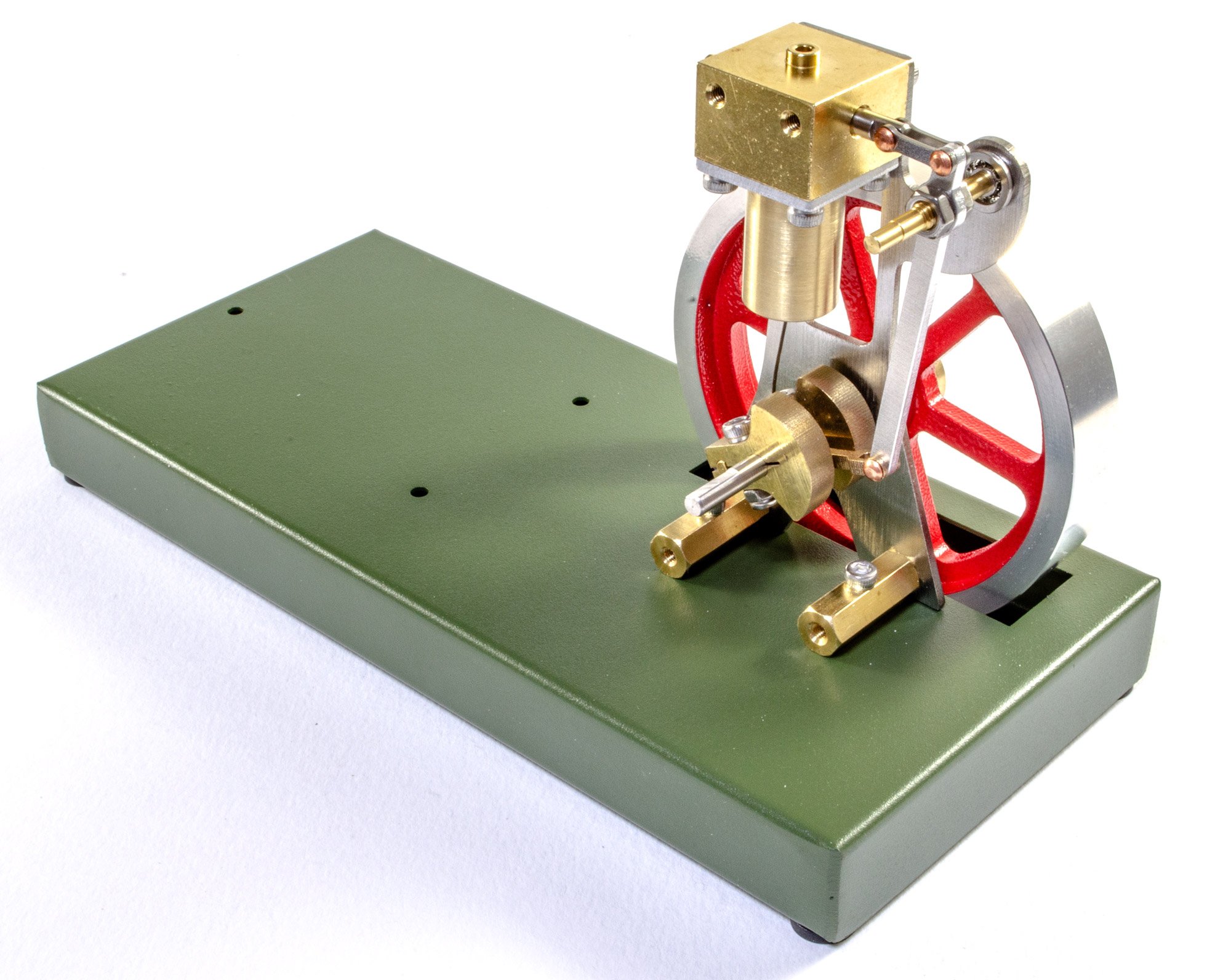
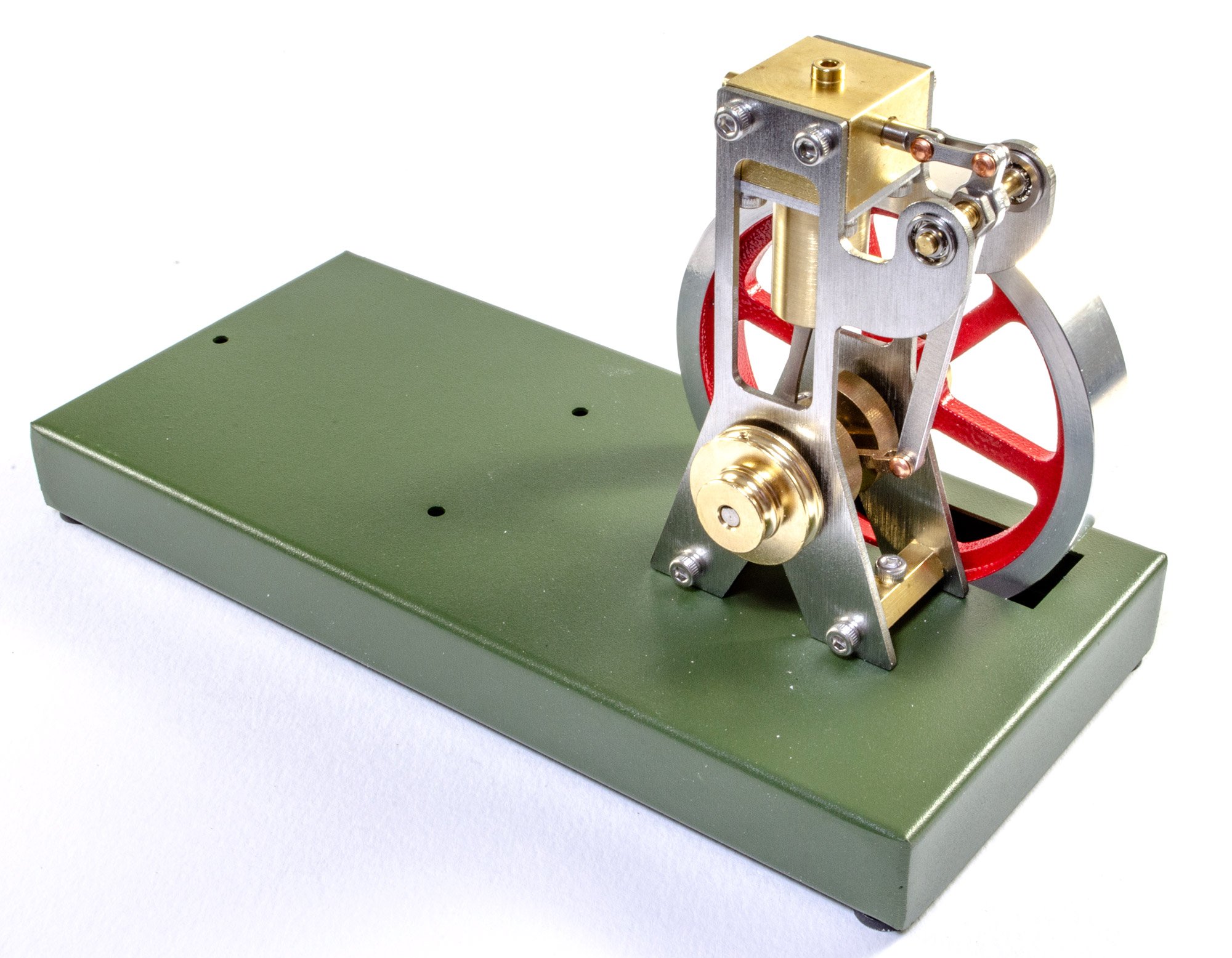
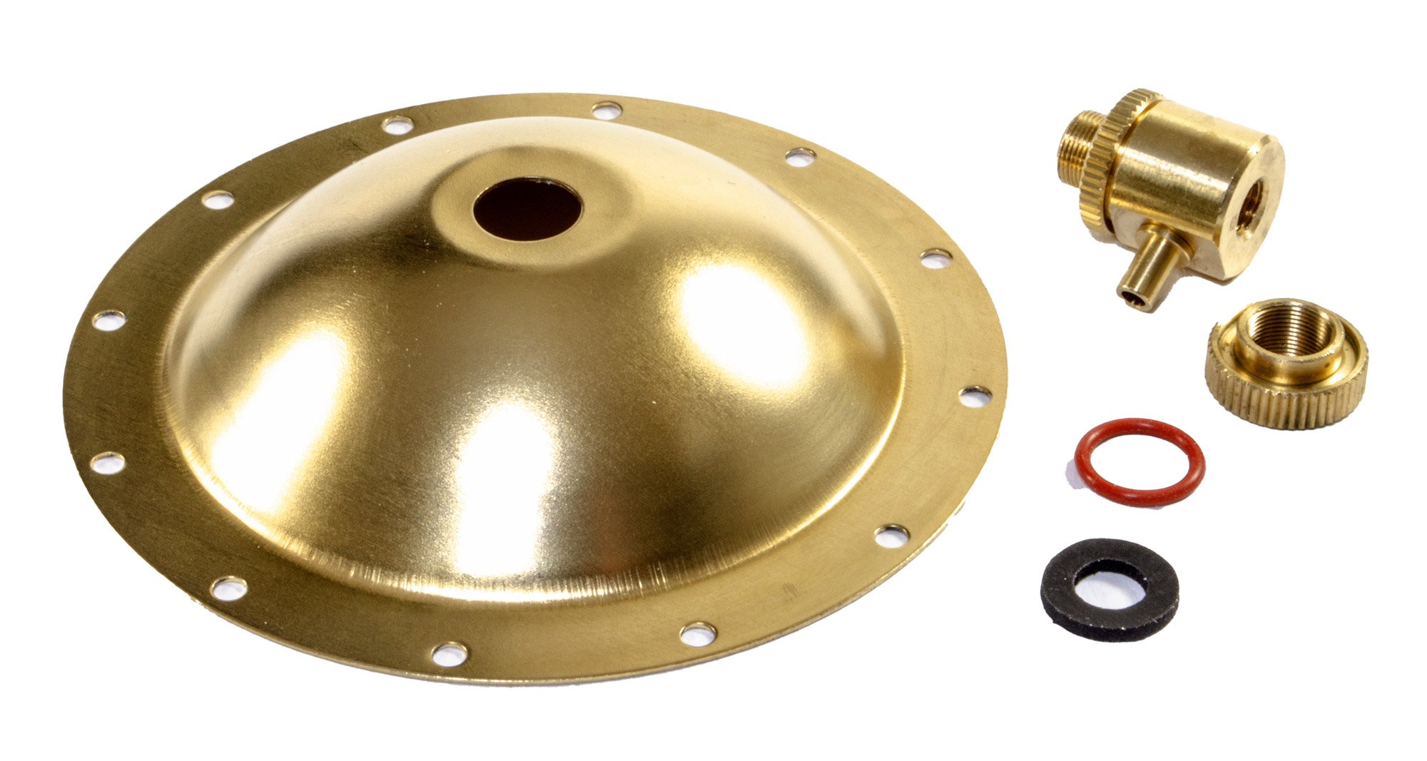
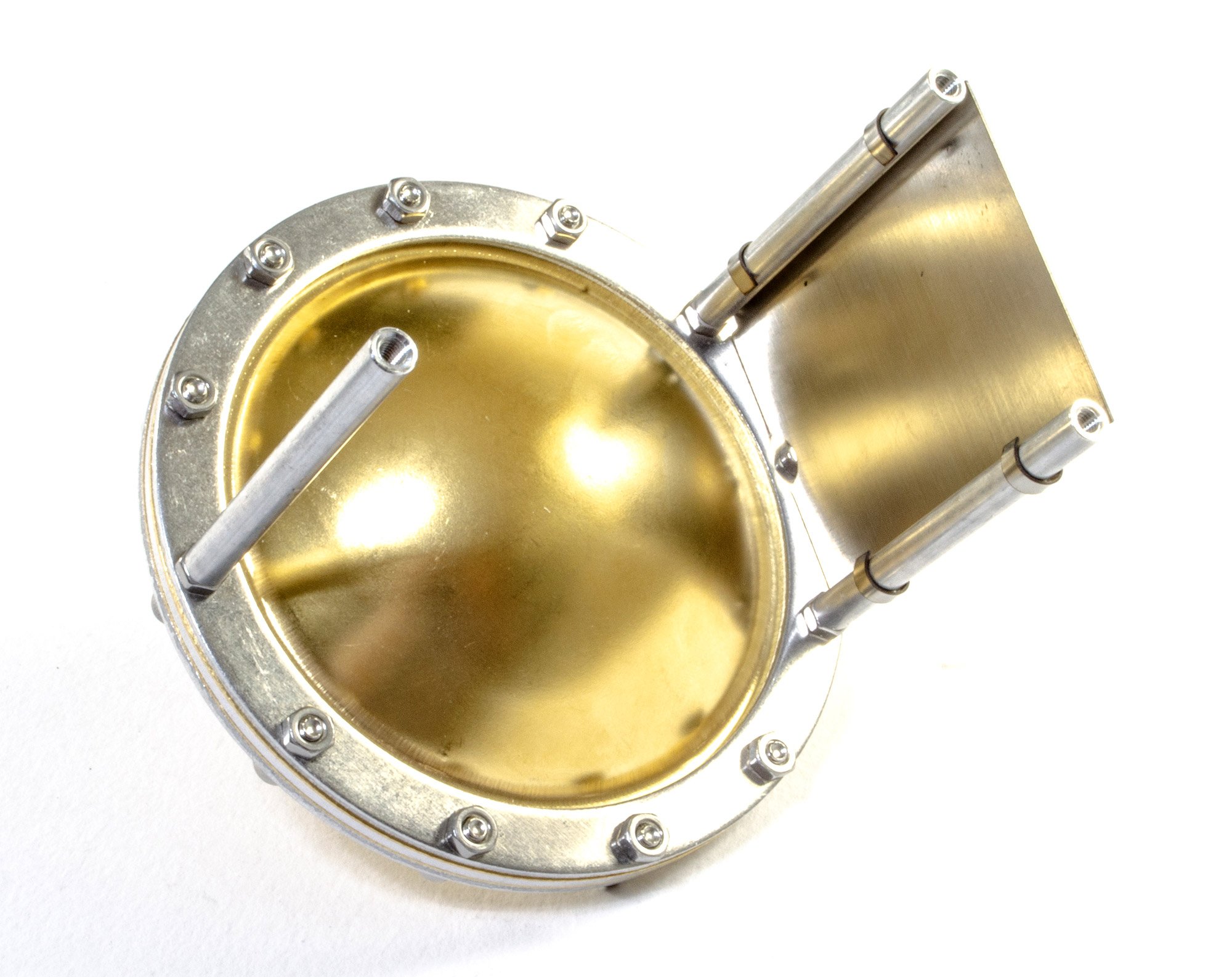
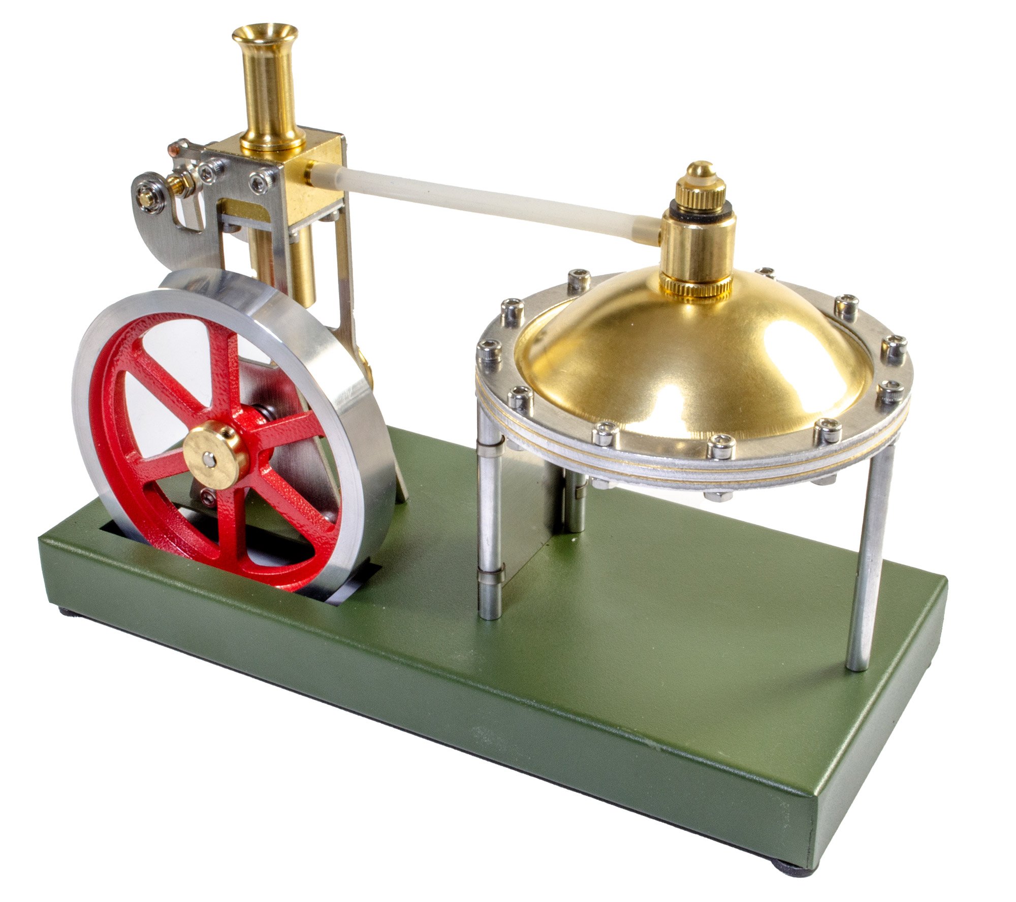
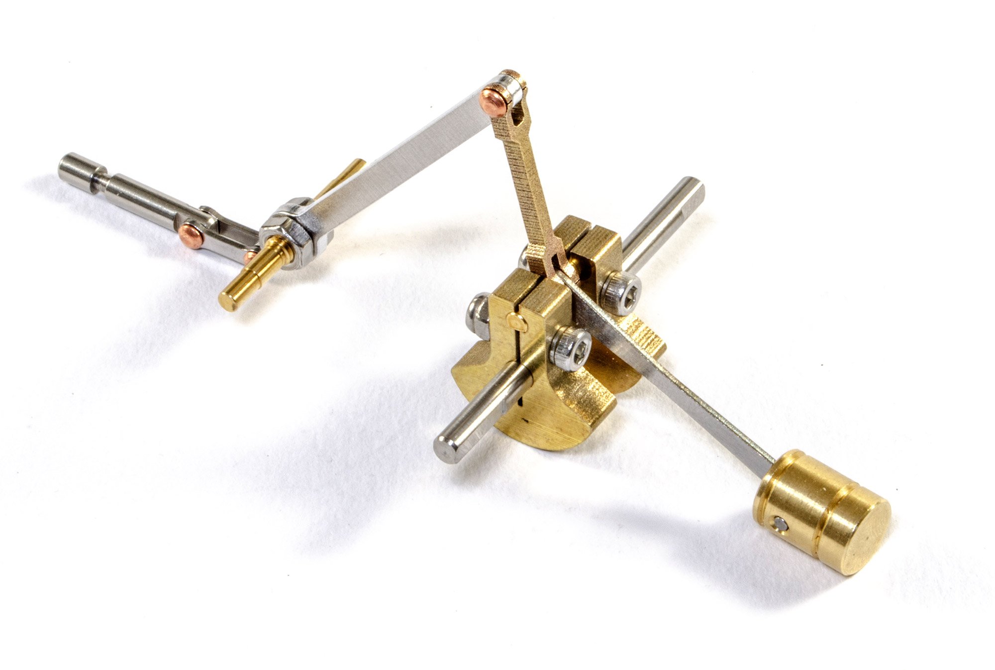
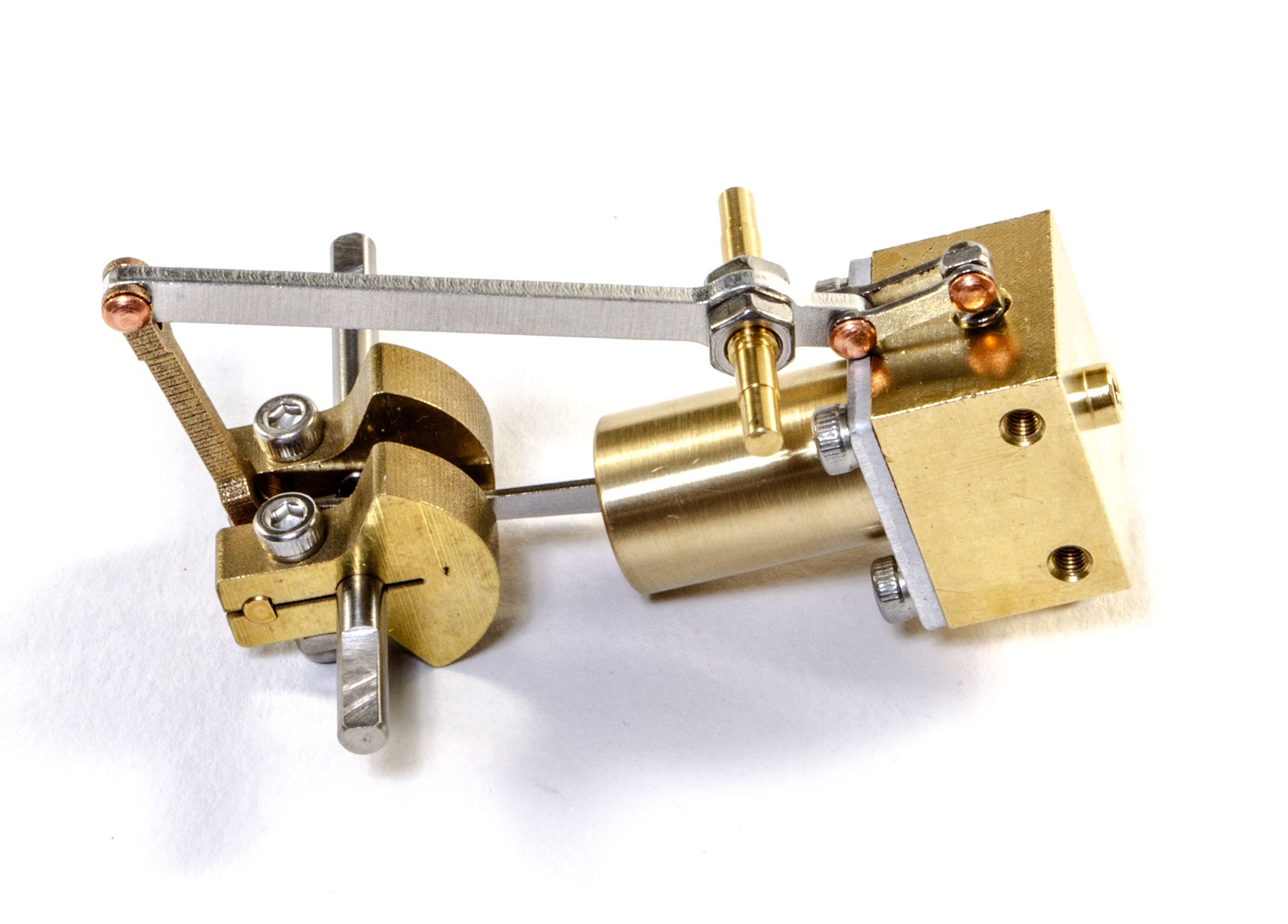
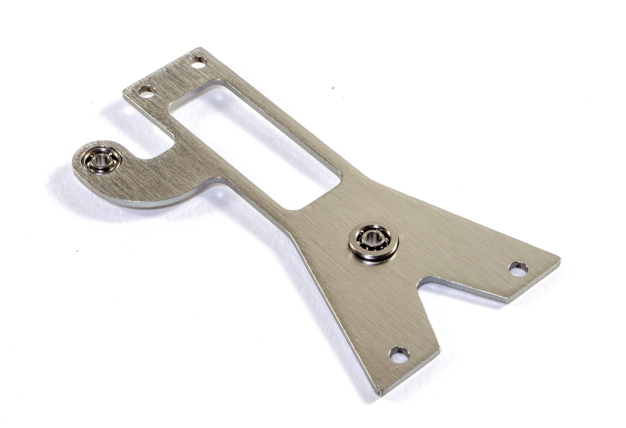
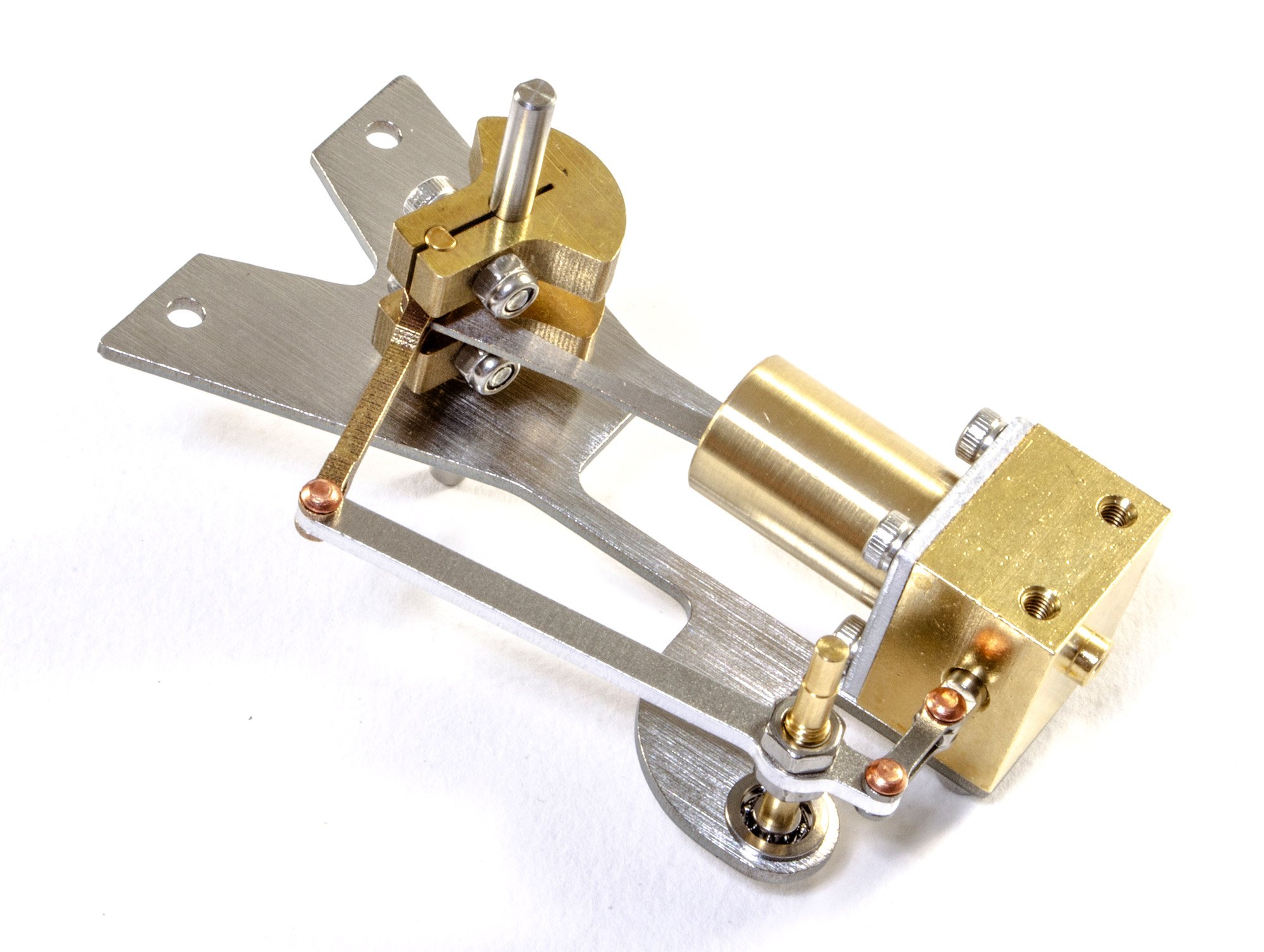
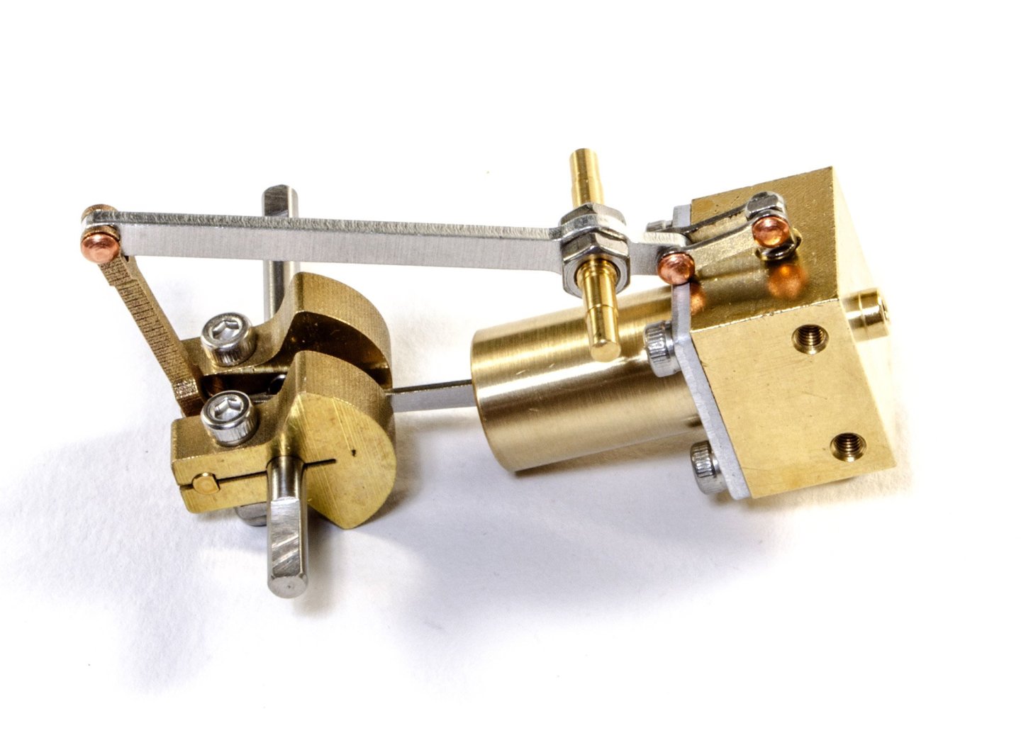
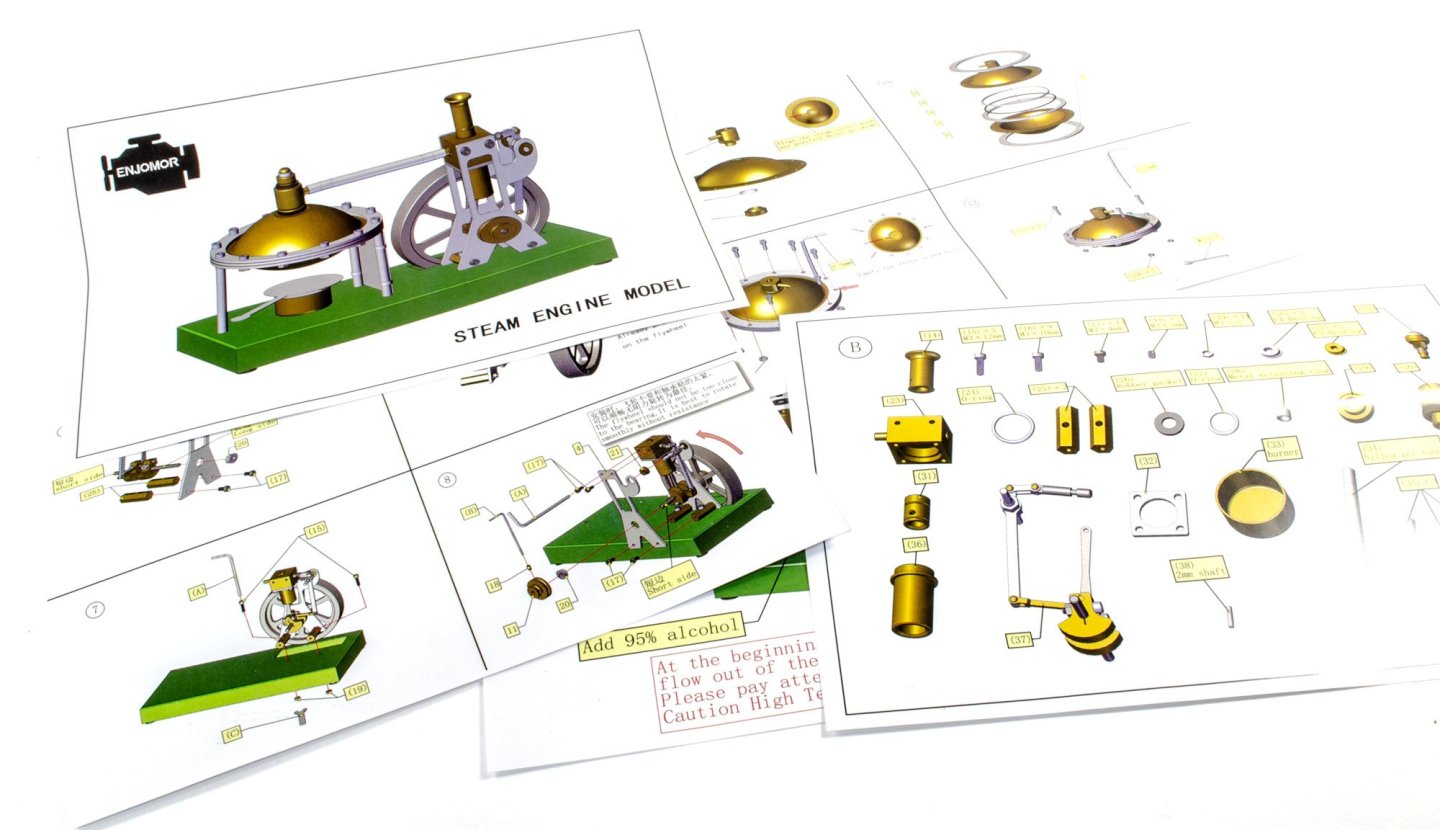
The flywheel is now attached, as are two brass mounts which will be used to secure this assembly to the base. The whole assembly is now fitted to the base. The flywheel is checked for clearance all around. The other bracket is now fitted to the main assembly and then drive belt wheel added. At this point, I have to tell you nothing is attached to this. The kit is simply to show you how this simple type of steam engine operates. The boiler for this is comprised of two brass discs, secured with metal flanges and an internal rib and rubber gasket. On top of the boiler is a safety valve which will operate if the boiler goes over-pressure. Once the boiler is made, three standoffs are first fitted to the specific bolts that are used in certain circumferential positions. A firewall is then slipped between the two closest. This is to protect the main piston assembly from the alcohol pot. This boiler is then mounted to the base, and a silicone tube used to link the piston to the boiler. The condensate chimney and safety valve are fitted. Lastly, the alcohol pot is added. This is actually magnetic, meaning it won't flop about on the steel base, once it's lit and in operation. The part you see sat underneath is actual a flame damper, used to put out the pot. This will not sit here during operation. Now it's time to run the engine...


-
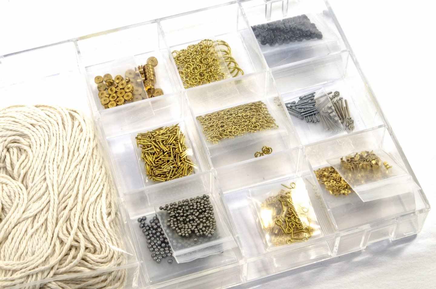
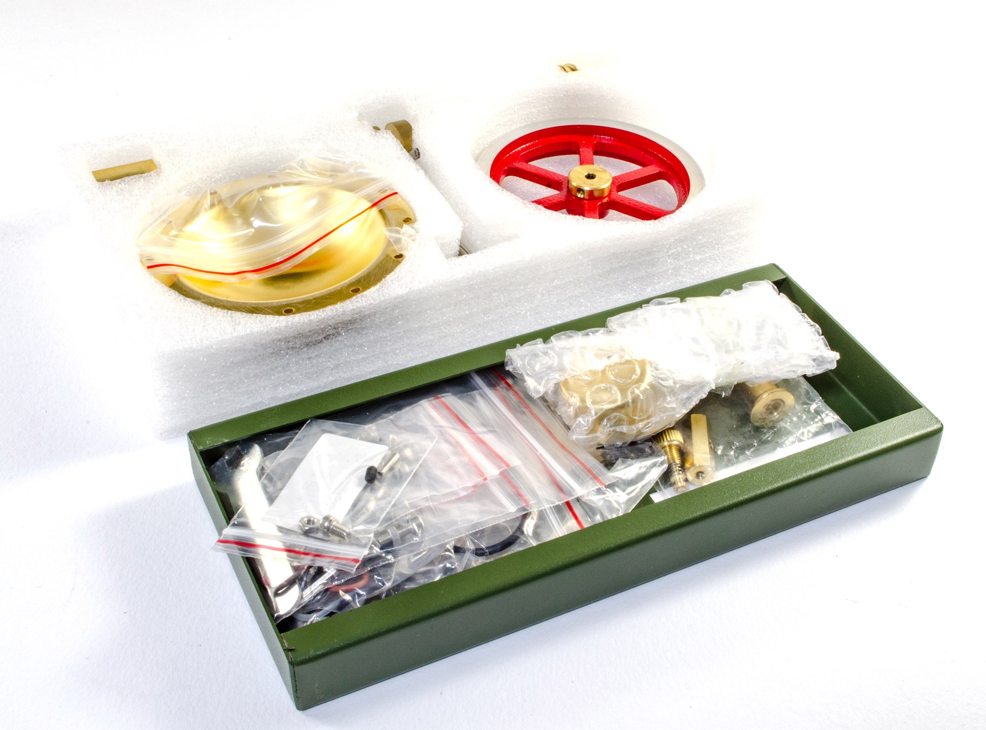
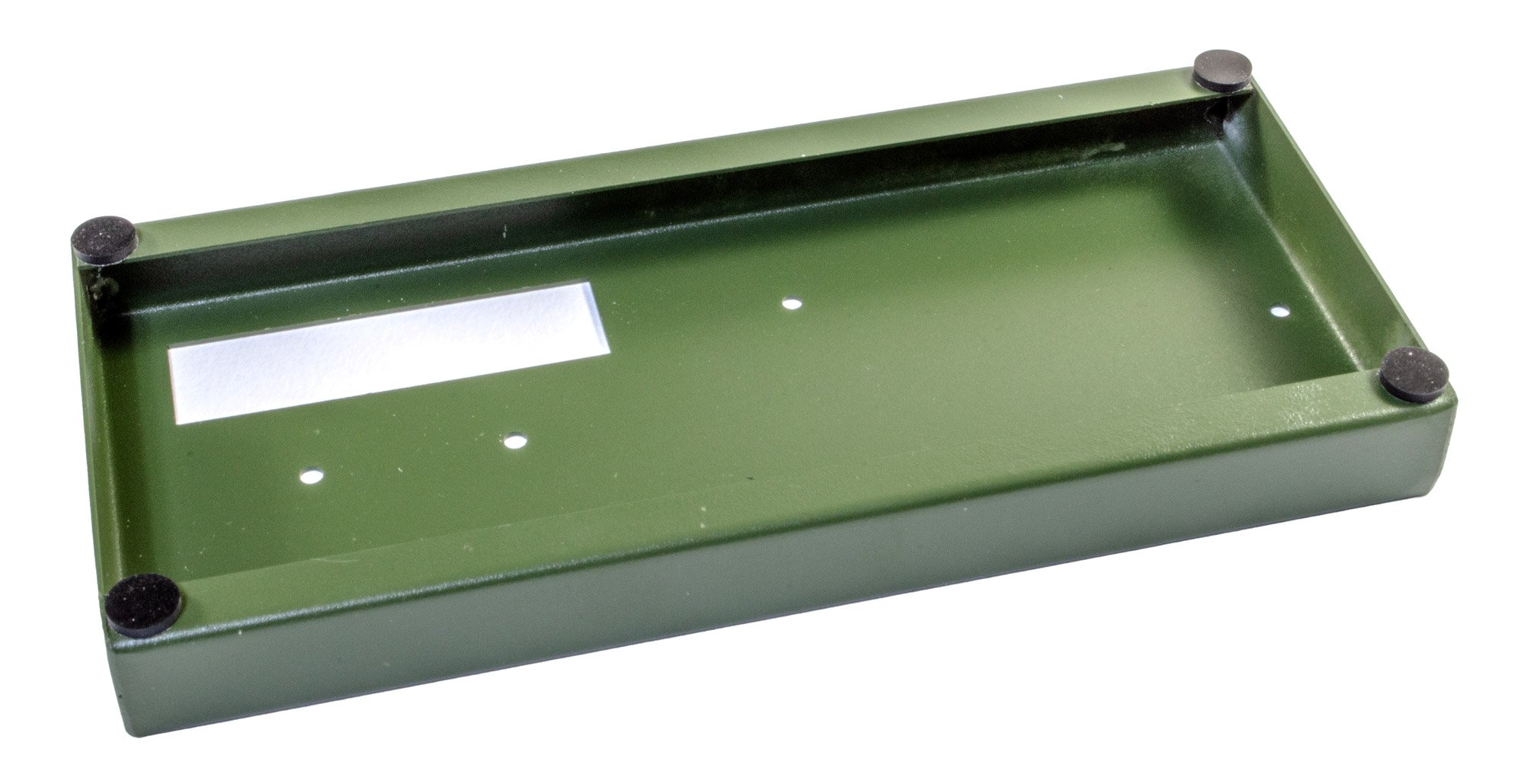
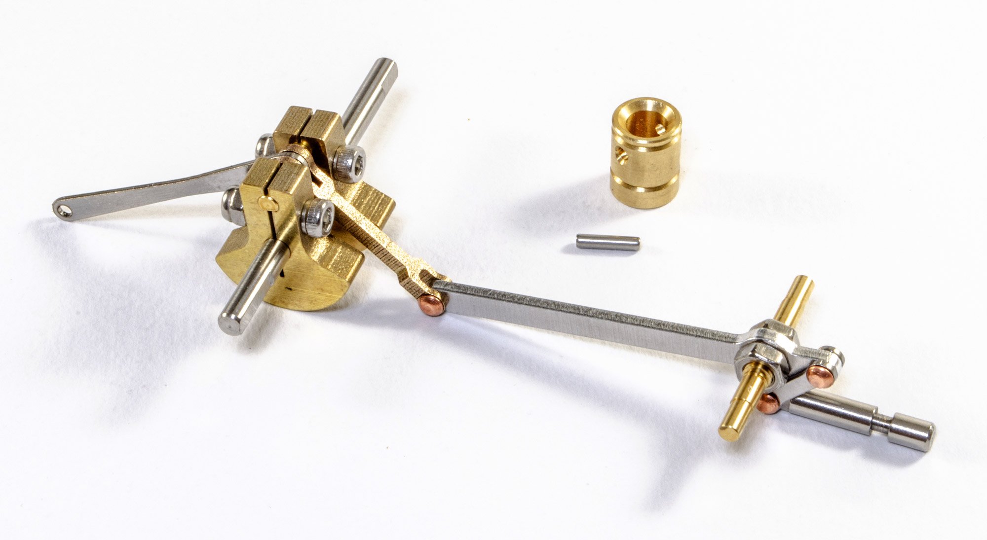
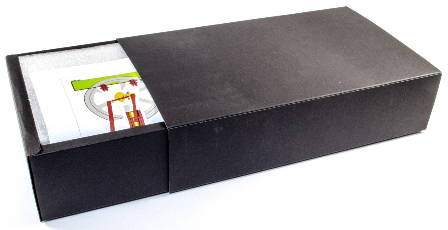
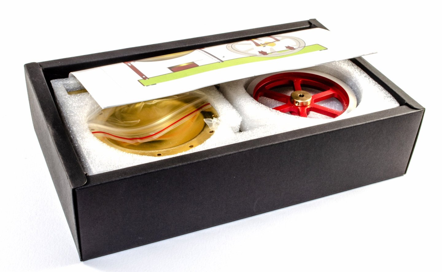
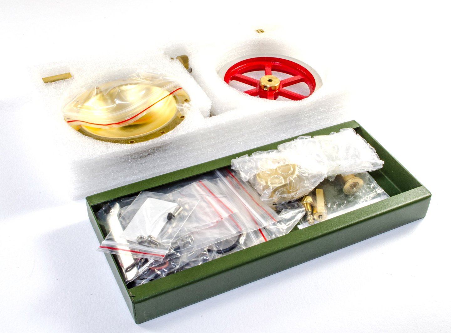
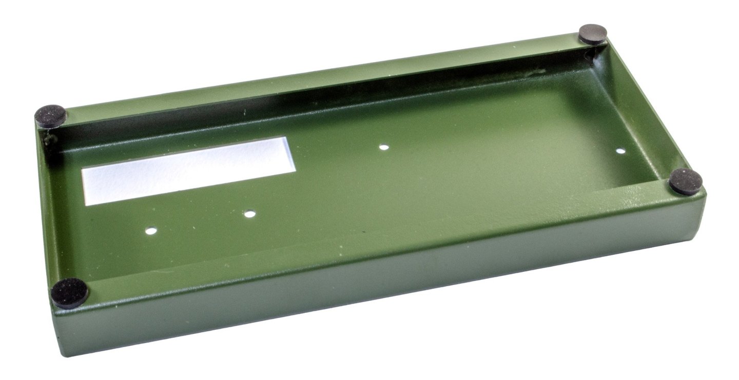
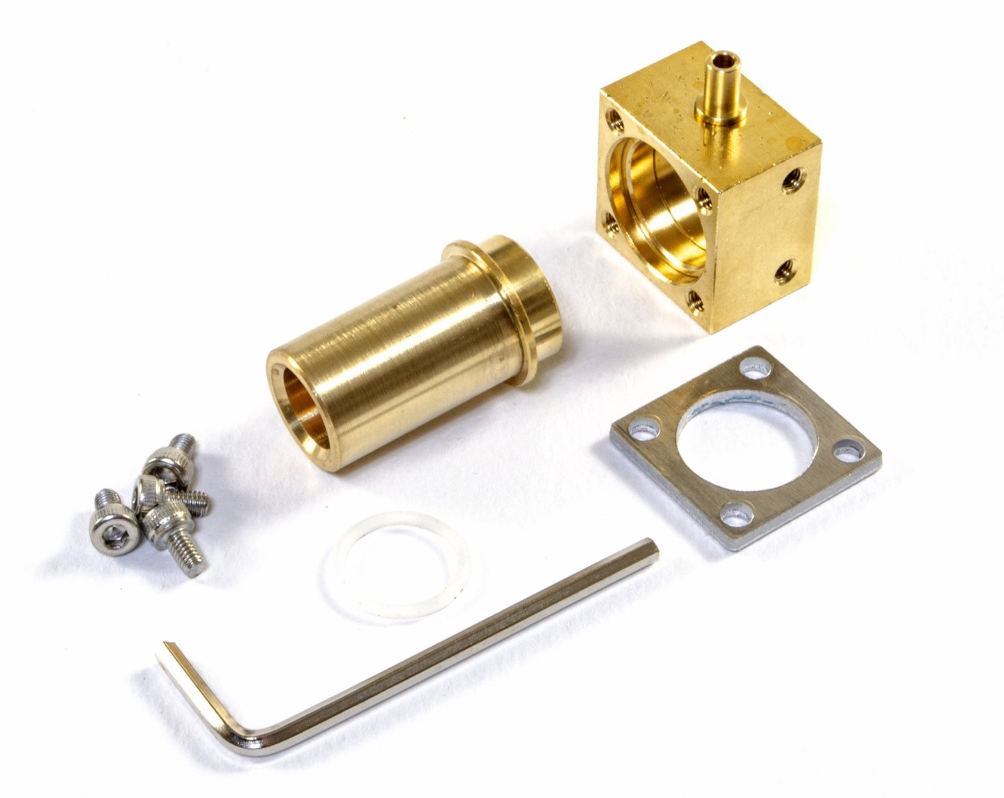
Vertical Steam Engine Kit - ENJOMOR Available from EngineDIY for $129.99 A vertical steam engine is a type of stationary steam engine with a vertical cylinder and cylinders located directly above the crankshaft. They are also known as "hammer" or "steam hammer" engines because of their similar appearance to the steam hammer, a common 19th-century steam technology. Vertical steam engines became more common in the 19th century as steamships grew in size and tonnage. This was because they were simpler, more efficient, and easier to maintain than other engine designs. The kit This is the simplest of the steam engine kits that I've looked at here, but one that's quite elegant in its operation, plus this could sit easily on a shelf, due to its narrow footprint. The kit comes in a fairly small and plain, black card box, with a single tray of parts and the remainder of parts, tools and fixings, found underneath the white foam tray. A series of colour sheets is included for the instructions, guiding you through everything you need to know to build this simple kit. The base for this, as stated, is quite narrow, and made from tough paint-coated steel. The colour is quite neat too, having that industrial feel to it. The very first thing that needs doing is to attach the self-adhesive feet to each underside corner, as shown here. The pushrod and counterweight assembly is now coupled to the piston and locating pin. It's now time to build the piston chamber. The machined brass sleeve is first fitted with a silicone ring and then the pair inserted into the steam receptor box. These are then coupled with a steel retainer, held in situ by four screws. This assembly is now attached to the pulley. A little oil is used to lubricate the moving parts. Two mounting brackets are included. These are first fitted with the appropriate bearings, and then this bracket it mounted to the piston/hammer assembly. More in a moment...


-
Ah! It does look very nice indeed.
-
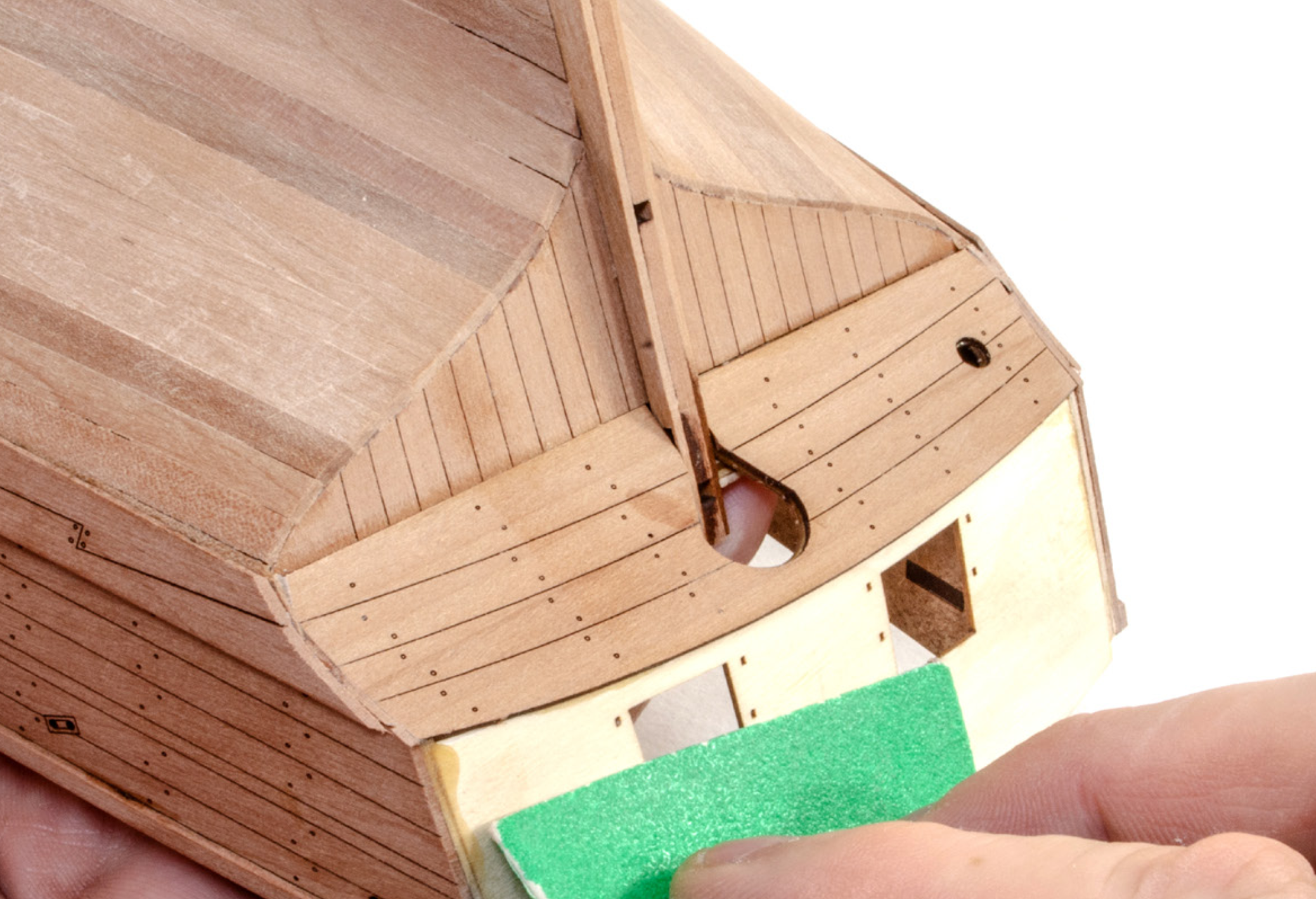
Conclusion This would always be an ambitious project and I think Artesania have pulled it off quite well. They certainly have reproduced pretty much the entire interior of Victory in a way that no other company has yet attempted to do so. The detail levels are quite extraordinary and will certainly add up to be one seriously long and rewarding project. This is by no means a project that I could consider for a newcomer, no matter how tempting the subject is, and the experience of building that interior. The hull on this kit is single planked, so you will need to take that into account when you consider your own abilities. The videos are wonderful at showing how the hull is planked, but you will need to be attentive to them and be confident in your approach to replicating what you are shown. With some experience, this model will doubtless build up into a masterpiece. There aren't the same generic fittings on this kit as you would see on some contemporaries, and even others from AL's own range, and the finesse in detail throughout is at another level. This isn't a cheap kit, but £/$ per hour, then as a long term project, you will definitely get your money's worth on getting yourself one of these kits. Of course, there's always the voyeuristic side of modellers who like to see the interior stuff, and this kit satisfies that need in bucketloads! I do have a few extras for this kit and I will review them shortly. My sincere thanks to Artesania Latina for sending this kit for the purpose of review here on Model Ship World. To buy this kit directly, click the link at the top of this article.

-
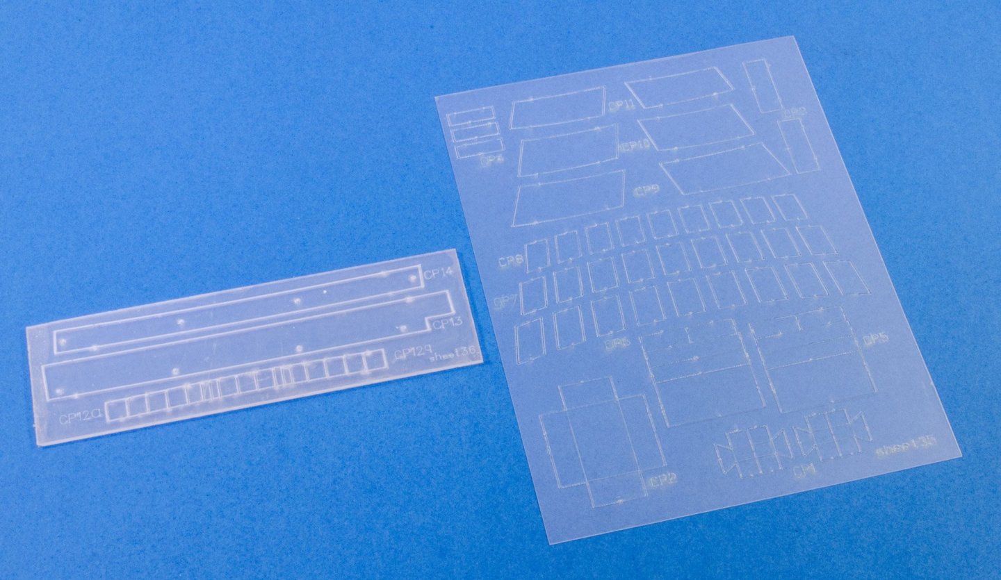
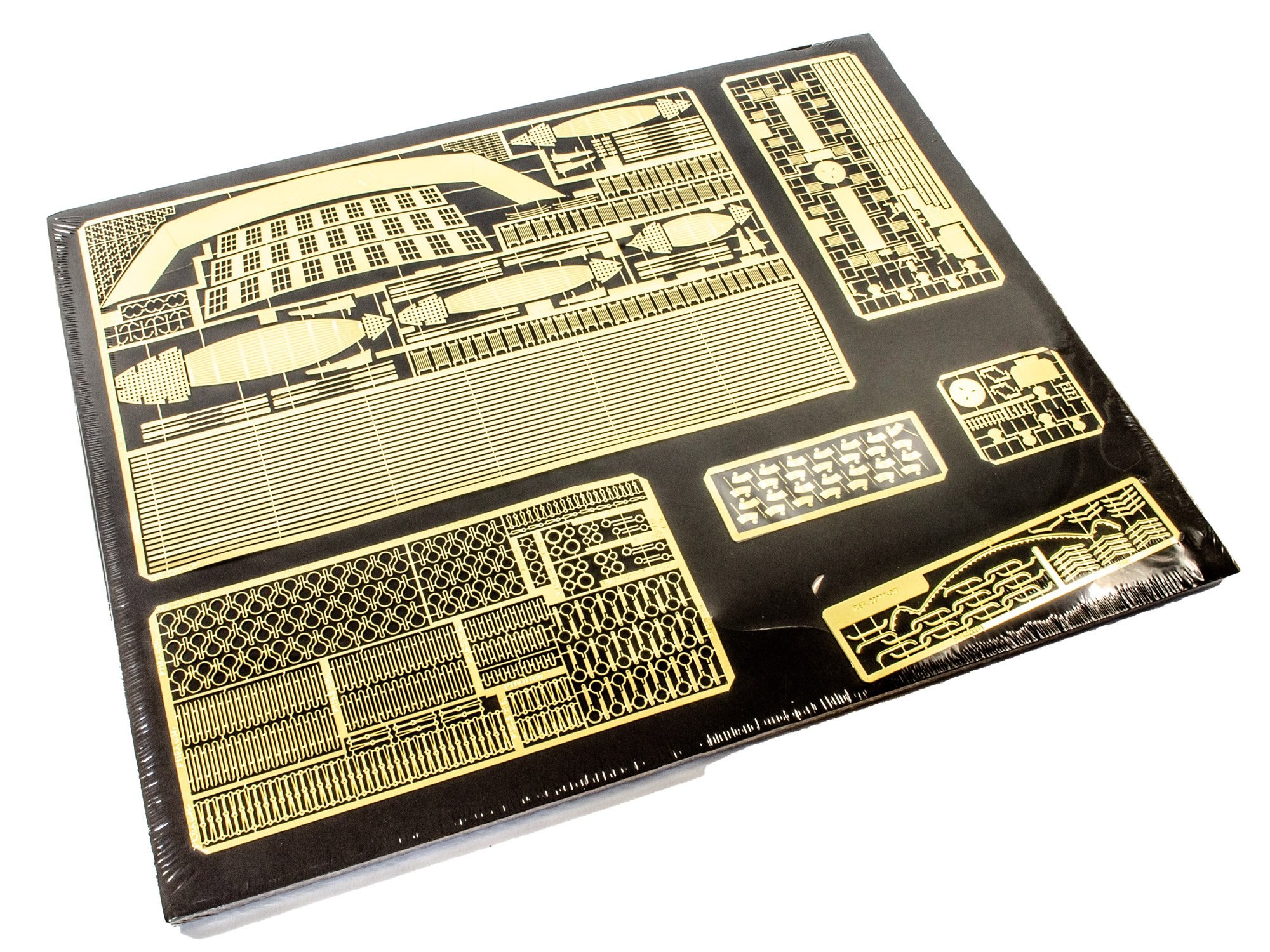
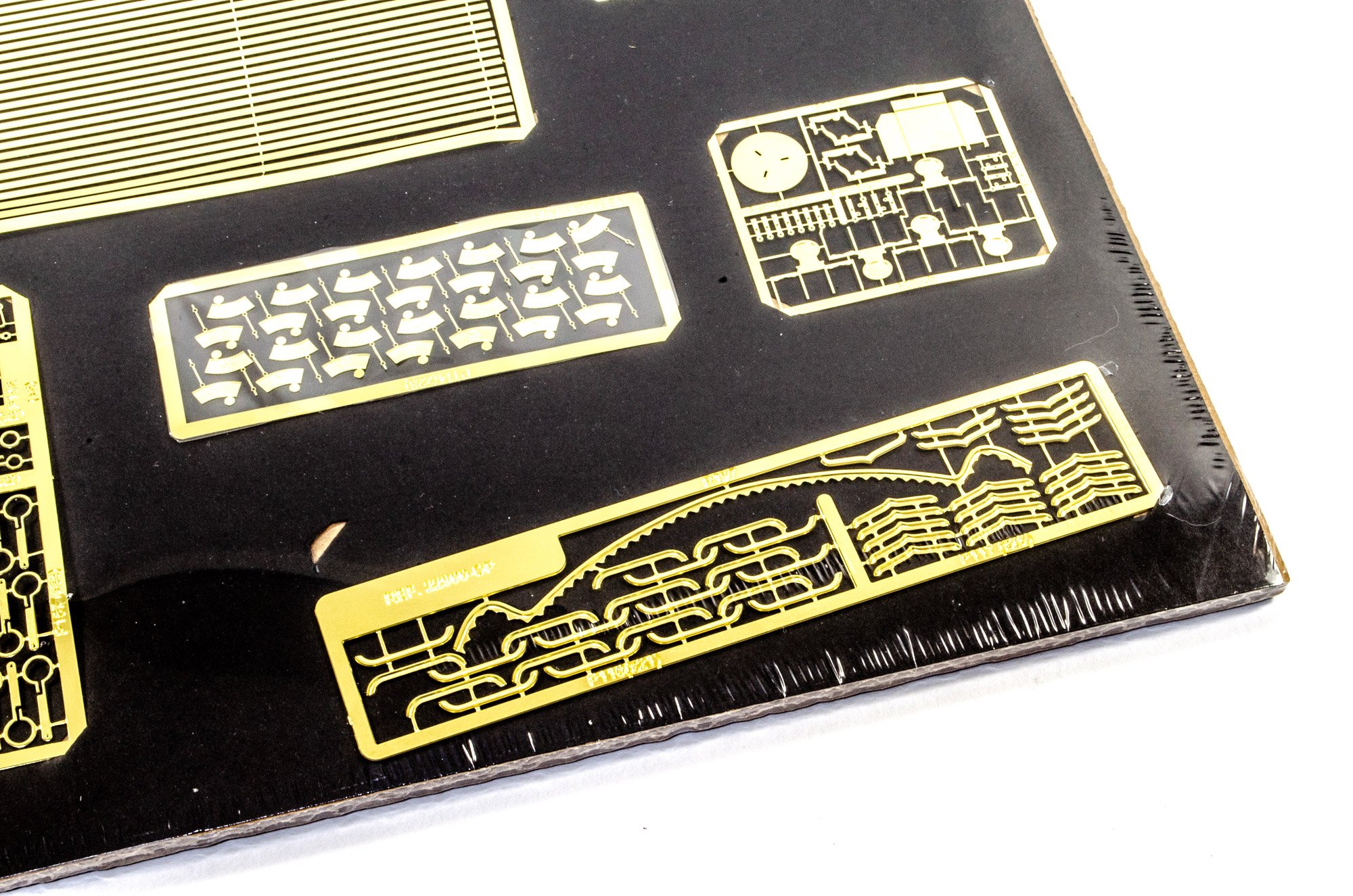
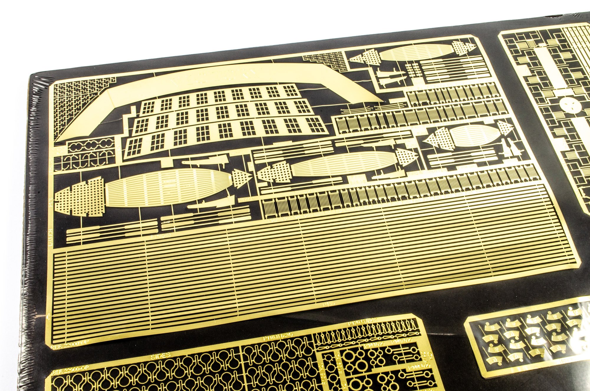
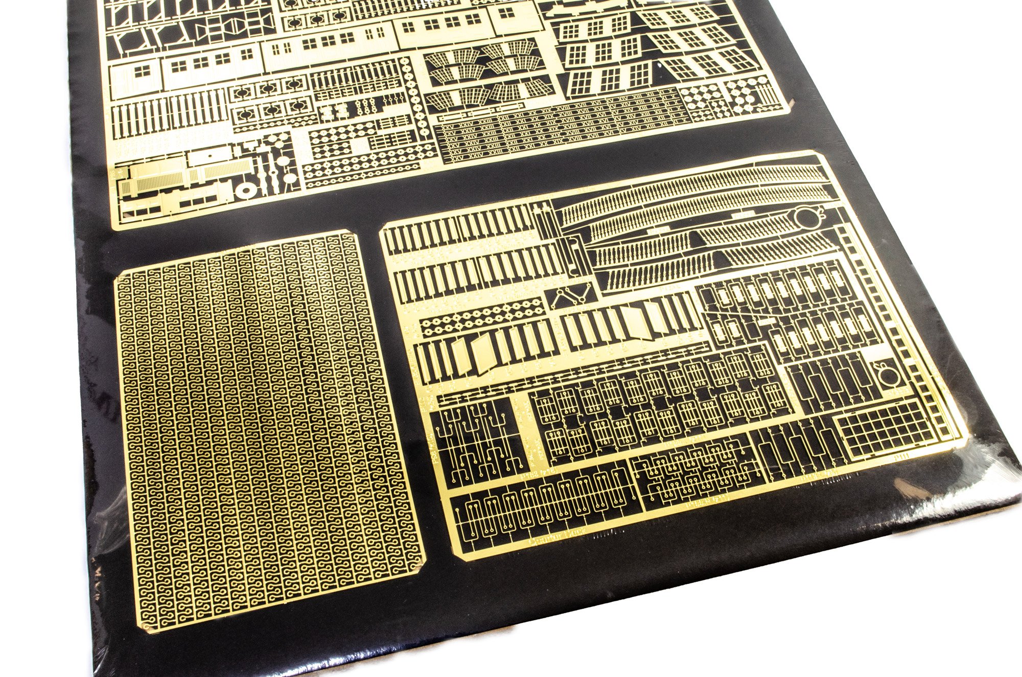
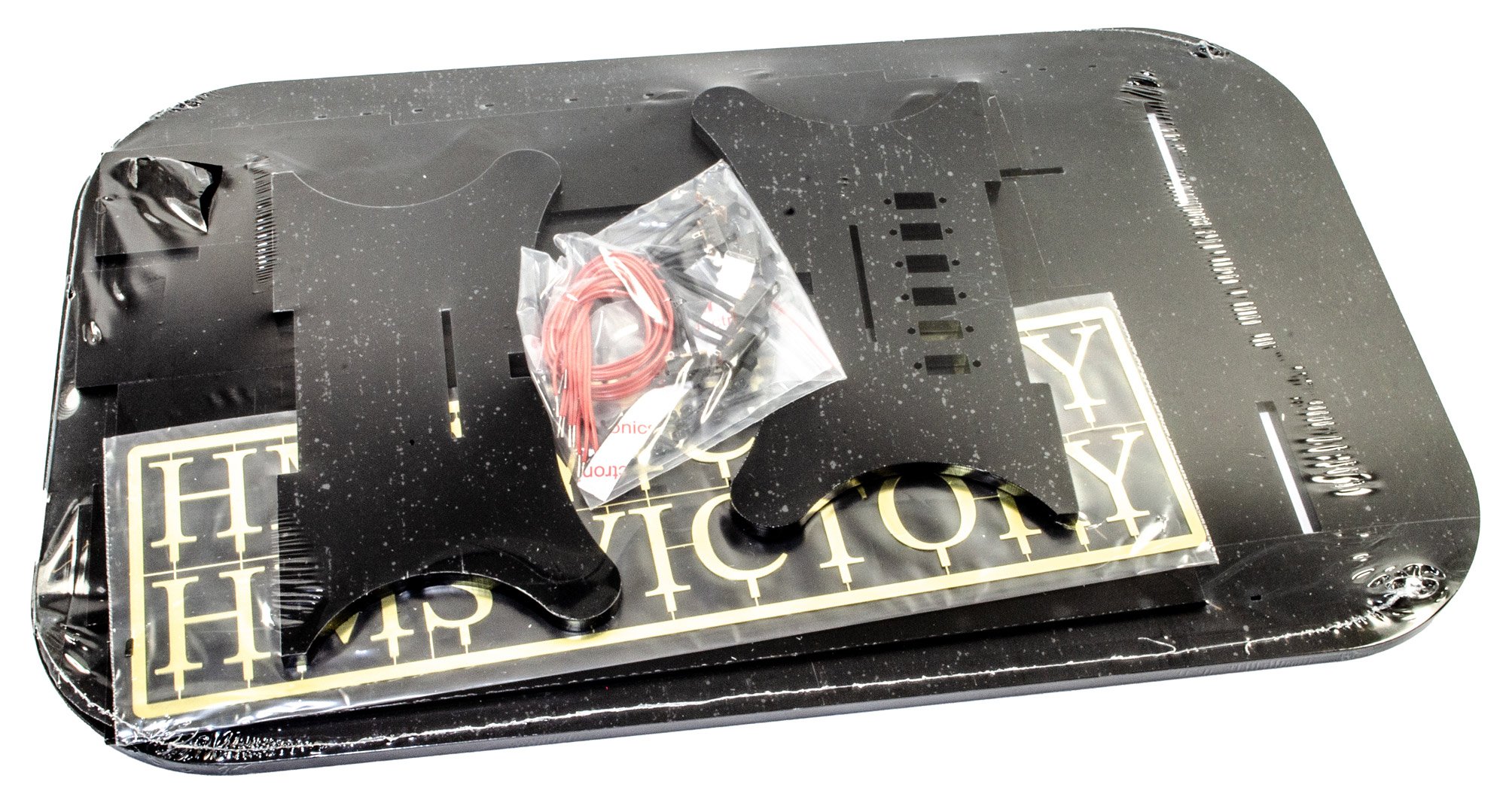
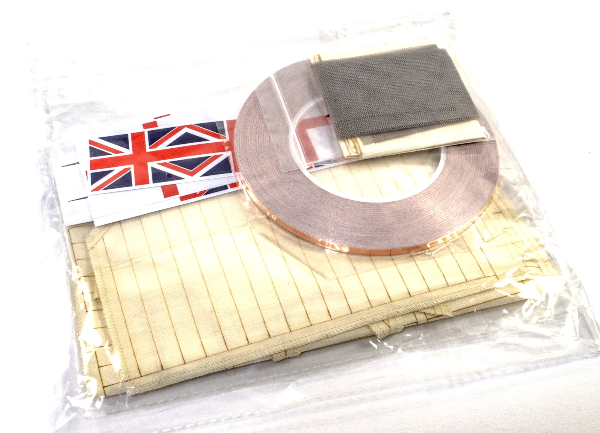
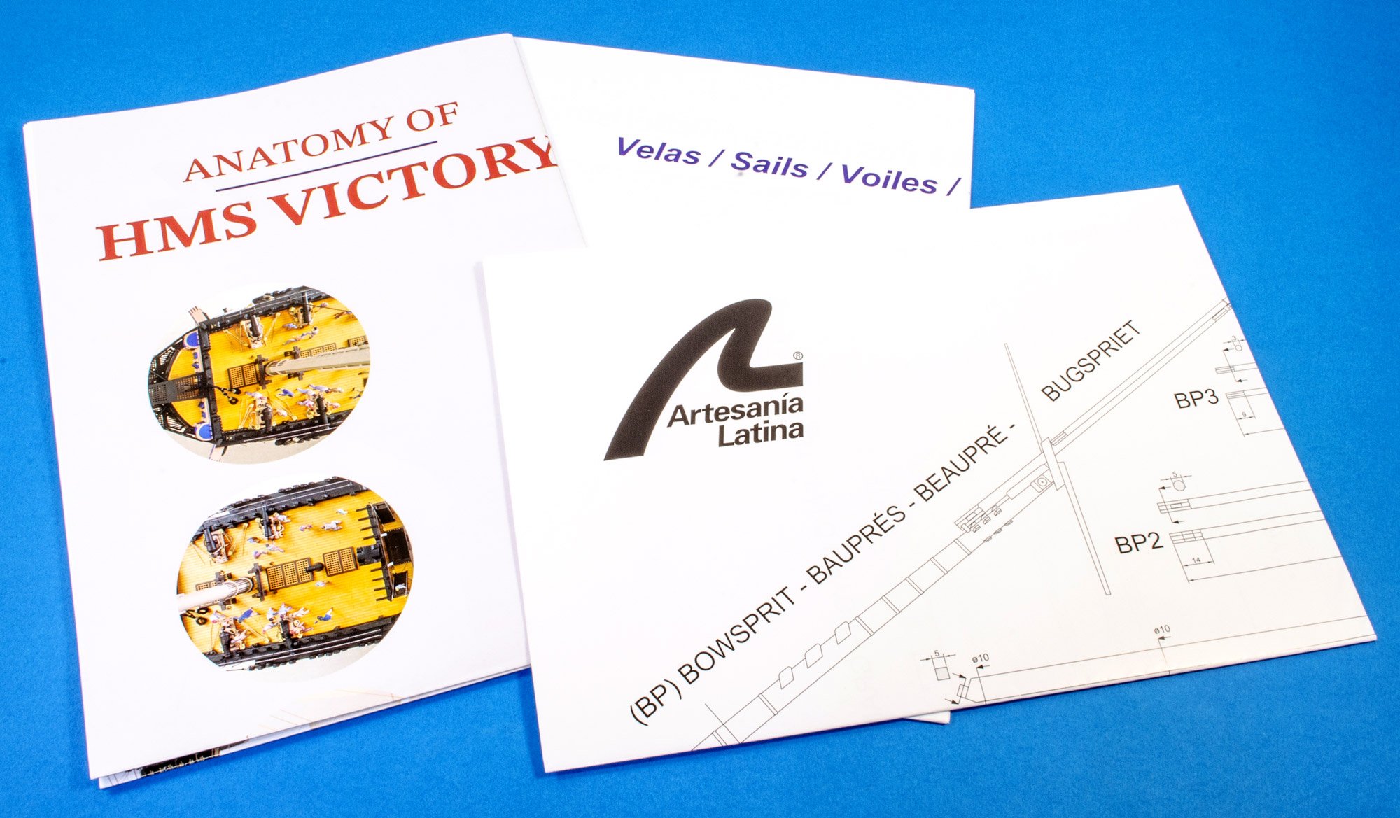
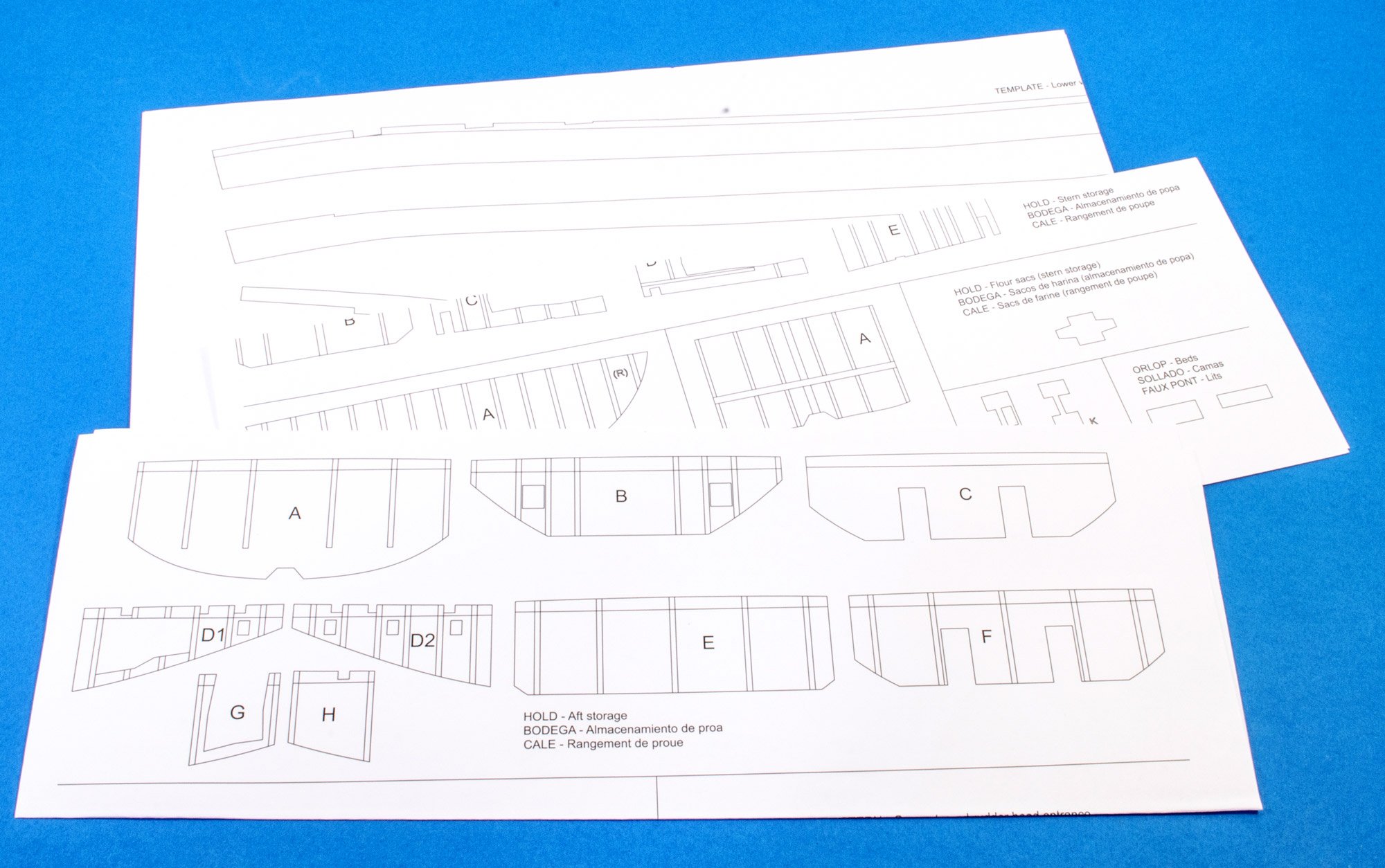
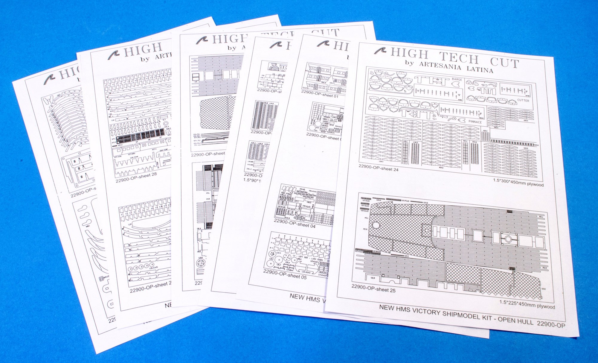
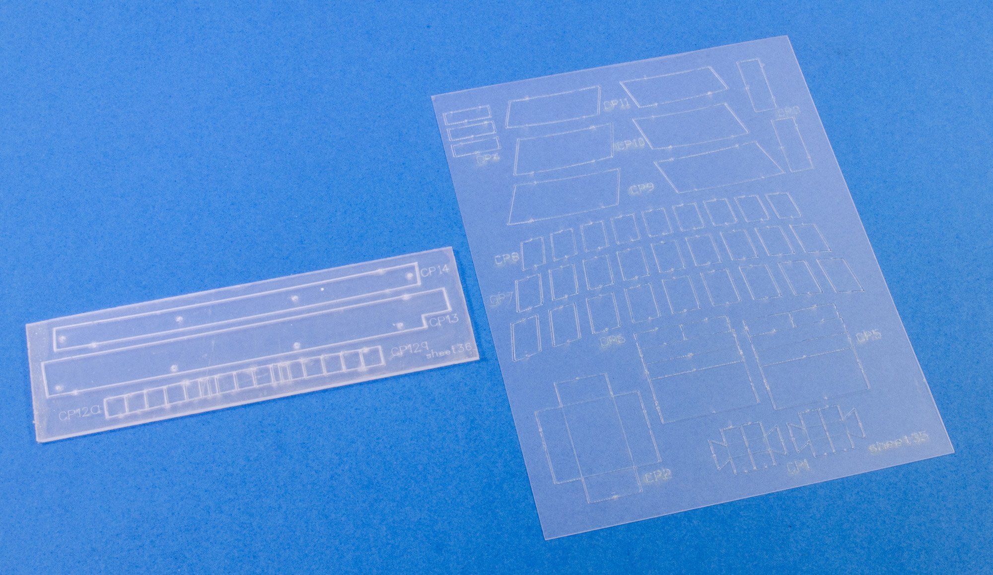
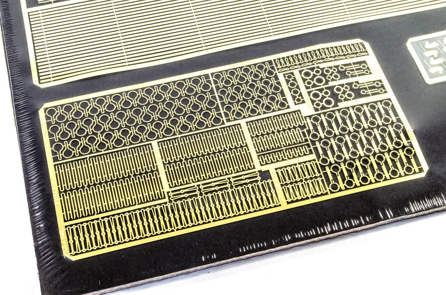
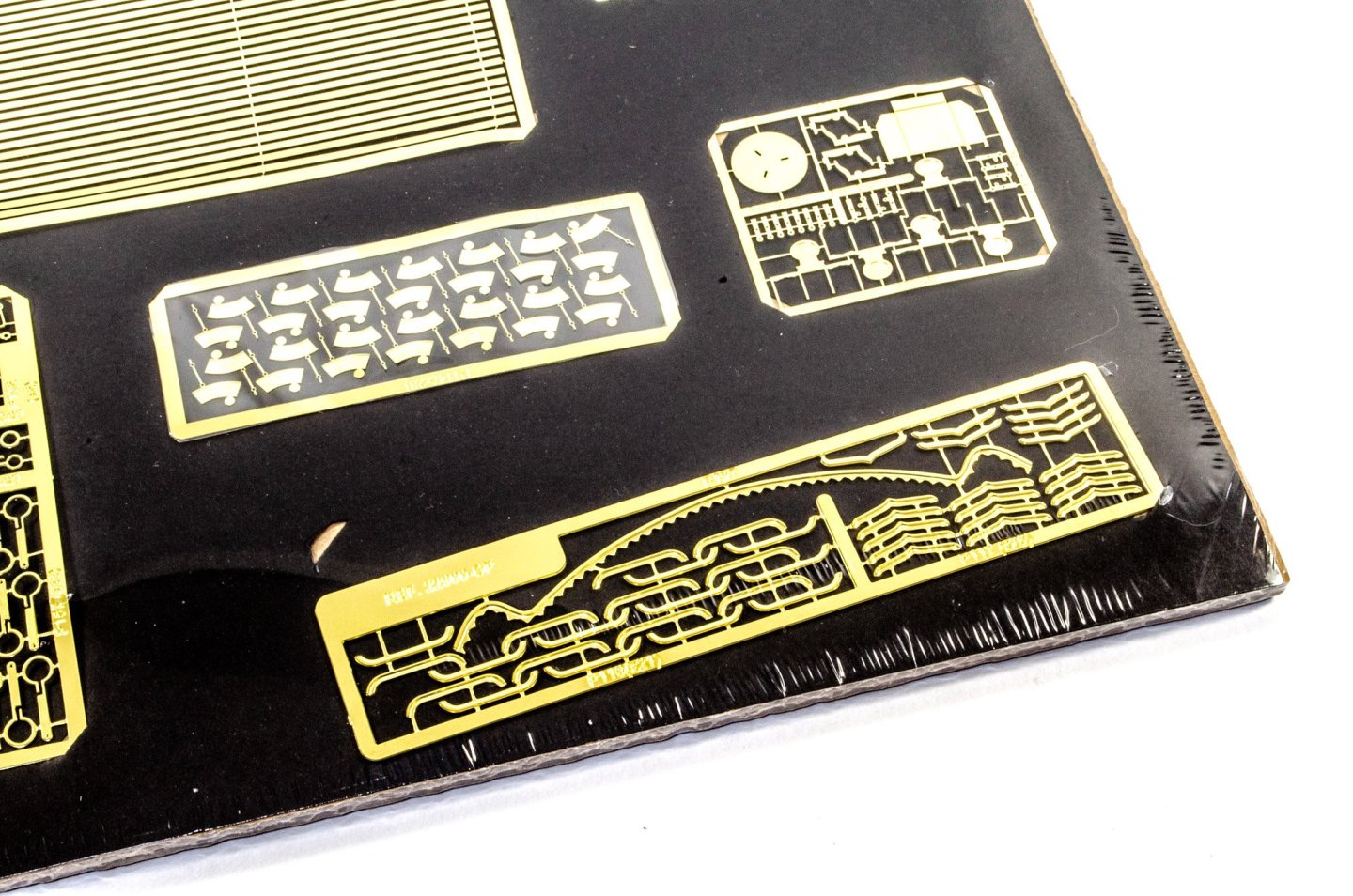
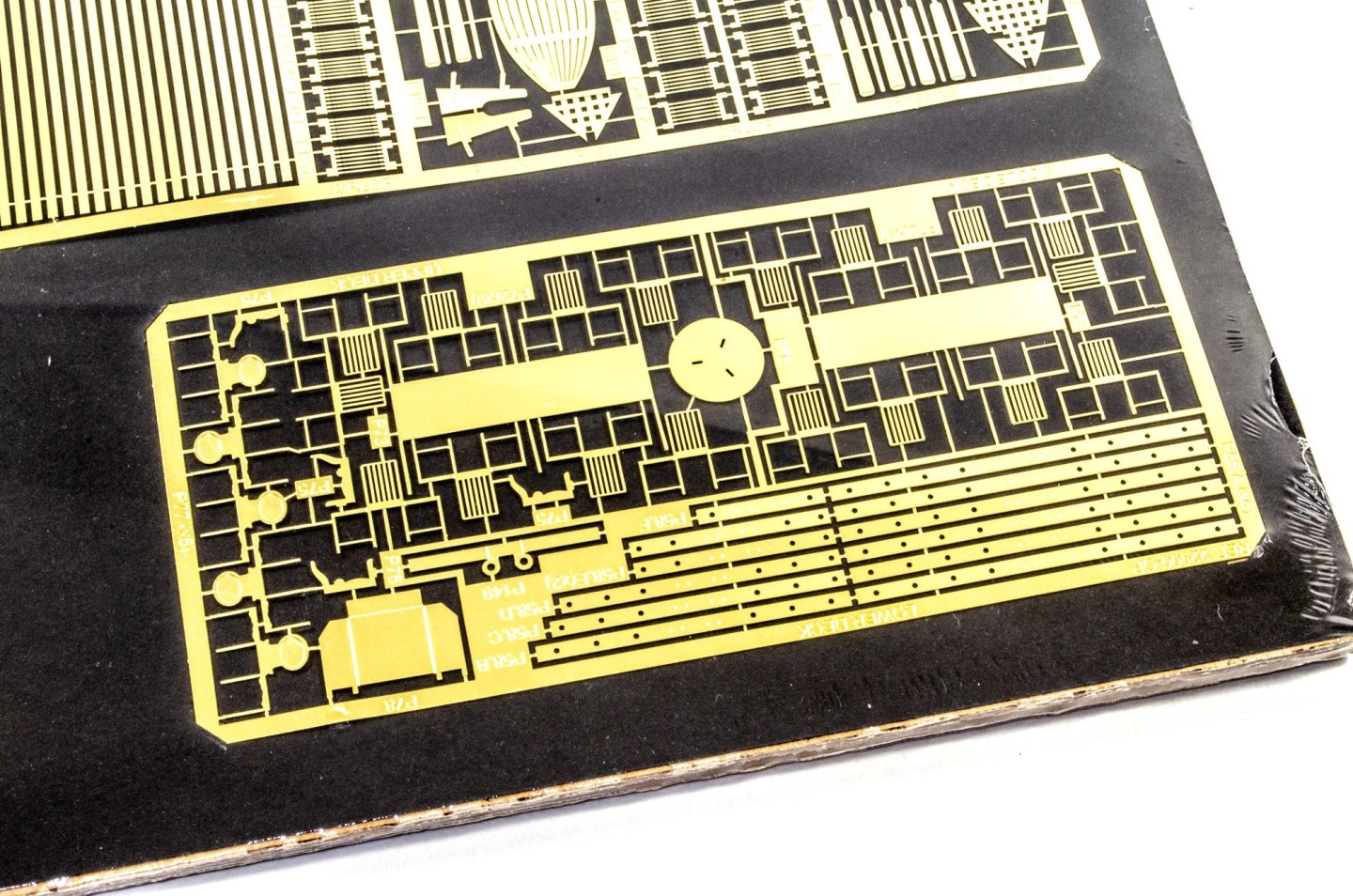
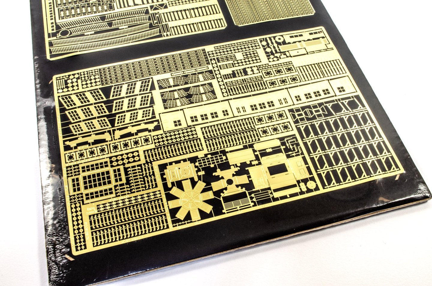
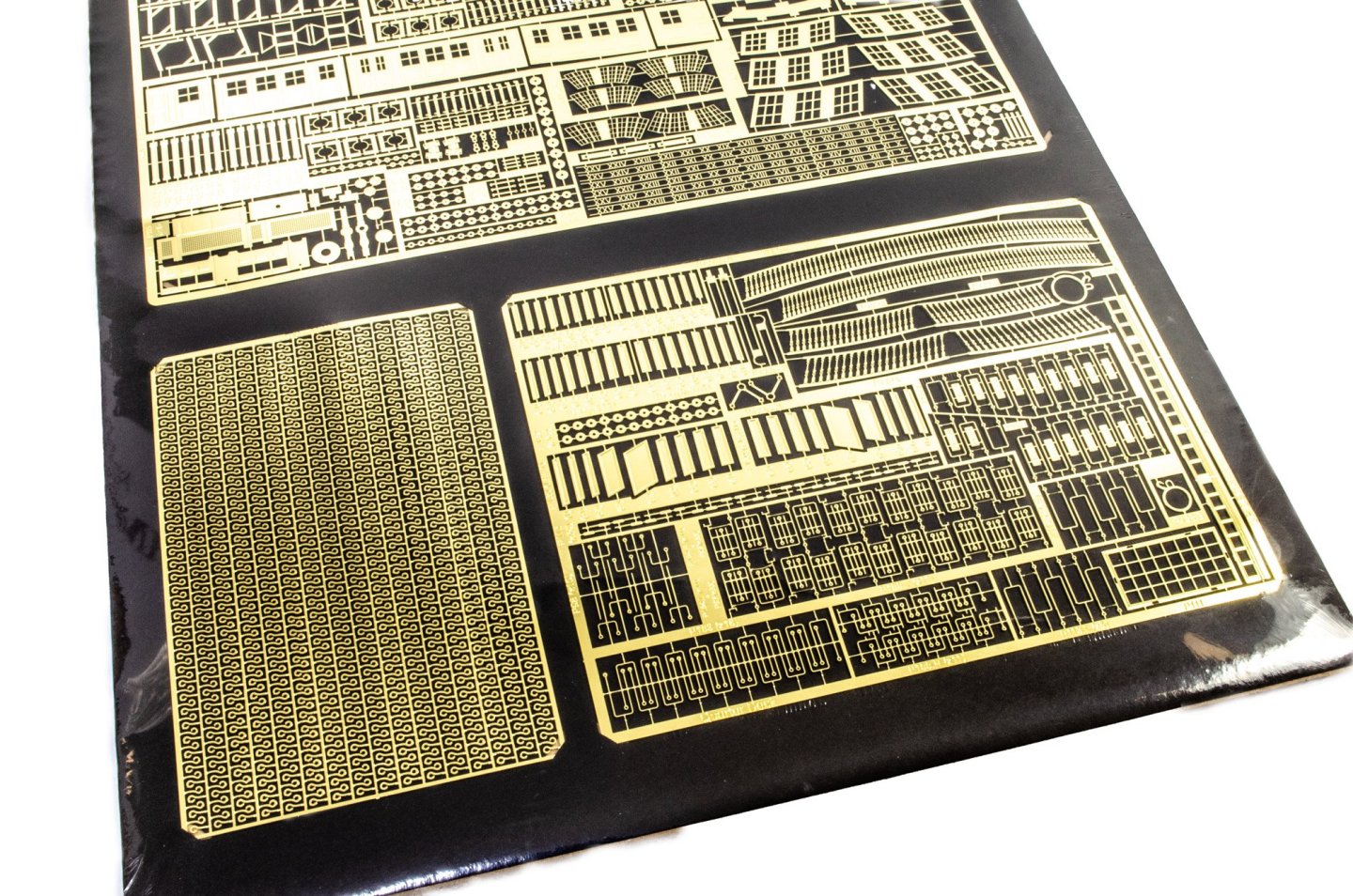
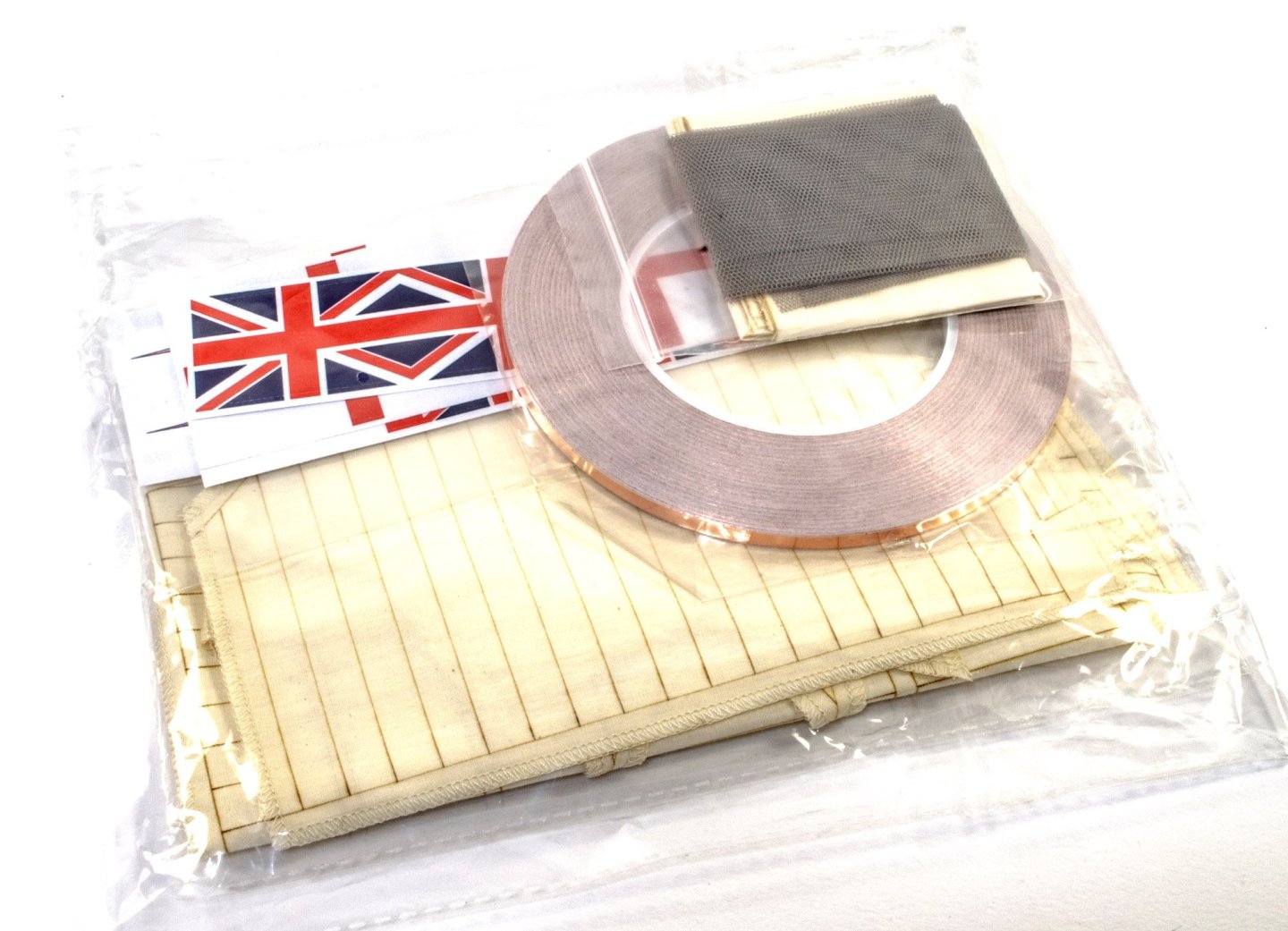
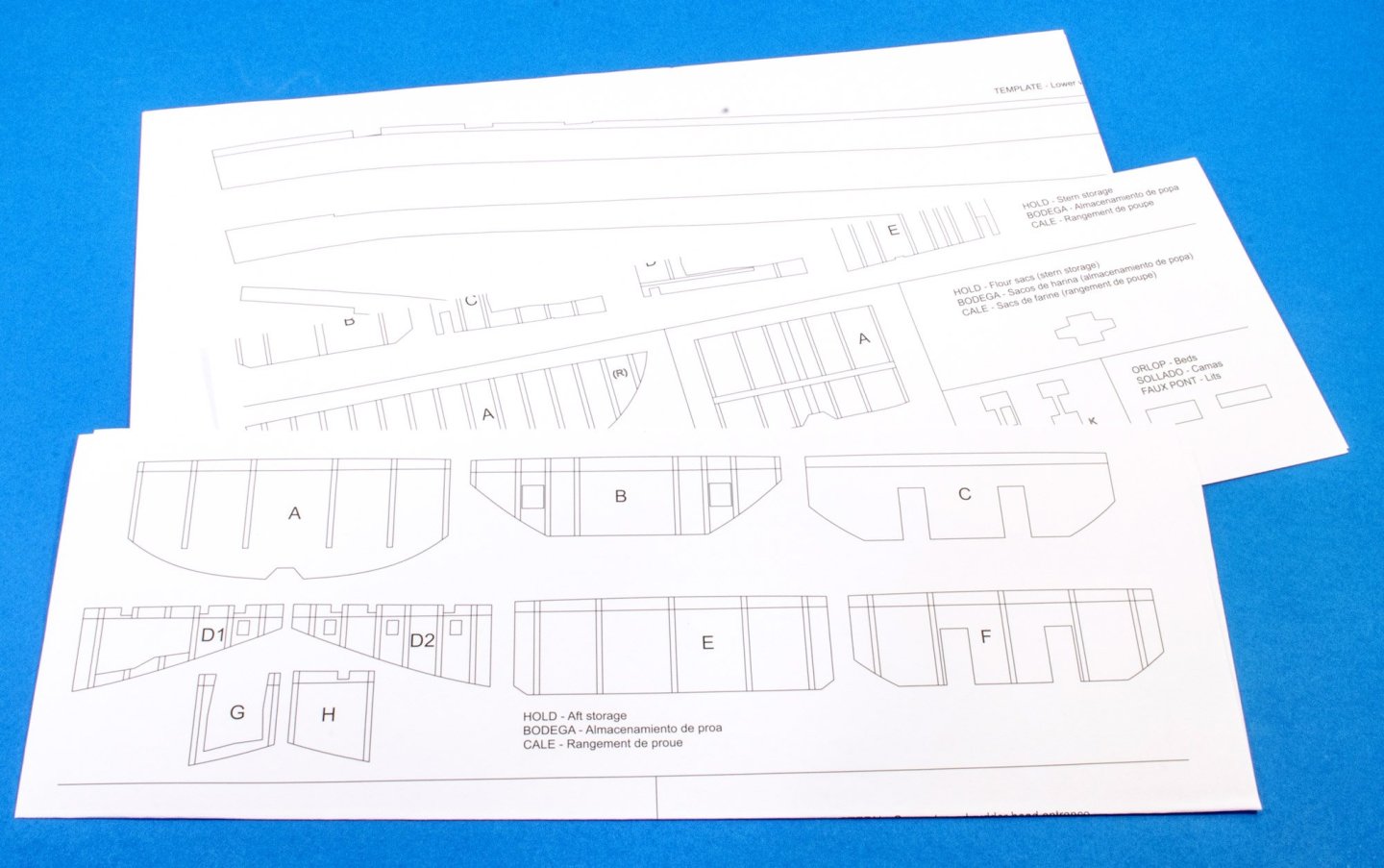
Decoration There are NINE sheets of photo-etch parts....or at first glance there appears to be. One of these looks to be moulded plastic, but plastic in a gold colour. The colour is quite academic though, as all ornamentation would be in the same ochre colour as the hull paint. All sheets are fixed to a large black card sheet, and then wrapped in cellophane to further protect them. A look through these sheets can clearly identify other parts such as those to finish off the ship's boats etc. Also note the strops and chainplates, ship's stove, cabin furniture, quarter gallery sides, lantern bodies, etc. All PE is very nicely etched and is very much of the quality we now normally see on other contemporary kits. Display stand Suppliers usually add some sort of stand, usually in ply. Very few companies offer acetate stands, such as those that VM include. With this kit, Artesania have also opted to include an acrylic stand. This is quite a simple but attractive stand, made from black acrylic sheet, and to be adorned with photo etc lettering which names the ship, so the effect will be in black and gold. Note also some wire and switches, plus cutouts in one stand part so these can be wired. This obviously pertains to the optional lighting set that you can install as you build the kit. This pack contains hammock material as well as copper tape for the hull, flags, and a complete set of pre-cut and sewn sails. Lastly, these are photos of those printed materials I mentioned already, plus a set of parts maps you can see here on the last image. More soon...


-
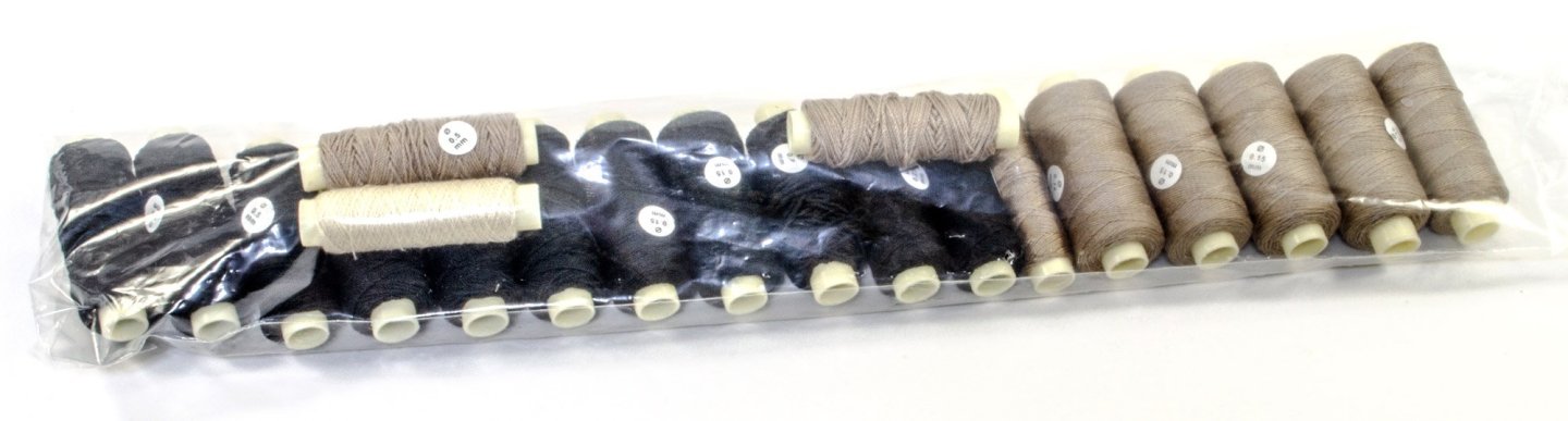
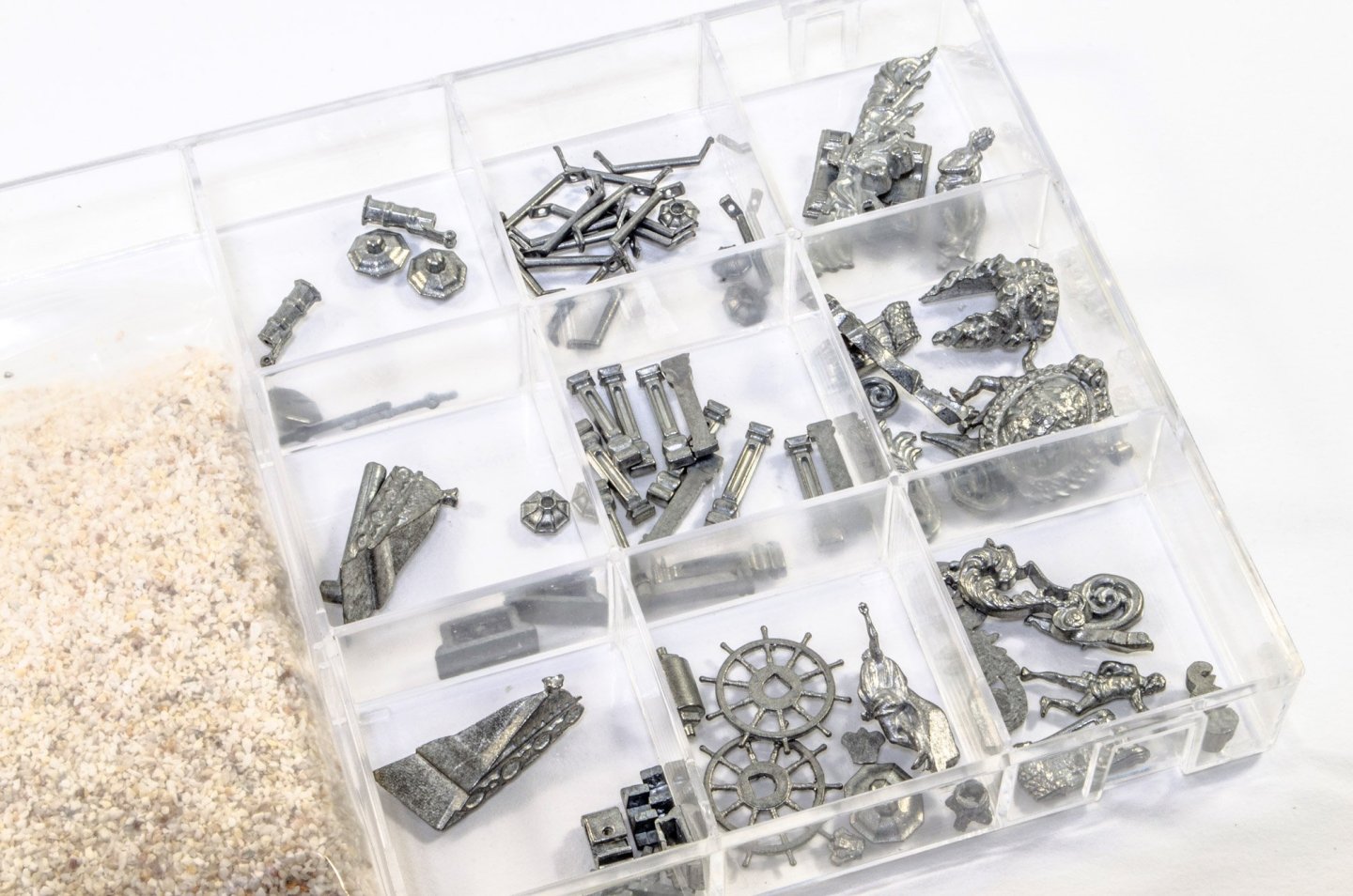
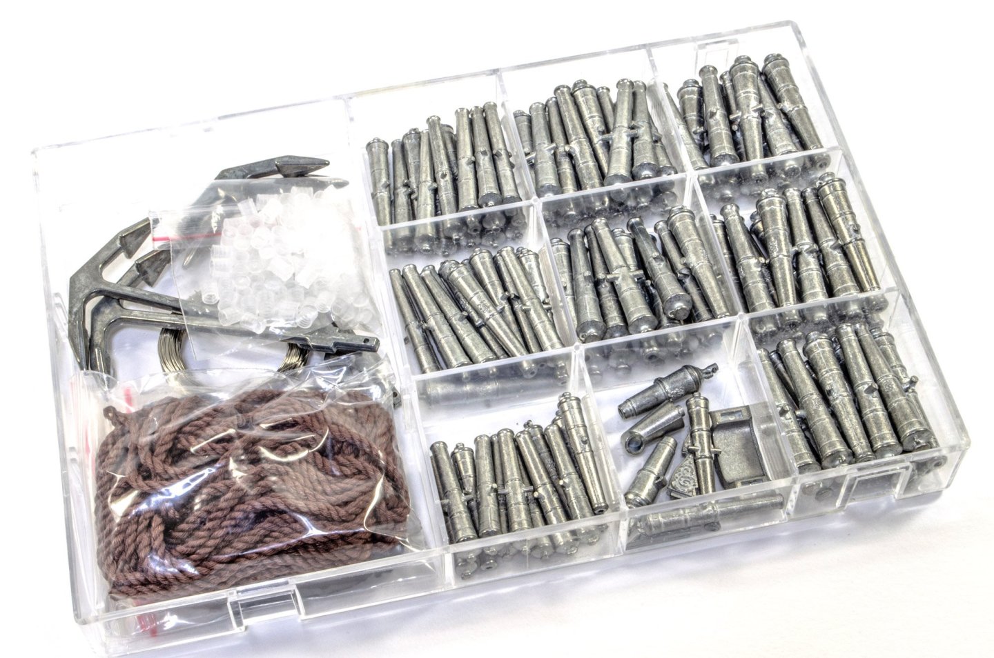
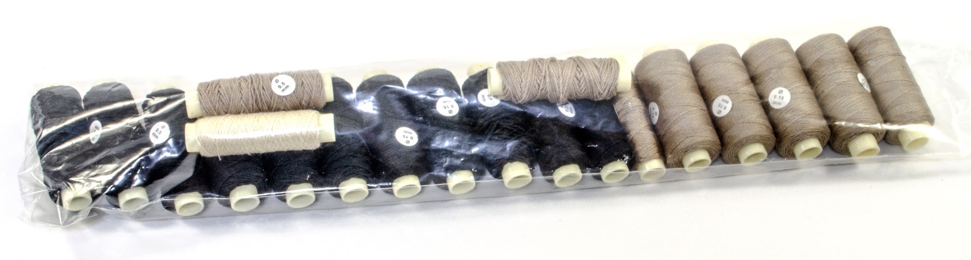
There are FOUR boxes of fittings in this kit release, with one of them in particular being quite heavy. The rigging blocks are quite generic Tamil-type, and there are a hell of a lot, as you'd expect with Victory. A lot of barrels are also included for you to sit around the various decks, to make them look a little busy. Here you see the various pillars and ornamentation for the stern etc. as well as parts for the lanterns. Note also the figurehead crest and other castings that are used for the ship's wheel and the underside of the quarter galleries. The bag on the left is gravel, for the hold. This box contains wire, anchors, hawse rope and cannon. The cannon are very nicely cast with only minimal seam lines to remove, plus they do carry the royal crest too. There is a packet of clear parts here, and these are either the fire buckets or the lantern exteriors. There is another pack of slightly larger, similar parts which would be whatever these parts are not (either lanterns or buckets). Lastly, another box containing rope and various turned and cast parts. There aren't too many brass pins included here, so you will need to pull and re-use them as you go. They aren't aren't very fine, and I would perhaps opt to use those from Amati as you work. This is the other packet of clear parts which do appear to be the lantern covers which you can use to sheath the optional LED parts you can install across the various deck interiors. These sheets contain parts for Victory's various glazed areas. And now, the rigging pack. This is quite generic rope, but is of very reasonable quality. This could be improved further with a block of wax to kill any potential fuzz that this can entail. More soon.