


James H
-
Posts
6,135 -
Joined
-
Last visited
Content Type
Profiles
Forums
Gallery
Events
Everything posted by James H
-

1:8 1965 Shelby Cobra 427 S/C - Agora Models
James H replied to James H's topic in Non-ship/categorised builds
STAGE 25: LEFT AND RIGHT FLOOR PANELS Before any work starts here, it's a good idea to use a bit of tape to hold the battery box line down on the part. I saw this on a build on the Agora forum, and it's a great idea! The two floor panels are now screwed to the chassis with 4 screws each. The fit is perfect. And now the good bit...the engine is installed! Just two screws for this. I also took the opportunity to tidy up the cables a little as I left it a real mess last time. -
1:8 1965 Shelby Cobra 427 S/C - Agora Models
James H replied to James H's topic in Non-ship/categorised builds
Pack 4 STAGE 24: BRAKE PARTS FOR THE FRONT RIGHT WHEEL In this stage, we simply build the brake unit for there front wheel. To start with, the spinner and hubcap are first pushed together. No glue needed here. The wheel hub now inserts through the brake disc so that it freely rotates. The brake calliper then screws to the wheel hub whilst entrapping the brake disc. The brake unit can now be fitted to the right wheel. This will only go in one way, and then a screw from the outside holds the two together. The spinner/hubcap them sits over the screw using its magnet. -
Hello JB Daykin, Welcome to Model Ship World™. Please feel free to browse around and get to know the others. If you have any questions please don't hesitate to ask. JB Daykin joined on the 02/02/2021. View Member
-
Hello Stickman, Welcome to Model Ship World™. Please feel free to browse around and get to know the others. If you have any questions please don't hesitate to ask. Stickman joined on the 02/02/2021. View Member
-
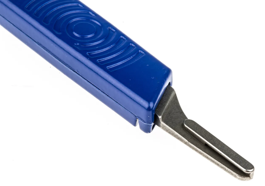
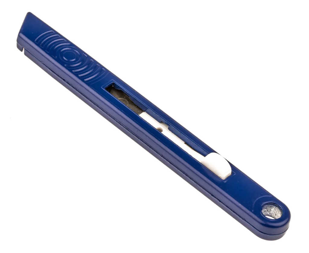
I've been using Swann Morton scalpels to cut timber for models for 20yrs, and for plastic/resin for almost 40yrs...BUT I sometimes use the No.10a for heavier work as they are less likely to break. However, I rarely get an SM No.11/15 blade break on me. I've probably had a couple break last year, so not many, and I use a lot of these.
-
Agreed.
-
I've used Swann Morton scalpels since I was about 12yrs old, so I'm very used to them. A few years ago, I switched to their retractable handles which hold the same blades. For blades, I use 10a, 11 and 15 (the latter are small curved blades which are great for awkward cuts and scraping). https://uk.rs-online.com/web/p/scalpels-craft-knives/8477580/
-
@DaveBaxt it's still shown on their website: https://www.hobbyzone.pl/en/3-boat-building-tools/ but temporarily unavailable. Might be worth emailing them direct.
-
It's half size, so around 3ft tall when complete, plus the base it stands on. Quite a size! (also seriously heavy too)
-
It's a real nice build. I know it's only a bolt/screw together job (with some CA in places), but it sure gives me something to do in between planking tasks etc. 🤣
-
STAGE 90: FITTING PARTS TO THE LEFT THIGH As it stands the thigh has no fascia, so this part supplies that. Three screws are used to fit it, screwed from the inside leg so they aren't seen. The piston is now fitted into position. He's certainly looking VERY impressive!
- 53 replies
-
- 10
-

-
STAGE 89: FINISHING THE LEFT HIP JOINT AND ASSEMBLING A LEG PART The muscle piston simply pushes together. Th ship outer cap can now be pushed into position and an Allen key used to tighten the joint. Again, this can be slackened later to pose the limb.
-
STAGE 88: ASSEMBLING THE LEFT HIP JOINT As with the right hip, the inner joint case is slipped into the hip, followed by the ball joint. On top of that sits the outer plastic joint case. The thigh is sat up to the T-800 so the ball joint engages with the hip. This is then screwed into position. The outer cap is then screwed into place with four screws. At this stage the hip will STILL be loose. This is normal.
-
STAGE 87: FITTING A JOINT MECHANISM TO THE LEFT THIGH In this stage, the hip joint is assembled and glued to the left thigh. That's it for this stage!
-
STAGE 86: ASSEMBLE THE SHOULDER, AFFIX THE LEFT ARM TO THE BODY A hip joint is included here, but that is reserved for the next stage. Fitting the arm to the body is very simple. The arm slots into position and a ratchet disc is glued into the shoulder joint connector. An Allen key is used to tighten everything up, and this is then used to slacken joints off later to pose the T-800. For now, I'll keep the pose fairly neutral.
-
STAGE 85: EXTEND THE LOWER LEFT ARM, AND CONNECT IT TO THE HAND To connect the hand to the forearm, pistons are needed for the forearm shafts. These will engage the ball joints on the back of the hand. These are now assembled and fitted as before, and the spring/tendon connectors are added to the hand. Those springs are then connected as per the opposite hand. Arm complete!
-
STAGE 83 & 84: ASSEMBLE THE LEFT FOREFINGER AND THUMB These two stages include the parts for building the thumb and last finger, and these are fitted to the hand. Ball joints for mounting the hand to the forearm, are also now installed.
-
STAGE 82: COMPONENTS FOR UPPER LEFT ARM, FOREARM AND LEFT HAND Fittings are supplied to connect the finger I previously built, to the left hand. We also have another forearm shaft and the cover. This allows me to fit this assembly to the upper arm that was built in the last pack.
-
Pack 9 Here we are on the 75% mark on this build, and you really need space to store this when this pack is complete. The aim of this pack is to construct the complete left arm, hand, and and also a good chunk of the lower left leg. There is an amount of repetition here to the right arm, hand and leg, so as this build will primarily be for a magazine, I've done this pack as an abridged build. STAGE 81: COMPONENTS FOR THE FOREARM AND THIRD FINGER OF THE LEFT HAND The finger for this is assembled in the same way as the others, and still adding the neoprene tube to the joint BEFORE inserting the pin. It really is the only way to work this. Finger joints are all nice and stiff, with no floppiness. The forearm shafts are also assembled to the arm as they were on the right hand side.
-
Nope! Zero politics. 🤫
-
I thought you were from Wickford, UK? That's an idea!
-
This is just incredible. I so want to do this with mine when the time comes.
.thumb.jpg.f9cf4ba7a148e91bc456ec282964a6f2.jpg)