James H
-
Posts
6,134 -
Joined
-
Last visited
Content Type
Profiles
Forums
Gallery
Events
Everything posted by James H
-

1:8 1965 Shelby Cobra 427 S/C - Agora Models
James H replied to James H's topic in Non-ship/categorised builds
Onwards with Pack 7! It really doesn't seem to have taken long to get to this stage. Quite a simple pack this month that concentrates on the interior, so we can 't yet cure the wobbly front wheels on the main chassis. 😜 I've put some stages of this pack in the same sequence as at least 3 stages contain zero work. STAGE 49 & 50: BUCKET SEAT/PASSENGER SEAT COVER, SEAT BELTS AND SEAT-BELT HARNESS First up, the double-sided 3M tape is cut to size and stuck in position on the plastic seat, like this. I ignored the instruction to cut to 4 lengths the same size as you really need to cut them to the actual size needed. The front tape lengths are then trimmed to shape. After peeing off the outer tape paper, the seat cover is slid over the plastic seat and then the sides pulled in so the tape fixes them in position. This is a little awkward, but works quite well. With the seat cover in place, the seat cushion from a previous pack is then screwed to this, holding everything in place. The lap belts are now pushed onto the lugs on the seat underside. These hold the parts real well, and I found no need to add any glue. STAGE 51: BATTERIES, BATTERY CABLES & CUT-OFF SWITCH Both batteries are plugged onto the mounting unit. These can only fit one way. Two screws hold them in position. The battery unit is then screwed into position from the underside using 4 screws. Both battery cables are then connected to the power shut off device, and this is then secured to the interior. Both batteries are then 'wired up' like this. One cable will flap around, but that seems to be normal and it will be hidden behind a seat. Note I removed the gear stick too. That's to stop me damaging it. I'll replace it later in the build. The battery holder is now pushed into place. No screws required. -
3ft tall (half scale) and weighs about 13lbs
-
STAGE 96: ADD THE LEFT KNEE CAP AND ASSEMBLE A TOE The two kneecap parts are glued together and then the part glued to the leg. And the construction of the toes also begins. STAGE 97: BUILD PART OF THE LOWER LEG, AND A SECOND TOE The lower led is now started, and another toe built. STAGE 98: CONSTRUCT THE THIRD TOE, AND EXPAND THE LOWER LEG ASSEMBLY More work on the lower leg with the attachment of muscle pistons, and another toe is born. STAGE 99: BUILD A FOURTH FOOT PART AND ASSEMBLE THE LOWER LEFT LEG The outer shin is now attached to the lower led....and another toe in the series is built. STAGE 100: ASSEMBLE THE LEFT FOOT AND ATTACH THE LOWER LEFT LEG After building the last toe, then can all be fitted to the foot. It's vital to check the toe orientation and position from the instructions or it'll just look weird. I know as I did it upside down the first time. First, the lower toe joints are secured to the lowest point on the front of the foot, then the upper rods fasten to the connection above this. The lower let is now fastened to the T-800 with a single screw. As there is a ratchet disc on this, it can also be posed at the end. Until Pack 11....that's it. 😃
- 53 replies
-
- 10
-

-
Well, we are now onto Pack 10. At this stage, the model is extremely heavy and not so easy to manoeuvre for photographing! I'm also more wary of just lifting this thing by the chest cage and now grip by the pelvis too so I don't put any unnecessary strain on the model. Everything seen in this pack is just a reproduction of building the previous lower leg and foot, so these pics just show the key assemblies. STAGE 91: ASSEMBLE A MUSCLE FOR THE LEFT THIGH Muscle piston! All glued parts use CA gel. If there was a lot of chrome plate, I first rubbed each joint with some fine abrasive paper to provide a better key for the glue. STAGE 92: KNEE, MUSCLE, AND FOOT: MAKE PROGRESS ON THE LEFT LEG These are the three assemblies built for this stage; knuckle joints for the foot connection, muscle piston, and a knee joint with a ratchet wheel glued into position. It really isn't easy flipping the T-800 over, but it needed doing! The thigh muscles are now screwed into position. STAGE 93: BUILD OUT THE FOOT, AND CONSTRUCT ANOTHER MUSCLE A nice, simple one. Another muscle piston, and screwing the foot section to the previously build foot assembly. STAGE 94: AFFIX THE LEFT THIGH MUSCLE WITH NEWLY-CONSTRUCTED TENDONS The other muscle piston is now fitted to the thigh, then connected to the other muscle and screwed through the thigh frame. The ankle ball joint is now fitted to the foot underside. STAGE 95: ASSEMBLE AND AFFIX A KNEE JOINT If only a knee replacement was so simple! The knee joint is fitted with the ratchet discs and muscle piston. This is then dropped into position and the knee end caps pushed into position and tightened with a hex screw. This can be adjusted to pose the T-800 when complete. ...and a little more work on the foot with the piston connectors and ankle joint.
-
Cheers, that really is a beauty. Now I see her when I visit the site 😁

- 222 replies
-
- 3
-
-
- First Build
- Lady Isabella
- (and 2 more)
-
Just OUTSTANDING!!!! Absolutely love the whole finish from the black hull to the sails you managed to dye far better than I did 😆 Question is....what next? I'd love to see you tackle a Flirt or Duchess. Could you create a Gallery album for your finished pics too?
- 222 replies
-
- 2
-
-
- First Build
- Lady Isabella
- (and 2 more)
-
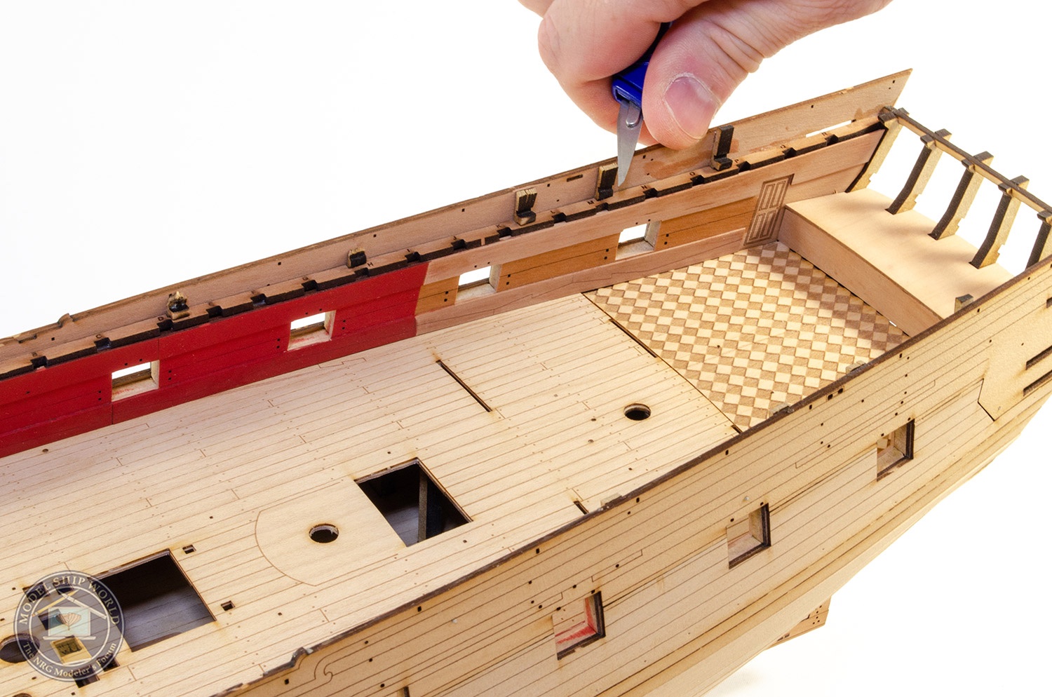
I did a couple of photos last night just showing the various completed deck fittings sat in position on the deck. There are a couple of assemblies I've incorrectly positioned, but everything will be ok when she's done. About one month since work began.


- 355 replies
-
- 43
-
-
- vanguard models
- Sphinx
- (and 1 more)
-
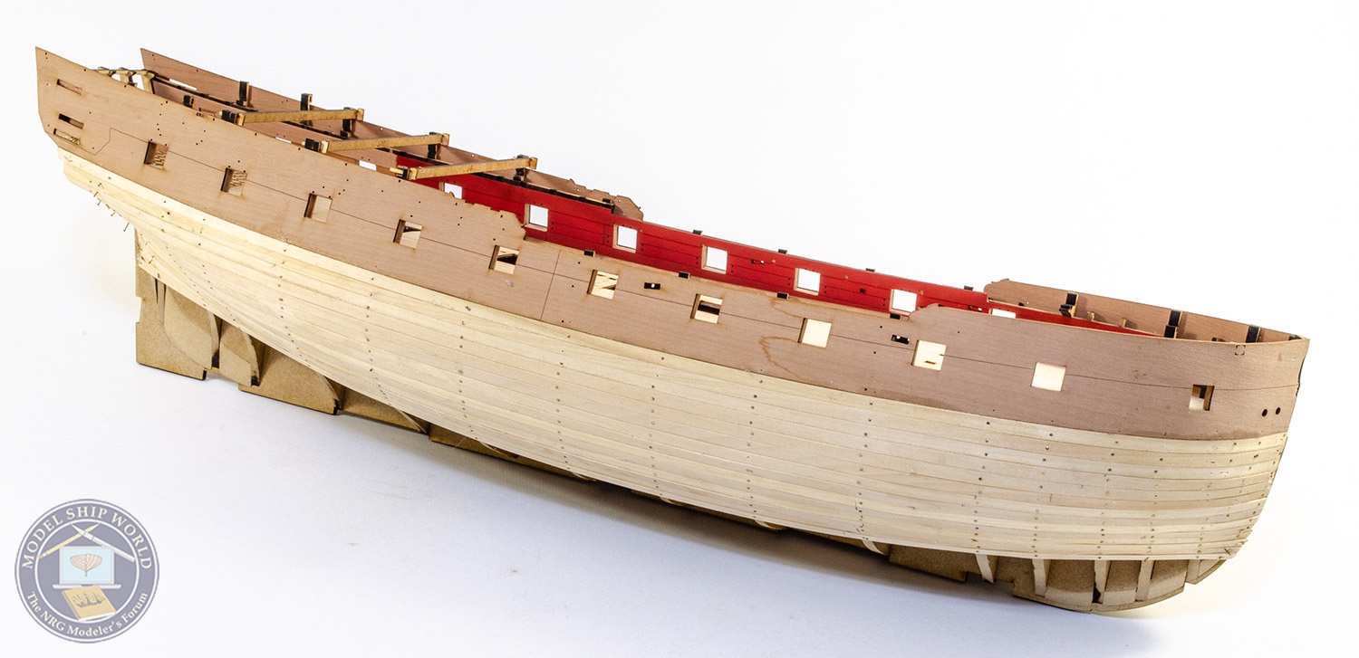
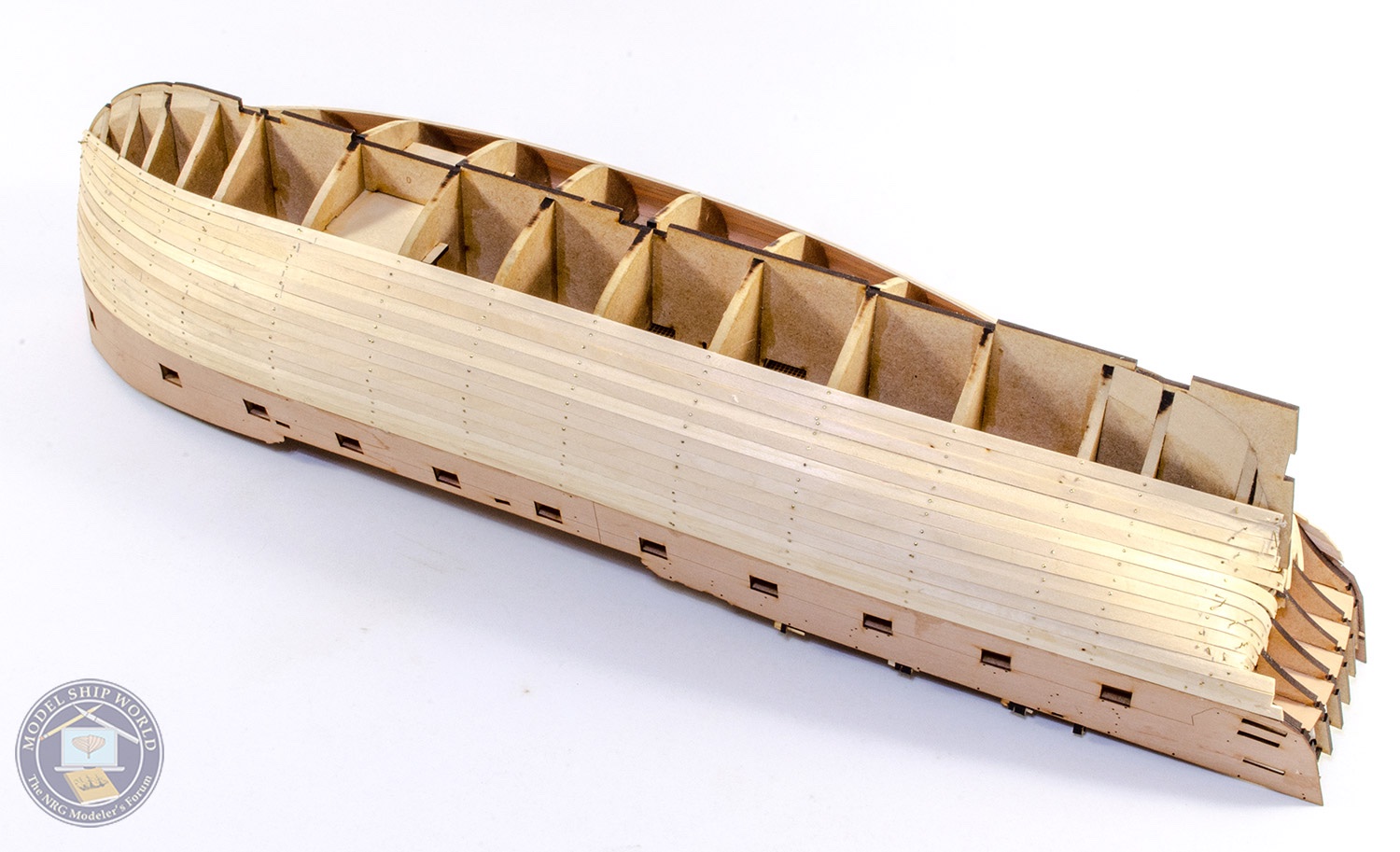
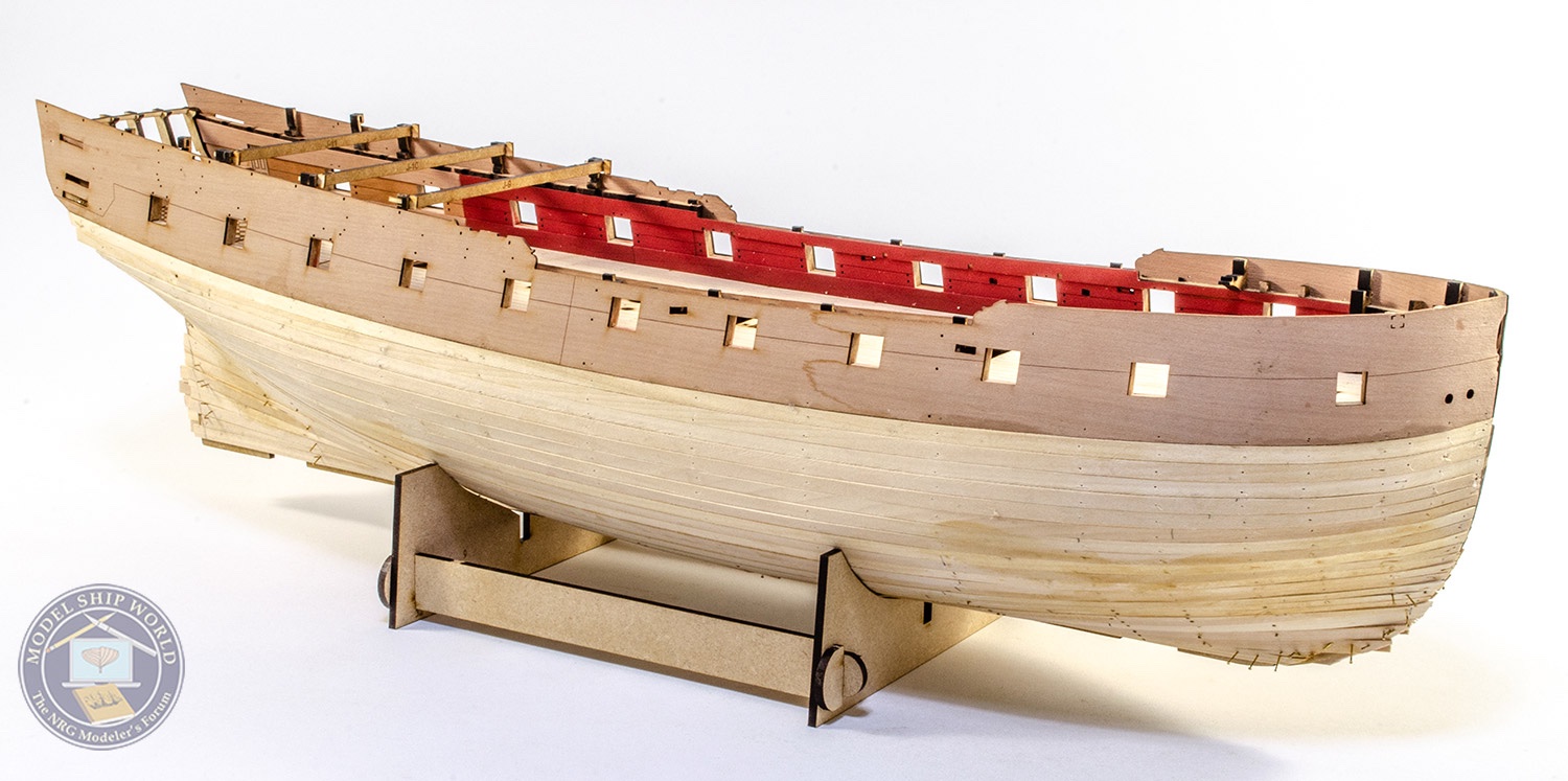
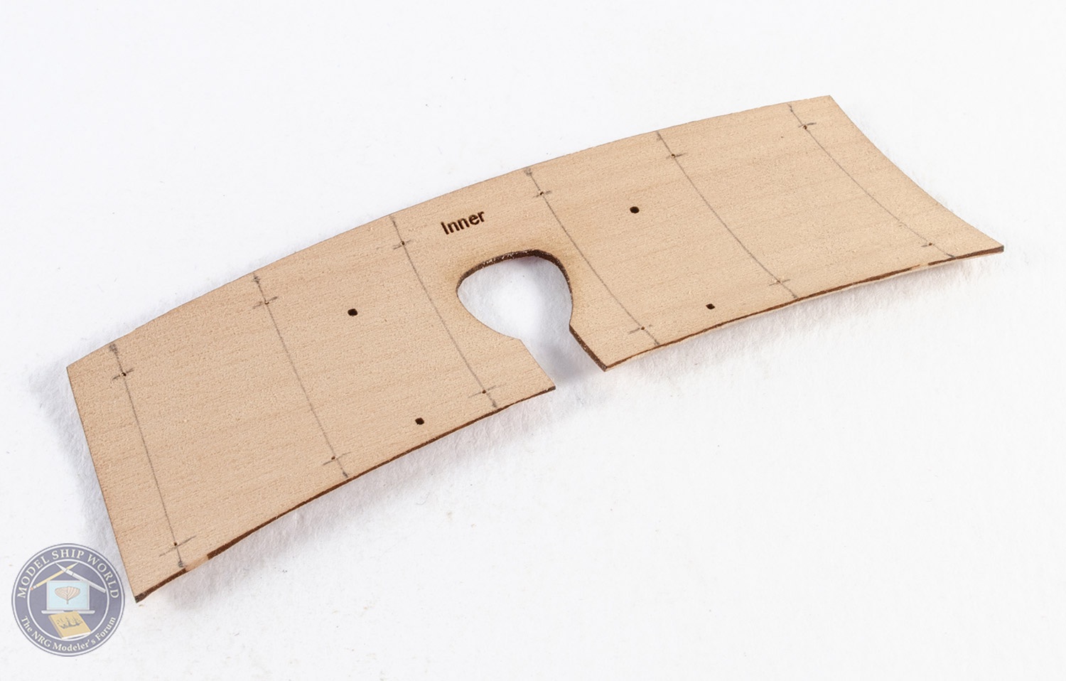
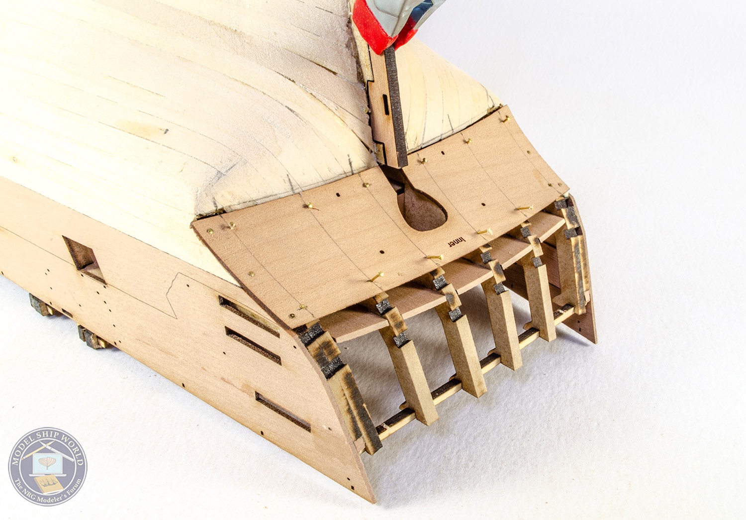
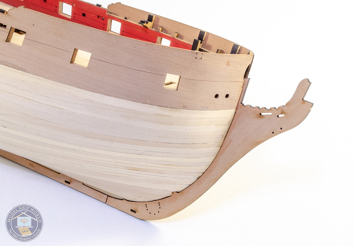
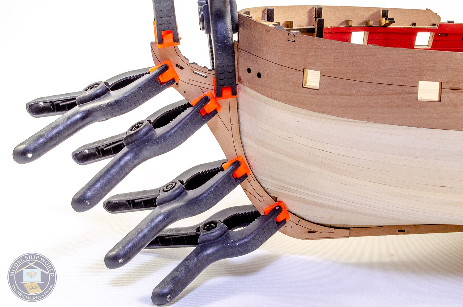
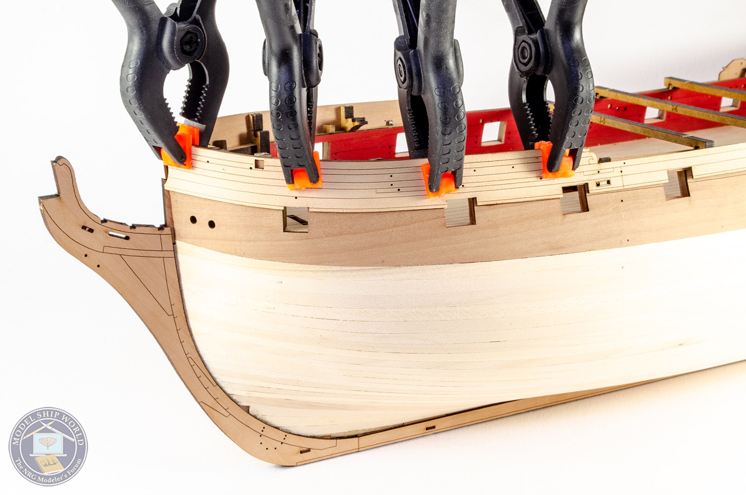
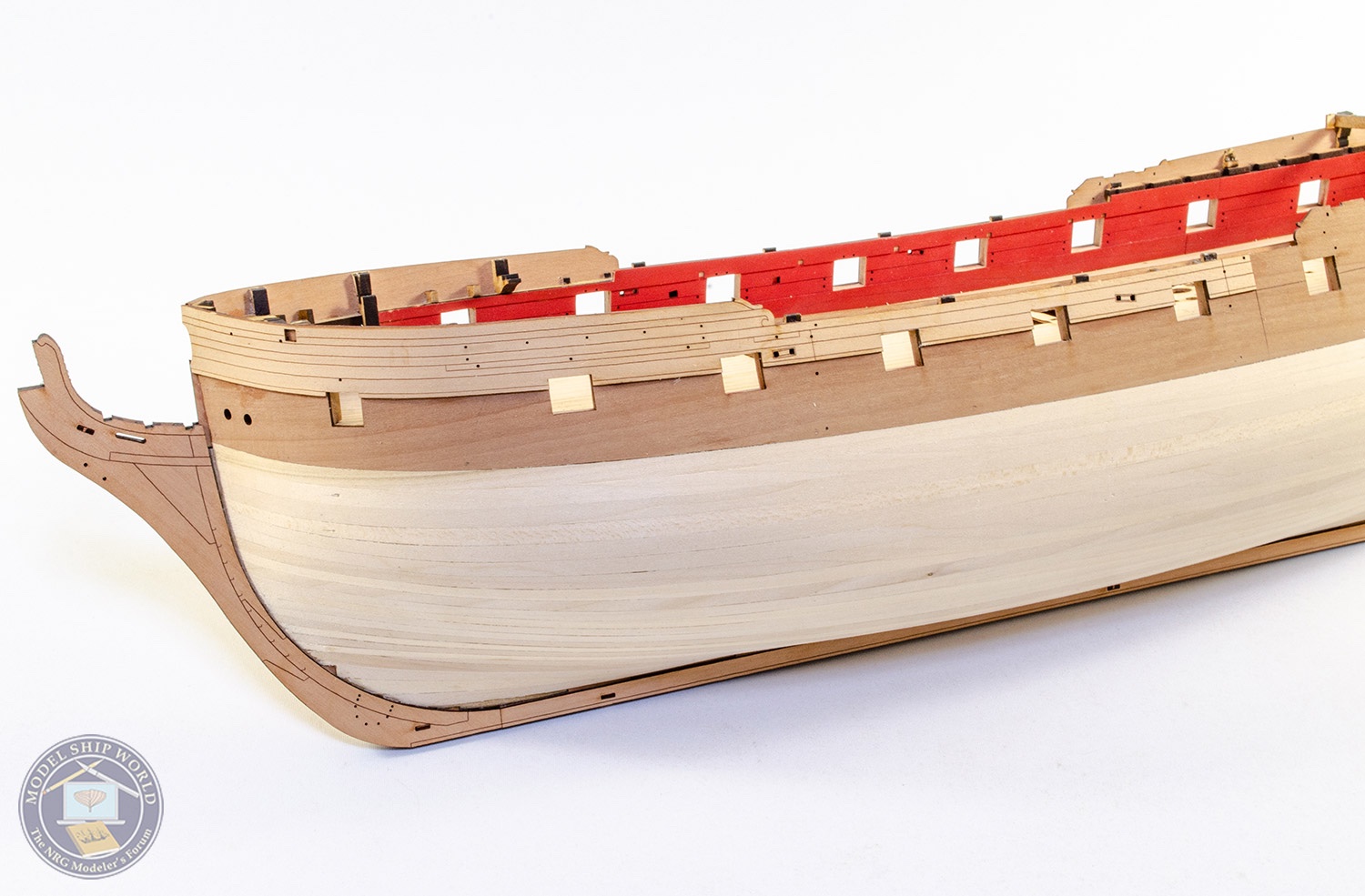
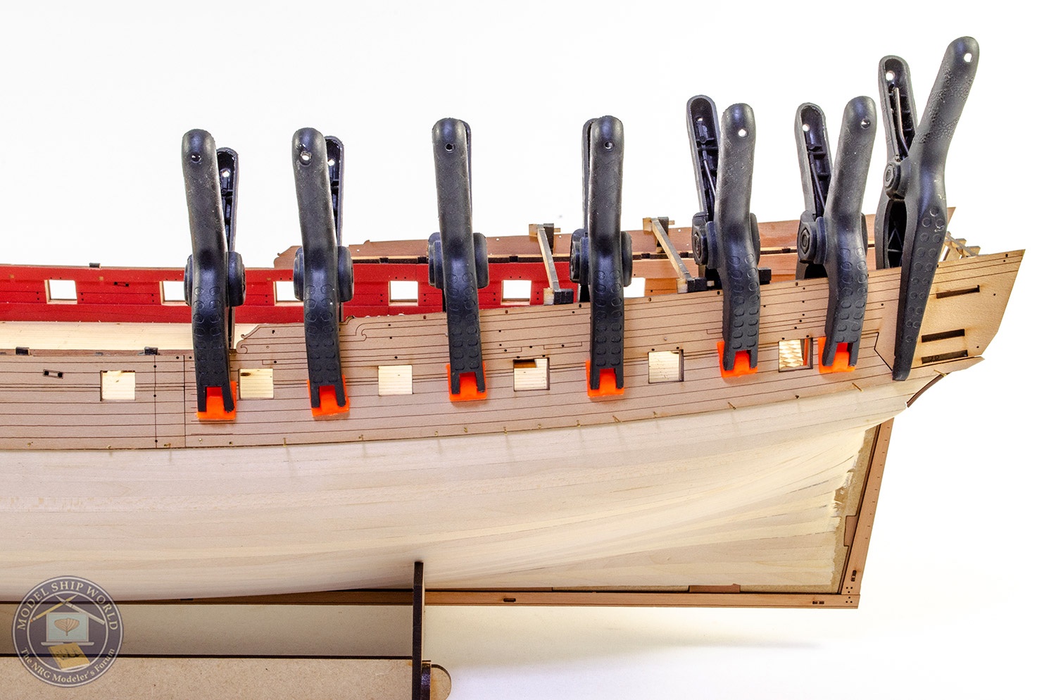
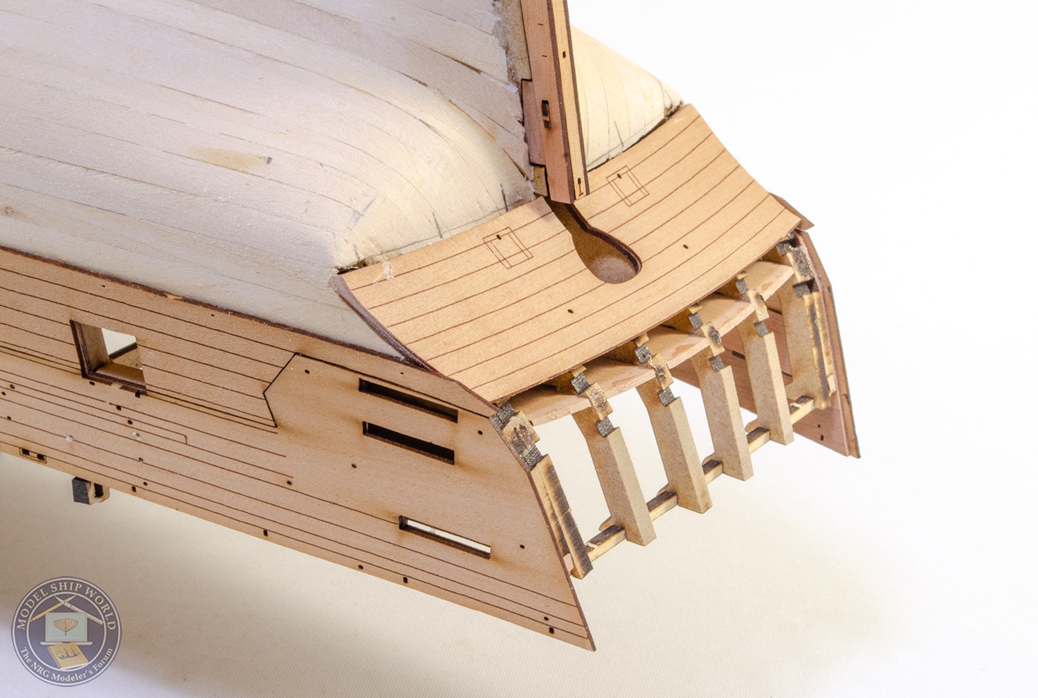
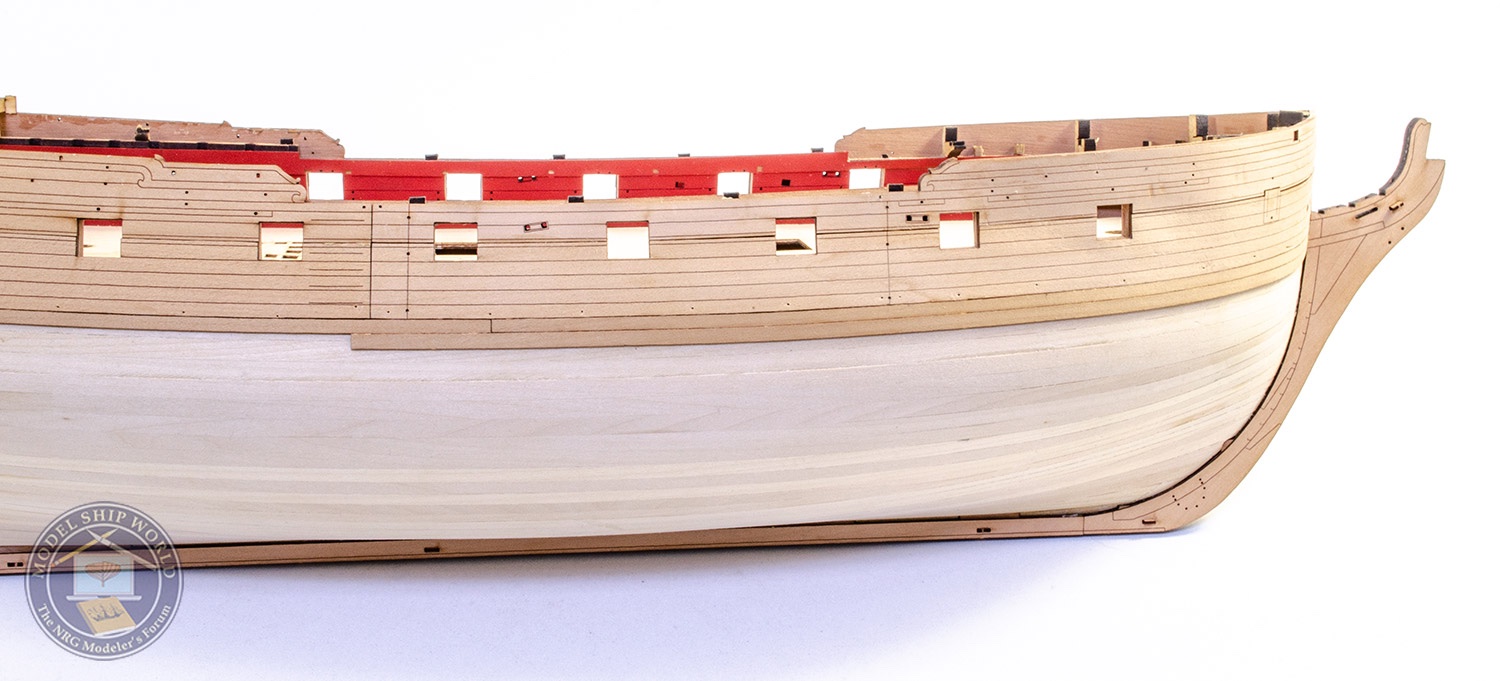
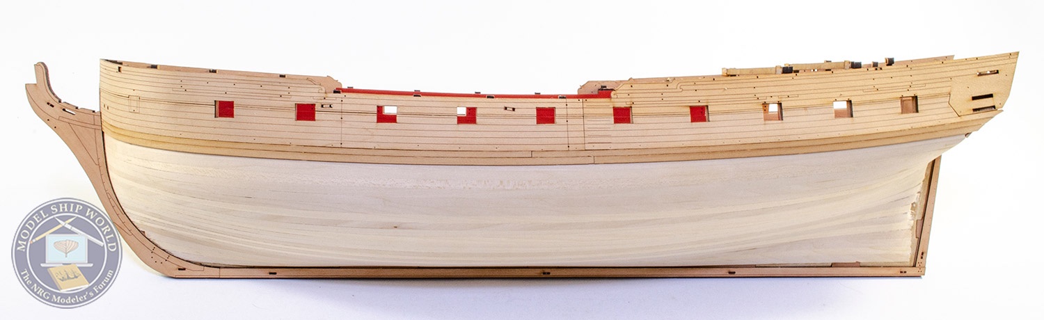
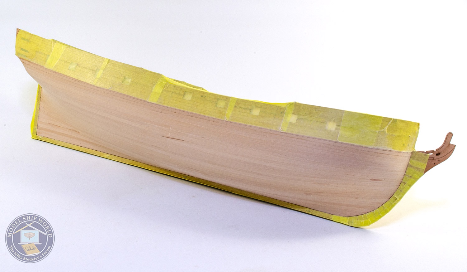
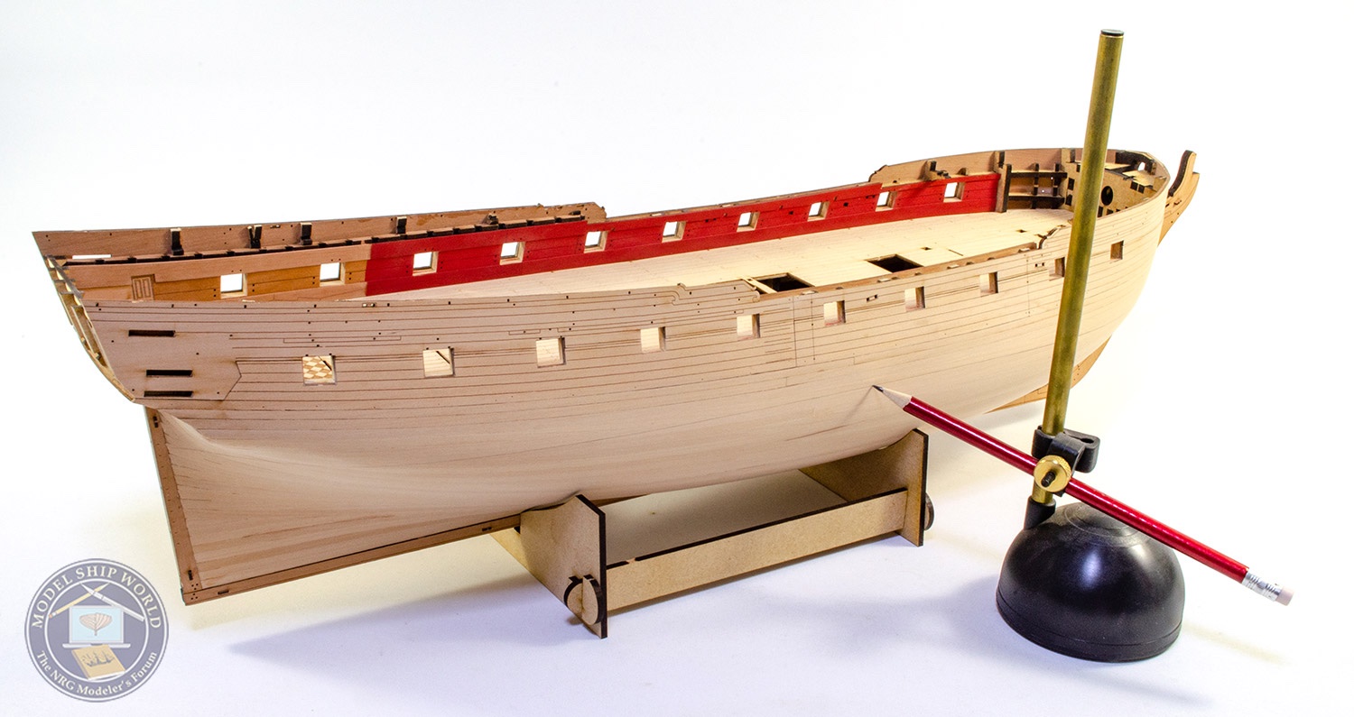
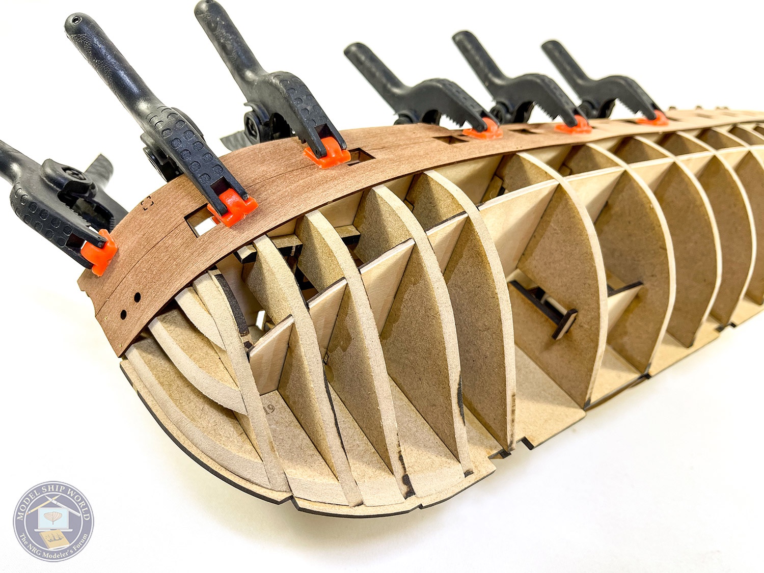
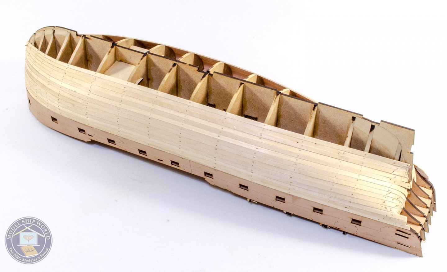
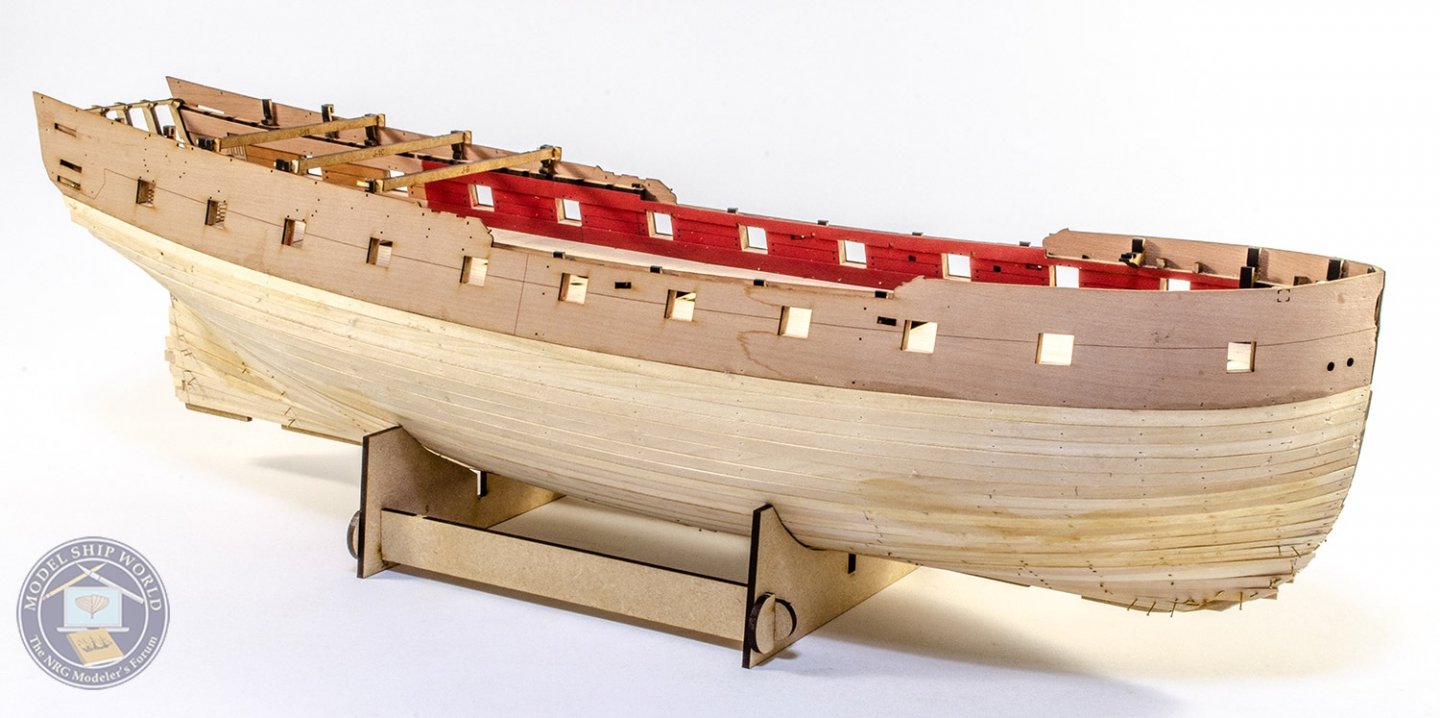
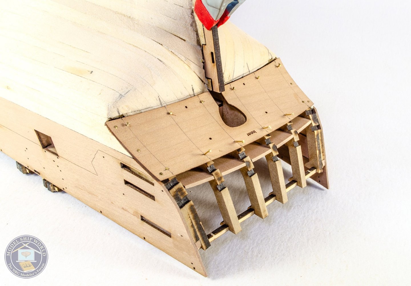
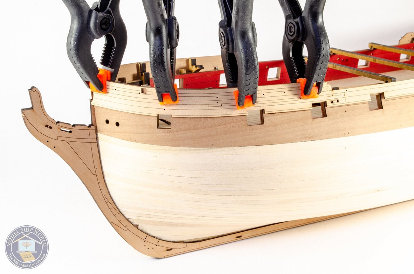
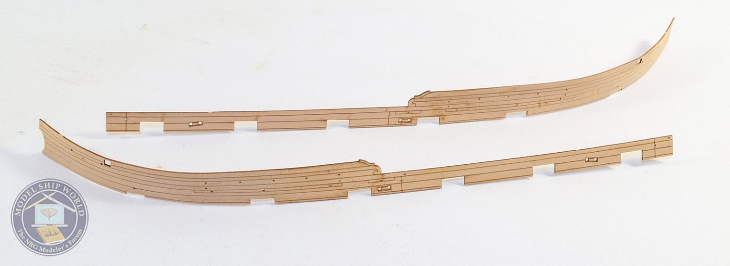
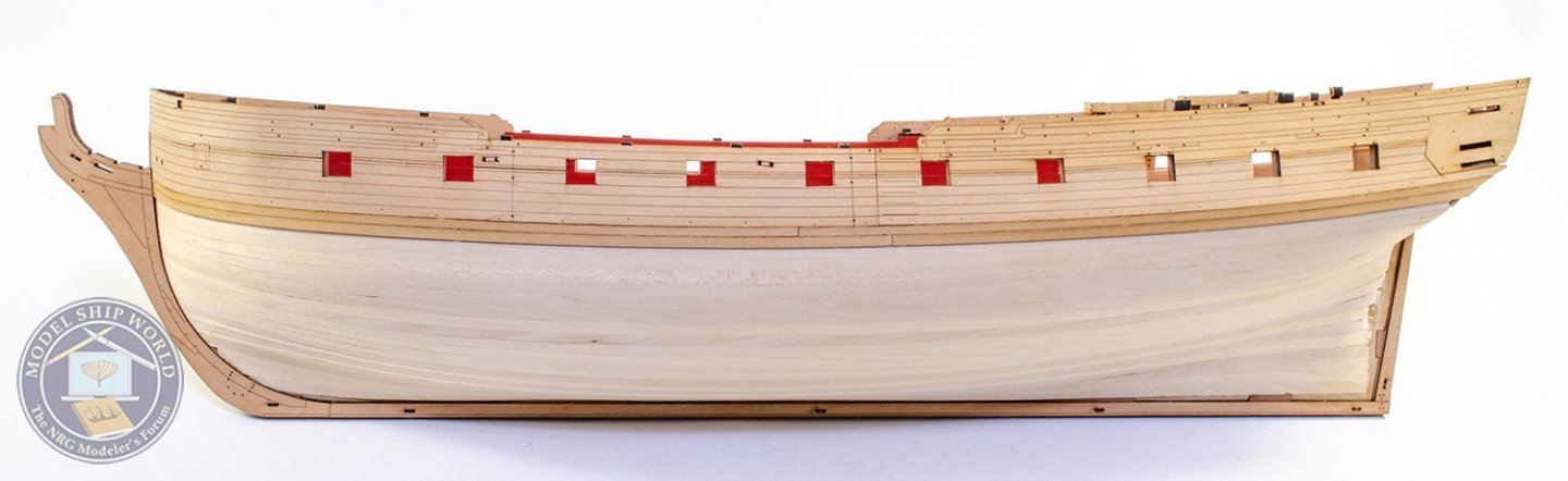
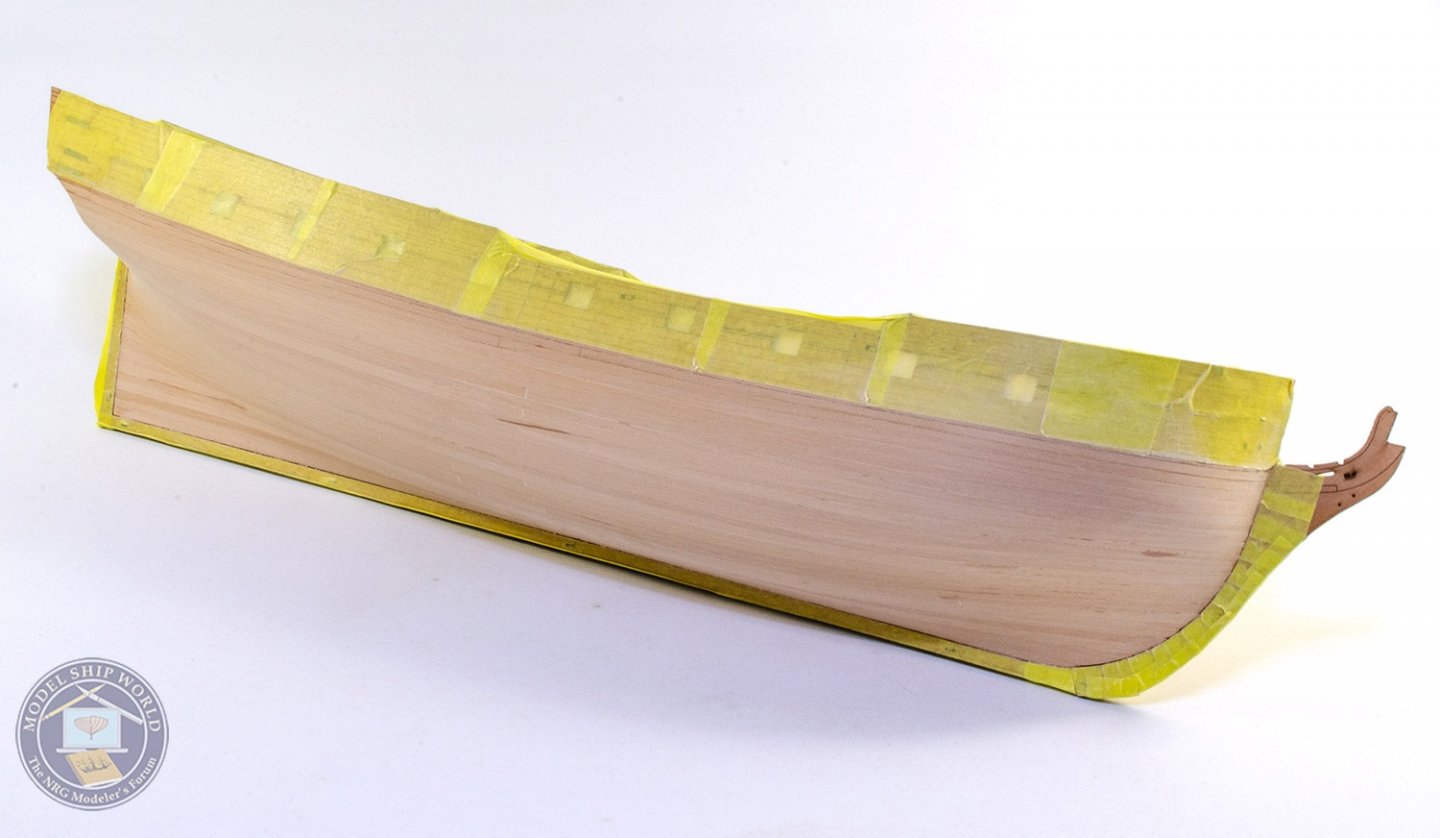
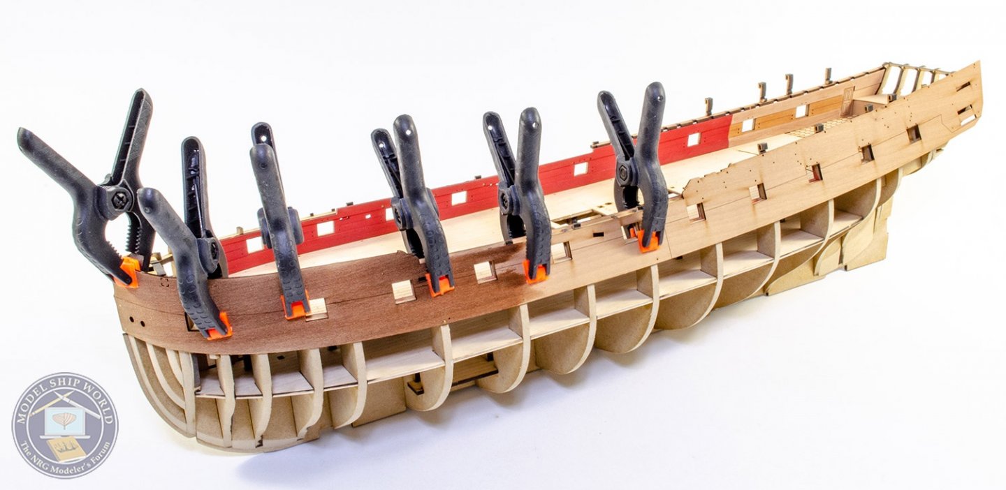
A couple of solid weeks work for this update. I've actually built quite a lot more deck stuff as well as what you see here, but I'll keep this update to the hull alone. With the first layer pear bulwarks fitted, the hull was planked in 1mm lime, tapering as I went. The shape of this hull is actually very friendly when it comes to planking, and I'd say it's ideal for anyone who's built a couple of easier models beforehand. The hull is then sanded smooth. The stern counter can be fitted direct, but I opted to soak and curve it first, marking on the positions of the MDF frames underneath so that I can pin it properly. Note this is the 'inner' 1mm part. The finishing outer part is 0.6mm and can be glued straight over this later. All inner 3mm pear keel parts (keel, prow and stern rudder post) are now glued in position. As with Chris' other designs, the keel is then covered with engraved external faces. These are located with pegs and then they are fitted, they create a natural rabbet for the second layer pear planking. The second layer doesn't start with planks, but with eight pre-cut sections that are shaped and engraved (4 per side). The fore ones are again soaked and left to dry out overnight so they come back to their original size (pear expands quite a lot when wet). The outer stern counter is now glued into place. Again, before planking, there are two pre-shaped plank layers to add, directly below the previous parts. NOW we can do the second layer planking! These are full length strips of 0.8mm x 4mm pear. These are fitted with CA gel (Gorilla Glue) spots, and tapered as I go along. As all the second layer is now on, and there's little chance of the bulwarks spreading outwards, the temporary jigs are all removed and their positions cut down. Before sanding down the second layer, the engraved areas are first masked off to prevent any possible damage. Sanding this one down was also quite easy too due to the 4mm wide planks. A temporary waterline is now added. This is so I can add any filler I need below this area without it being seen in an unpainted area. That's pretty much where I'm up to now. In fact....I'm off to add the filler right now.


- 355 replies
-
- 46
-
-
- vanguard models
- Sphinx
- (and 1 more)
-
Good morning! There will be full cannon at each position. No dummy barrels anywhere etc.
-
Looks a real nice kit, and good to see they used MDF for the keel too. Some of the ply seen in these kits end up like a banana. Hope to see you tackle this one some time.
-
Any warp in that sheet shouldn't matter when the frames are assembled. It will pull straight. I'm more concerned about where that moisture will go to (or not) with a large metal sheet over damp MDF.
-
Kit Review Harbor Tug WARATAH 1902 - HMV - 1/250 - CARD
James H replied to ccoyle's topic in REVIEWS: Model kits
Paper modelling is still alchemy to me. I have amazing respect for those who can build this stuff like I've seen. -
Outstanding! 👍
-
Pins are pushed through the pear and into the MDF below.
- 355 replies
-
- 7
-

-
-
- vanguard models
- Sphinx
- (and 1 more)
-
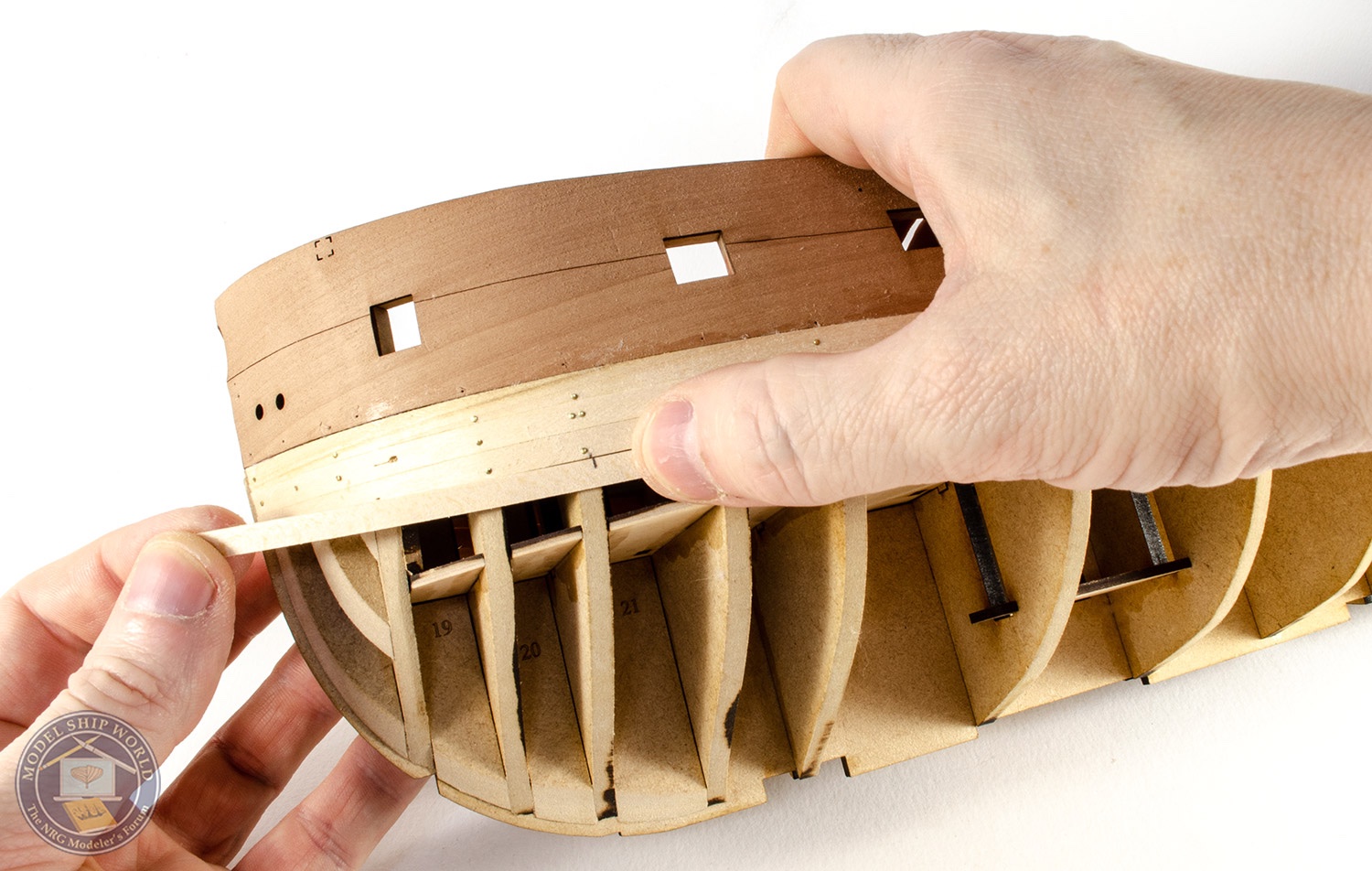
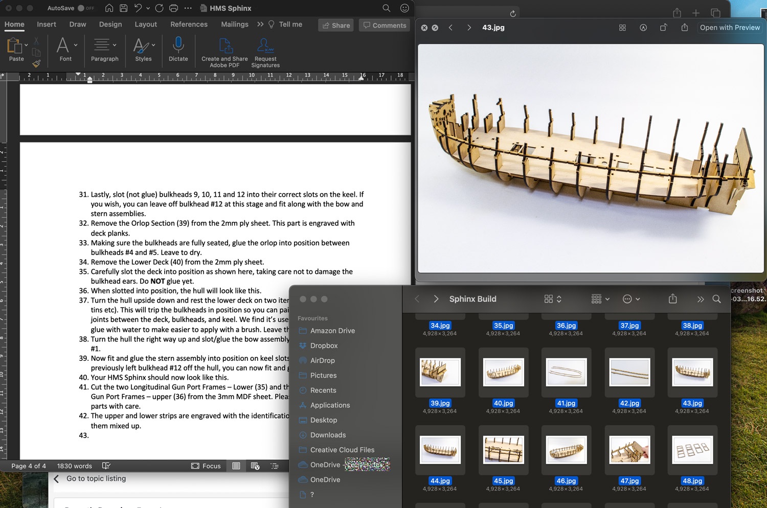
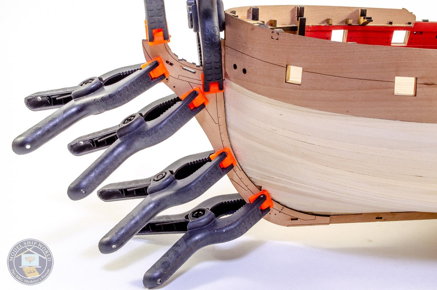
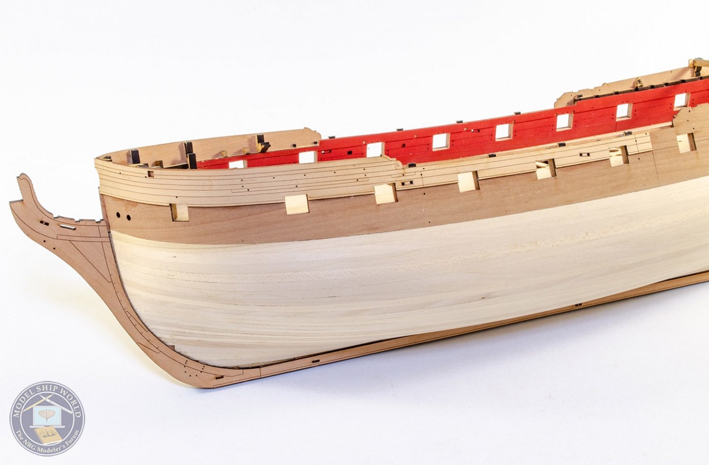
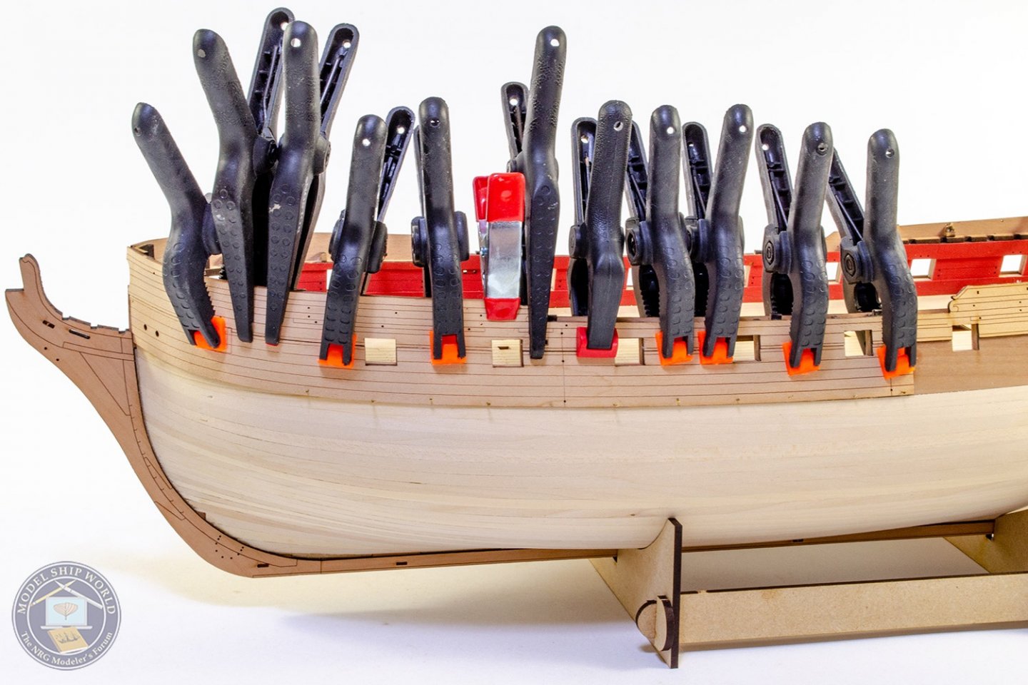
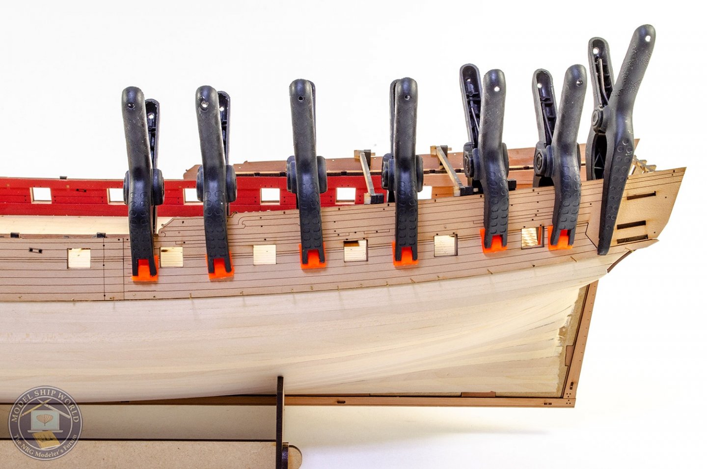
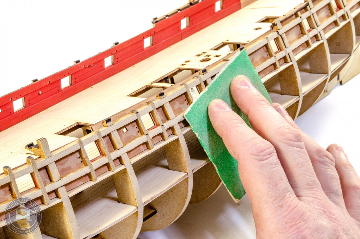
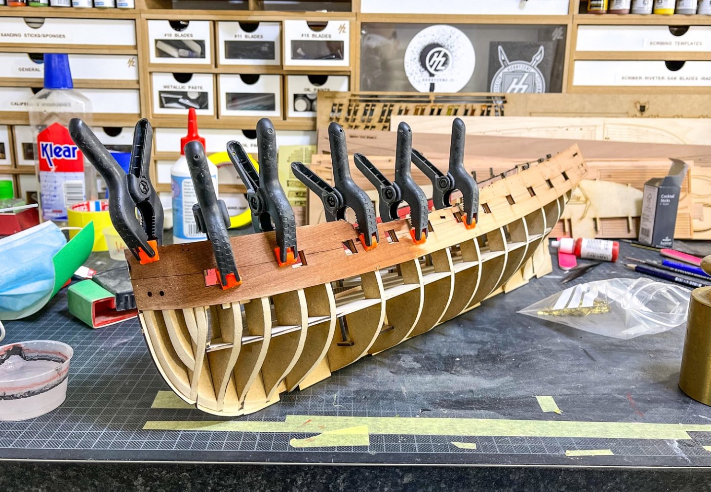
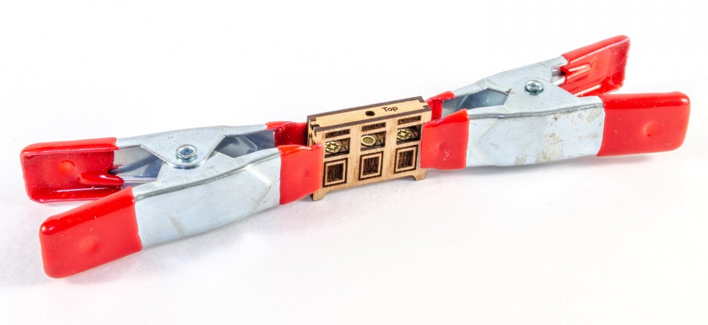
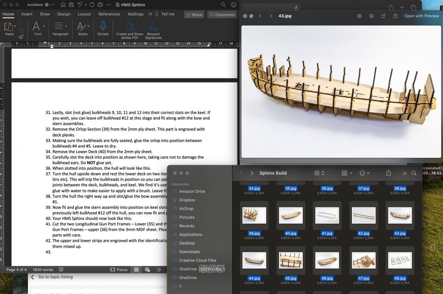
Today, I finished fairing the hull. At least it's one time I wear a mask where I don't actually mind doing it! Again, a good indicator or when this is done is when the char is gone. Fairing the bow and stern assemblies first saves a whole lot of time too. Next up are the external pearwood bulwarks (first layer). Before these can be fitted, they need to be pre-bent. Each one is soaked in hot water for about 45 mins, by time the water has then gone cold! The bulwarks are then taken straight from the water and laid onto the MDF frame, and clamped. It's also pinned through the pear and into the MDF in some places that are awkward to clamp. When dry, these will be taken off and then properly aligned and glued. You can see from these pics just how the bulwark clings pretty much to the whole area of faired bulkheads, so there's no ripple/gaps you need to negotiate. And just to prove I'm also an untidy worker and these photos are a facade, here's the desktop. Until next time...

- 355 replies
-
- 34
-
-
- vanguard models
- Sphinx
- (and 1 more)
-
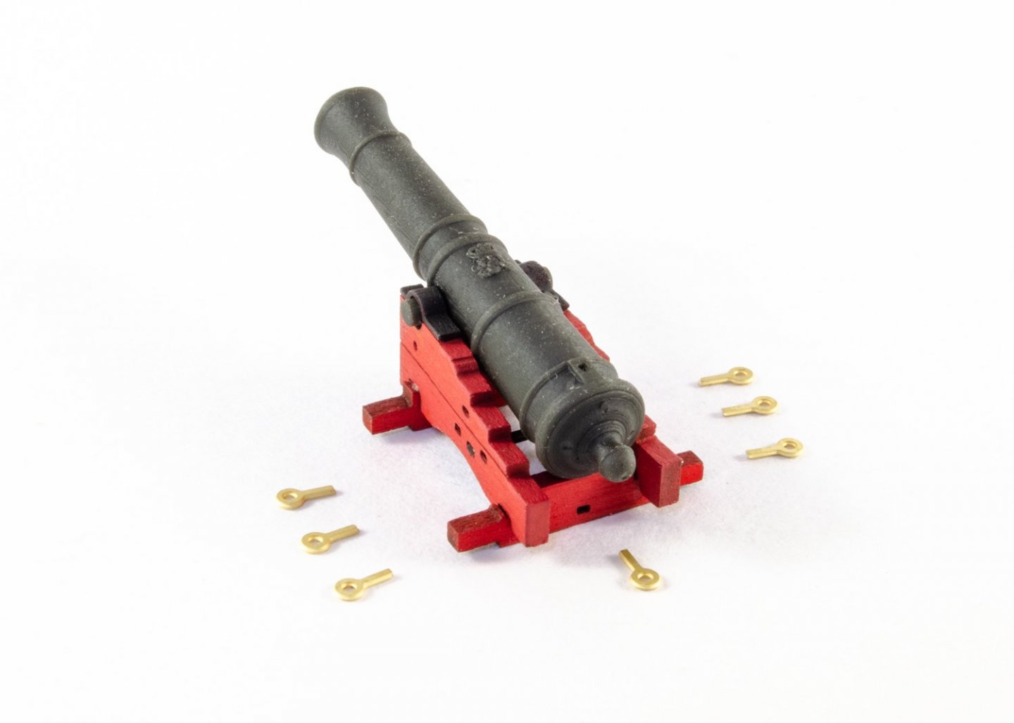
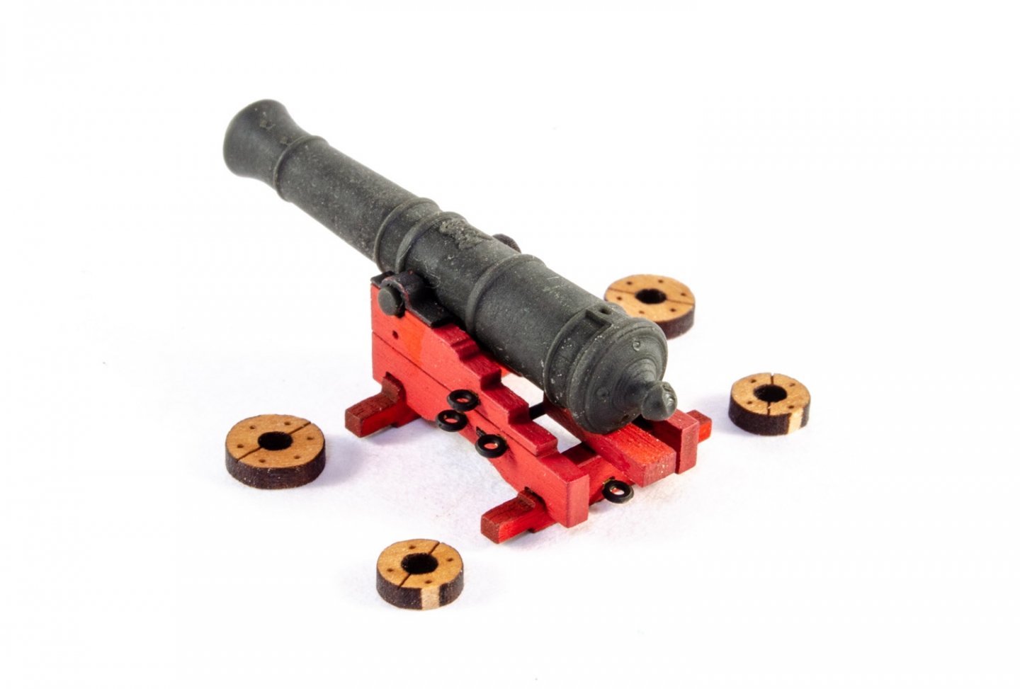
You can always replace them eyelets of your choice, of course.
- 355 replies
-
- 6
-
-
- vanguard models
- Sphinx
- (and 1 more)
-
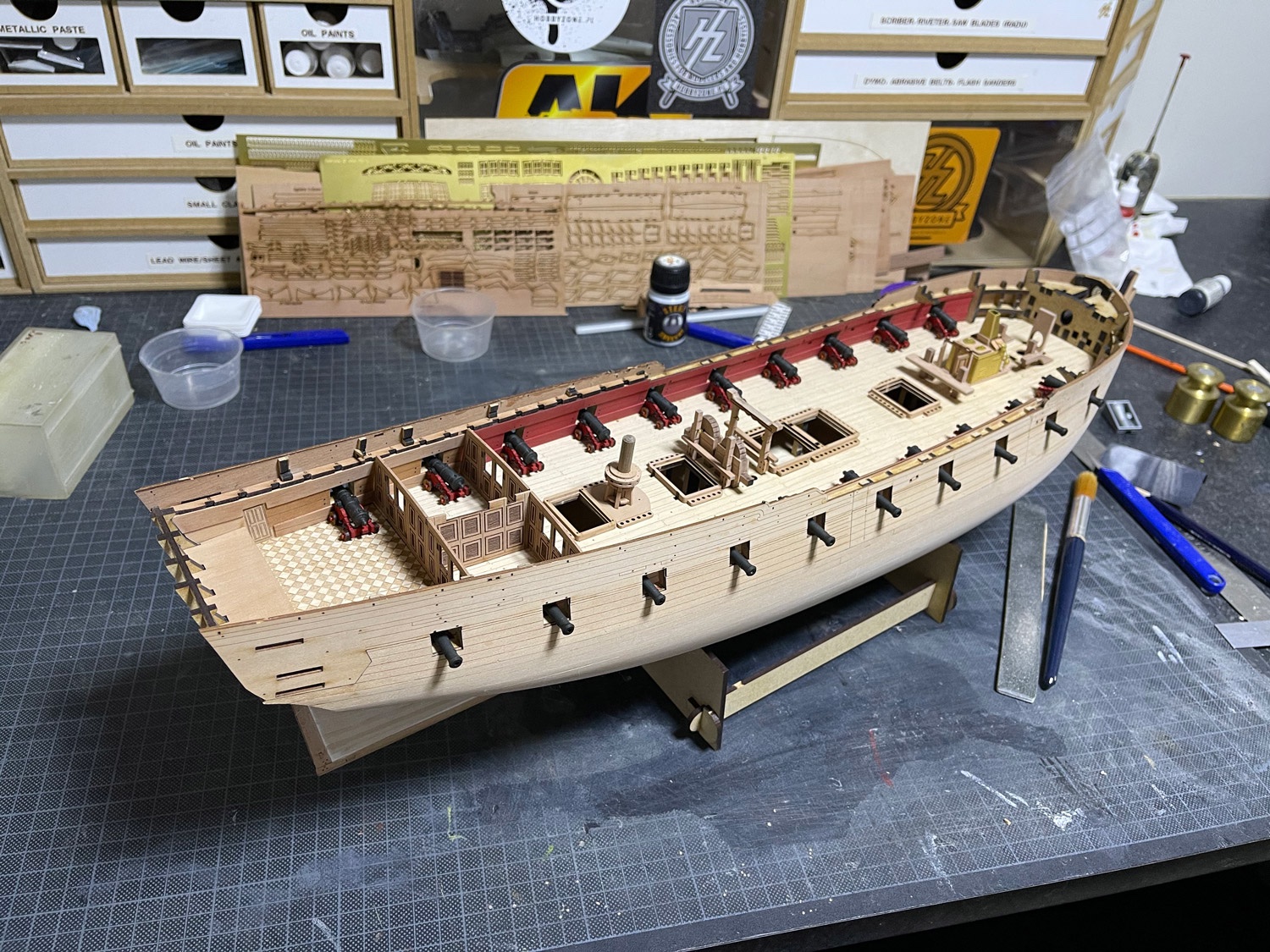
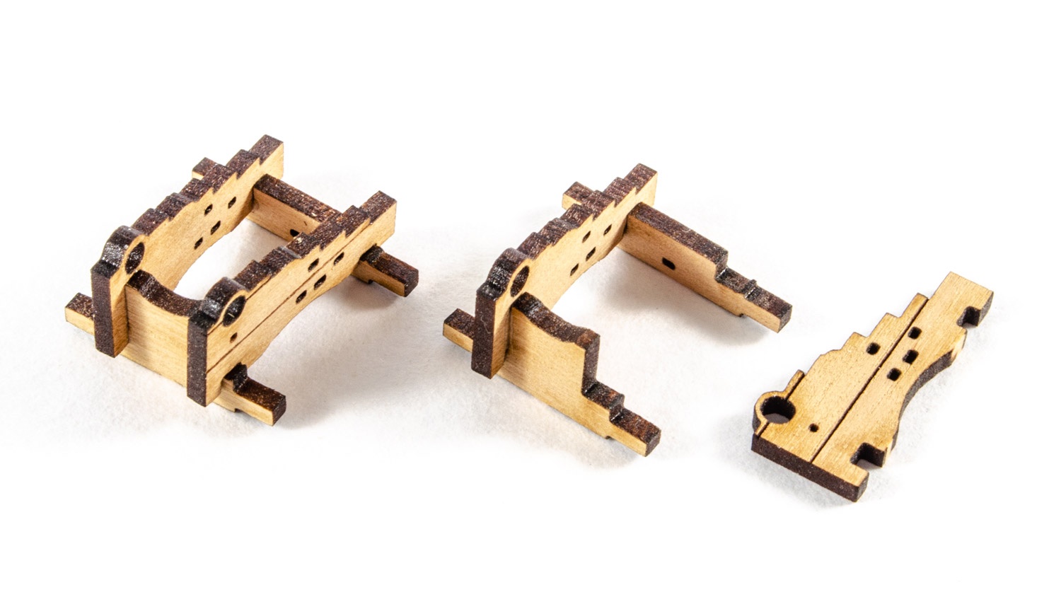
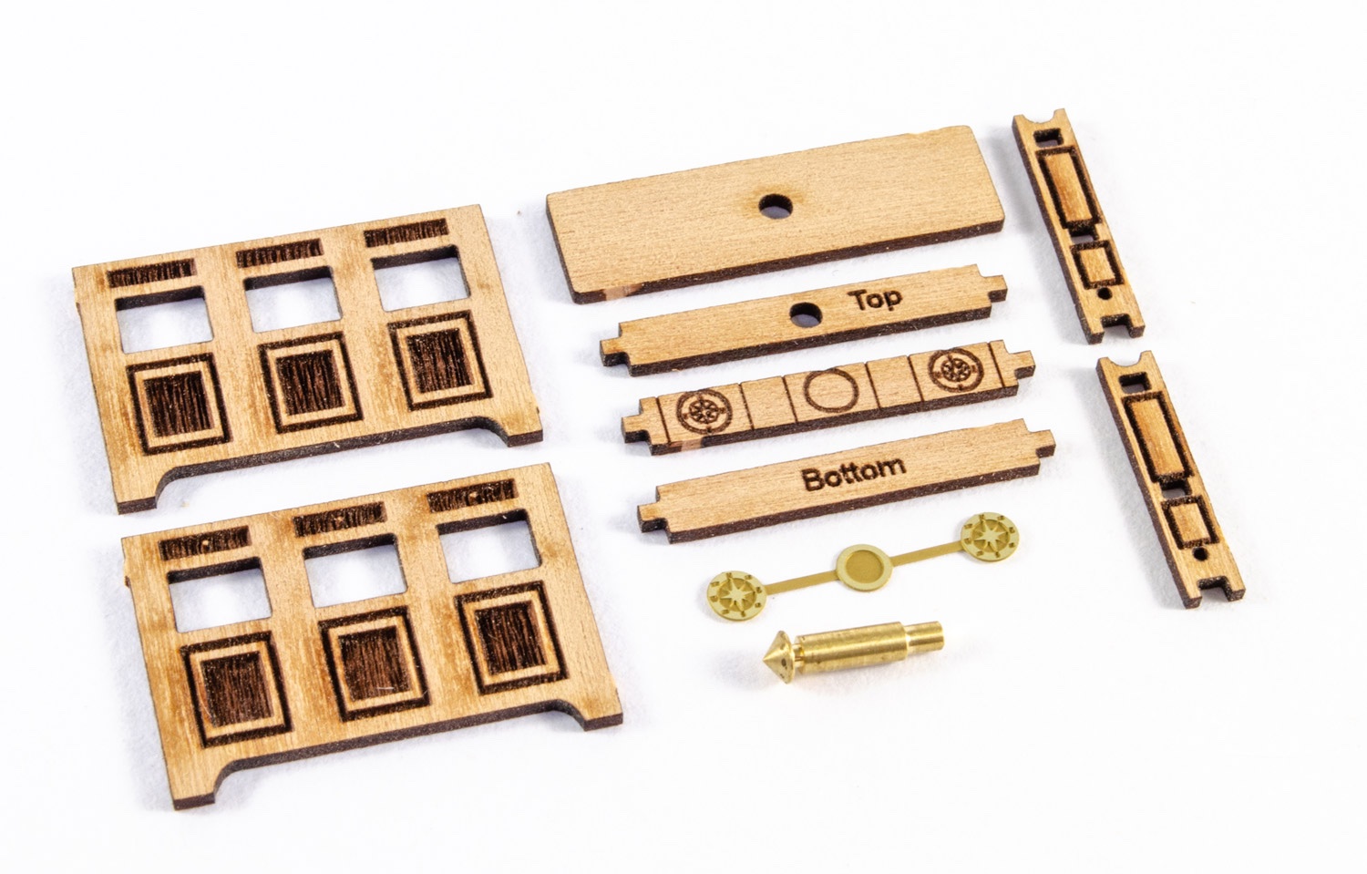
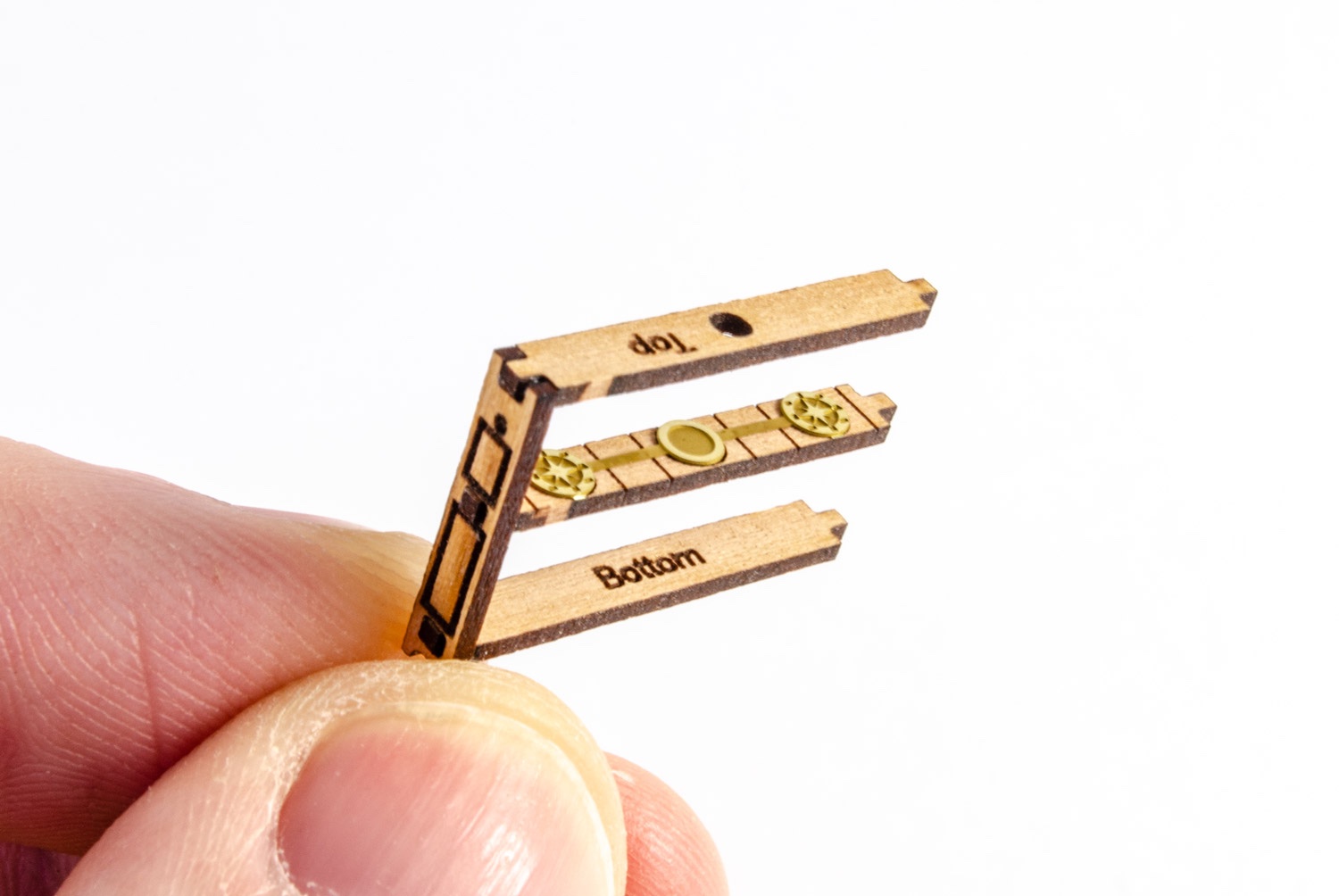
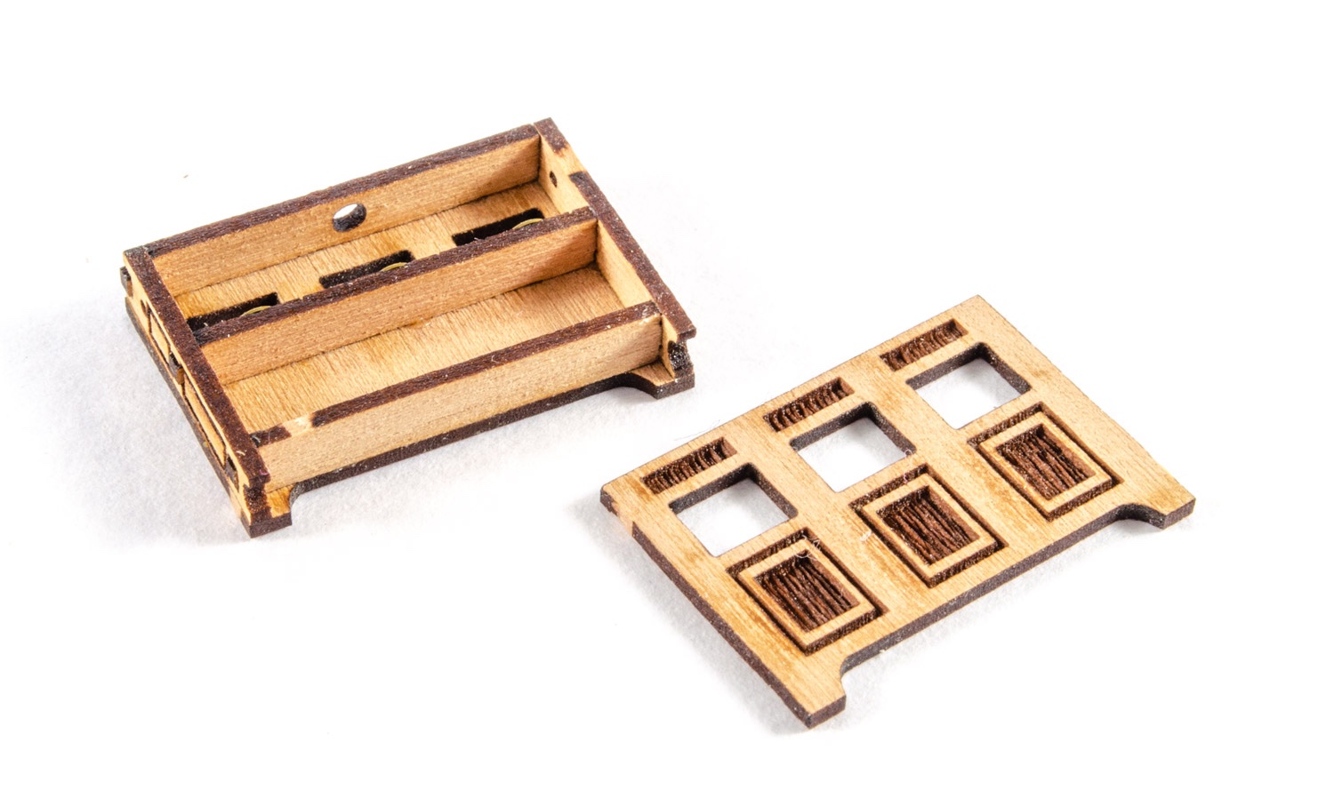
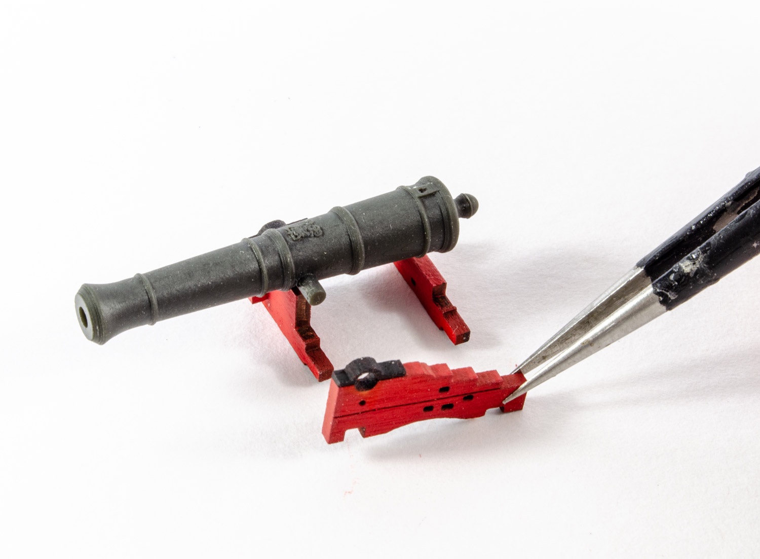
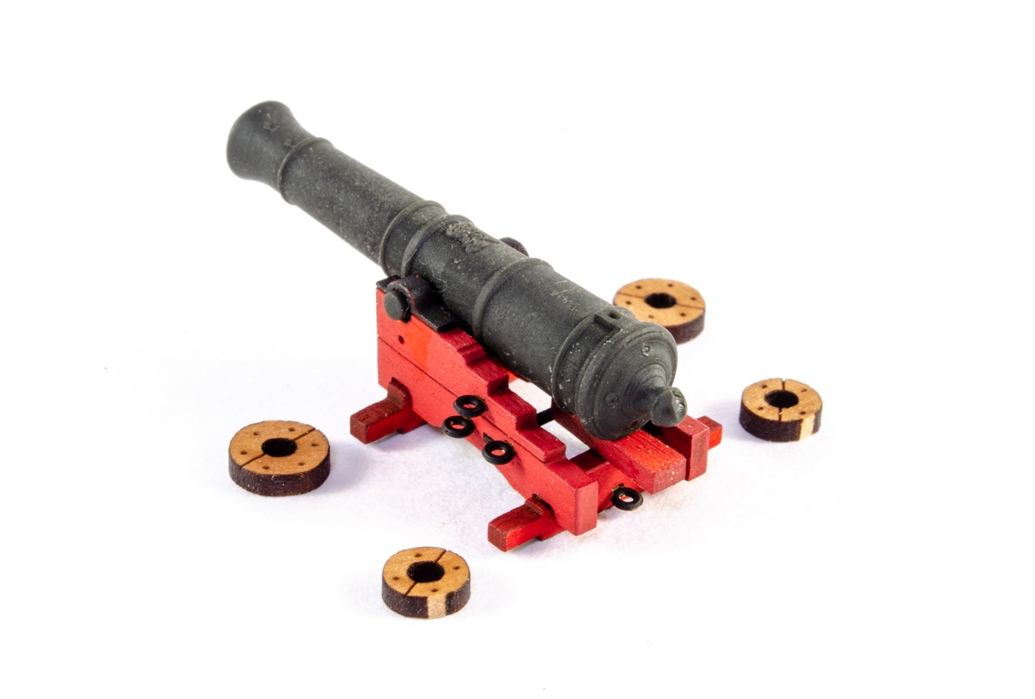
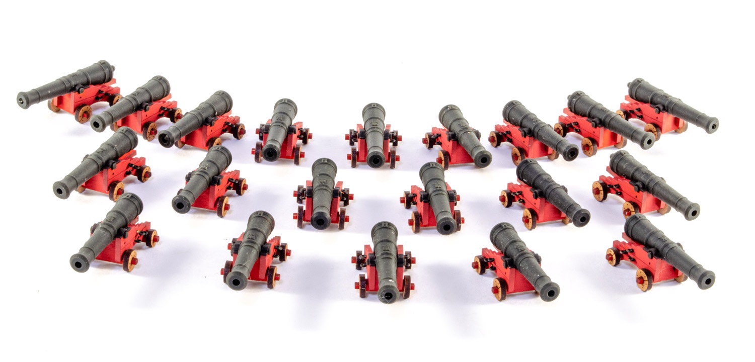
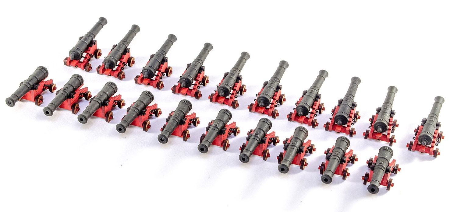
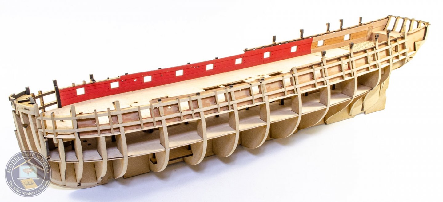
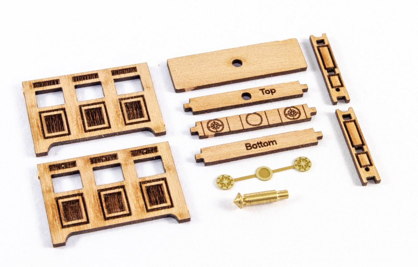
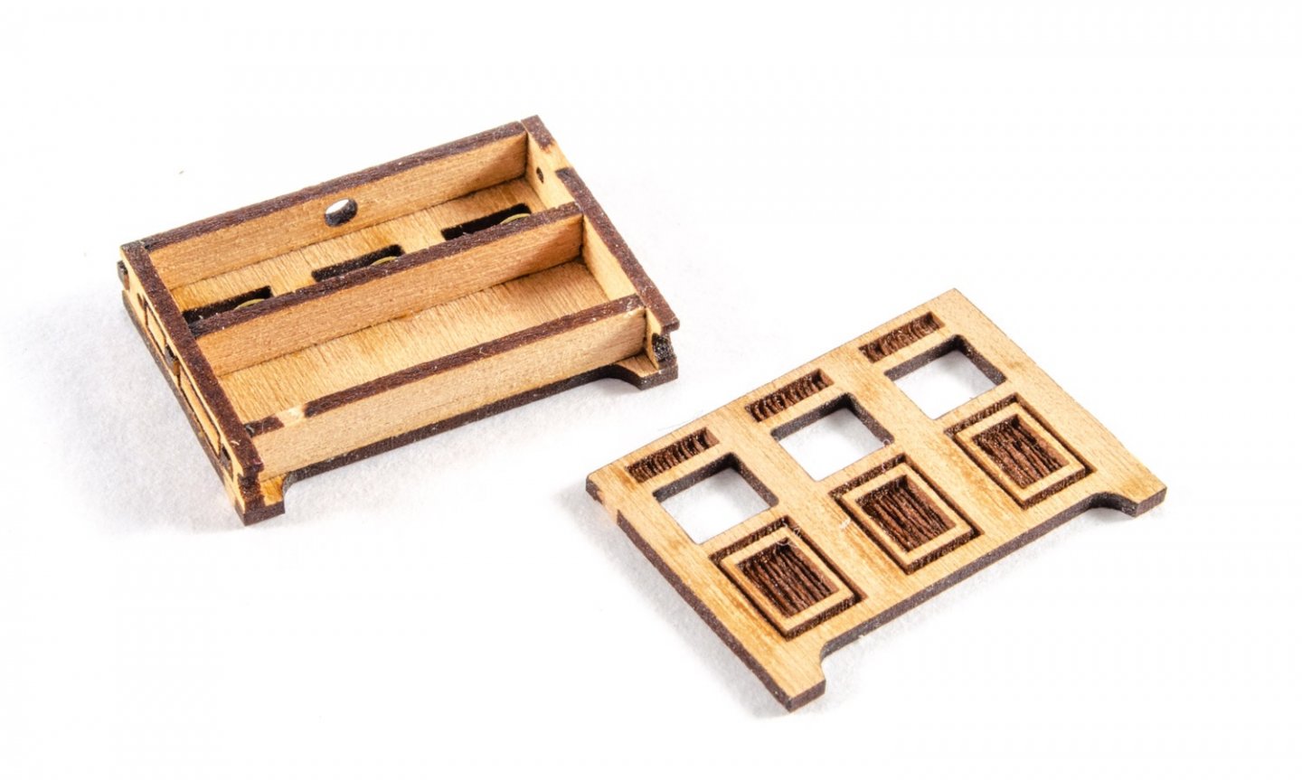
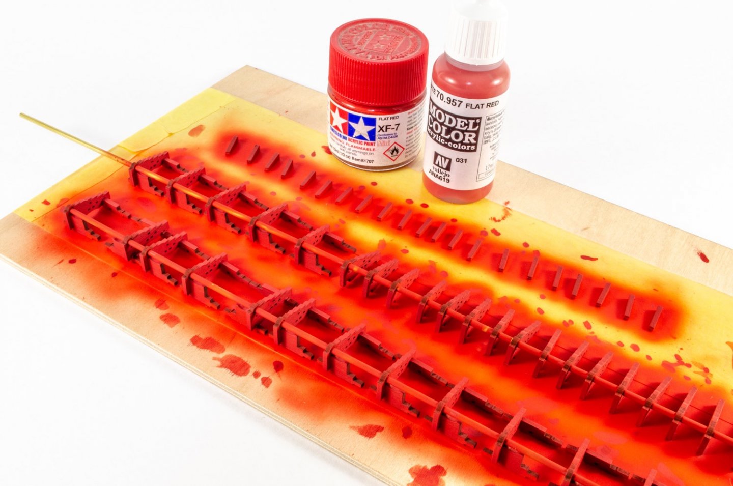
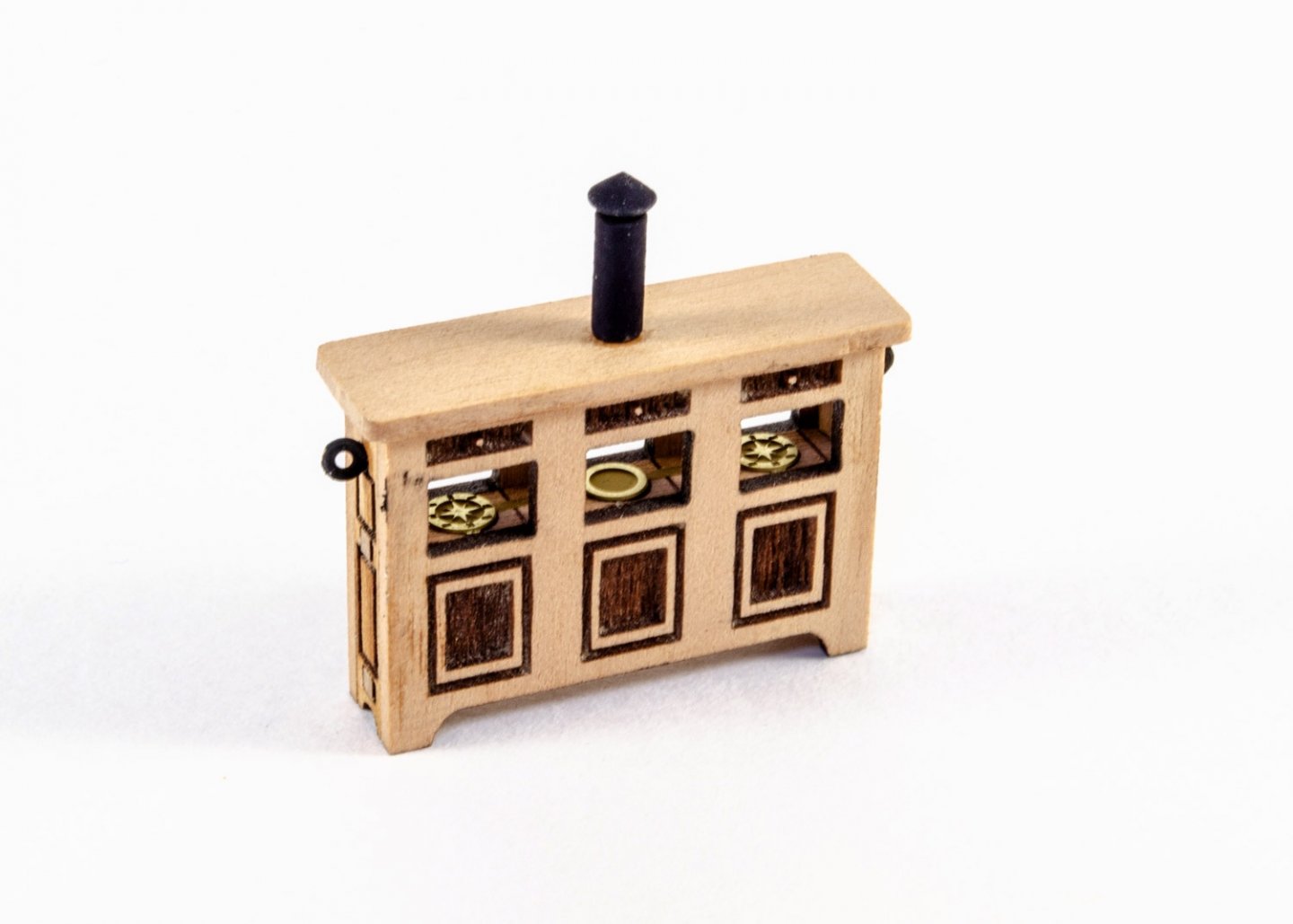
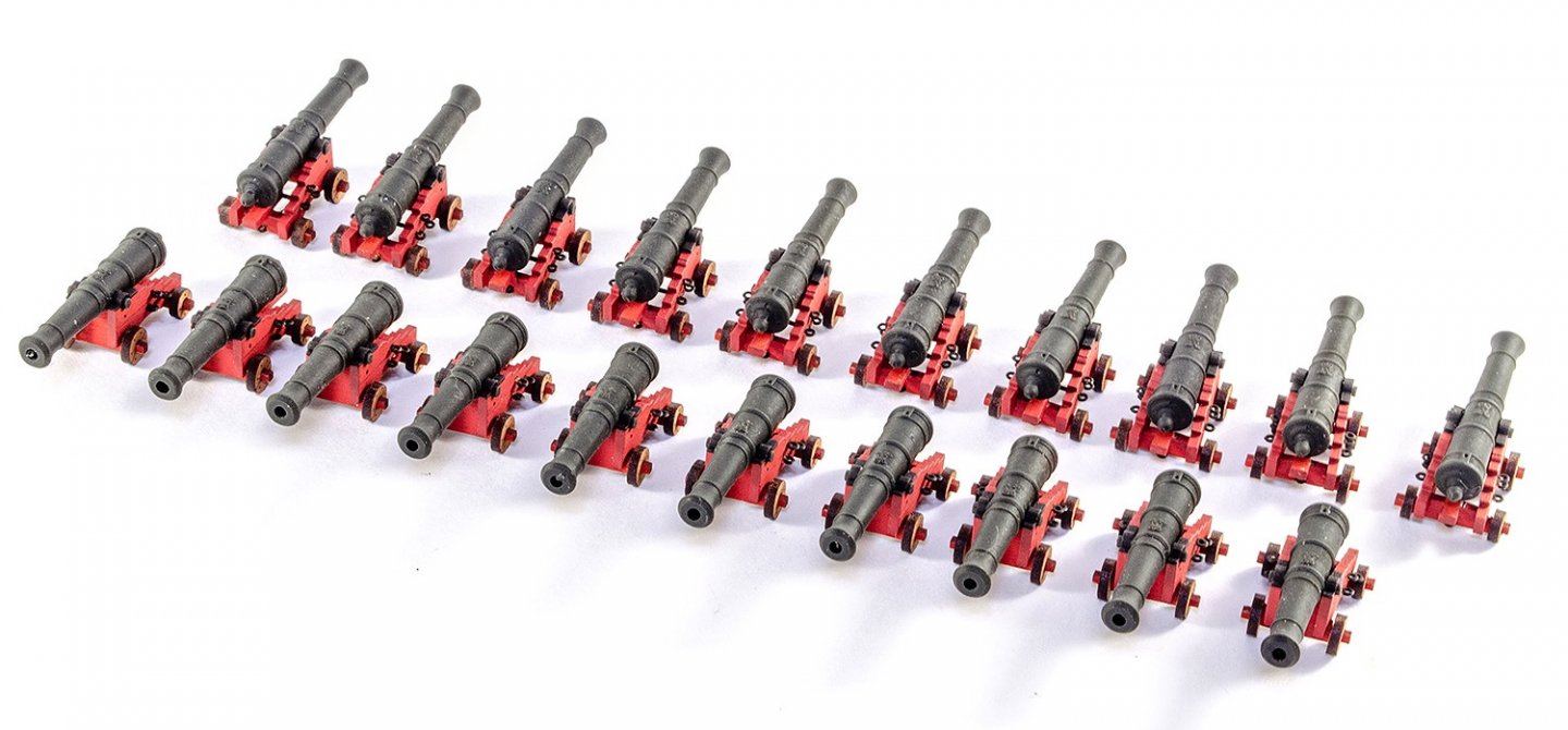
Just a small update. Sphinx comes with a series of jigs to ensure that the bulwarks are always properly spaced throughout your build as the upper decks will depend on it. There is always a little leeway, but at least you can check things as they are planked etc. These are the jigs which are not glued into position. I'm halfway through fairing the hull, but been doing some other stuff between tasks. This time I turned my attention to the 20 cannon and the binnacle. The binnacle is a nice, easy item to construct and there's little to do wrong. In fact, I can't see how anyone could stuff this up. The cannon are also very easy, just time consuming as mass producing any one individual item always is. Note that with these, there are no fiddly PE capsquares to fit. This time, they are a part of the pearwood carriage sides. So no awkward bending and fitting to do. What this does mean is that you will need to paint the carts before complete assembly. It's easy enough, and a little paint is just scraped away before gluing the side into position on the rest of the assembly. The guns are also black resin, so no painting needed. Back to fairing the hull in the morning, then I can get onto fitting the first layer outside bulwark and the first layer of planking. Until then...


- 355 replies
-
- 37
-
-
-
- vanguard models
- Sphinx
- (and 1 more)
-
A lovely kit. You should do this one pretty quickly.
- 160 replies
-
- 1
-
-
- Alert
- vanguard models
- (and 1 more)
-
Putting the manual together is what Chris does. I create the text and photos (editing in Lightroom and Photoshop). I might also annotate these with Illustrator too, to make things even clearer. I think @chris watton uses InDesign, but I'm sure he'll correct me if I'm wrong.
- 355 replies
-
- 5
-
-
- vanguard models
- Sphinx
- (and 1 more)
-
Before I head to the cave and work on some deck stuff, I'm spending some time on photos and captions for the manual. This will save me the gargantuan task later on 😬
- 355 replies
-
- 18
-
-
- vanguard models
- Sphinx
- (and 1 more)
-
I think so. My personal aim is 12 weeks or thereabouts. Then the manual needs to be done, including plans printed, box art labels done etc.
- 355 replies
-
- 6
-
-
- vanguard models
- Sphinx
- (and 1 more)
-
Just outstanding The whole model, and that interior finish. Beautiful.
-
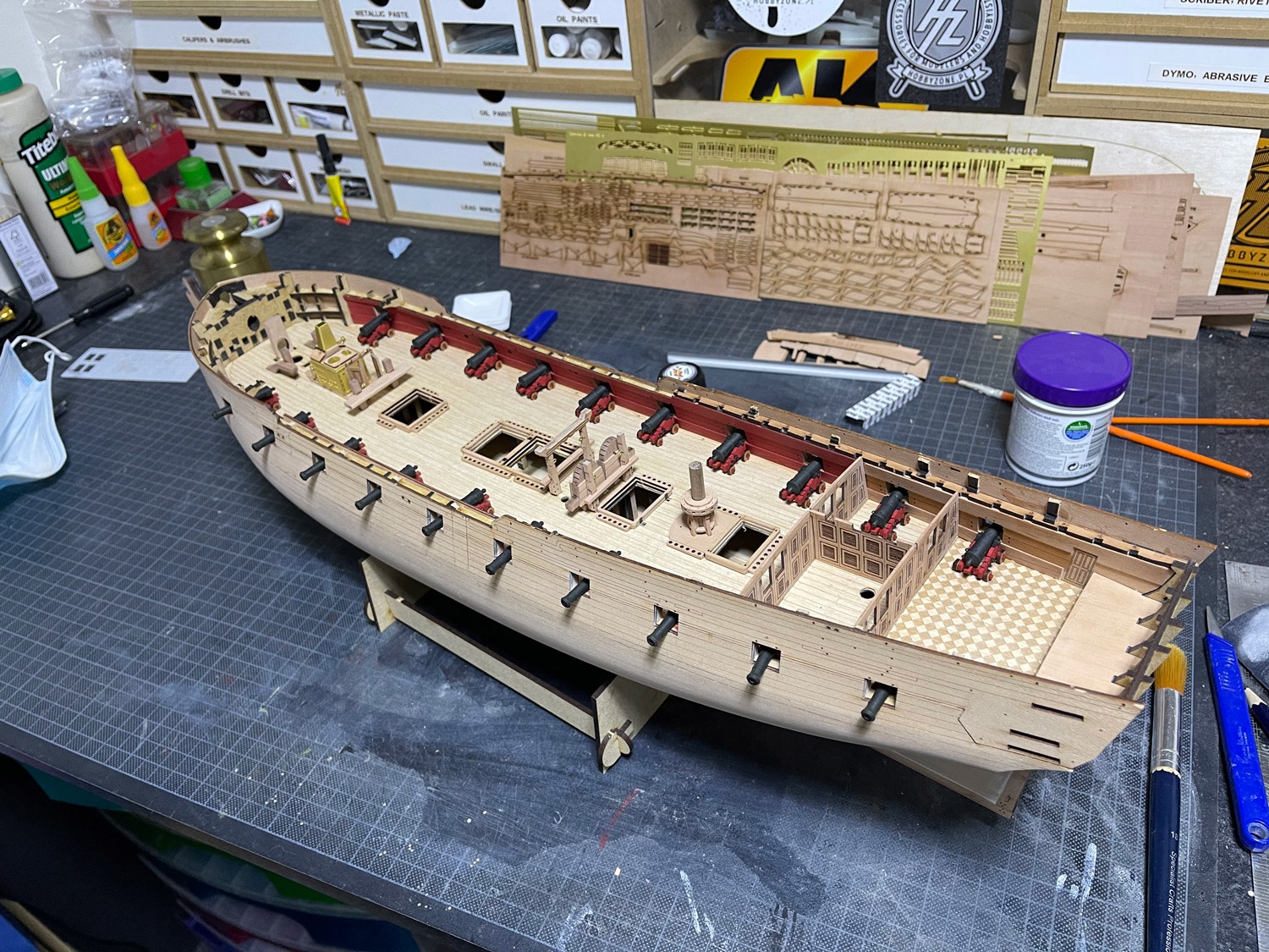
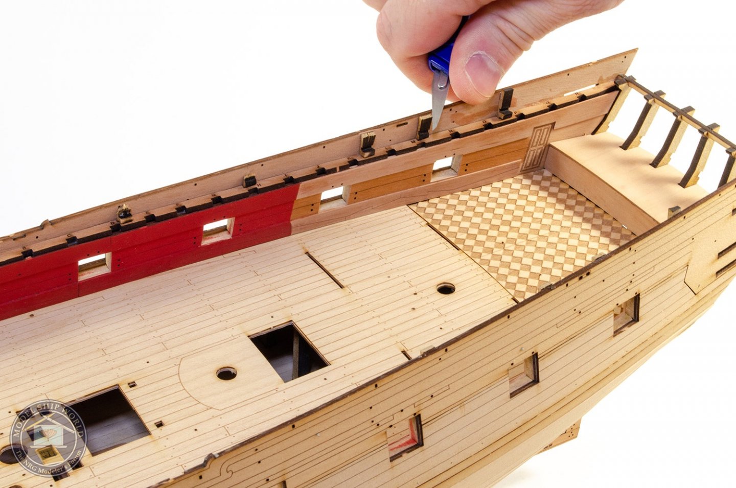
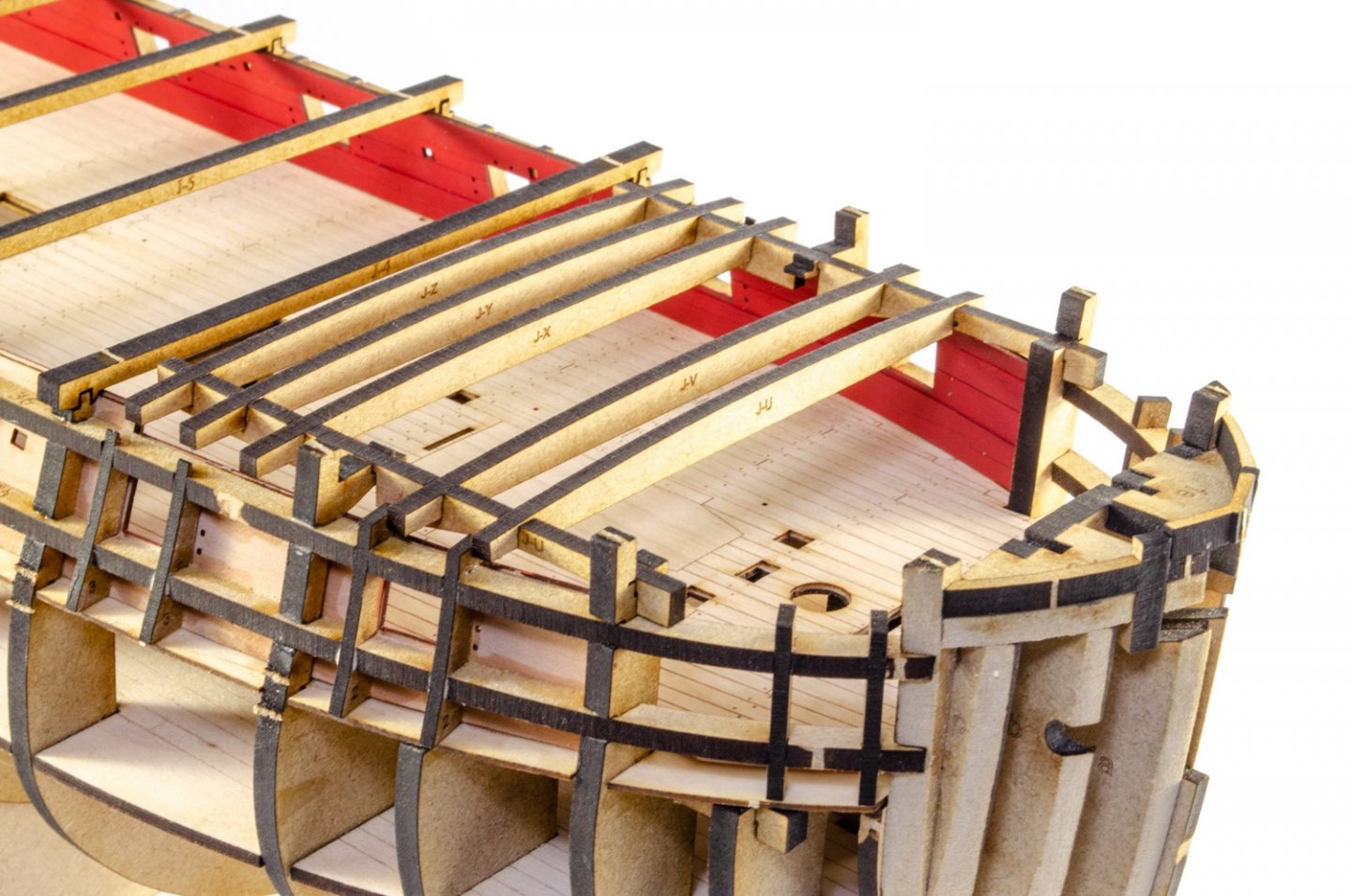
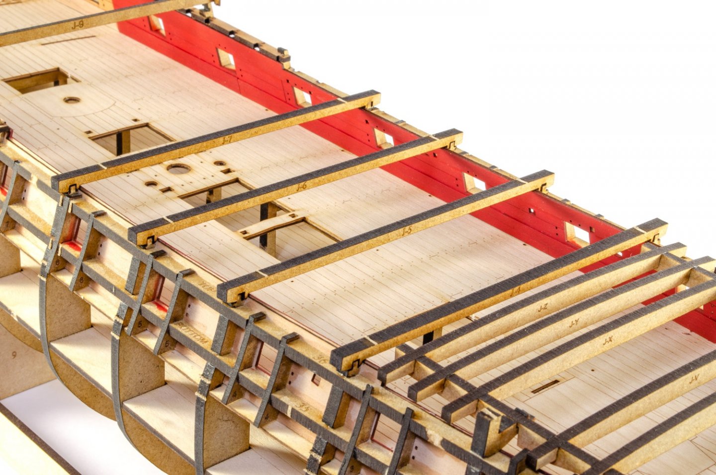
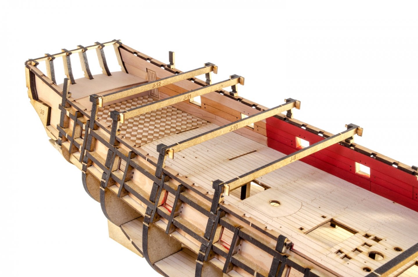
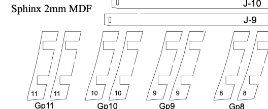
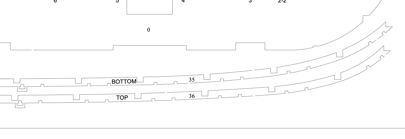
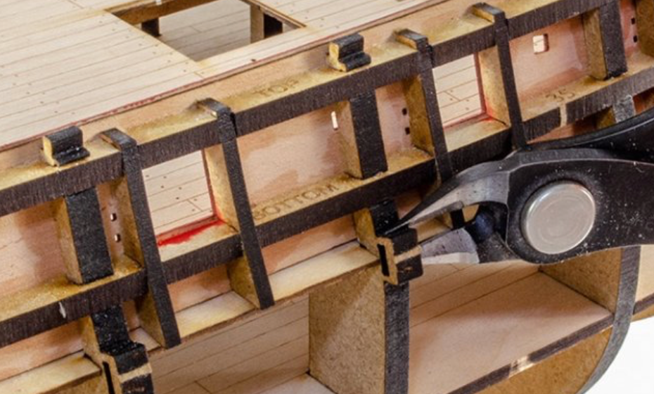
The long strips I first fitted to the bulkheads, are the top and bottom sides of the gun ports. These can only fit in one way. The gun ports are numbered 1 - 11 from bow to stern, and the side frames are fitted in pairs, slotting into the positions on the strips I just mentioned.
- 355 replies
-
- 17
-
-
-
- vanguard models
- Sphinx
- (and 1 more)
-
Mantua "blue painted" photo-etched brass
James H replied to Alexisgm97's topic in Metal Work, Soldering and Metal Fittings
Pretty sure the blue areas are the remaining photo-resist film from production (from my old days in circuit board manufacture). That should be easy to gently sand away, or even peel, depending on thee type of resist (ink or film). When I built this model, I painted blue (I think) in the bare brass areas, then rubbed the parts over some very fine grade abrasive paper to reveal the brass, and then rubbed over finer papers until it was polished. I then sealed the brass with lacquer so it didn't tarnish.