James H
-
Posts
6,135 -
Joined
-
Last visited
Content Type
Profiles
Forums
Gallery
Events
Everything posted by James H
-
 I think you purposely decided to go for eye surgery so you could watch the rest of us try and build this first. That's extreme! 😆
 -
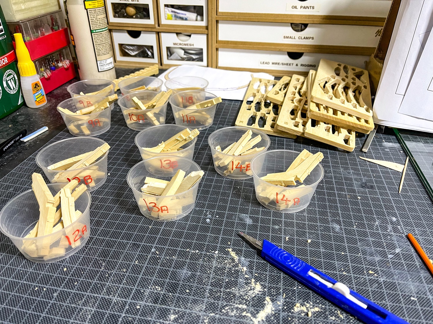
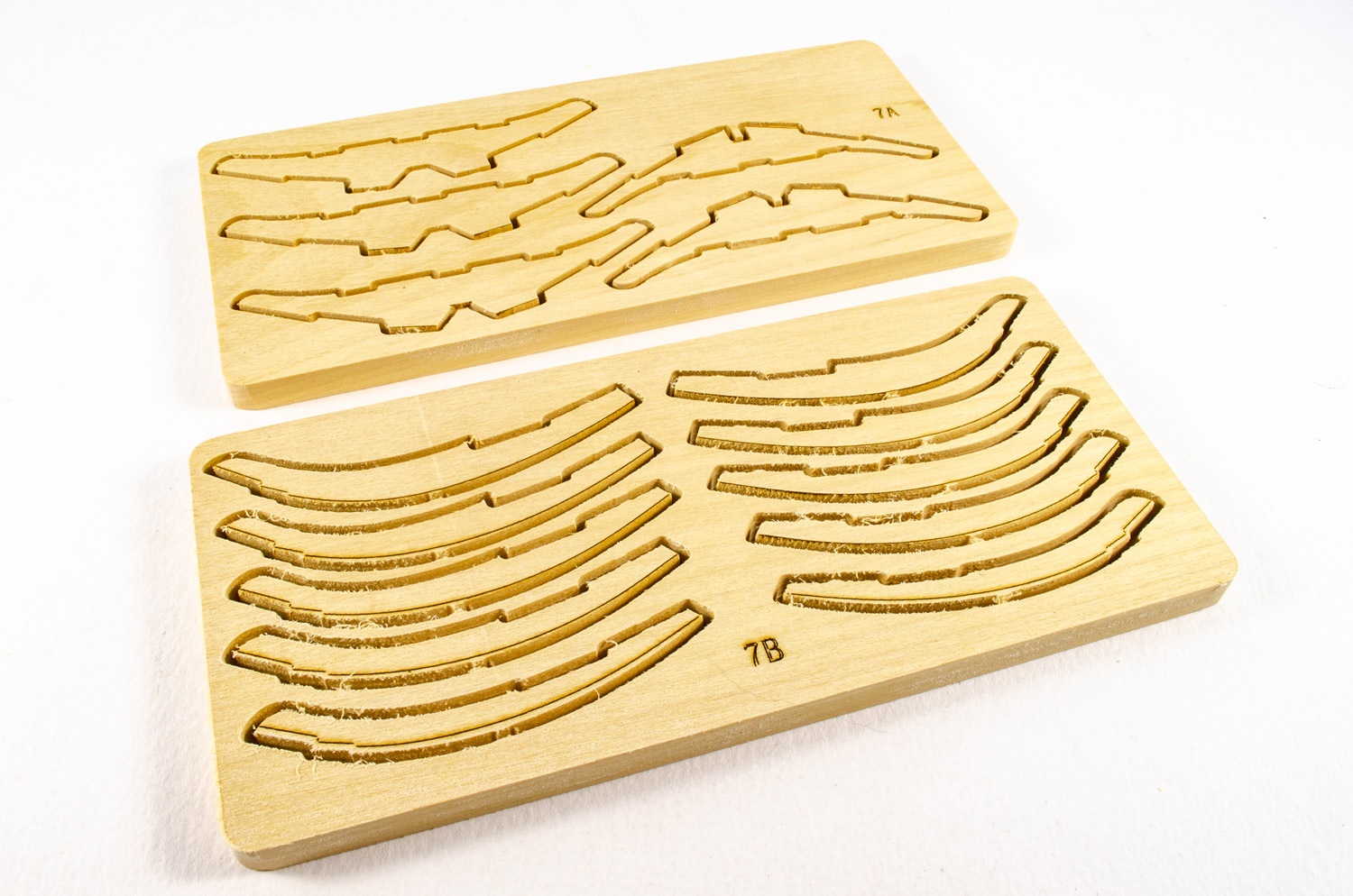
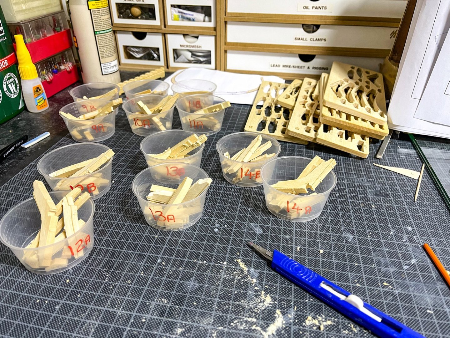
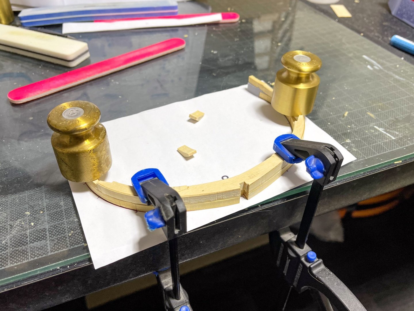
Got a little more done over the last 24hrs. Frames 7A/B, 8A/B and 9A/B are now almost built, minus bevelling. I need to fit chocks to 8A at the moment and do some refinement on all frames. Seems like a silly question, but would I actually glue the A/B frames together? It wouldn't make much sense (to me) to add another layer of potential screw-up when all frames are going to be fastened side by side in the keel....or should I glue? Maybe gluing will just create a stronger overall assembly. I'm aware that potential timber thickness tolerances could possibly cause issues if I do glue them together before fitting to keel. Whilst waiting for glue to dry under clamps etc, I took the opportunity to remove and clean up the parts for the next three double frames 9A/B, 10A/B, and 11A/B. I also removed the parts for the last three double frames 12A/B, 13A/B, and 14A/B, but these aren't yet cleaned up and the joints prepped for assembly (squaring up internal CNC curves).

- 16 replies
-
- 18
-

-
She's looking very clean. Nice work on rigging those guns too.
- 382 replies
-
- 1
-
-
- Vanguard Models
- Duchess of Kingston
- (and 1 more)
-
Absolute kudos. That work is so very neat. This is my benchmark for when I start this.
-
I just fitted those to the timbers using some rubber cement used for photo-mounting, so I hope that plan works 🤣 Also been rooting around in my attic and I think I found some suitable Madagascan ebony I can use for the wales and gunwales. If I can, that will be very neat against the boxwood-style timber.
-
kit review 1:48 HMS Granado ‘Cross Section’
James H replied to James H's topic in REVIEWS: Model kits
I've been rooting around in my attic and I think I found some suitable Madagascan ebony I can use for the wales and gunwales. -
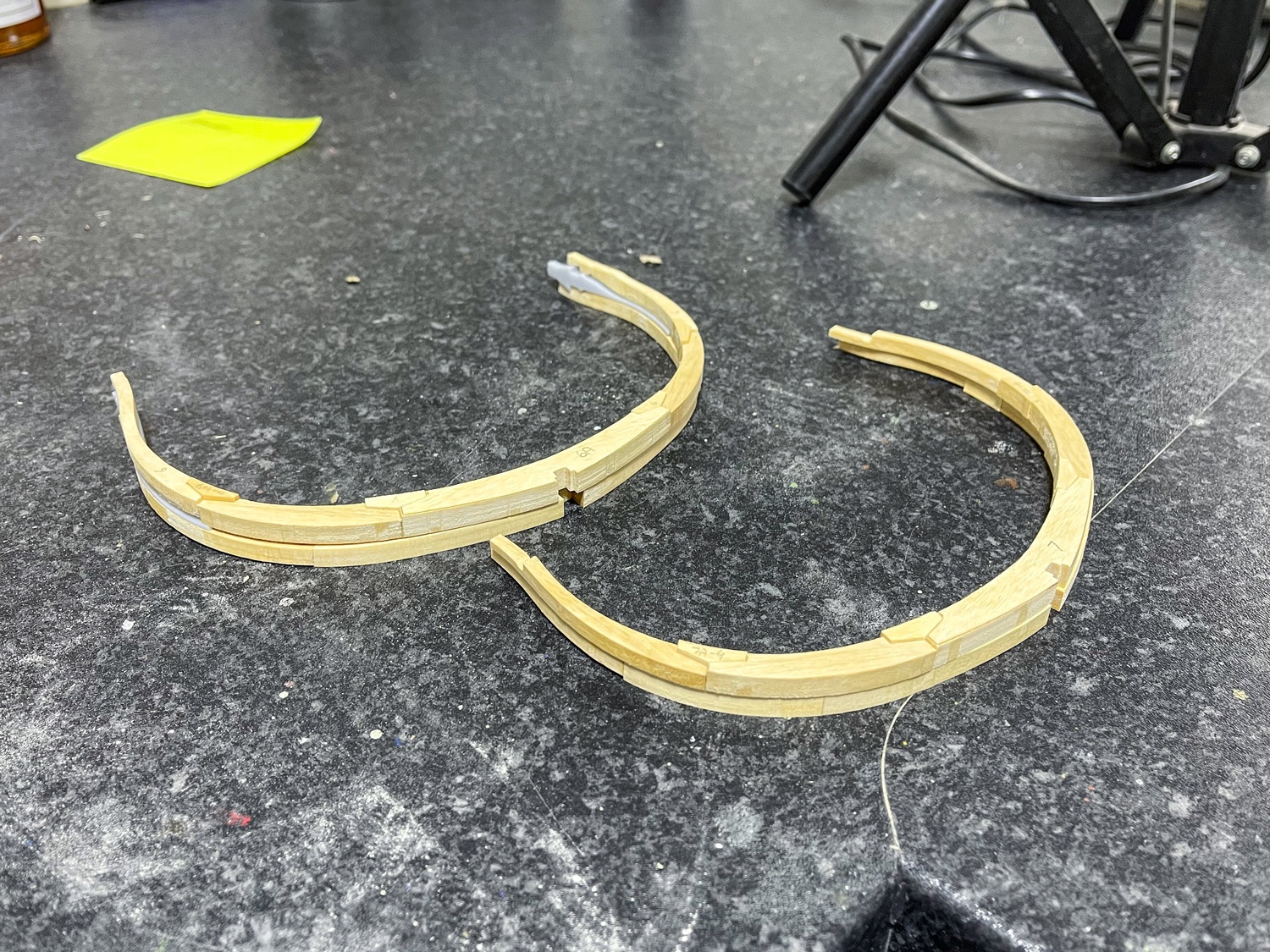
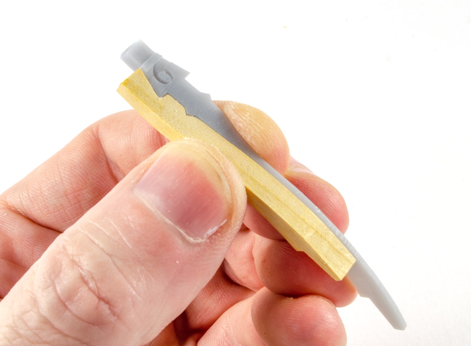
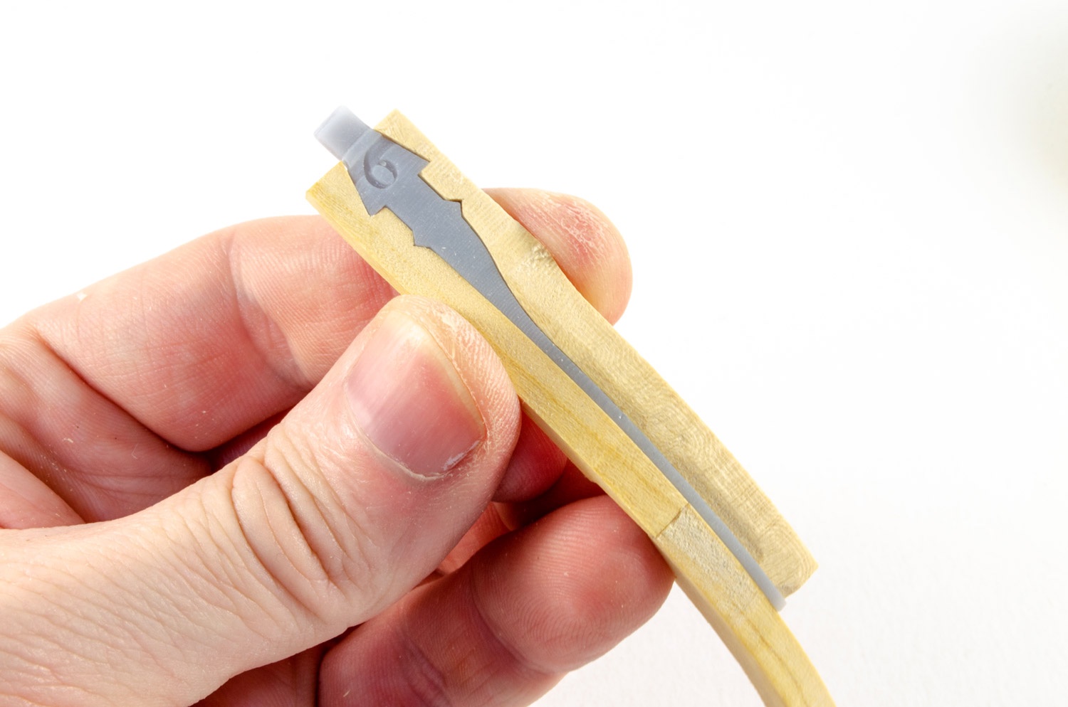
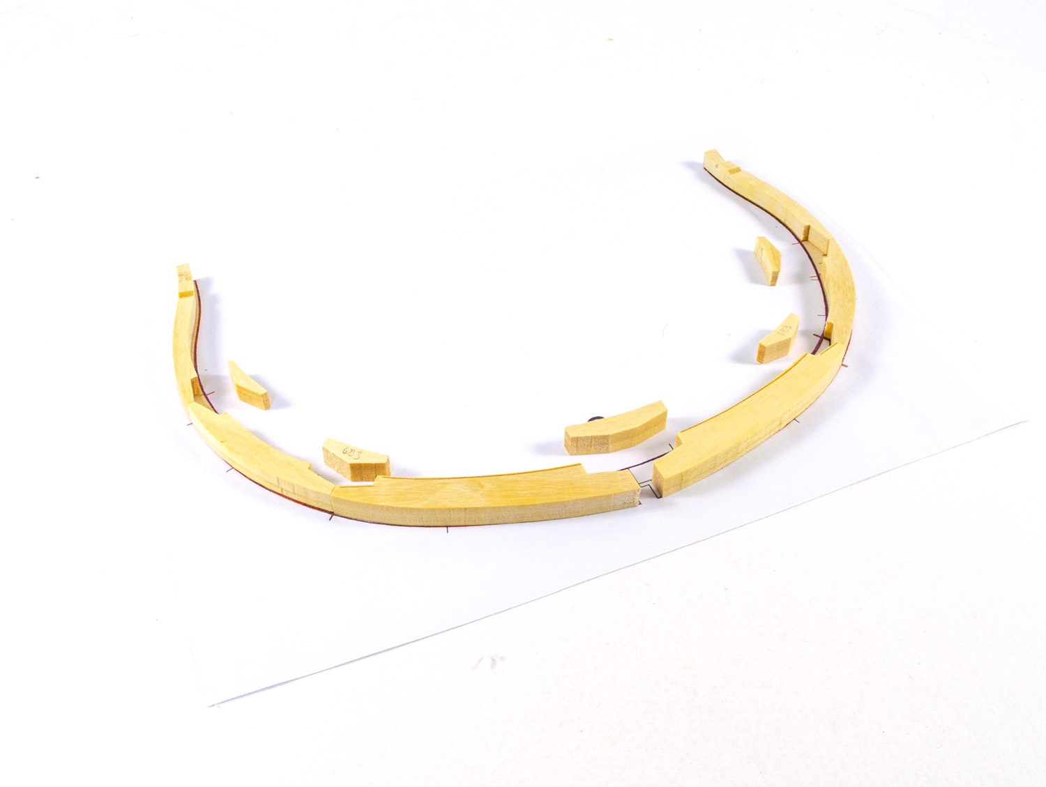
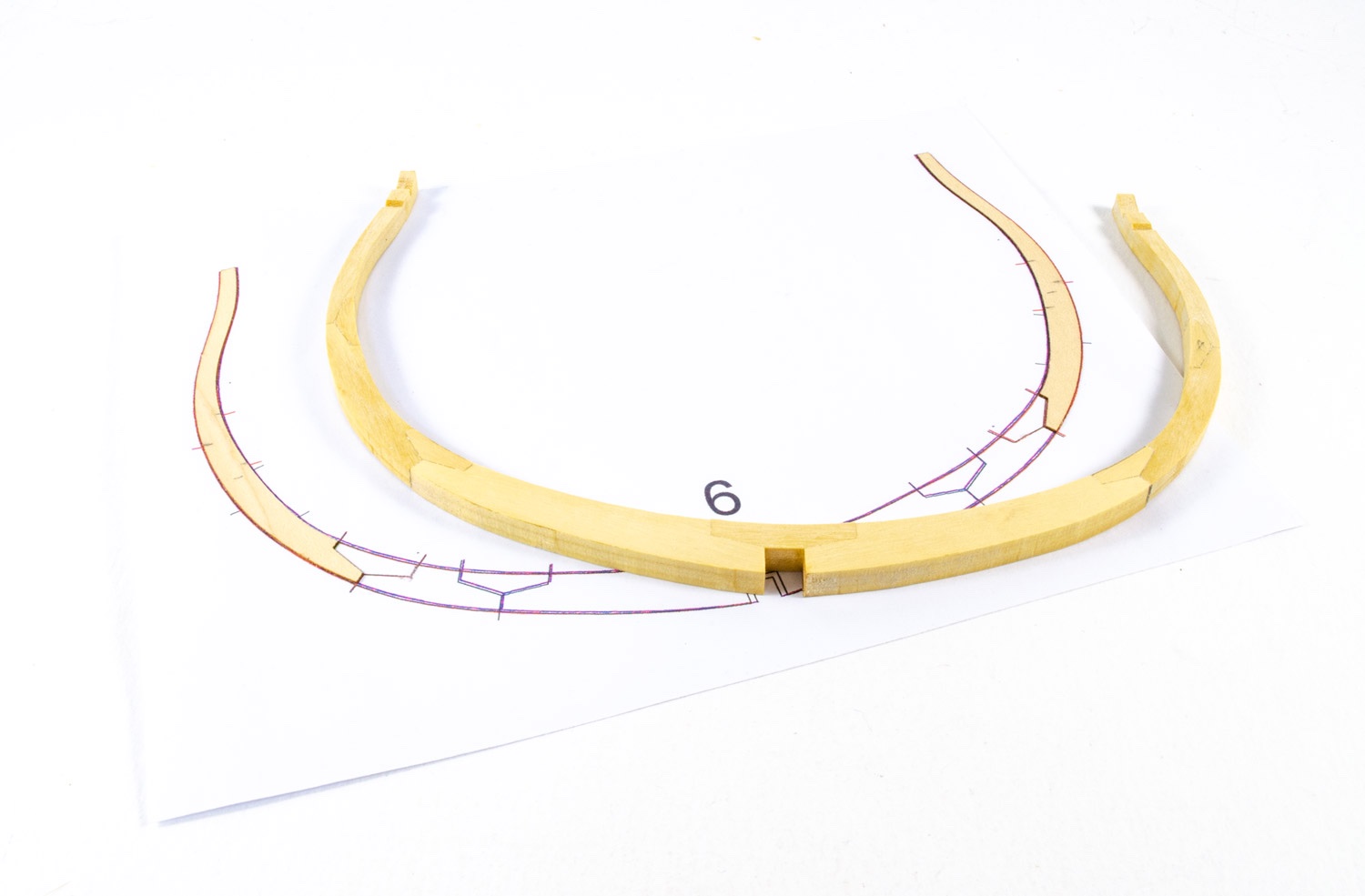
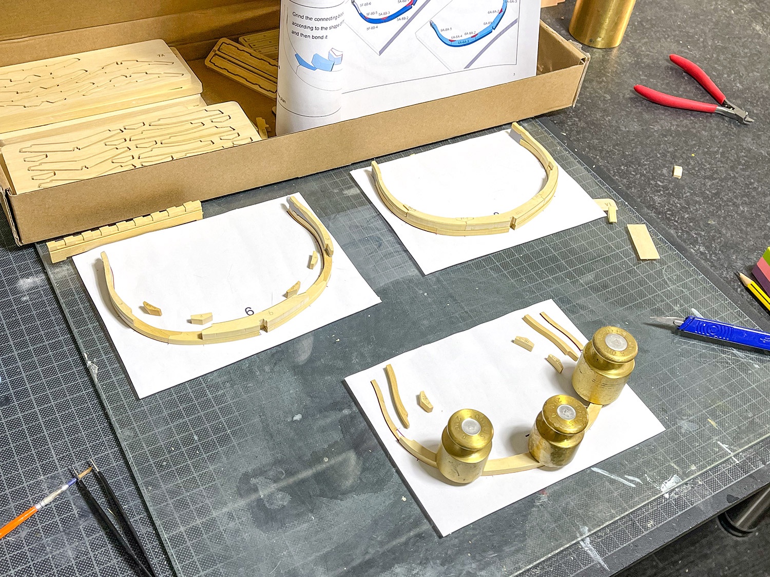
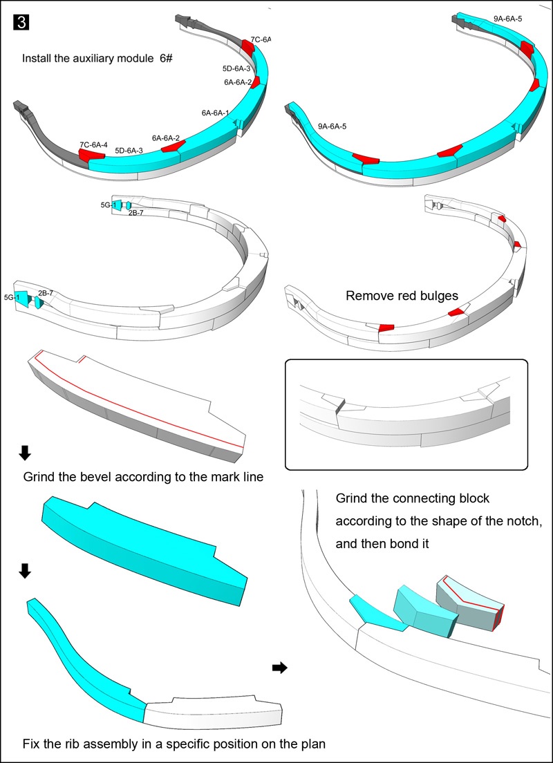
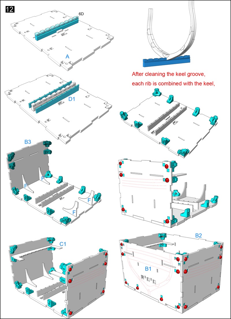
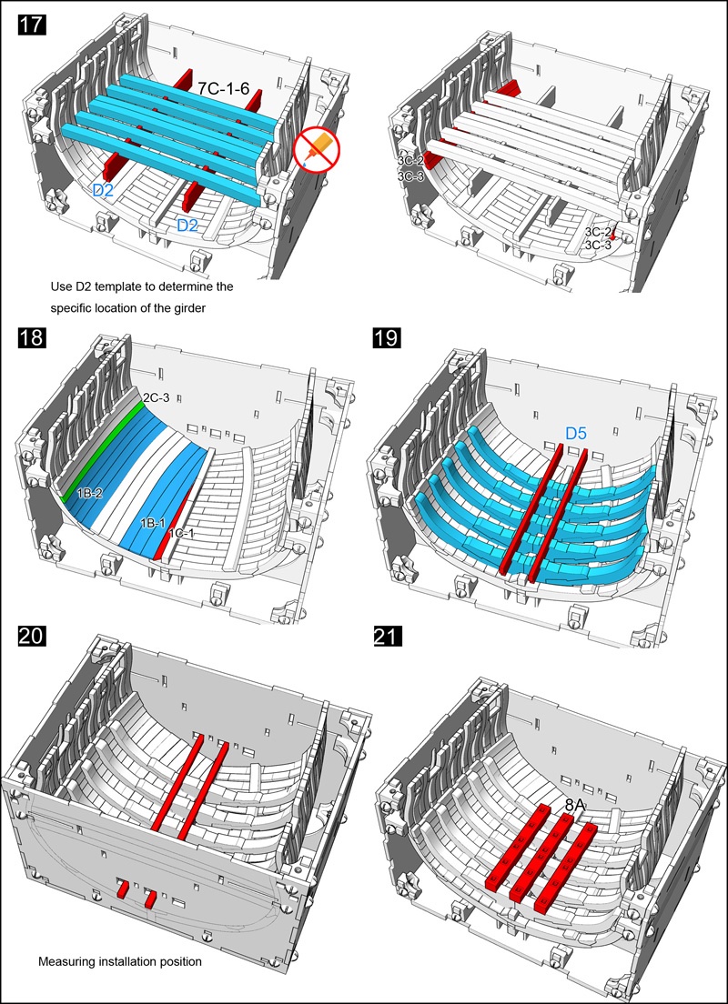
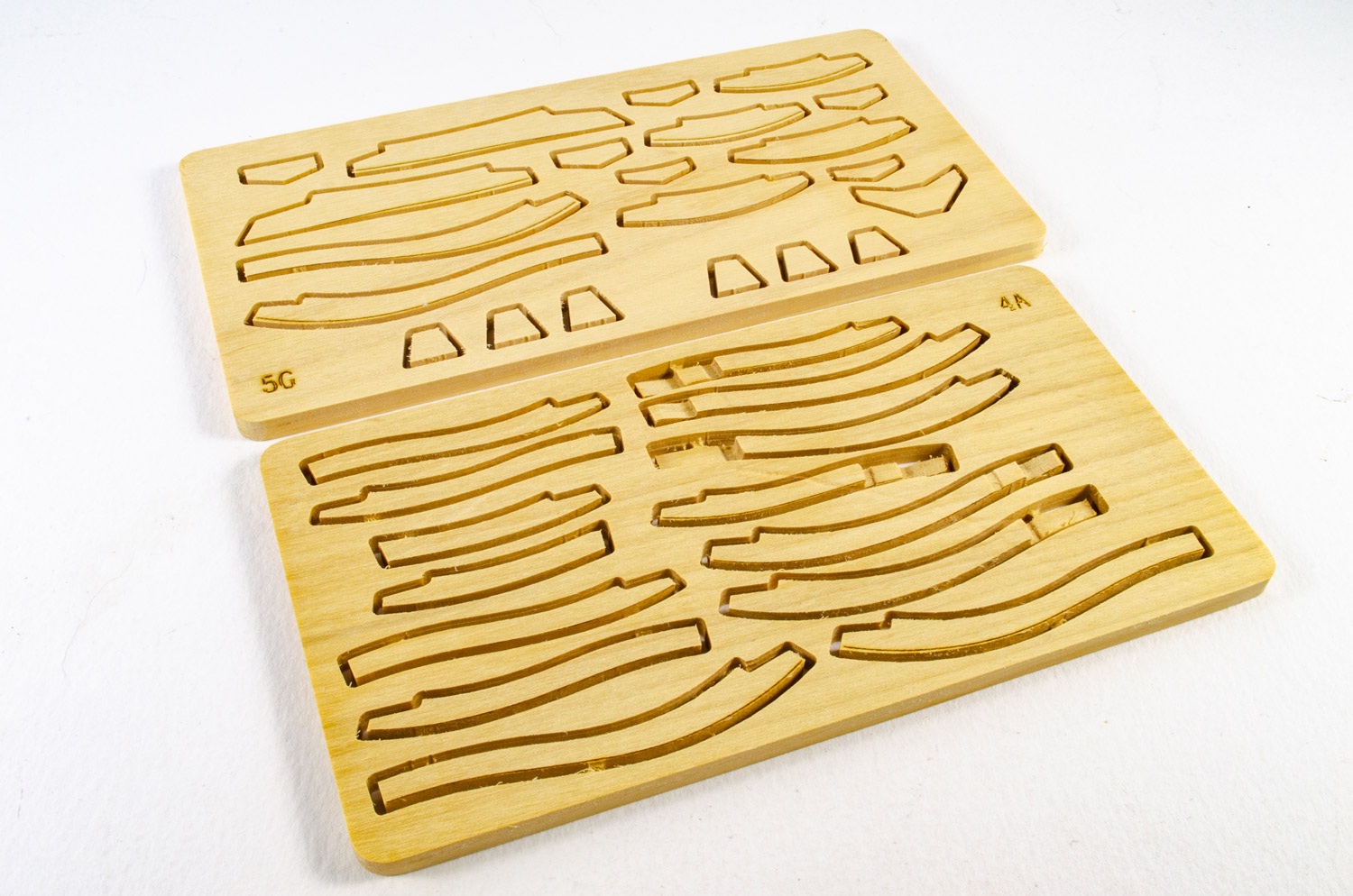
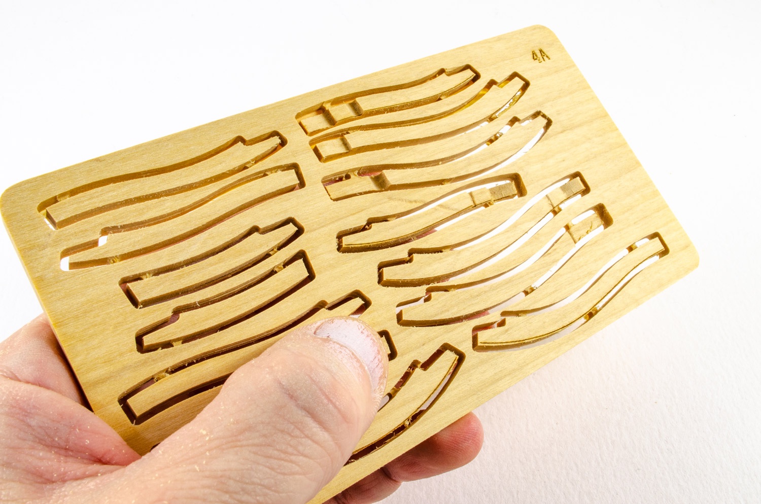
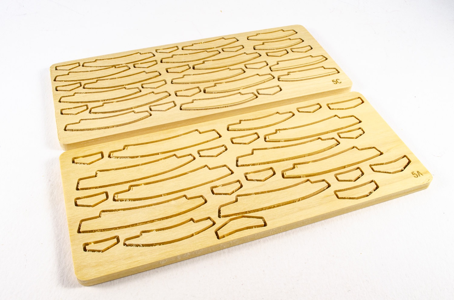
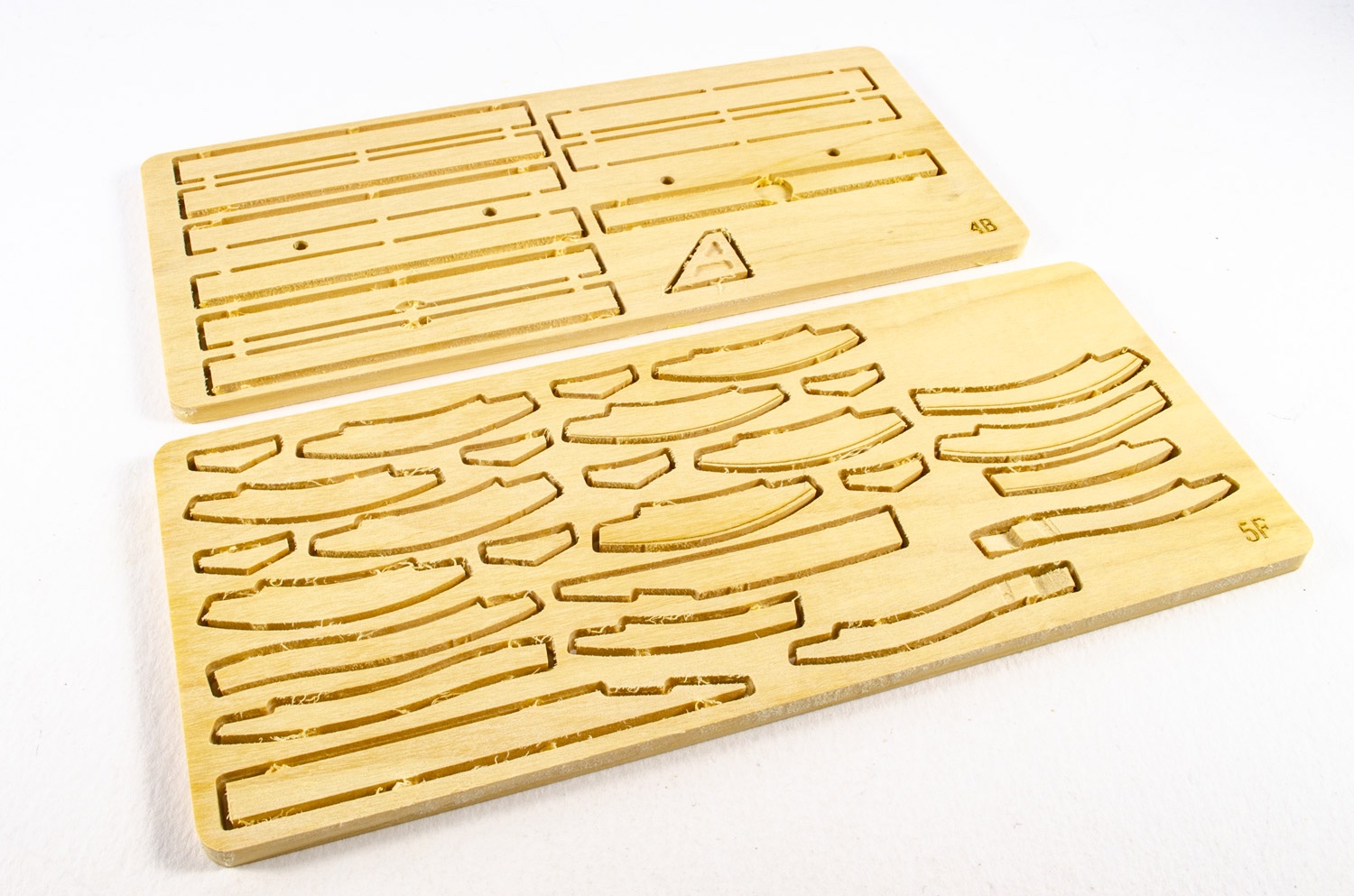
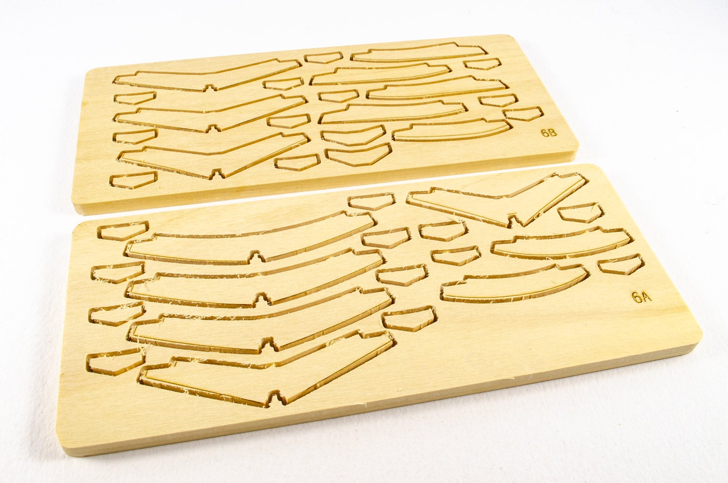
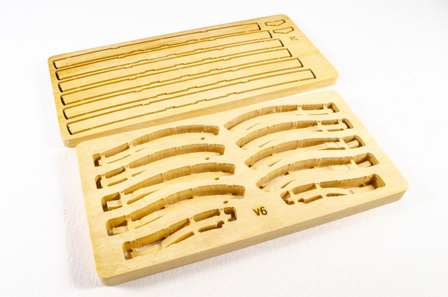
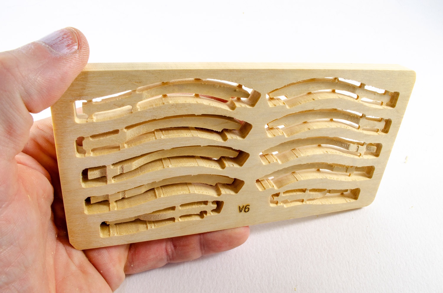
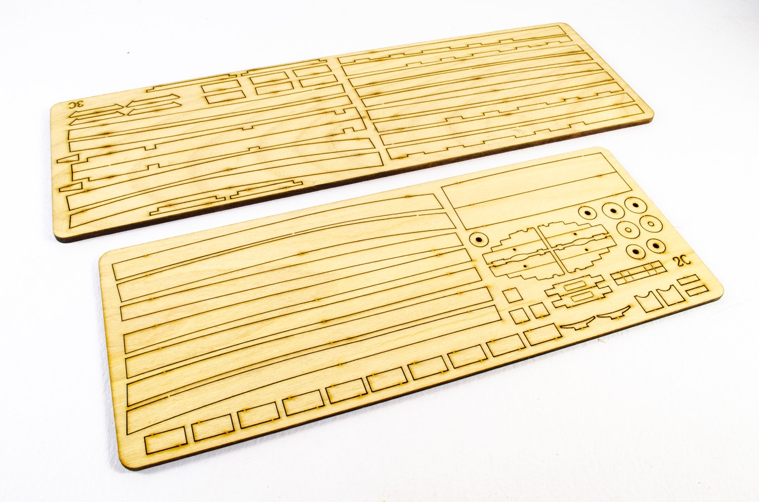
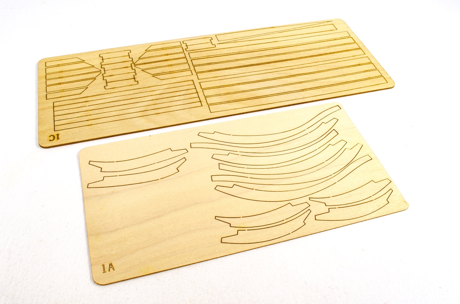
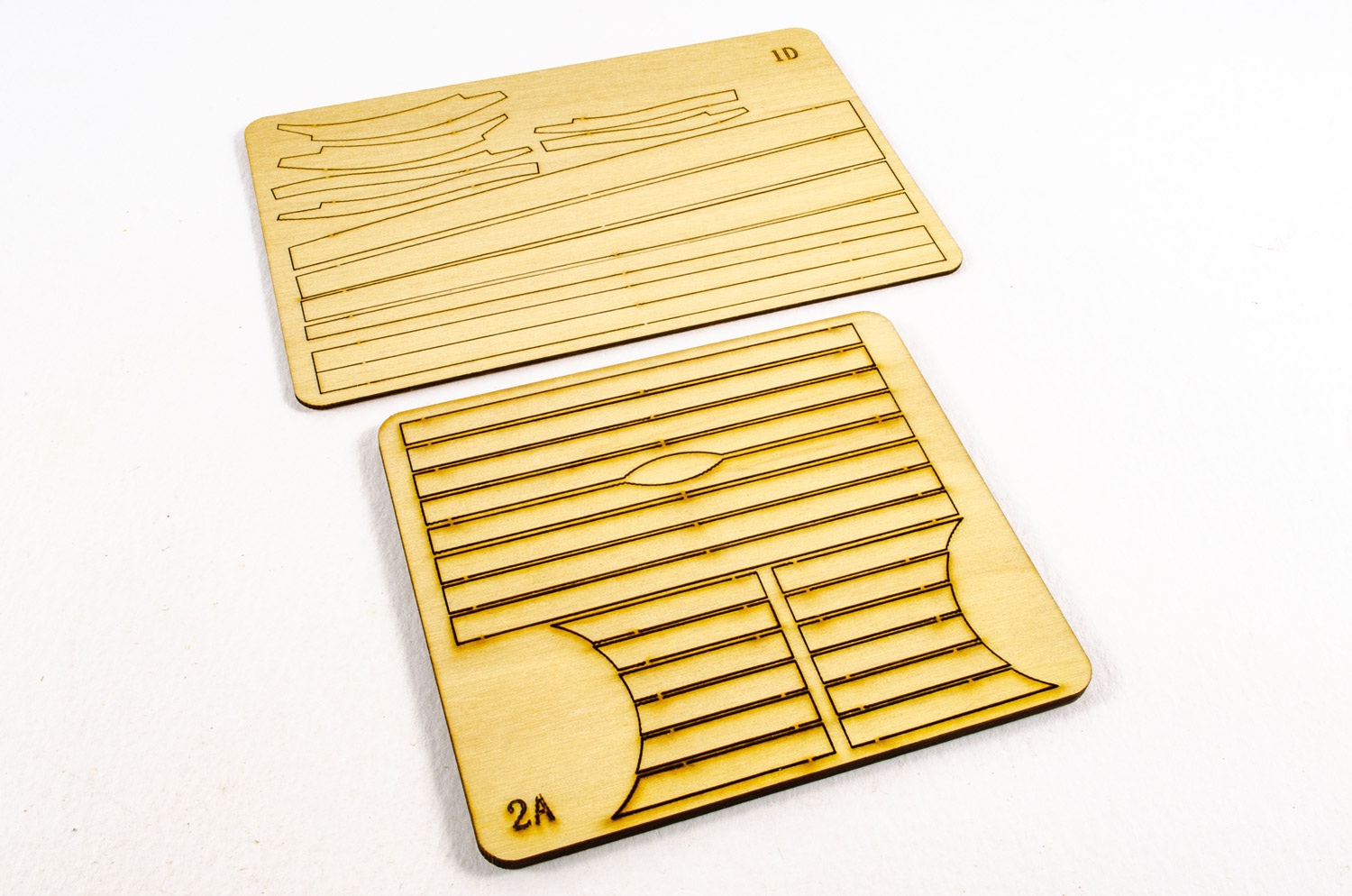
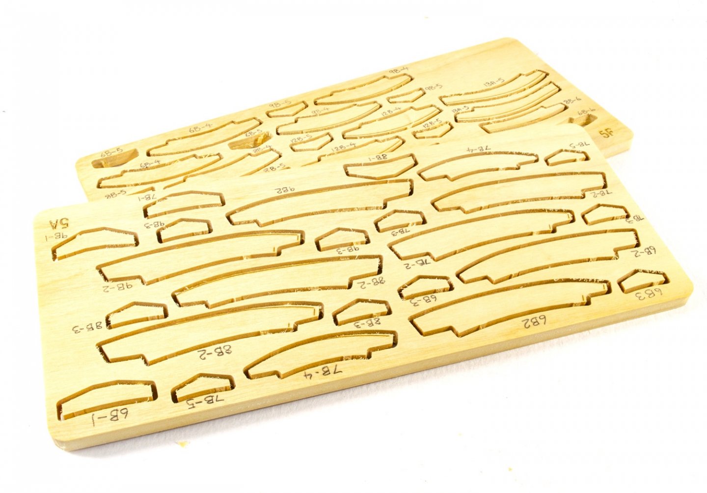
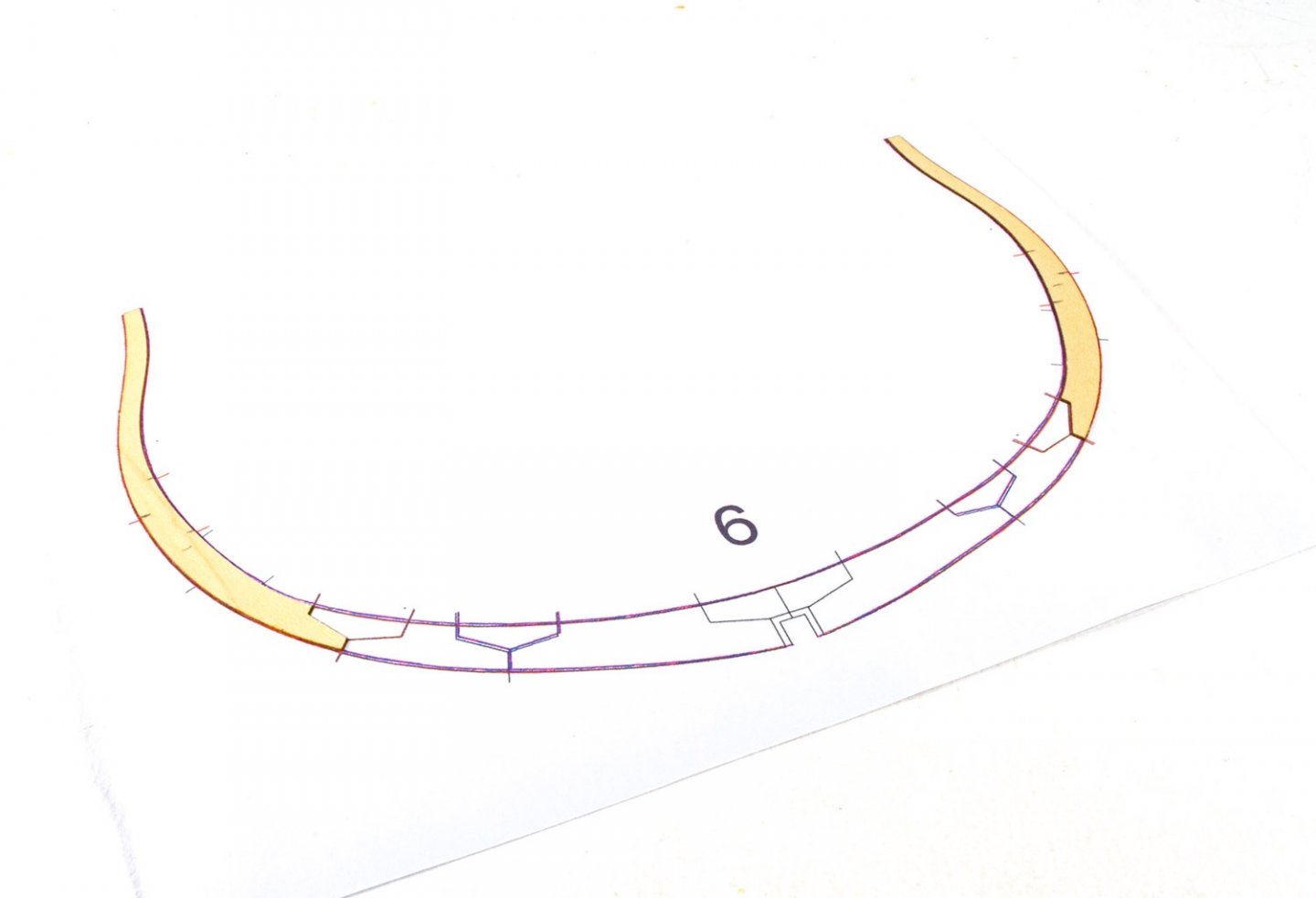
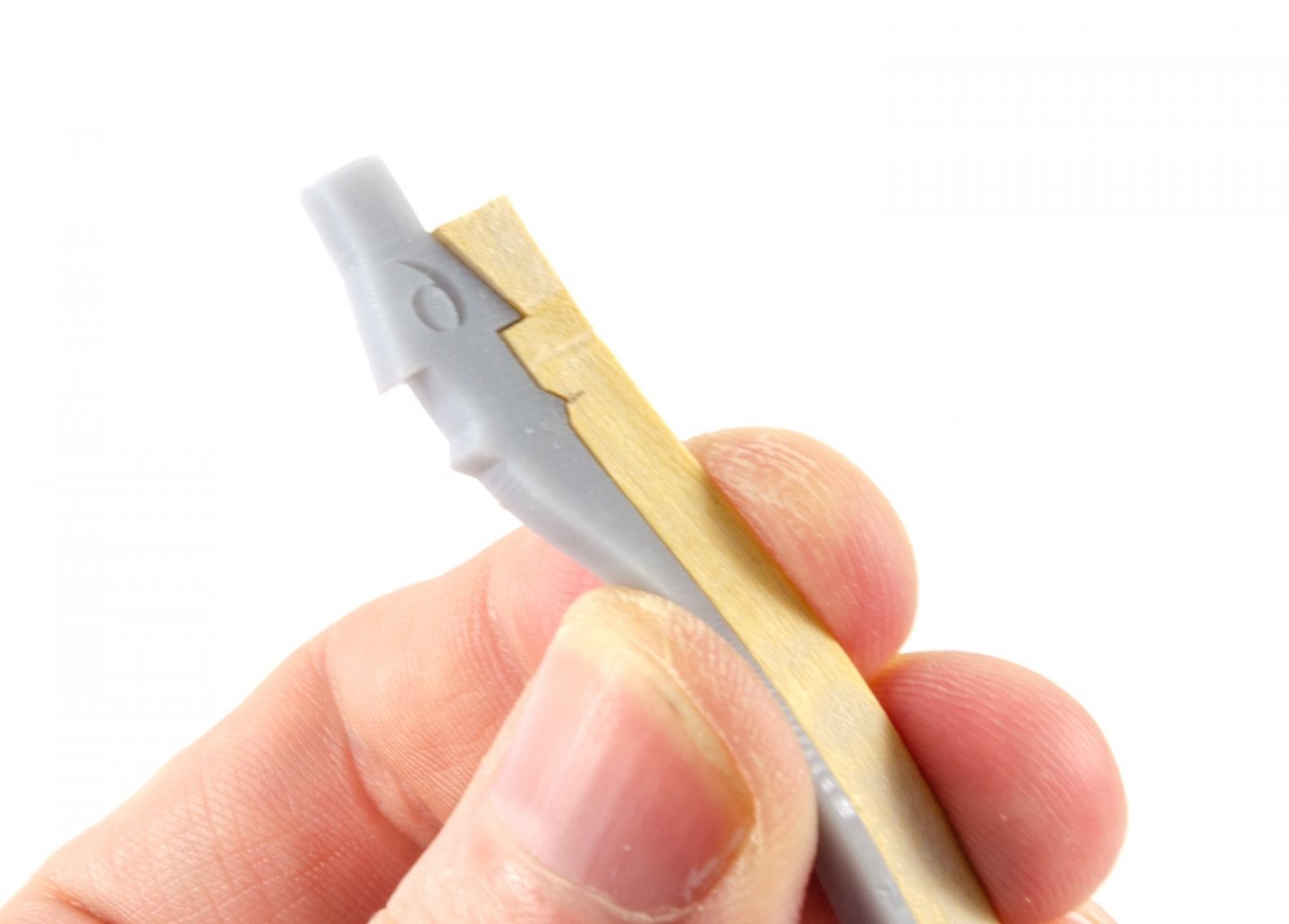
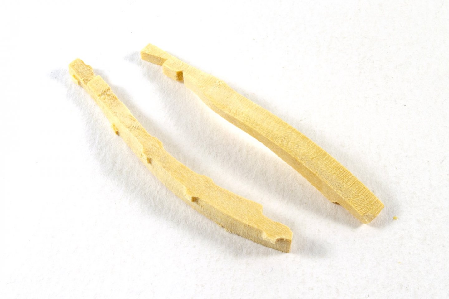
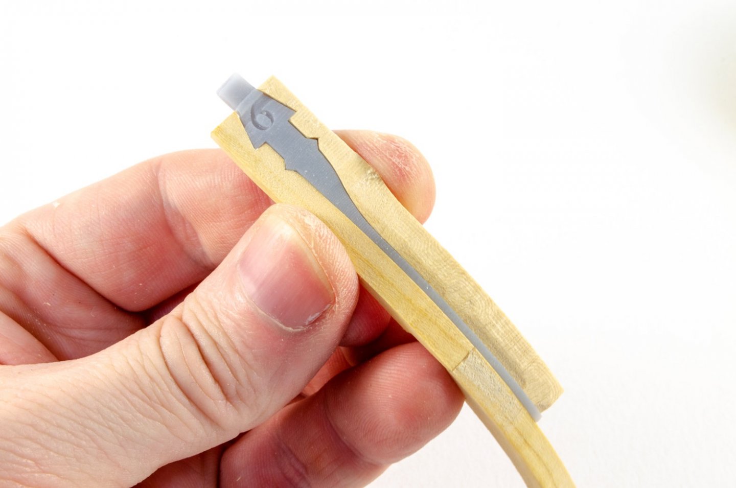
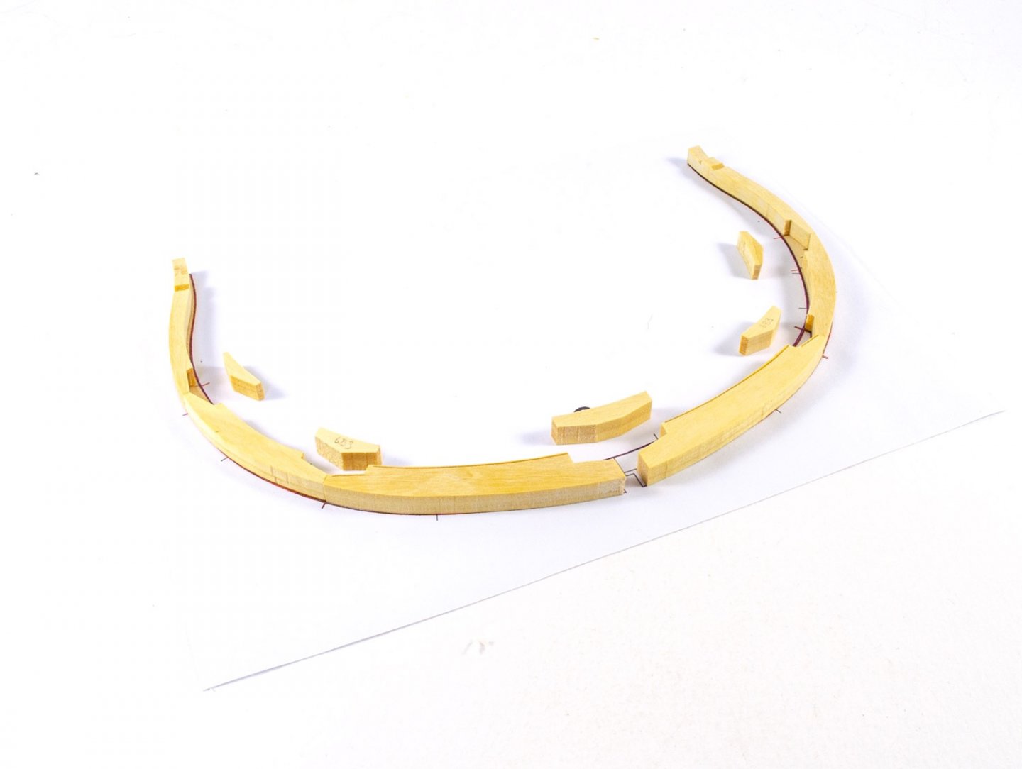
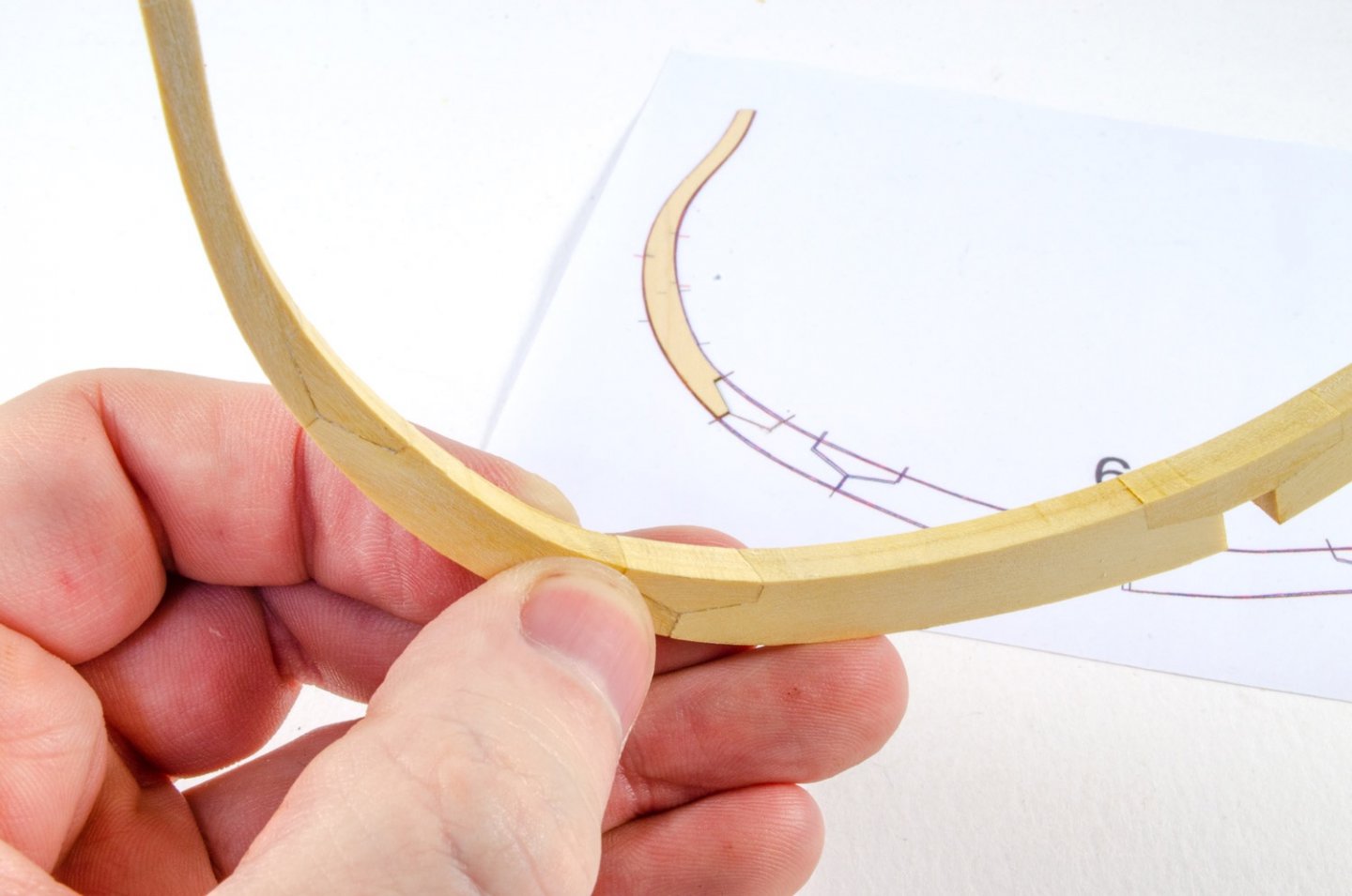
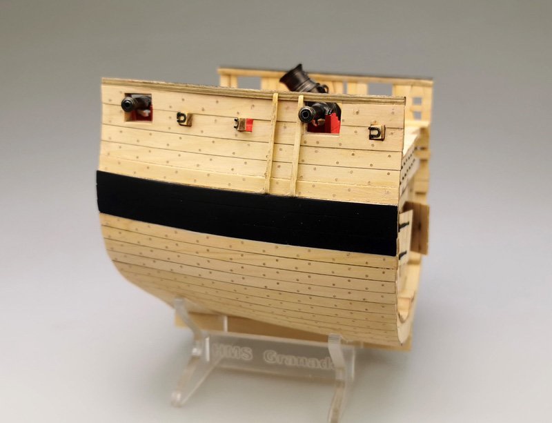
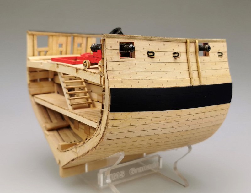
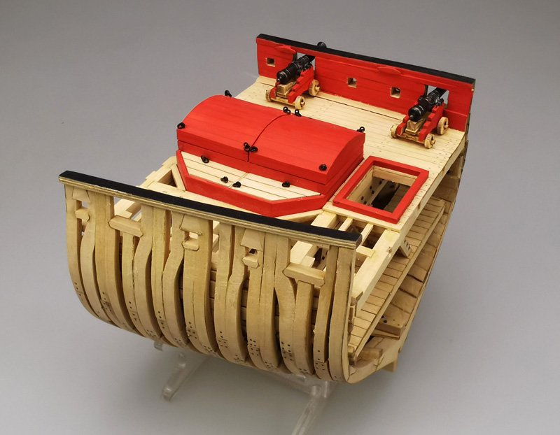
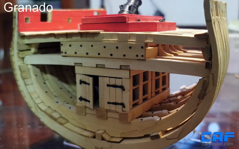
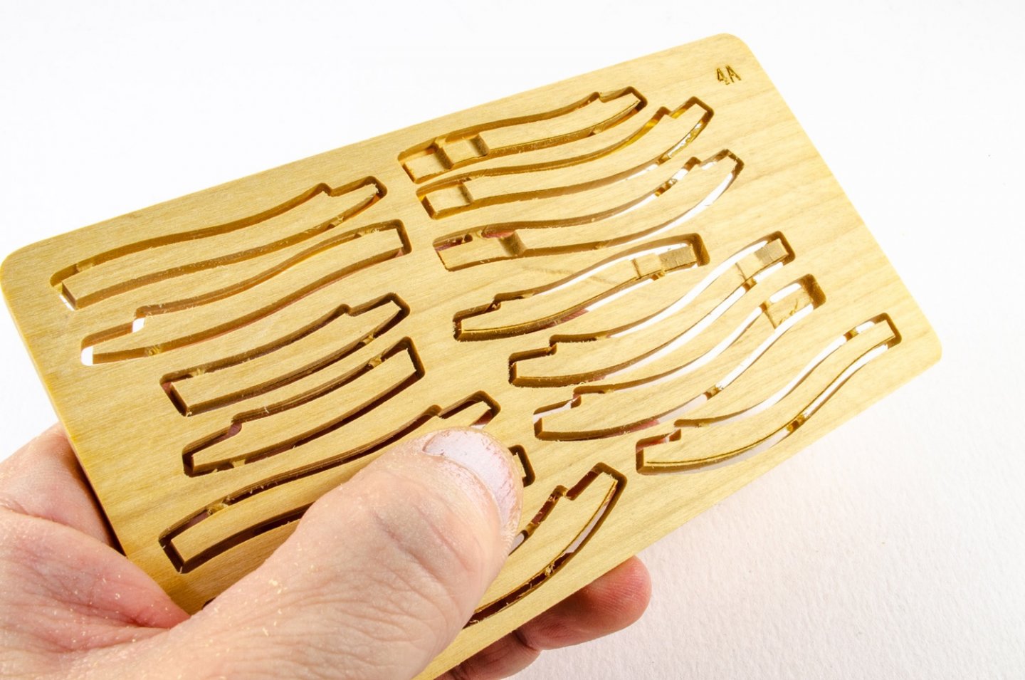
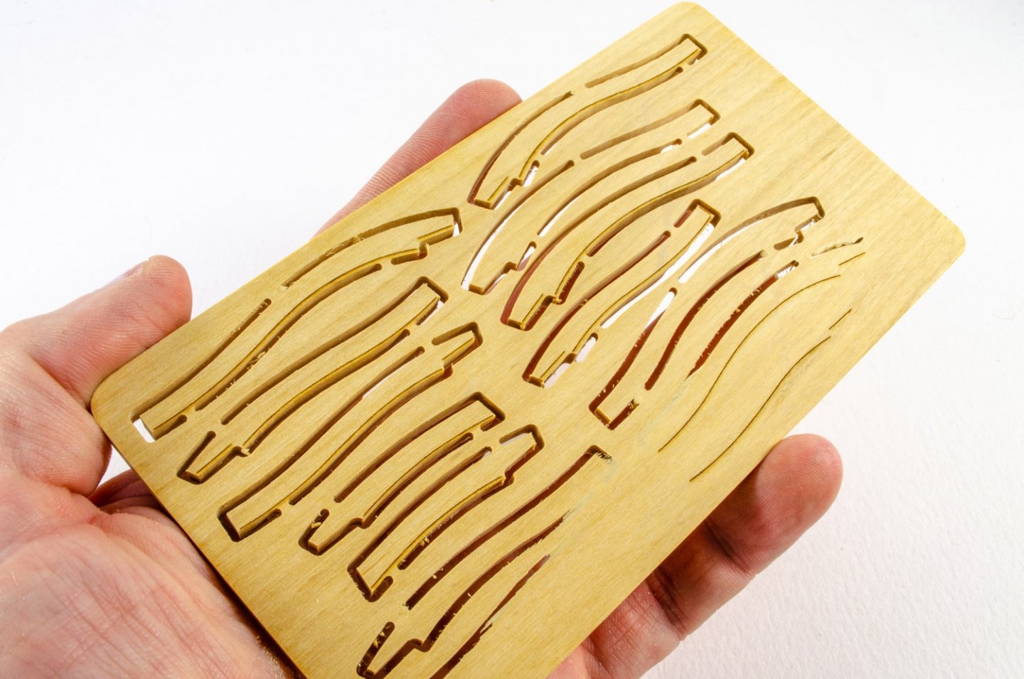
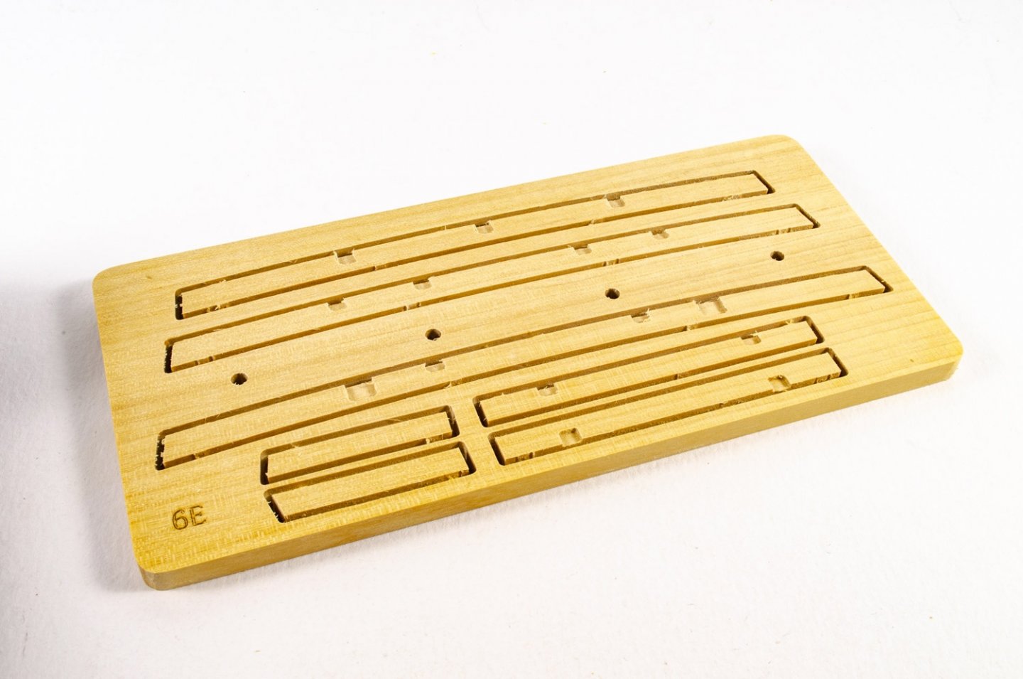
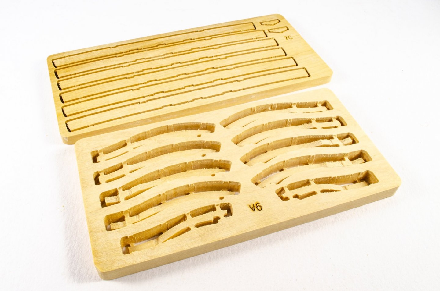
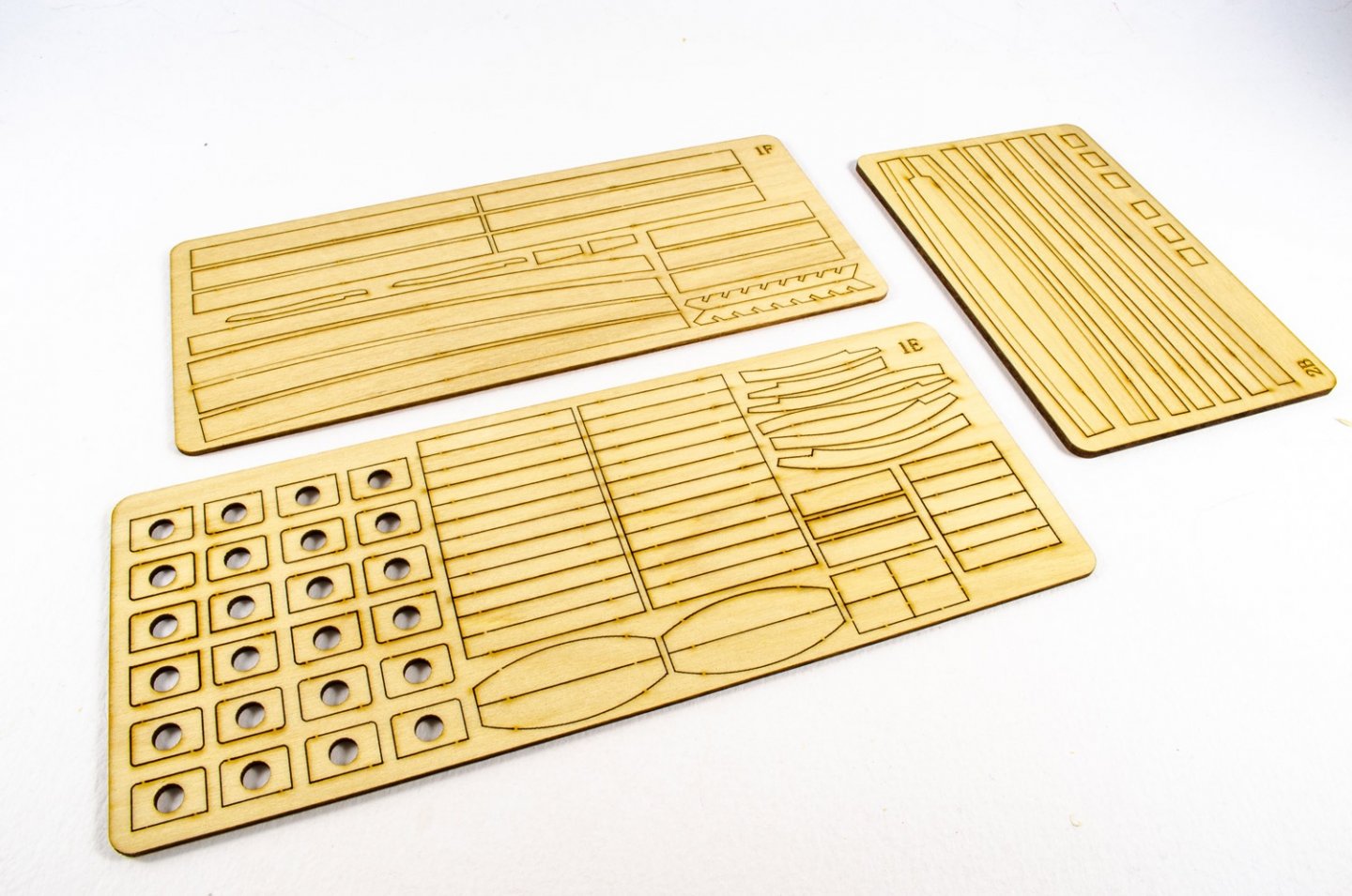
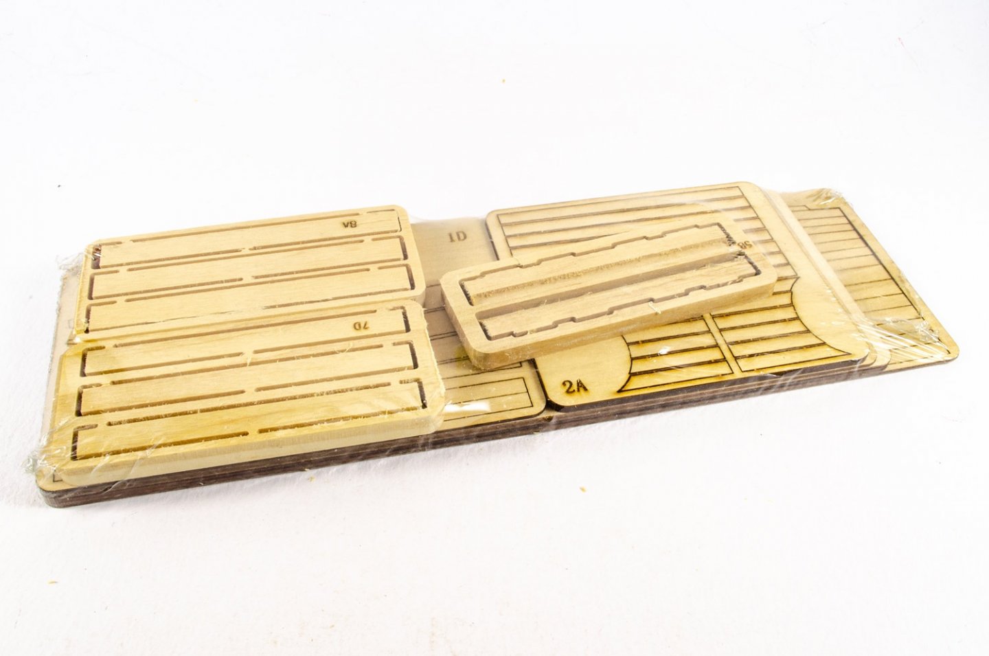
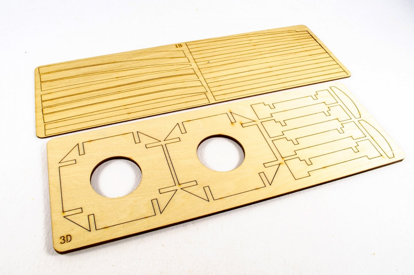
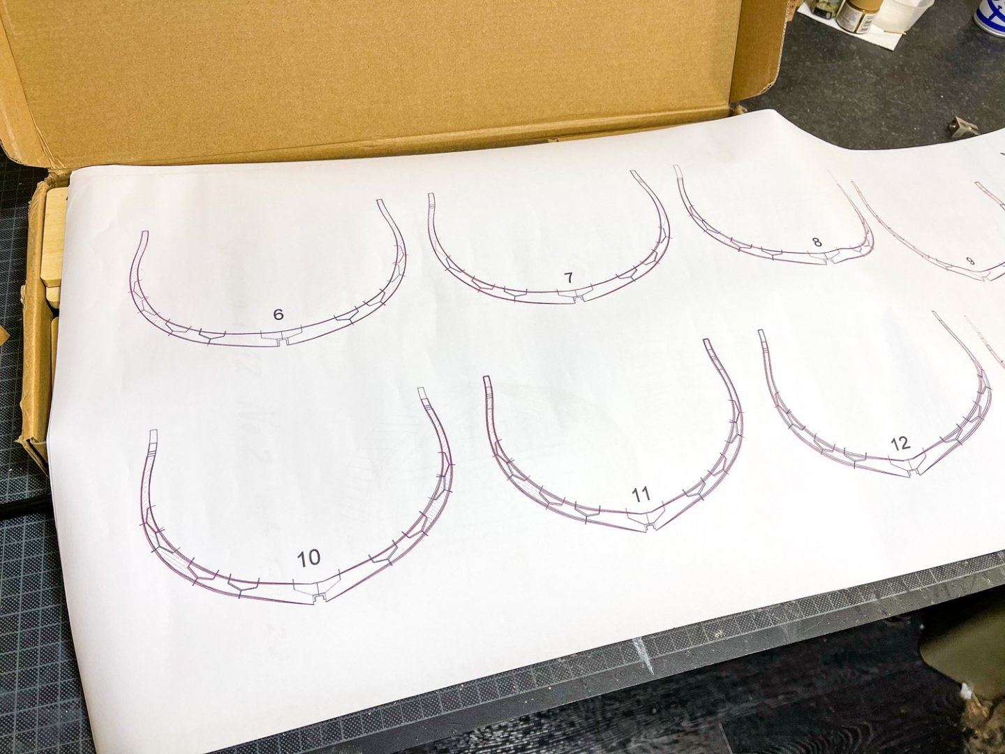
Ok, I've decided to dump down the photos I've currently got on this one as FedEx has twice delayed my missing parts sheets. Please remember, I've never done a POF before, so this is definitely out of my comfort zone. If you see anything untoward, feel free to make suggestions. 😊 Not sure what timber is used in this kit, but it's very similar to boxwood that I've used in models many years ago, and also at school. It's reasonably yellow, quite hard and with a fine grain. All sheets in the kit really need to be numbered as per the parts plan in the rear of the manual. You definitely don't want to mix any of these parts up. Parts removal is also very easy, with some cleanup required on tabs. A small number of the machined surfaces also look a little 'fluffy'. Until everything is sanded, I found that a simple shave/scrape with a blade was sufficient enough to sort it. whoops! upside down numbers! I've started by building frames #6, 7 and 8, and for the moment, also the 'B' part of each of those frames, which is the rear of each double frame (towards the stern, of course). Before any building, there are some filler parts which need to be glued to the plans (all frames except #14), so this was done from the outset. A hatched area on each frame drawing indicates where these fit. Also refer to my post about corrections to plans for fillers on #7 and #8 frames. A number of the top timbers are CNC-machined to shape, on both parts A & B of some frames. These just need to be snipped out from the sheet 9A and then cleaned up. Temporary resin inserts are provided to add some gaps/spaces between some frame A & B sided, and the CNC parts need to have their 'V' notches properly cut into place so accommodate the resin spacers. Each set of spacers is also numbered specific to the frame you are working on. All parts of each frame B (in turn) are removed from the various sheets and cleaned up. As this stuff is CNC routed, all internal corners are rounded and will need to be squared off. I used a scalpel for this and it only takes a minute or so per joint. For gluing, I use Evo-Stick formula wood glue, and I also bevelled the timber joint as per plan (and the chocks).....BUT, it took me ages to make a single joint and to get it to fit more or less gap free. I've since found these joints are NOT angled/bevelled and should be perpendicular to the frame....no angled chocks either! I can't tell you how pleased that made me. There are a few laser engraved marks to show bevelling of these, so I'm just ignoring them. Only Frame 6B has them on mine, and the others won't. NOTE: When assembling, note the bevelling lines on the timbers, and that the red lines on the plan are for the REARMOST extremity of each frame 'B'. Frame work so far: Whilst waiting for my parts to arrive vis FedEx, I assembled the two keel parts. Again, there is a certain amount of cleaning up to do, but I think the results look quite neat. Back to the cave...


- 16 replies
-
- 24
-
-
Proud owner of a Dremmel drill stand
James H replied to DaveBaxt's topic in Modeling tools and Workshop Equipment
I've got one of these and it's sat idle for years. I was thinking that it could be used as a drum sander is the Dremel is lowered close to the table. I'm in need of something like that for sanding the inside of my Granado frames/chocks. Would that be a reliable use of this press? -
Hi all, I'm actually waiting on a couple of small sheets of parts from CAF, and those should be here pretty soon, courier dependent. The kit itself landed last week in under 7 days from China, via TNT/FedEx. Pretty quick for these times we currently live in. If you haven't already checked out my review for this kit, please do so here: I still need to dump my photos from camera yet, and I'll wait until I have the first double frame complete. Give me a couple of days or so Jim
-
kit review 1:48 HMS Granado ‘Cross Section’
James H replied to James H's topic in REVIEWS: Model kits
Cheers, I'll get this set up. -
kit review 1:48 HMS Granado ‘Cross Section’
James H replied to James H's topic in REVIEWS: Model kits
including me? -
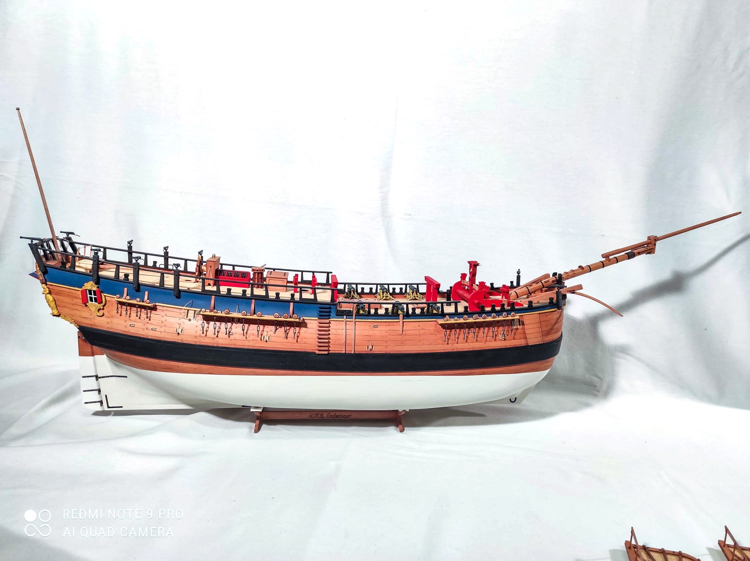
New 1:48 HMS Endeavour out later this year
James H replied to James H's topic in Wood ship model kits
I have three more photos of this yet unreleased Czech kit to show you. Release date has moved due to various reasons, but is now thought to be about May 2021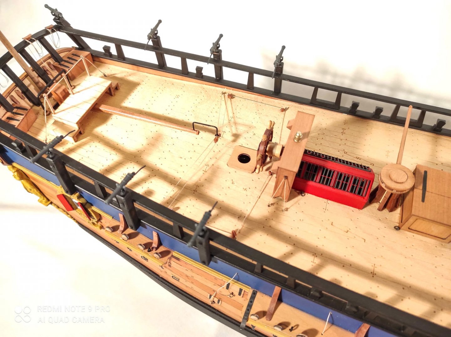

- 17 replies
-
- 12
-
-
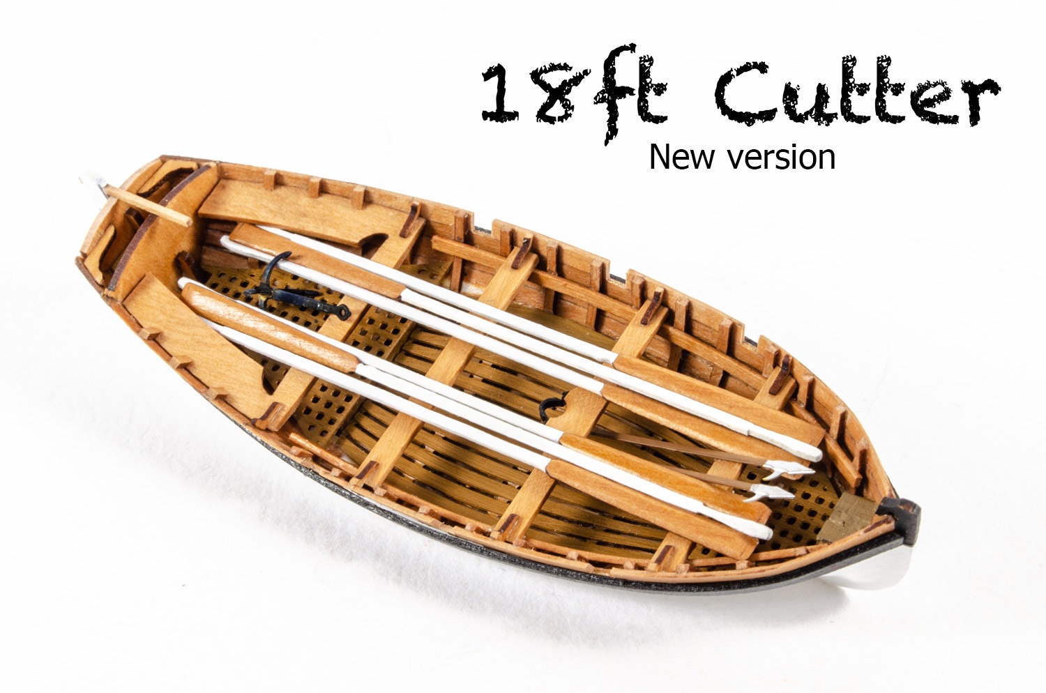
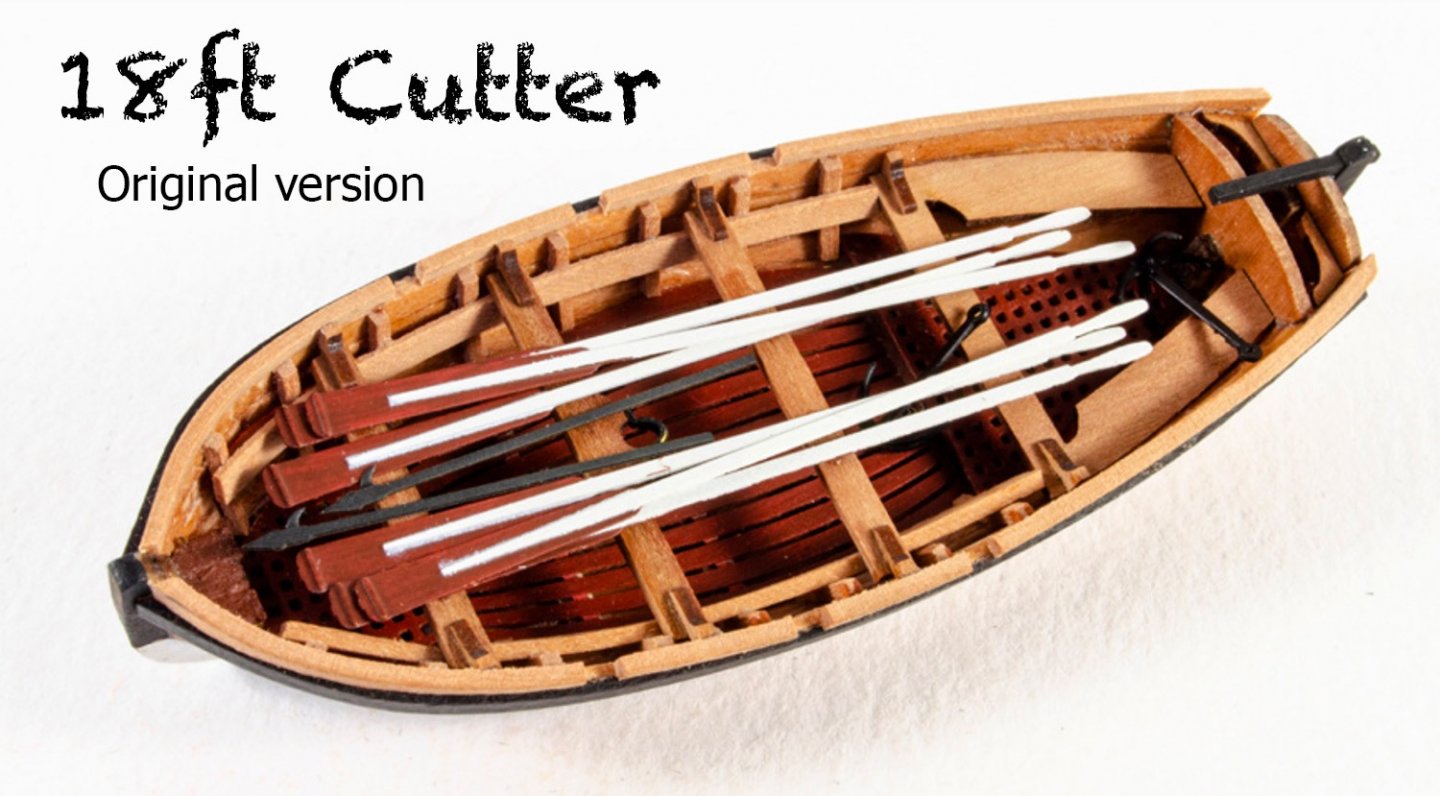
They both look real nice. That's a lovely write up too. Quite tempting to get out my MK Yawl while I'm waiting for some Granado parts to turn up. The reworked VM cutter was a lot nicer, in my opinion, to build than the one released first. The planking of the new one is also 0.6mm (laser cut, but not spiled). The finished result is a lot more refined than the original, and I built it with less swearing 😇

-
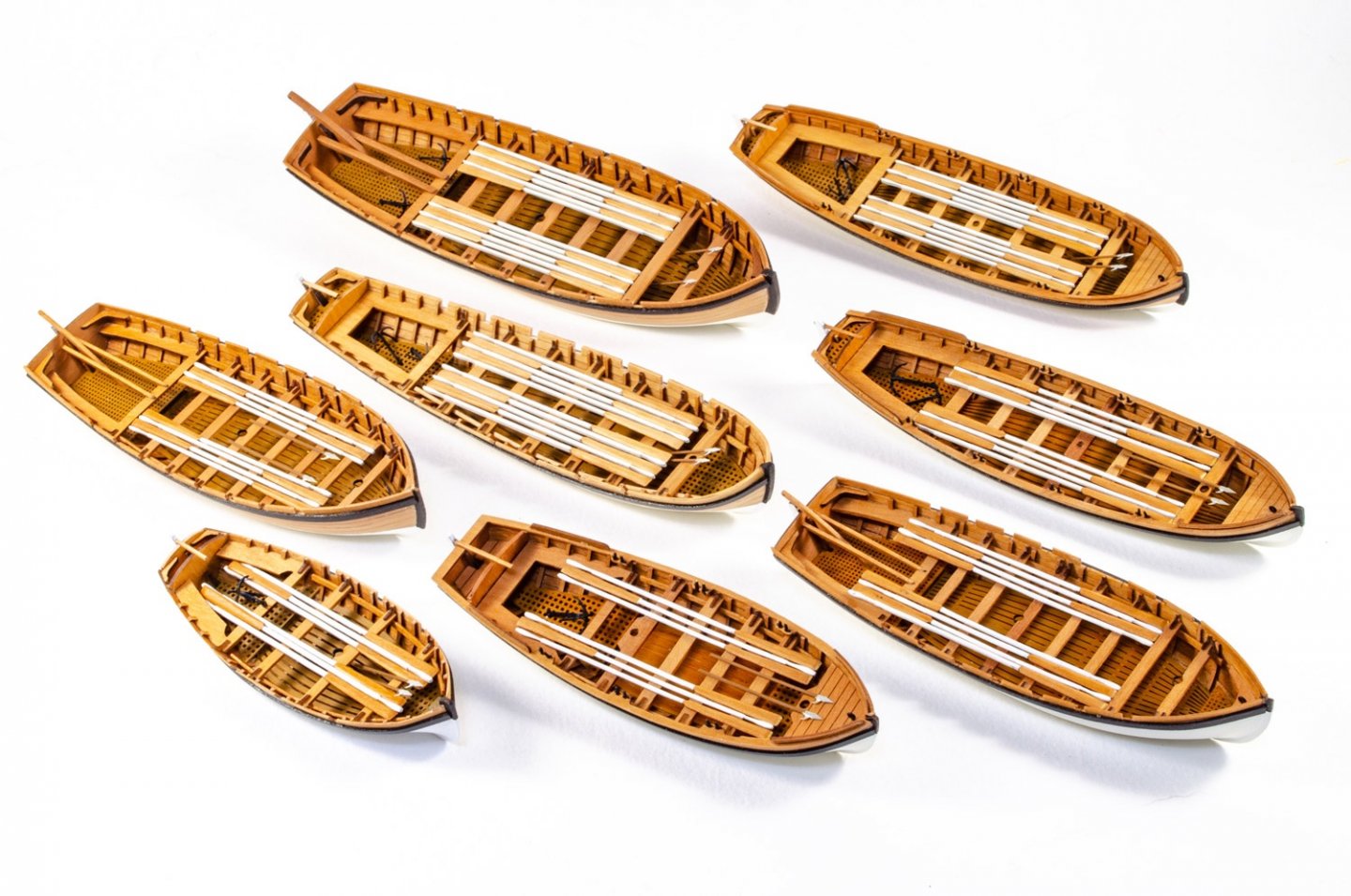
Haha! I would, but there is another valid reason for doing all these now... When the ships are being built, I can use these finished models, including the photo set, to save time. All I need to do is add the pics to the instructions and sit the boat straight on the deck/beam.
-
I use CA gel to do second planking and never had any issue whatsoever. Just use it sparingly and don't get clumsy with it. For some, it's almost like they don't like using a 'new fangled glue' and want to stick to the old stuff. Fair play, but there can be elements of snobbishness from those quarters too. Many other glues also create a chemical bond, so what's the problem? Should I boil down animal bones to make my own glue and use that instead? In the end, use whatever works for you. By the way, nice first post on CA. An excellent read.
-
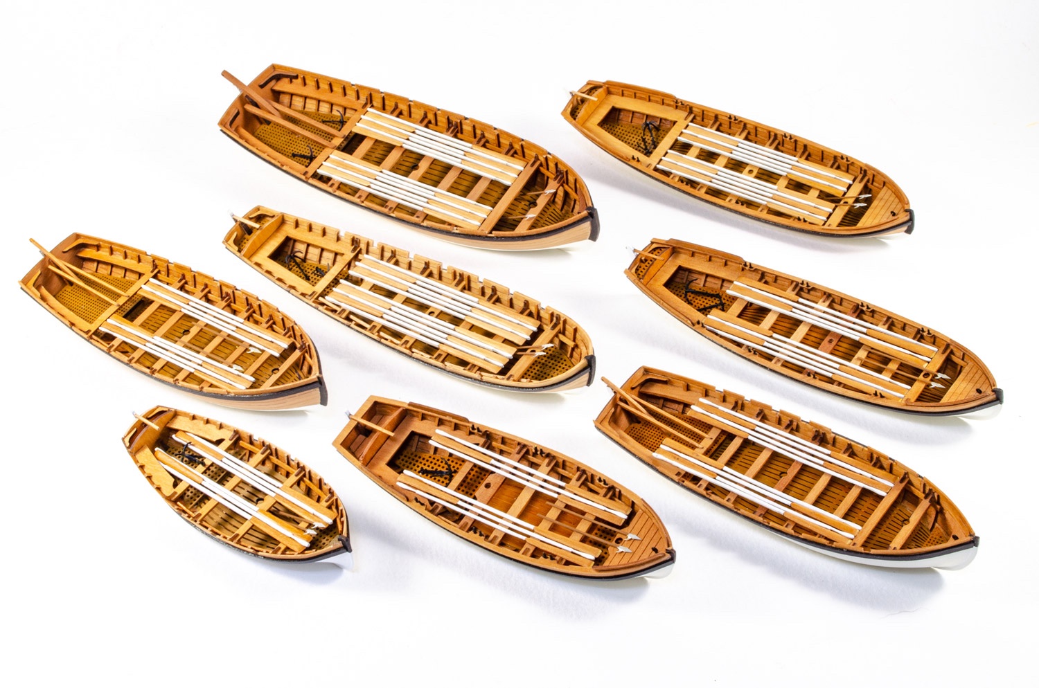
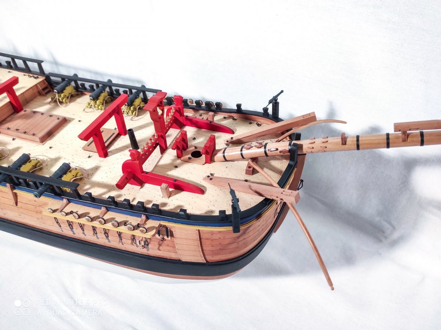
Since I've been doing a few photos on something else, I thought I'd take this one of the EIGHT ship's boats I've built for VM so far. I can almost do these with my eyes closed now. 😆
-
kit review 1:48 HMS Granado ‘Cross Section’
James H replied to James H's topic in REVIEWS: Model kits
Count me in 🤣 -
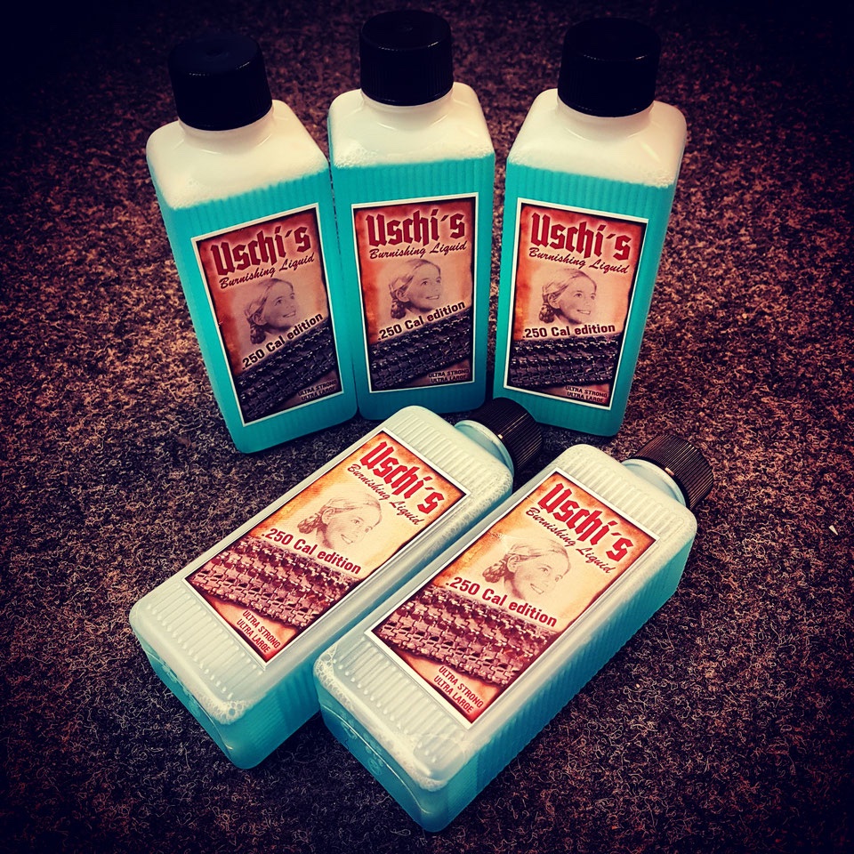
I'm using this to black my brass: https://www.uschivdr.com/shopping-categories/shop-chemicals/ €16.50 for 250ml.
-
She's so so pretty! Hope you'll add the completed photos to gallery.
- 436 replies
-
- 2
-
-
- vanguard models
- alert
- (and 1 more)
-
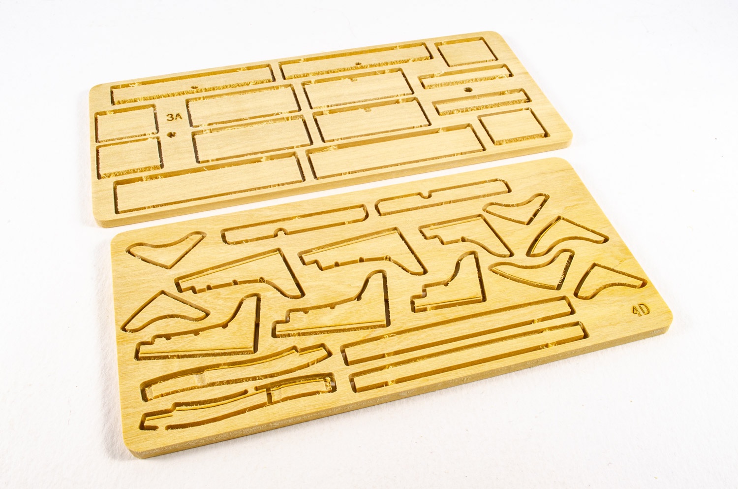
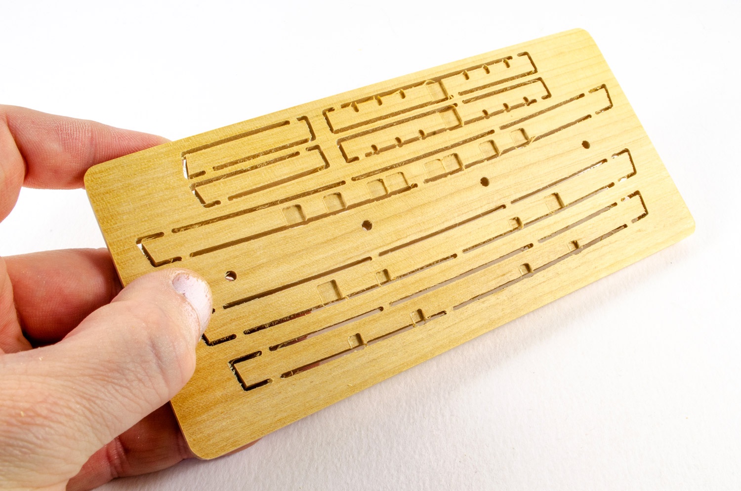
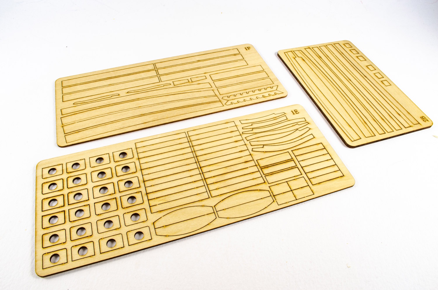
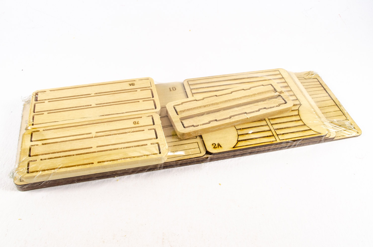
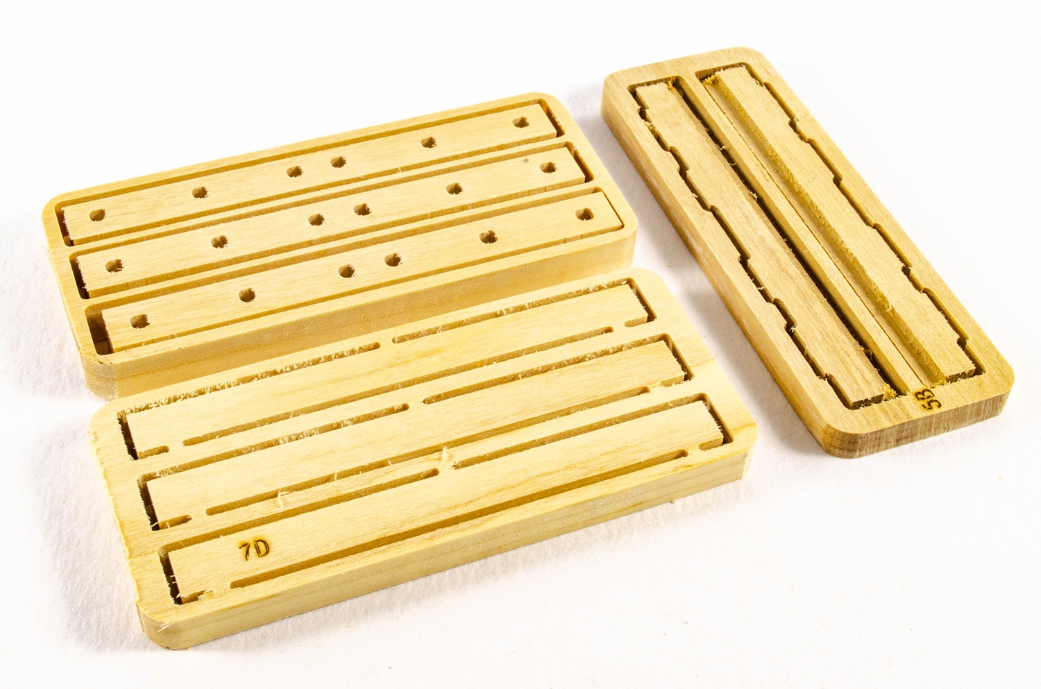
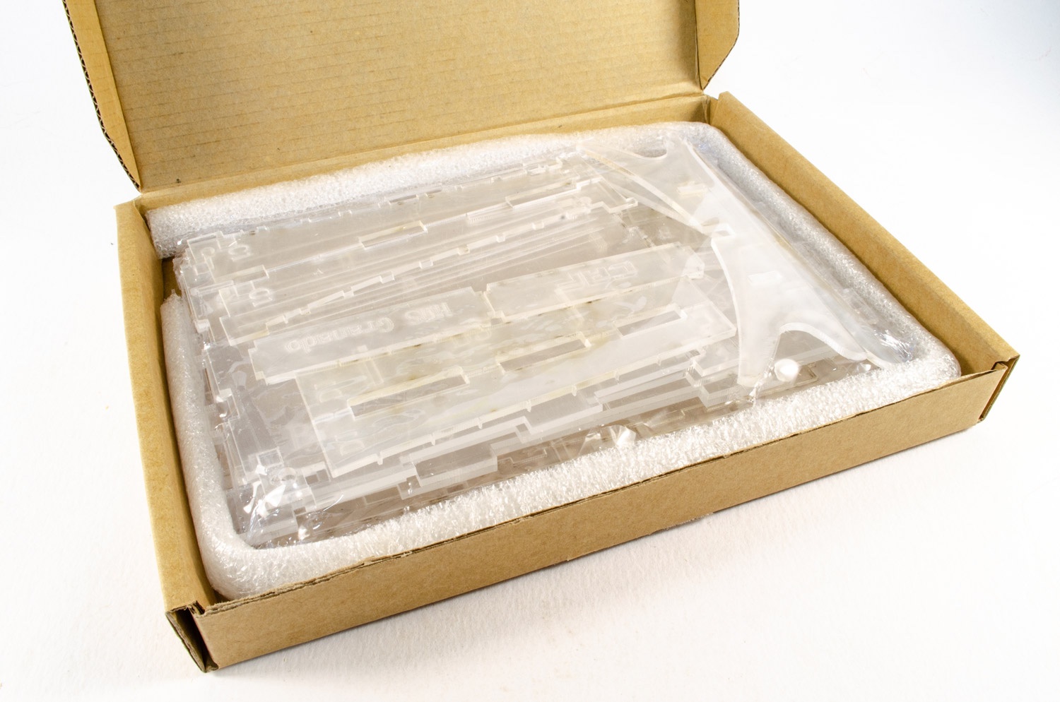
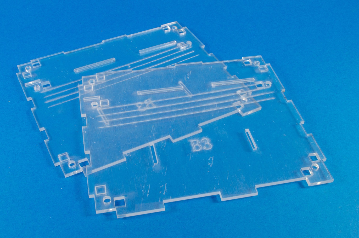
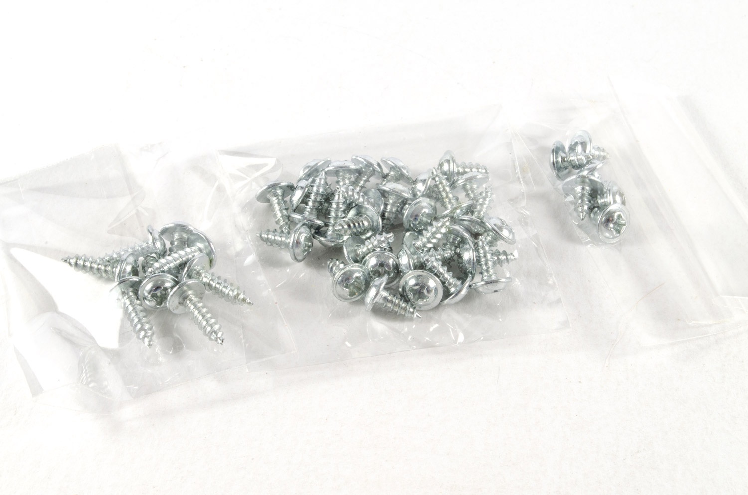
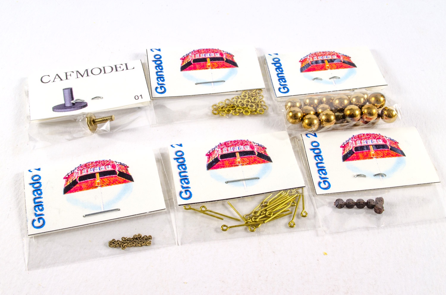
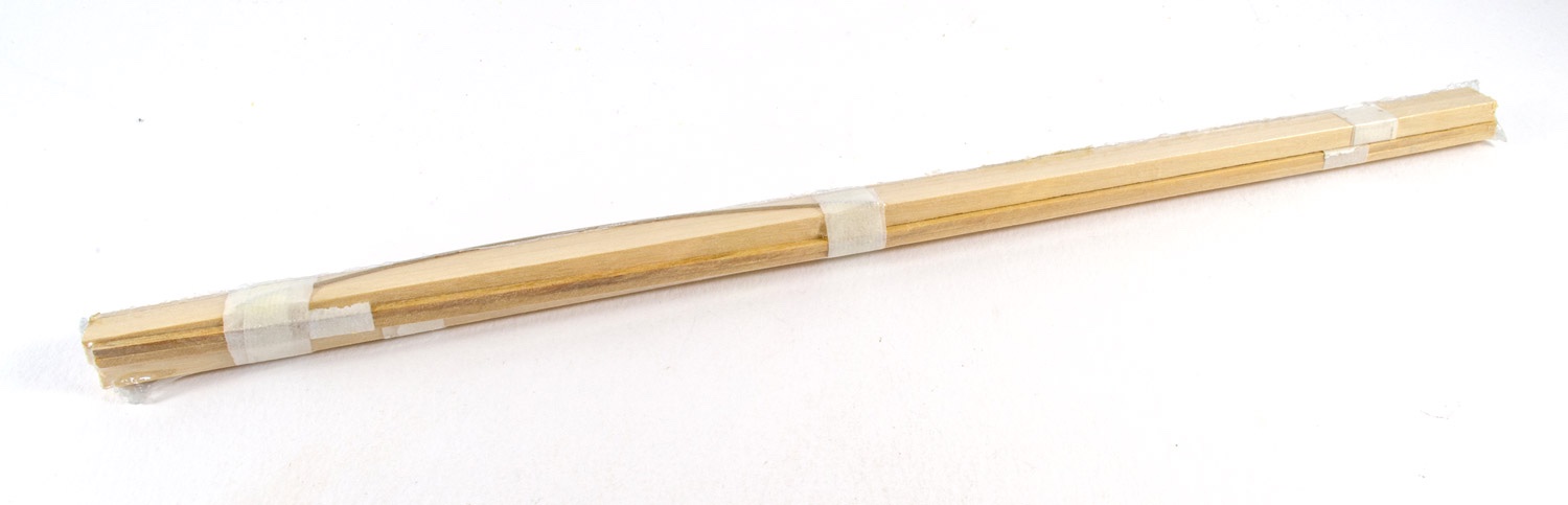
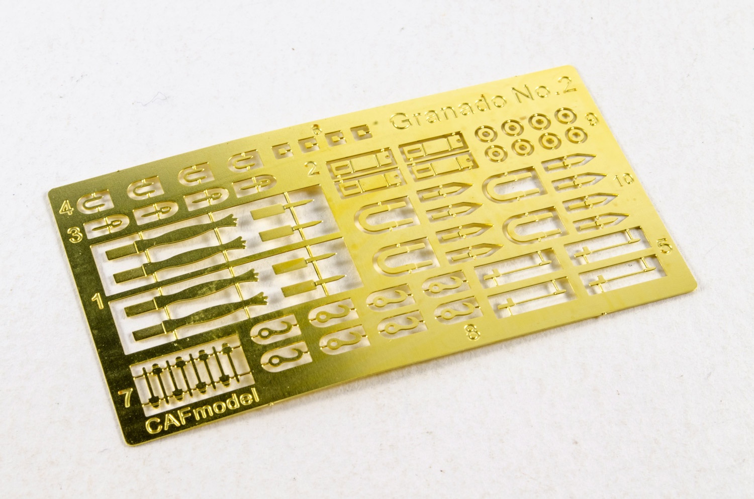
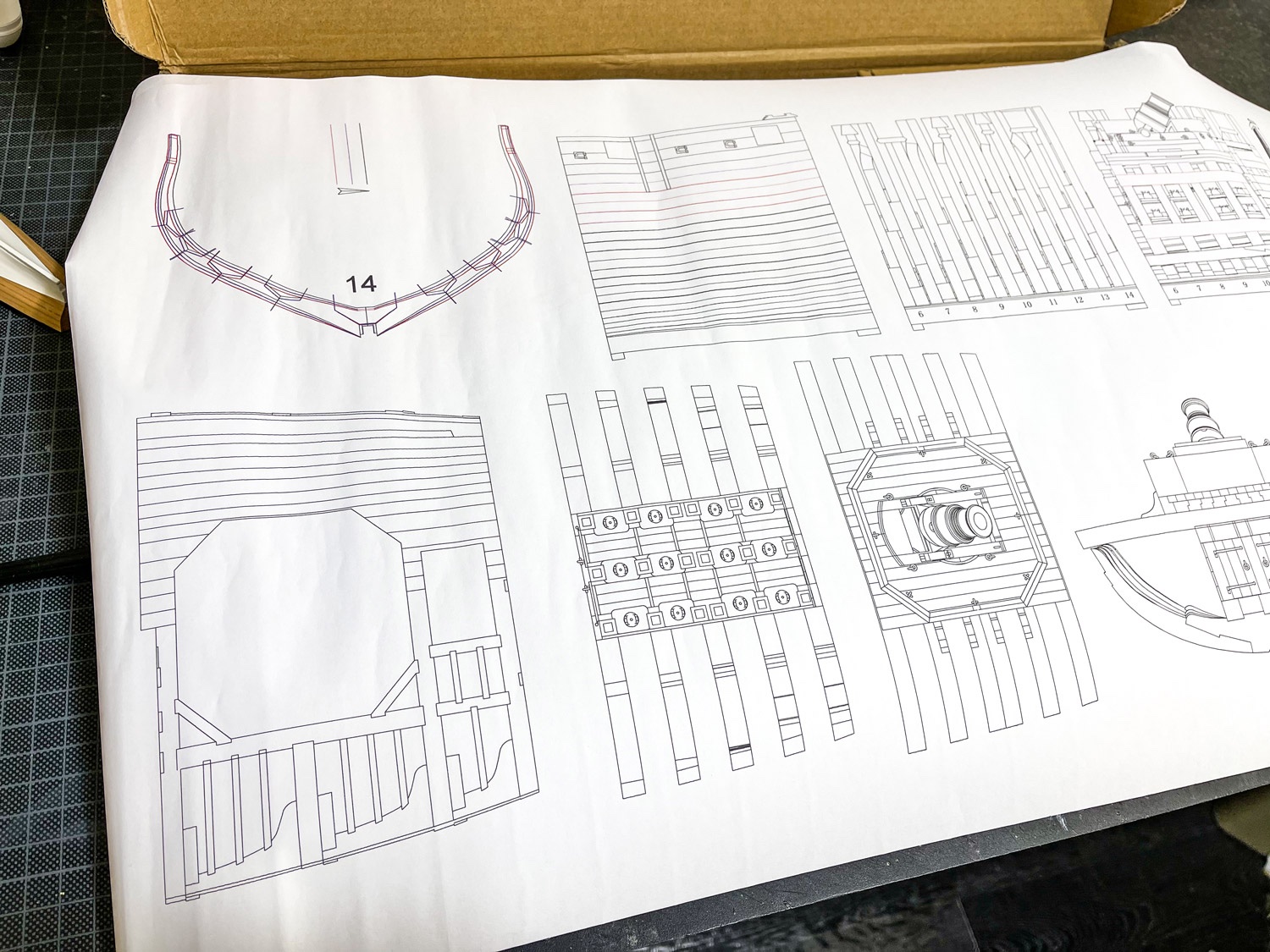
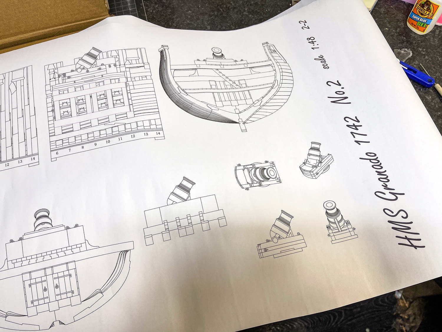
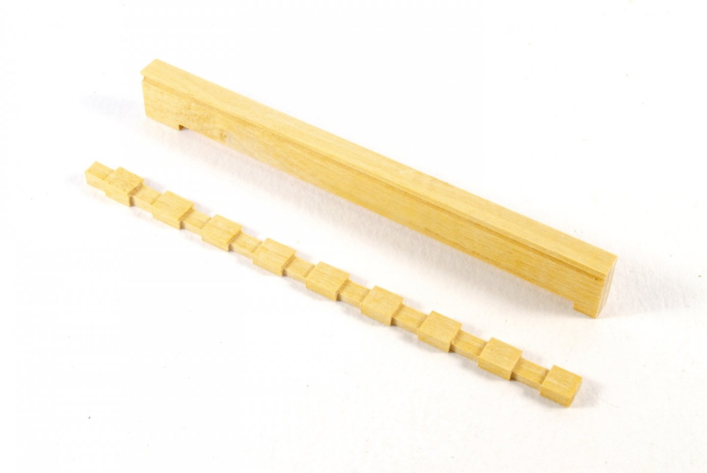
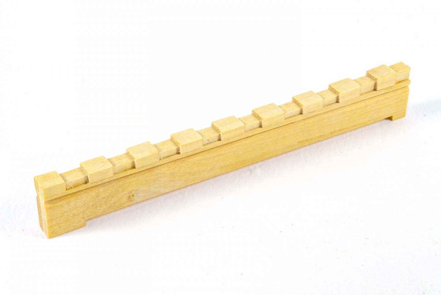
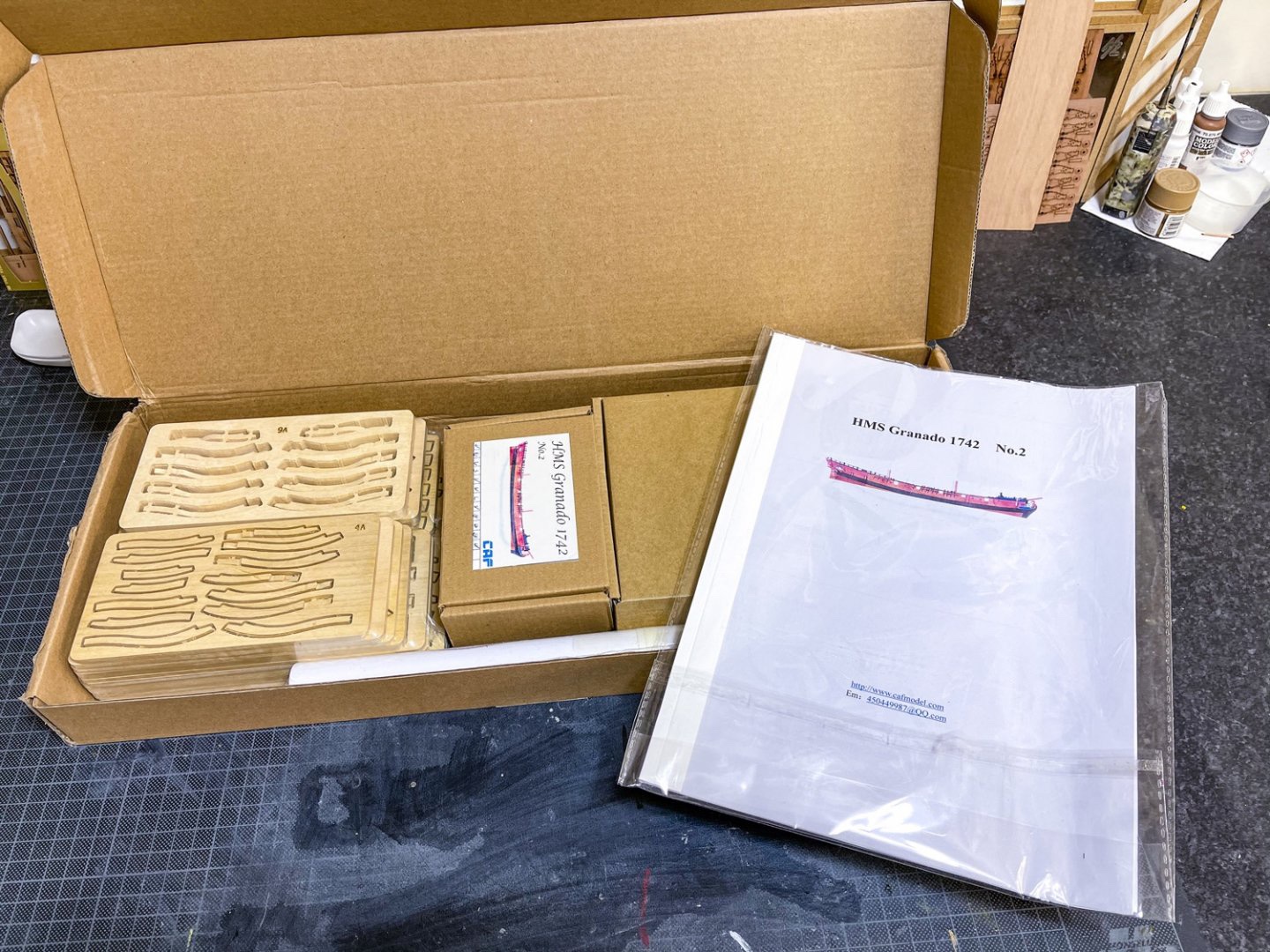
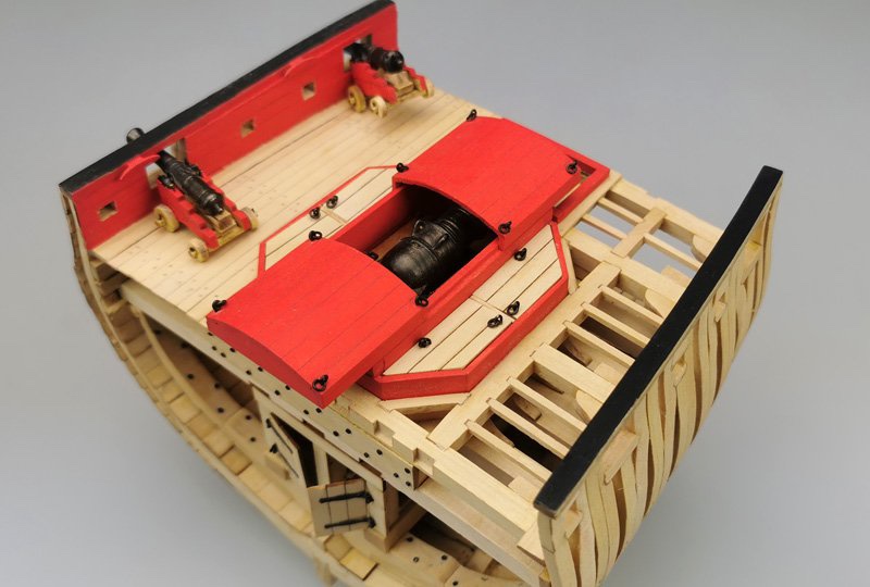
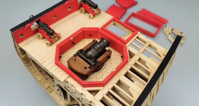
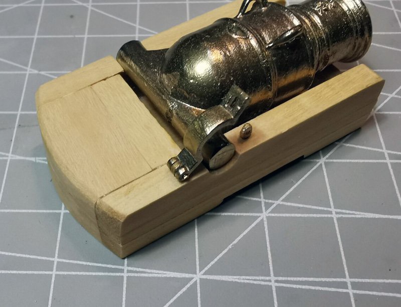
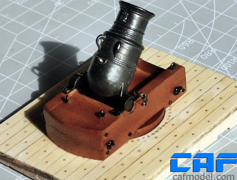
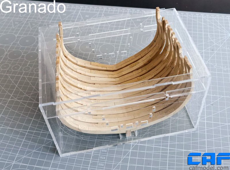
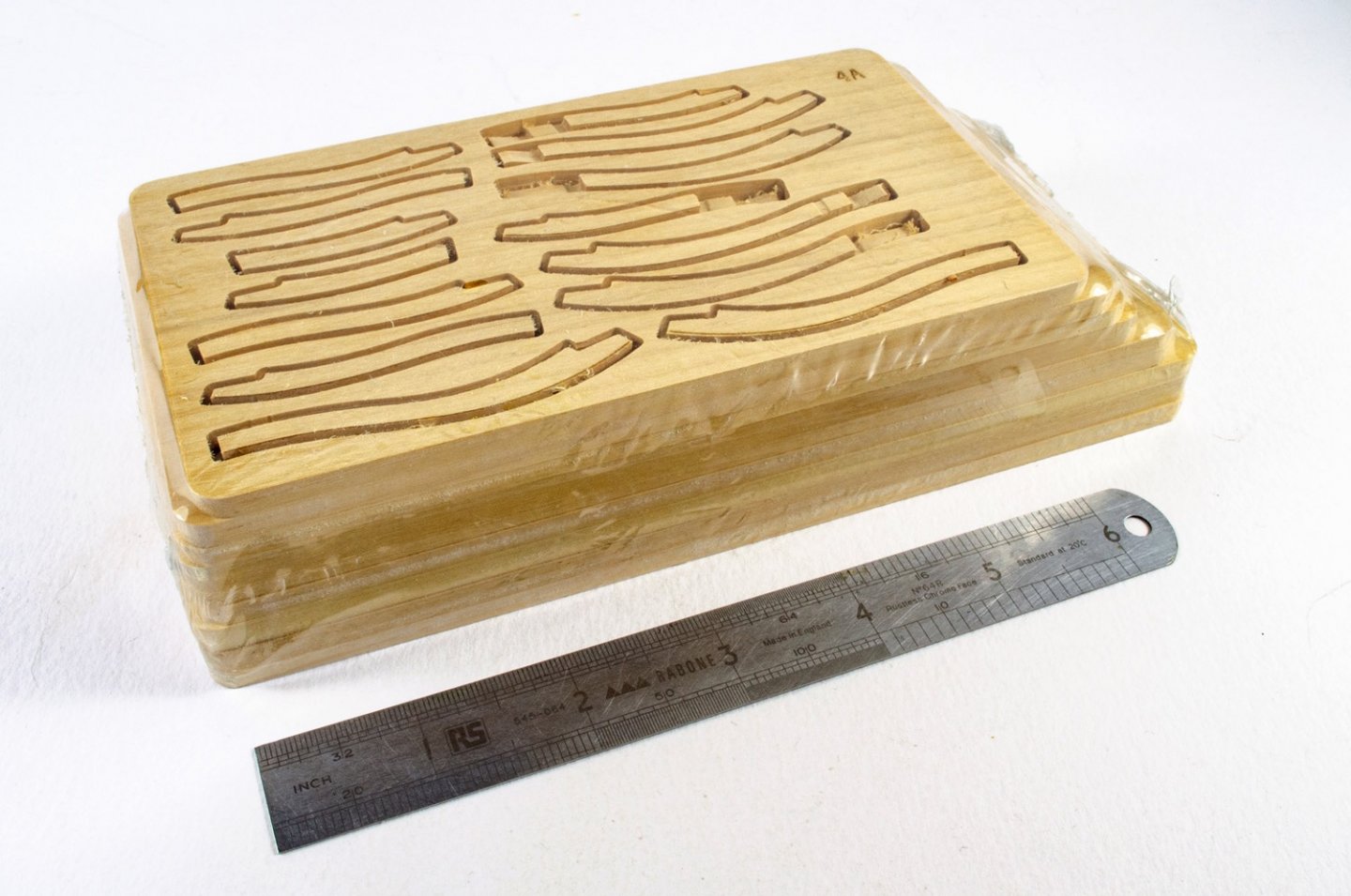
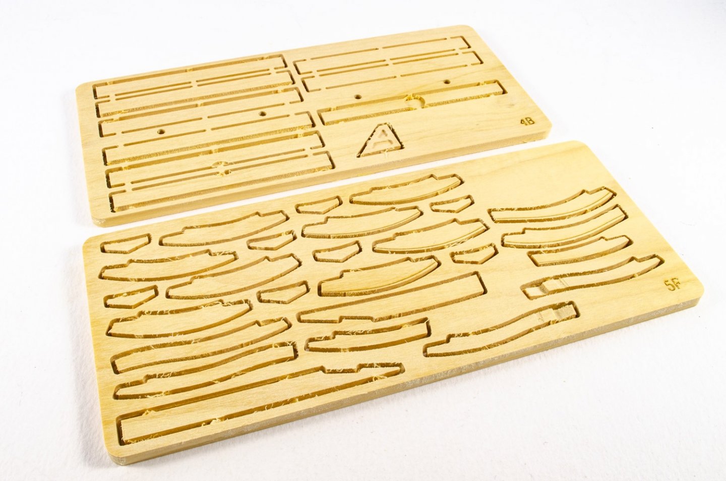
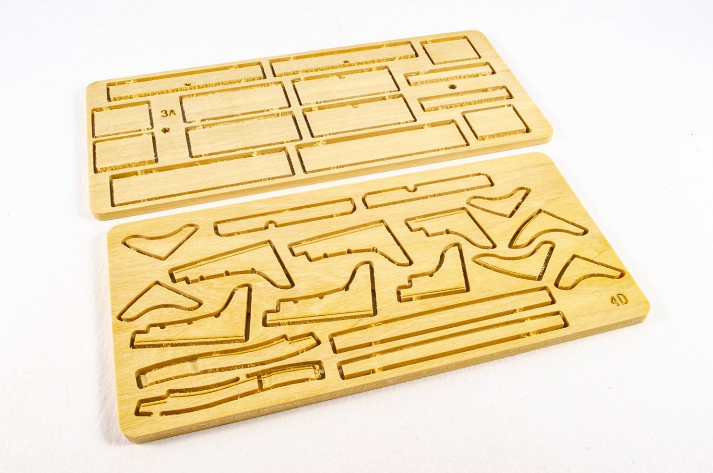
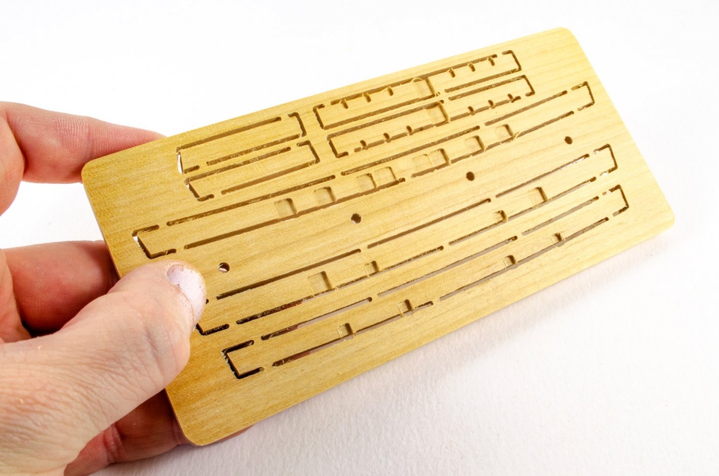
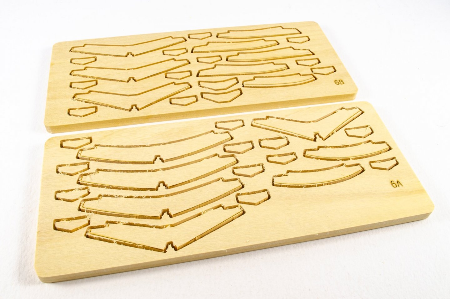
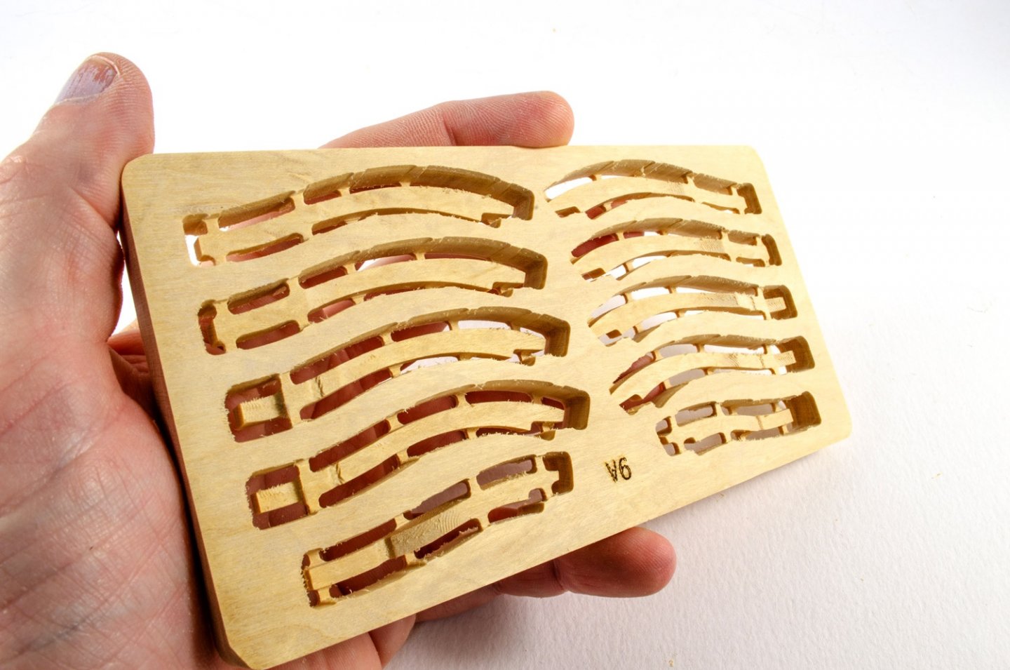
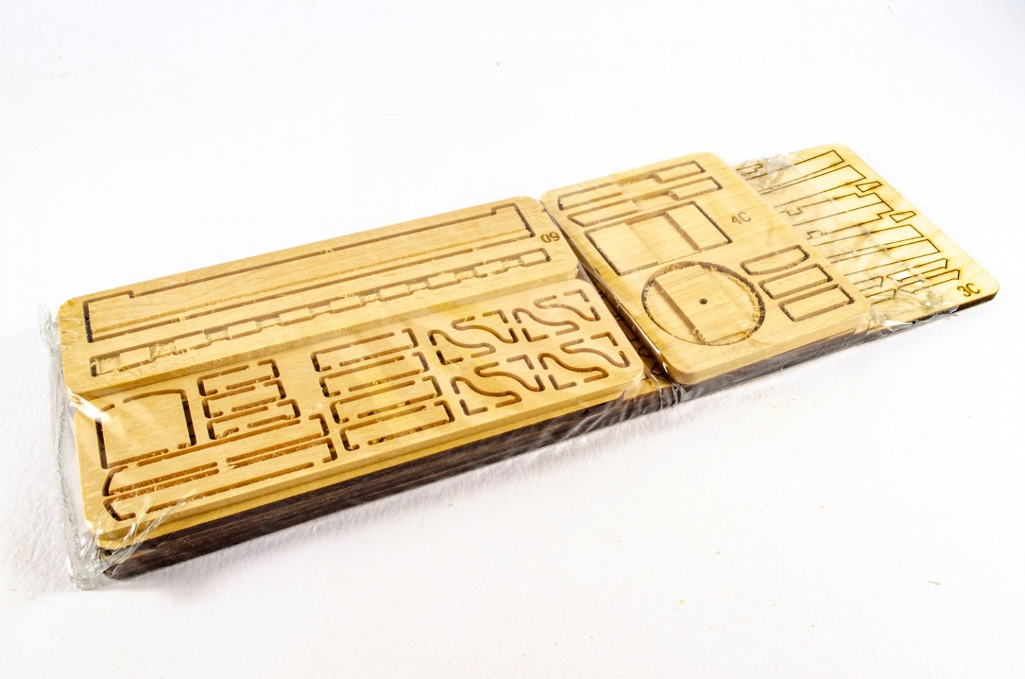
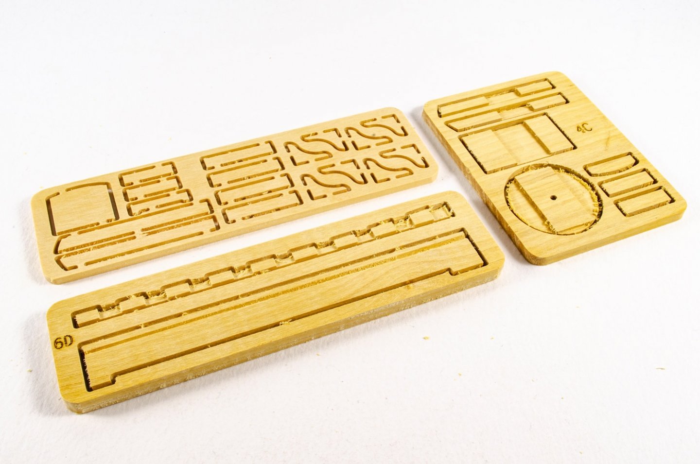
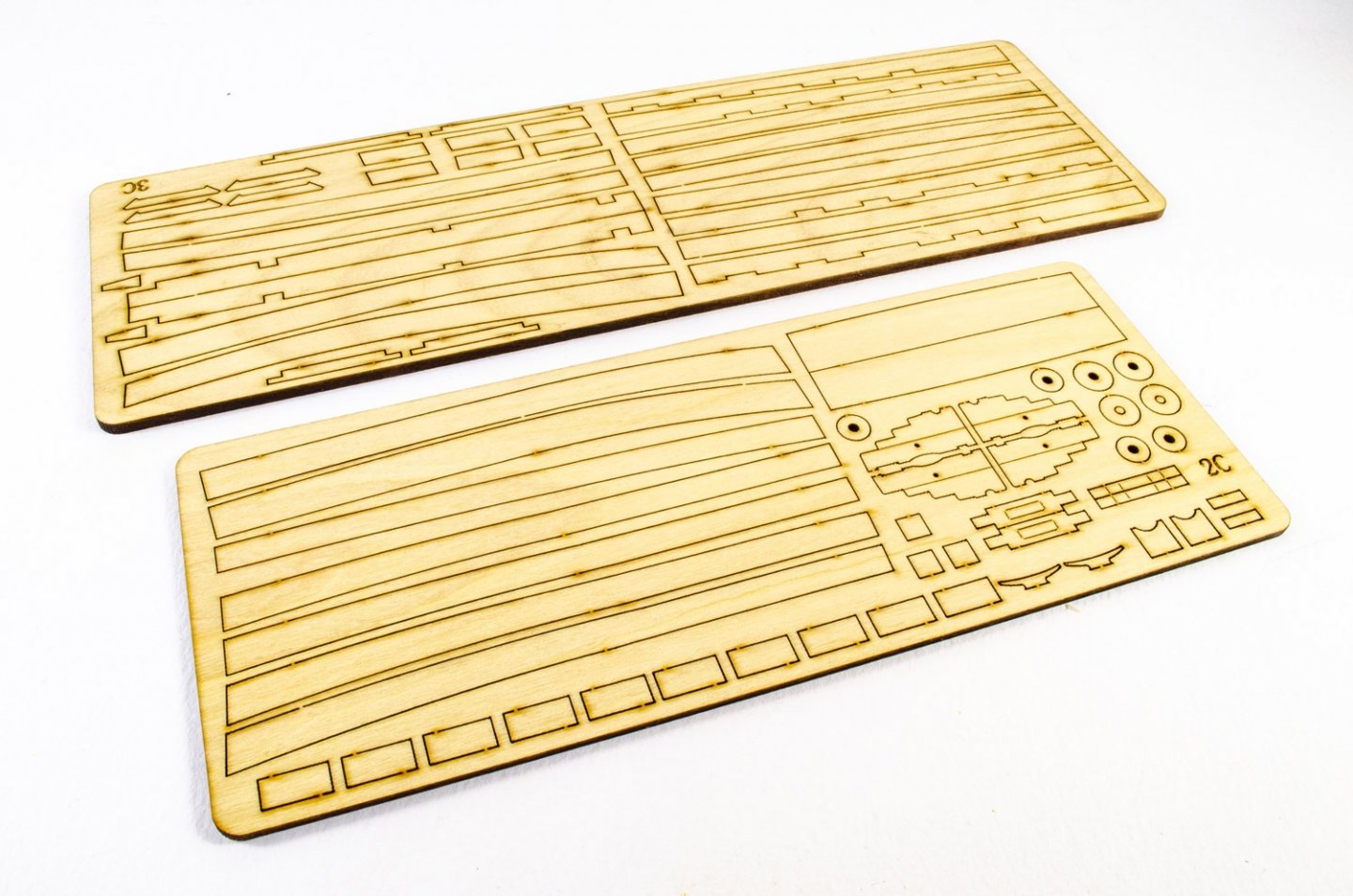
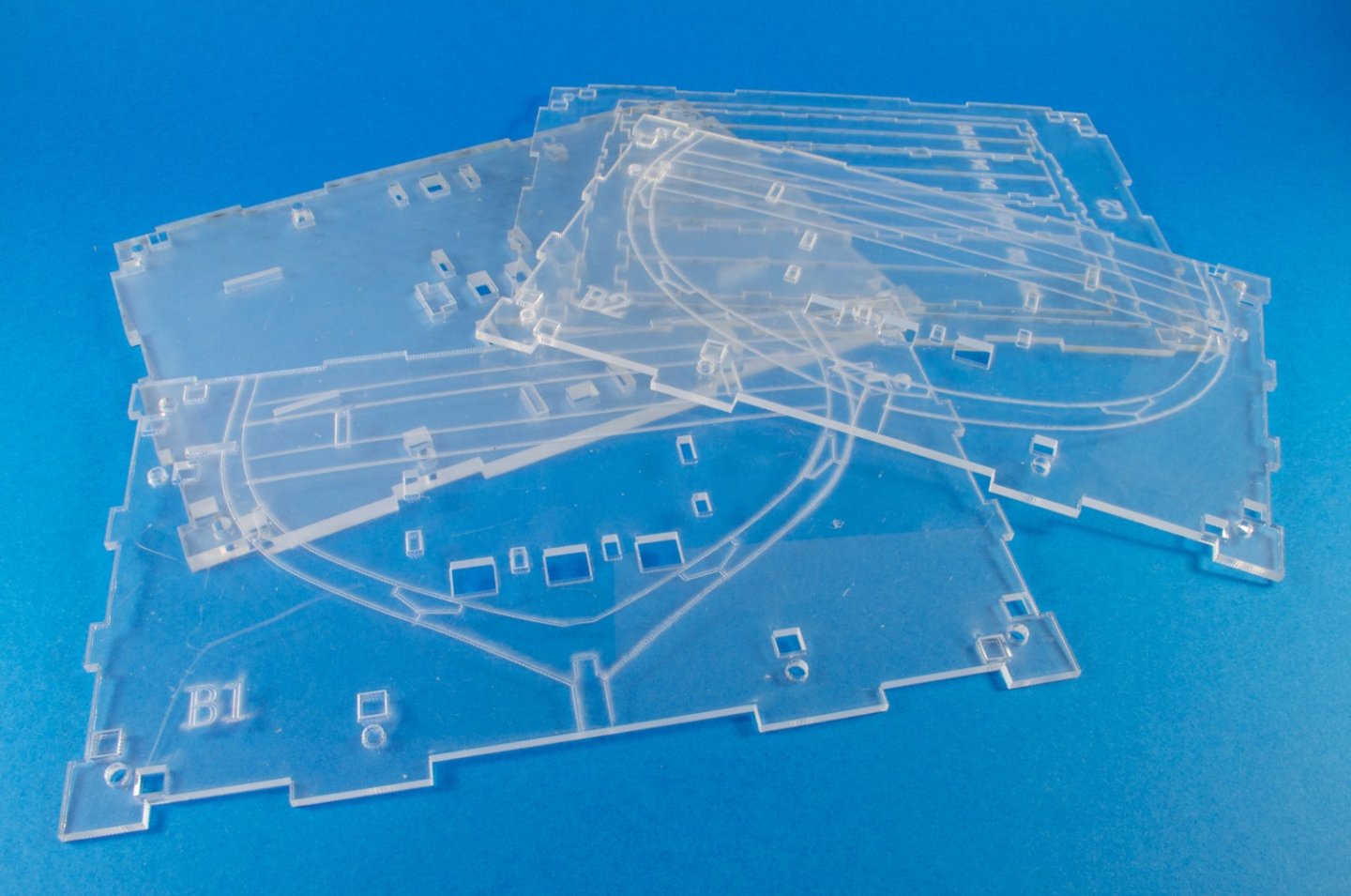
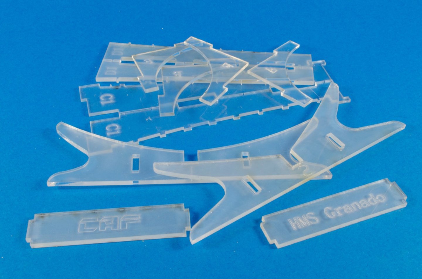
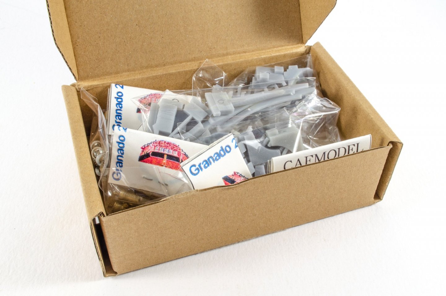
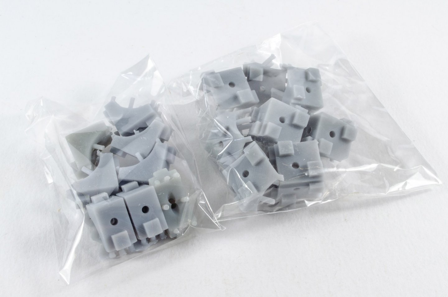
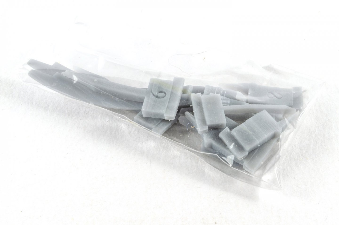
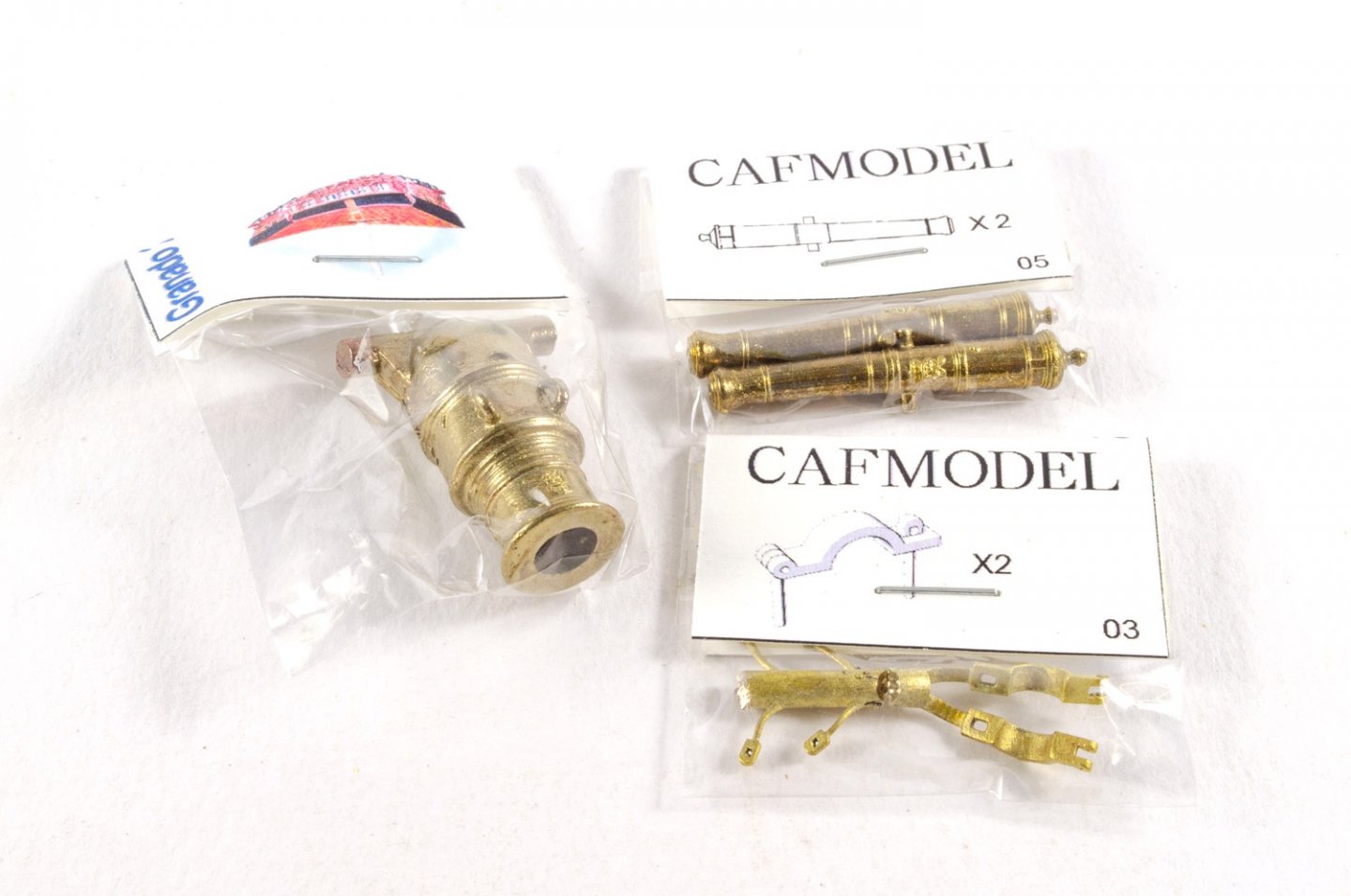
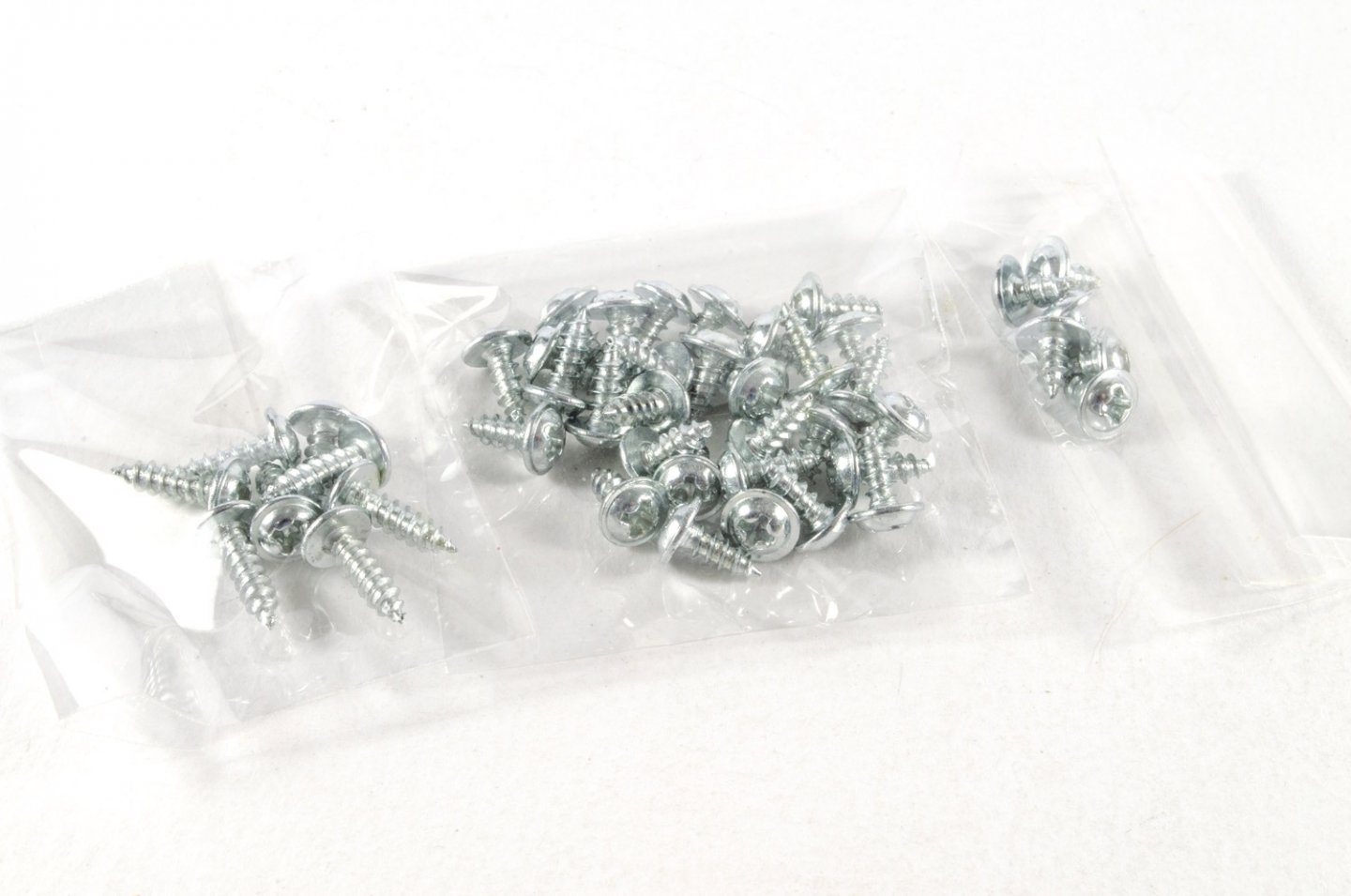
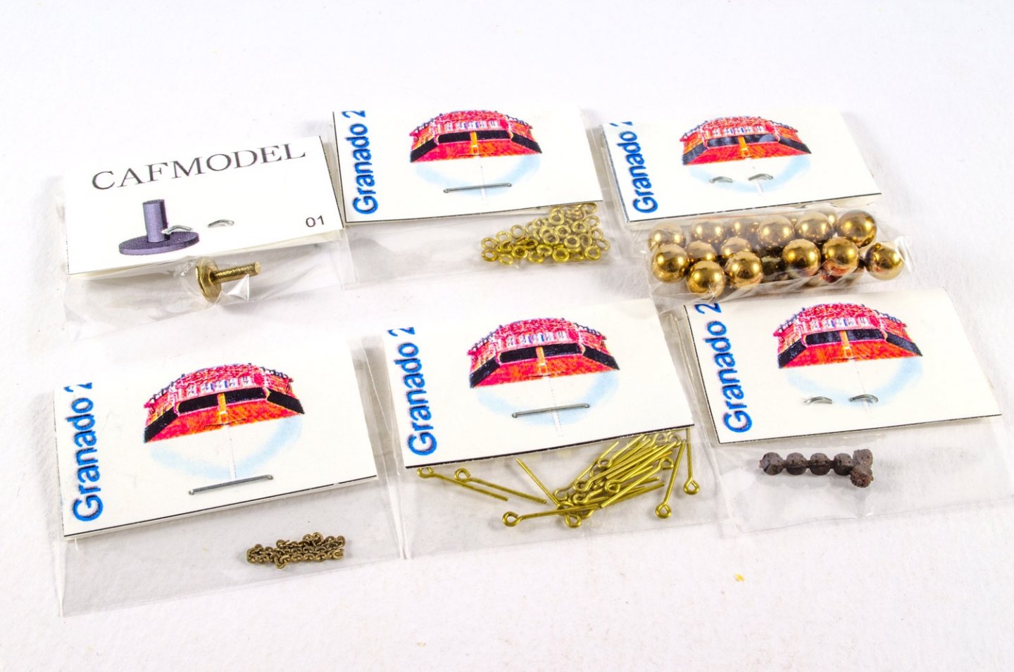
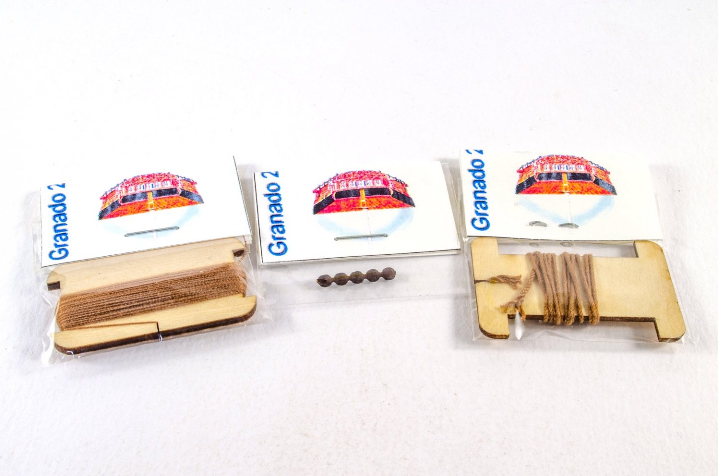
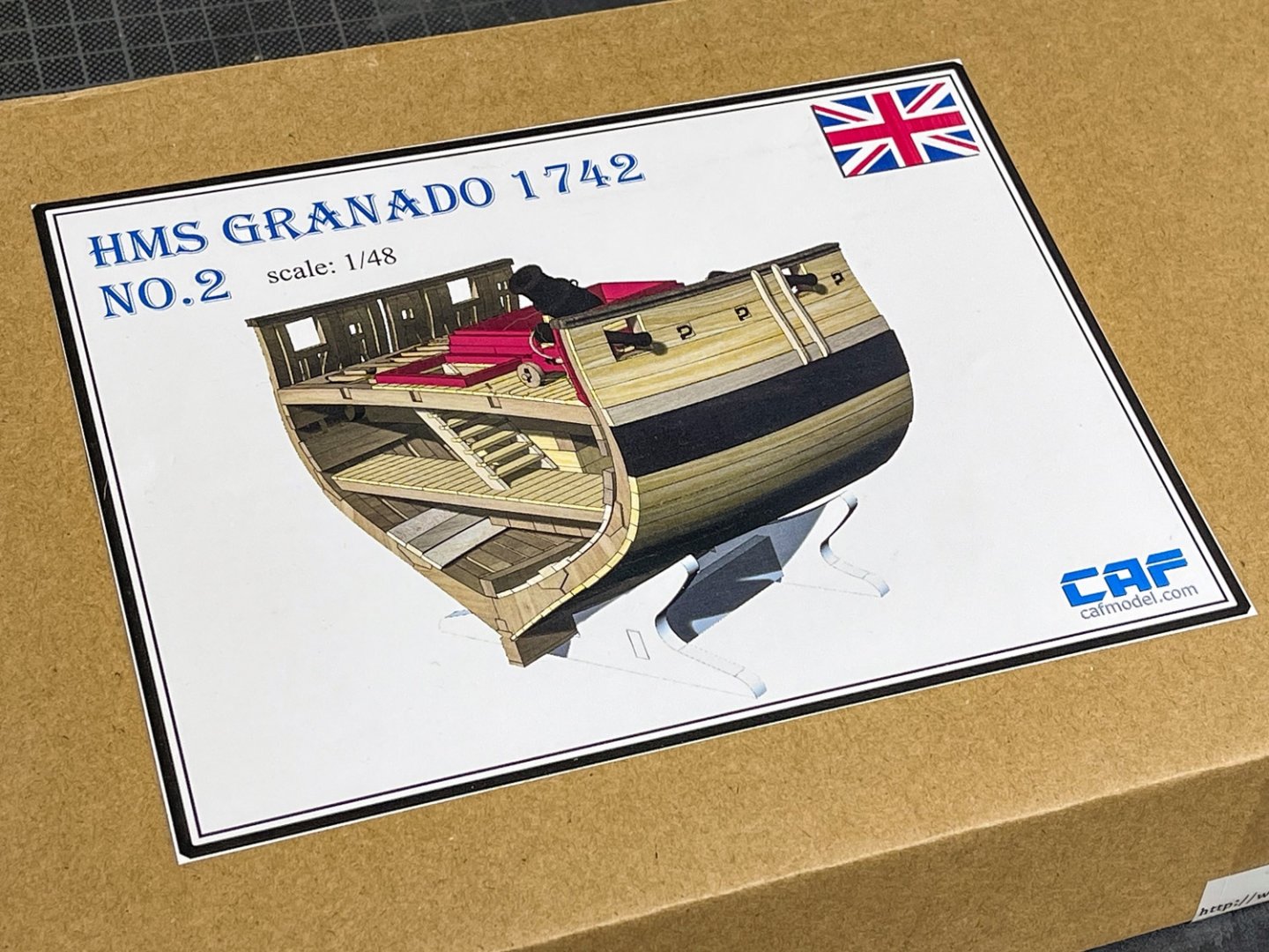
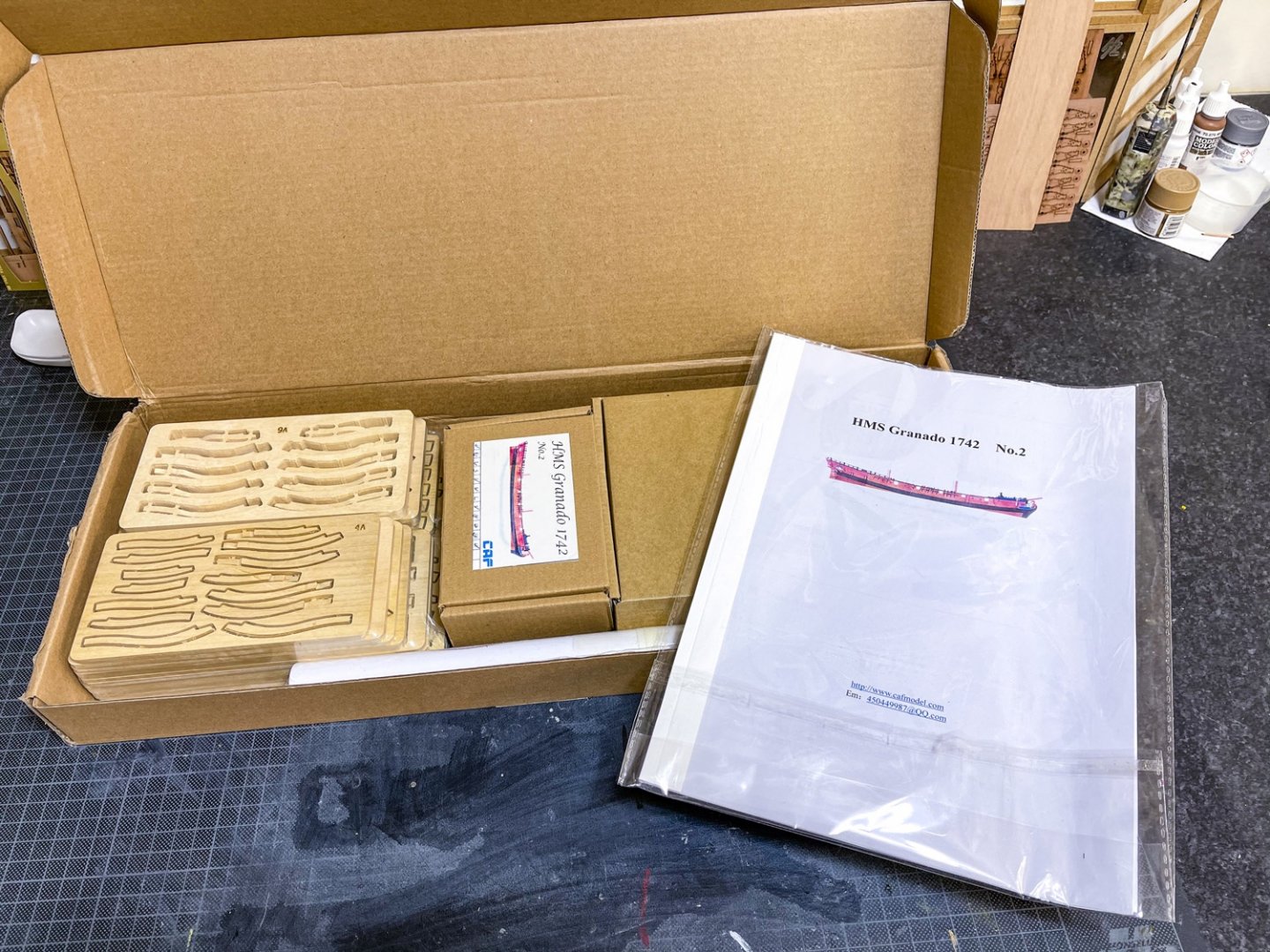
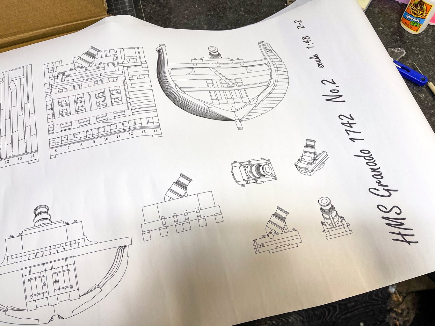
1:48 HMS Granado ‘Cross Section’ CAF Model Available from CAF Model for $325.00 The Granado, a bomb-vessel that was originally fitted out as a sloop (and ended her life as a sloop, also) was thought to have been designed by Thomas Slade. She is definitely a subject which has proven quite popular over the last 20yrs, with POB kits of this released by Amati etc. CAF Model’s intention to create a POF of this model was met with much interest, but before an eventual release of a full hull model, they have released a cross section kit in the same 1:48 scale. For only a section of a complete vessel, the box for this release is quite heavy and still of a reasonable size. Packed into a slimline corrugated box with a Granado label affixed to the lid, the kit reached me in the UK wrapped in a thick layer of extra card to protect it and reached me unscathed. Tom at CAF Model sent this kit minus two small sheets of parts which are now en-route to me, as he wanted MSW to be able to feature this as soon as possible. When those parts arrive, I’ll update this article with those extra photos. I quite like innovative features in model kits, and we’ve certainly got that here with the unique (at least I’m pretty sure!) building jig that accompanies Granado. Remember, that like all my reviews, this is an ‘in-box’ review and is designed to show you the contents of a kit as it comes, with any observations etc. How a model builds will be dependent on various other factors, but I will be featuring this as a build log on MSW in the coming days. CAF kits now have a break seal on them that needs to be cut through before opening, and when the lid is up, this quite heavy box can be seen to be totally chock-full of parts and other components. This kit has four heat-shrunk packs of timber in both laser and CNC cut types, a pack of strip wood, a box of detail components, a box containing the build jig, two sheets of rolled plans, and an instruction manual in a sleeve, also containing a small fret of photo-etch parts. I’m not too sure what timber this model is made from, but it has a nice pale-yellow hue and a very fine grain that’s certainly akin to some of the fruit timbers I’ve used over the years. As stated, all the parts sheets are sealed in shrink wrap. This is quite thick and needs a sharp knife to break through. Many of the parts sheets are just a few inches long, ranging from some quite thick sheets, to one which is just a veneer. Most are CNC cut and also pre-shaped on a multi-axis machine. Two similar packs to this are included in the parts total, and all contain exclusively CNC-cut/routed parts. The steel rule in the photo will give a good idea of the size of these sheets. Here you can clearly see the CNC routing and the extra shaping on some parts. Also note the laser engraving too, for the bevelling lines. These lines are also engraved on the rear of some of these sheets. All sheets are clearly numbered with laser-engraved marks too, but the actual parts numbers will be checked against a part plan in the manual. This helps to save precious production time as engraving the sheet would doubtless add extra expense to the modeller. The fames for the model (18 in total), are constructed in the same manner as their real counterparts, and also include the ‘bends’ in them that were typically seen in vessels of this period. This is where the CNC routing comes into effect, producing those complex shapes for the modeller, saving not just time but also the complications that result from recreating such parts by hand. To be able to position these frames against each other accurately, a series of temporary resin inserts are also included. We’ll see those shortly. Here you can see the breakdown of the frames into the various components including futtocks and chocks. A nice enhancement would be to use something that would represent fastenings in the complete frames…maybe black fishing line/filament which would look like nail heads. Deck beams are pre-cut to shape, including rebates for deck support timbers etc. More frame timbers with their engraved position/bevelling parts. Here you can also see the frame sections (top) which form the bottom of the frames that sit upon the keel. These photos give an excellent idea of the CNC shaping of the most complicated timbers, allowing this to be a nice introduction into POF modelling, whilst removing what would be the most frustrating elements. Two longer packs include more CNC-machined/routed parts, but also a series of laser-cut sheets. Clearly seen in this photo are keel parts, knees and parts for the gun mount. And now some laser-cut wood! One thing you won’t need to worry about is shaping any planks, especially internally, where that is a little more complicated. Granado is planked internally and externally, on one side only, giving the viewer the ability to see a complete hull on one side, and skeletal on the other. You will also see cannon carriage parts here too. This is the last pack of timber parts, again comprising both CNC and laser cut elements. More planking here, and also parts comprising the gun deck and hatch covers. Sheet 1A is a veneer. These appear to be facing parts for at least two frames. This is a highly prefabricated kit, making it perfect for that intro to POF, as can be seen from more pre-shaped planking etc. Whilst a gentle sanding of all laser parts is a good idea to remove any surface heat marks, you would need to see how the edges look when together as far as the char goes. Instead of using this for ‘caulk’, it could be a good idea to remove this char and simply use a pencil to represent caulk, as it’s less stark. The largest box inside this kit contains that unique feature I mentioned earlier. That is a clear acrylic building jig. Not only does this take over from the traditional ply jig we are used to seeing, but it’s also engraved so you can check alignment from every conceivable angle. This is assembled using short screws which also fasten into a series of specially cast resin blocks which keep everything square. The jig itself is a work of art. It’s a shame it’s disposable. However, more acrylic parts are included for a final display stand, engraved with the ship’s name. All acrylic parts are protected with a layer of peelable film. The second and last box contains all the various fittings etc. These are the resin blocks which are used to construct the clear assembly jig. I mentioned earlier about resin inserts which temporarily sit between twisted frames, to help with their positioning in relation to each other. These are those. When the frames are set, these are disposed of. Screws for assembling the acrylic building jig. These parts are very obvious. Here you see not only the main mortar with its beautiful detail including royal crest, but also the two cannon for the framed side of the hull. The other pack contains the capsquares for the mortar, and these are actually workable! Casting really is very nice and there’s minimal clean up. As these are brass, that aspect will be very simple with a nice set of files. More packs contain eyebolts, bombs, deadeyes, eyelets, swivel gun mount, rigging cord etc. There isn’t too much strip timber in this kit, but there really doesn’t need to be. A small length of brass wire is also included. A single fret of PE is included. Production is excellent, with small connecting tabs. You’ll find cannon and hull fittings here etc. Plans and instructions Two sheets of plans are included. One of those covers all the frame assemblies, whilst the other also has various illustrations of the completed hull to help with overall assembly. These are quite long sheets and need double rolling to remove the curl in the sheets as they are quite tightly rolled. The instructions are line drawing format but also contain colour. These look pretty easy to follow and the writing is clearly understandable. Conclusion As well as being an interesting subject of a popular vessel, this is going to be a perfect introduction to the world of POF. Being 1:48, this is also a nice size too without being too large for your shelf. I know some modellers would like to build in 1:48 but could find it restrictive when it comes to displays. This should alleviate that problem! Overall, this looks a very nicely designed and produced kit with some very nice and innovative features. Most importantly too, it looks to be real fun to build! Head over to CAF and snag yourself one. My sincere thanks to CAF Model for the review sample seen here.


-
1:8 1965 Shelby Cobra 427 S/C - Agora Models
James H replied to James H's topic in Non-ship/categorised builds
STAGE 31: BRAKE PARTS FOR THE REAR RIGHT WHEEL Lastly, another brake unit is built. This time for the rear right wheel. That's it until next time! -
1:8 1965 Shelby Cobra 427 S/C - Agora Models
James H replied to James H's topic in Non-ship/categorised builds
STAGE 30: LEFT LOWER SUSPENSION ARM AND SHOCK ABSORBER Using another serrated pin, the cylinder body is now fitted into position. Now, the cylinder piston is connected to the lower arm. With the coil spring in place, this unit is then offered up to the assembly and pinned into position. At this point, there's a lot of tension in this! -
1:8 1965 Shelby Cobra 427 S/C - Agora Models
James H replied to James H's topic in Non-ship/categorised builds
STAGE 29: REAR UPPER SUSPENSION ARMS More serrated pins are used to connect the rear upper arms to the arm holder. The differential unit is now loosely sat in place and connected to the engine by the propeller shaft. With this is situ, the arm holder is screwed into position, trapping the differential unit, and the arm is connected to the brake unit with another serrated pin. -
1:8 1965 Shelby Cobra 427 S/C - Agora Models
James H replied to James H's topic in Non-ship/categorised builds
STAGE 28: DIFFERENTIAL HOUSING COMPONENTS AND PROPELLER SHAFT The rear differential housing cover pushes into housing unit, and then the top of the housing unit is screwed into position. The propeller shaft is carried over onto the next stage. -
1:8 1965 Shelby Cobra 427 S/C - Agora Models
James H replied to James H's topic in Non-ship/categorised builds
STAGE 26: BRAKE PARTS FOR THE REAR LEFT WHEEL As with the right brake unit, the left one is now built. Oddly enough, the wheel hub is shown as silver in the manual, but this is a nice black coated metal part. STAGE 27: DIFFERENTIAL HOUSING COMPONENTS The inboard drive shaft connectors are screwed to the bottom of the differential housing. Both drive shafts are now fitted and held in position with a serrated tipped pin. The drive shafts are labelled L and R to make sure they go on the correct sides. This is important due to the various offsets in each part. The left rear wheel brake unit is now pinned into position pin the same way.