Mark P
-
Posts
1,765 -
Joined
-
Last visited
Content Type
Profiles
Forums
Gallery
Events
Everything posted by Mark P
-
 Hi Redshirt; Thanks for your post. If they used double frames then your suspicions are correct: they would not be what I am looking for, unfortunately . I also forgot to specify that I am looking for examples of English vessels. All the best, Mark P
 -
Hi everyone; As there don't seem to be many examples of warships built with single frames, does anyone have any information on the construction of 18th century merchant vessels. I am interested in single-frame construction, without the double frames used in warships. Unfortunately, while I have a good reference library of Naval vessels, I have nothing on merchant ships of this period. However, I am pretty sure that as the single frame method was used at a later date, it would have been used earlier. I would be grateful if any fellow modellers could point me in the right direction for a clear illustration, or a book to enlighten me. Many thanks for any help. All the best, Mark P
-
Single frame construction
Mark P replied to Mark P's topic in Building, Framing, Planking and plating a ships hull and deck
Thanks Druxey; I will look into her. If anyone knows of any others, please let me know. All the best, Mark P -
Does Anyone Know? I am interested in any examples which fellow modellers may have come across, where a Royal Navy warship of the 18th century was constructed entirely of single frames ie with no paired frames (bends) All frames would have been like filling frames in normal warship construction, with alternating floors and first futtocks. I would like to know how common was this form of construction. Any help would be much appreciated. All the best, Mark P
-
Plank bending for real
Mark P replied to Srodbro's topic in Building, Framing, Planking and plating a ships hull and deck
Hi Dafi; Interesting pictures; thank you for posting them. The name on the boat chandler's shop next door seems slightly optimistic! All the best, Mark P -
Questions about double wale
Mark P replied to Erik W's topic in Building, Framing, Planking and plating a ships hull and deck
Hi Herring; Not sure, and no reason is given. But in general changes were made for only two reasons: to enhance the ship's capabilities, or to save money/timber. As the change actually used more timber, it would seem that it was to improve the vessel's performance, and was an increase in her structural strength; especially as the timbers could then be laid in hook and butt, which helped to prevent movement. All the best, Mark P -
Greetings gentlemen; I agree with Allan above: this thread has thrown up a lot of potential items to track down and read. One more source of interest is Franklin's 'Navy Board Models, 1650 - 1750' in which he discusses the methods of framing used for models, and concludes that some of them, despite seeming rather odd by later standards, actually represent contemporary methods of construction. All the best, Mark P
-
Questions about double wale
Mark P replied to Erik W's topic in Building, Framing, Planking and plating a ships hull and deck
Hi Erik; Your mention of painted friezes raises an interesting point. I cannot claim to be an expert on the subject, but from personal observation I think that these were more common than a modern observer, thinking firstly of the expense involved, might expect. One thing to keep in mind is that the sailing man-o'-war was the ultimate visible expression of a country's international prestige, and was visible to a large number of people during her career. Additionally, it was only in the very first years of the 18th century that the custom of covering ships in swathes of elaborate carving had ceased, and painted frieze-work would seem to be a cost effective substitute for this. To pass from these more theoretical points, to the availability of real evidence, I can offer several examples of actual frieze painting in real vessels. The picture by John Cleveley the elder, showing the 'Royal George at Deptford for the launch of the Cambridge' shows the George with painted friezes. The as-built draughts of 'Fly' and 'Bristol' show detailed depictions of frieze-work (there is a model of the 'Bristol' in the Art Gallery of Ontario, which shows her with frieze-work which is slightly different. This model is known to have been made by George Stockwell, who left his name on a piece of paper inside, and the date May 7th 1774. He describes himself as a shipwright at Sheerness dockyard, which is where Bristol was built. She was ordered in 1768, and her keel was laid in 1771. As the model was completed? in May 1774, but she was not launched until 25th October 1775, it would seem reasonable to suppose that the model's frieze-work was not based on reality, as she had probably not then been painted, 18 months prior to launching. George Stockwell presumably created a typical design drawn from experience, whereas the draught shows her as completed much later) I have seen other draughts which give details of the painted decoration on the lower counter and quarter-galleries. Additionally, I have seen references to decorator's bills for painted frieze-work on ships. As neither 'Fly' nor 'Bristol' were vessels of any particular note at the time of their launching, it would seem reasonable to assume that what happened to them was typical of the times. Painted friezes probably finally vanished under the vastly increased workloads the dockyards had to carry out during the Napoleonic wars. All the best, Mark P -
Questions about double wale
Mark P replied to Erik W's topic in Building, Framing, Planking and plating a ships hull and deck
Hi Erik; Herring above is essentially correct, but strictly speaking double wales were made obsolete by the 1719 establishment, which says of wales: 'Wales: and the Stuff between them to be of an Equal Thickness: To be worked withe Hook and Butt' It then lists the various widths and thicknesses of wales for the different rates. For example, 60 gun ship 3'10" wide x 7" thick. However, some vessels continued to be built with double wales, primarily first rates, I think (I stand to be corrected on this point) The Royal Yacht 'Royal Caroline' launched in 1749 had double wales also; possibly because her predecessor had them, and the new yacht was pretty much a copy as far as hull design was concerned. The model shown above is not firmly identified, but features in Brian Lavery's book 'The ship of the line: a history in ship models', where he describes several of the model's features as being rather old-fashioned, including the double wales, full-length lateen yard, and location of the channels. The model is believed to be the 'Yarmouth' built to the 1741 establishment. The 'dockyard' style of open hull framing was also going out of fashion around this time, being replaced by the 'Georgian', which features solid, normally planked, hulls. It is therefore just possible that the model does not represent the vessel as actually built, but as a traditionally-minded model builder wanted her to appear. All the best, Mark P -
Greetings everyone; Before the mid 18th century, only two tackles were issued per gun. After this, three per gun were issued, but never more, so it is unlikely that two tackles were hooked to one side of the gun. The tackles at the side of the gun would have been hooked to whichever ringbolt in the ship's side best served the need at that moment: to traverse or to run out. Doubtless hand-spikes or crowbars were still needed to assist the traversing. The increased traversing ability led to changes in the way that the breeching rope was attached to the cascabel at the breech. For many years, it was cu(o)nt spliced, or looped and seized, around the button, but if the gun was fired at any angle other than 90 degrees to the centre line, one side of the breeching rope would pull taut before the other. The final solution, after experiments with passing the rope through thimbles stropped to the button, was to cast an integral ring at the cascabel, which allowed the breeching rope to be adjusted from side to side. This appeared in the Blomfeld pattern guns, a greatly improved design, which were put into production just in time for the wars with revolutionary France and then Napoleon. All the best, Mark P
- 16 replies
-
- 7
-

-
- Gun tackle
- Triton cross-section
- (and 2 more)
-
Hi everyone; The location of the eye-bolt in the ship's side, further from the gun-port, was relatively new at this period, and was done with the sole aim of making it possible to traverse the gun through a wider arc of fire. Previously the eye-bolts had been much closer to the sides of the gun-ports, as shown by the other line in the first illustration posted. This was all part of a package of improvements to naval gunnery pioneered by Sir Charles Douglas between 1778-1781; who, amongst other things, also perfected the flintlock firing mechanism by using priming tubes of goose quill, rather than thin metal (which could fly out as razor sharp fragments on firing) and introduced flannel cartridges (which left no burning residues in the barrel after firing, and so were much safer, and enabled a faster re-load) For more on this, see the chapter on HMS Duke in the Seawatch Books publication about first & second rates in the Rogers Collection. All the best, Mark P
- 16 replies
-
- 5
-
-
- Gun tackle
- Triton cross-section
- (and 2 more)
-
Hi Frankie; You are quite right, that we are here to guide and learn where needed. I hope that if I am wrong I will be corrected, as I would much prefer to be correct, just as you say. No offence intended; and you are, after all, right about the burton pendants not being part of the shroud. My only thought was that if some members only read the last few posts, they may not realise exactly what Darrell was unsure about. Your post of that part of the instructions does make that clearer. All the best, Mark P
-
Hi Frankie; Don't be too hard on Darrell; he does say he is not sure if this is the right way to do it, it's what his plans show. As Druxey says above, the burton pendants were cu(o)nt-spliced over the masthead. So in correct usage, your scepticism is well-based, and there was no connection between the shrouds and the pendants. All the best, Mark P
-
Hi Mike; It is a large book, about 2" thick and 12" tall. It has a wealth of illustrations and scale drawings of cannon barrels and carriages, as well as a detailed text. It is written by a man who had a lifelong enthusiasm for cannon, and who had extensive knowledge of the Ordnance Board's records. I have not seen the earlier volume, but the 18th century one describes the development of sea artillery, and deals with every aspect of design, manufacture, use and maintenance. It is broken up into chapters dealing with each separate period of peace and each of war during that century, and covers the period from 1715 to 1815. Some of the information is in tabular form, but the book is far from a collection of lists, and is interesting to read. If you are keen on producing accurate scale armaments, or trying to obtain an in-depth knowledge of the subject, it is perhaps worth the cost. I found one on Amazon.Japan for $250, and snapped it up, although the postage was horrendous, as the seller did not normally ship to England (I managed to calm down the Admiral over the cost of the book, but she didn't see the cost of the postage, fortunately) All the best, Mark P
-
Hi Mark; The burton pendants were the very first item of rigging to be put over the masthead, but they have no connection with the mainstay, or other stays. You are correct in that they have an eye-splice in the end, around a thimble (after 1780) but this was used to hook up a tackle to raise and lower heavy weights when needed. Burton pendants were fitted to the topmast heads. Their counterparts at the head of the lower masts were called pendants of tackles. Before 1780, the upper block of a tackle was seized into the end, with the tackle made fast in the top below, or to the shrouds, when not in use. The mainstay has an eye-splice in the end, which is passed around the mast-head; the other end of the main-stay is passed through this, and made fast to the top of the stem. The loop around the masthead is prevented from pulling tight around the mast by a specially-shaped object, called a mouse, made by many turns of small diameter rope being taken around the main-stay. It looks pear-shaped when completed, with the thin end tapering upwards along the stay, and the thicker, rounded, end pointing down towards the bows. The finished mouse is then served as part of the serving of the mainstay. The eye-splice then sits snugly against the thick end of the mouse, and can slide no further up the stay. Before being served, the stay was wormed and parcelled; although as only the serving was seen in the finished stay, for models these processes are normally omitted. Hope this helps to clear things up a bit. All the best, Mark P
-
Hello gentlemen; Thanks Spyglass; that is an interesting book. Mike: the length of the breeching rope is the overall length, and would be the length issued from the stores to the ship's gunner. It would therefore be slightly shortened by any splices in the ends. When the gun was fired, it ran back rapidly, until it hit the limits of the breeching rope, which would pull it up with a jerk. This was confirmed by Adrian Caruana during experiments. Without the breeching rope, cannons, when fired, would recoil many yards: I seem to remember about 40 feet for a 32 pounder. Once the gun was run out, ready for firing, the breeching rope was laid out to each side, in order to keep it as far as possible from the path the trucks would follow during the recoil. The gun-tackles were indeed left attached (it was not unusual to mouse the hook that held the tackles to the carriage, which would have made it impossible to remove easily) and care was taken to lay out the fall of the rope in such a way that it would feed easily through the blocks during recoil. All the best, Mark P
-
Hi Gentlemen; Further to Jaager's remark in the previous post, Adrian Caruana, who was an expert in smooth-bore artillery, and had fired many of them experimentally, wrote an excellent book about 18th century (and another on 17th century) cannons. This is called 'A History of English Sea Ordnance', and for those who can get hold of a copy, it answers most things. He carried out extensive research into the archives of the Ordnance Board, which was actually responsible for Naval cannon, and was nothing to do with the Admiralty or Navy Board (much to the frustration of these bodies) He gives a table dealing with breeching ropes, and discusses the variations in how they were attached to the cannon's breech, and ship's side, over time. His table gives various measurements from official sources (although there are not many of these) His conclusion is that the rule quoted near the beginning of this thread (which is taken from Simmons' 'A Sea-Gunner's Vade-Mecum', published in 1812, although parts of its descriptions only apply to earlier periods) that the breeching rope length is 3 x the bore (length) is correct enough. Although the resulting measurement should be rounded up to the nearest foot. All the best, Mark P
-
Thanks everyone for your replies. I had a feeling that there was some scepticism shown in earlier posts on this subject, about the use of belaying pins before the mid 1700s. Without doubt they became much more widely used around the later 1700s, but it is good to know that the Greeks used them. That does indeed make them pretty ancient. All the best, Mark P
-
Greetings fellow modellers; Following on from several discussions on this forum, concerning how widespread was the use of, and when was the introduction of belaying pins, I believe that the following information will be of interest to many. At least to anyone considering using some pins on a model, perhaps in the ends of the bitts cross-member, where I have occasionally seen them depicted. I have recently been re-reading my copy of the Sea Watch Books volume on the first and second rate models in the Rogers Collection at Annapolis. The second model dealt with here is the 'Saint George' of 1701, a 94 or 96 gun second rate. The model is believed to show her in around 1702, as it has the cipher of both William lll, who died in that year, and Queen Anne, who succeeded him. The most remarkable thing about this model is that it has the oldest (according to the book, anyway) set of complete contemporary rigging known on any dockyard model, making the rigging over 300 years old. Anyway, clearly shown on the rail atop the beakhead bulkhead on this vessel are eight belaying pins, looking just like any of the later belaying pins featured on younger models. The end of at least one can clearly be seen hanging below the rail. I have not seen this on any other model. Would this constitute the earliest example, or does anyone know of an earlier one. All the best, Mark P
-
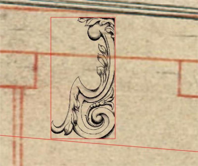
Inserting scanned object
Mark P replied to Mark P's topic in CAD and 3D Modelling/Drafting Plans with Software
Hi Jaager; Thanks for your advice. I understand CAD well (far less well than some who put examples of their work on here though) and know little of graphics programmes (although I really wish I did know far more, but I have no time to learn) So I need to use a method that allows me to insert objects into CAD drawings. With FatFingers' much appreciated help, I have found a way to do this. Thank you to all contributors for their thoughts, though. I have received a lot of good advice. All the best, Mark P -
Inserting scanned object
Mark P replied to Mark P's topic in CAD and 3D Modelling/Drafting Plans with Software
Hi FS; Thanks for your thoughts. Fatfingers found the solution to this for me, which is to go to modify, object, image, frame and make the frame's value 0, which I believe is the equivalent of making them transparent, as you suggest. All frames then disappear. Great! All the best, Mark P -
Hi Tim; Ditto with Allan's comment on your drawing. One thing that springs to my mind immediately when I look at your stern is the window styles. Very often, the outermost windows were either slightly, or very, different to the central ones, due to their being in the quarter galleries, and not being part of the great cabin, nor fixed between the stern timbers. All the best, Mark P
-
Inexpensive powered rope walker
Mark P replied to hornet's topic in Modeling tools and Workshop Equipment
Greetings Hornet; That is a very clever little set-up! Congratulations on your ingenuity, and thanks for sharing this with us. I think I'll have a go at making something similar. All the best, Mark P -
Red Paint or Red Ochre
Mark P replied to davyboy's topic in Painting, finishing and weathering products and techniques
Hi everyone; Carrying on from Druxey's comments in his last post here, I have studied Deptford Dockyards letter books for the middle of the 18th century, and there is correspondence about paint, and records of deliveries of oil and pigments. The ingredients were certainly mixed on site, prior to use. All the best, Mark P -
Inserting scanned object
Mark P replied to Mark P's topic in CAD and 3D Modelling/Drafting Plans with Software
Greetings everyone; Following on from all the help which I received from fatfingers (for which thank you again) I have found out one thing which may interest fellow-modellers/draughtsmen, and have a further request for any advice or help. I am now able to insert a raster image in a drawing, on top of my background layer. This still has the white rectangle, but, if the image has been made transparent by the process outlined above by fatfingers, it is then possible, using AutoCAD's own properties menu, to turn on and off the background transparency of the inserted image. The white background disappears, leaving the image clear. However, I am still left with the rectangular outline around the inserted object, and I wonder if any other members have an idea of how to remove this unwelcome survivor. All the best, Mark P